Lec01 Fatigue Intro
62
PAT318, Section 1, September 2008 Copyright 2008 MSC.Software Corporation S1-1 SECTION 1 OVERVIEW OF DURABILITY AND FATIGUE LIFE ANALYSIS
-
Upload
nonmivieneinmente -
Category
Documents
-
view
234 -
download
3
Transcript of Lec01 Fatigue Intro
PAT318, Section 1, September 2008Copyright 2008 MSC.Software Corporation S1-1
SECTION 1OVERVIEW OF DURABILITY AND
FATIGUE LIFE ANALYSIS

PAT318, Section 1, September 2008Copyright 2008 MSC.Software Corporation S1-2
PAT318, Section 1, September 2008Copyright 2008 MSC.Software Corporation S1-3
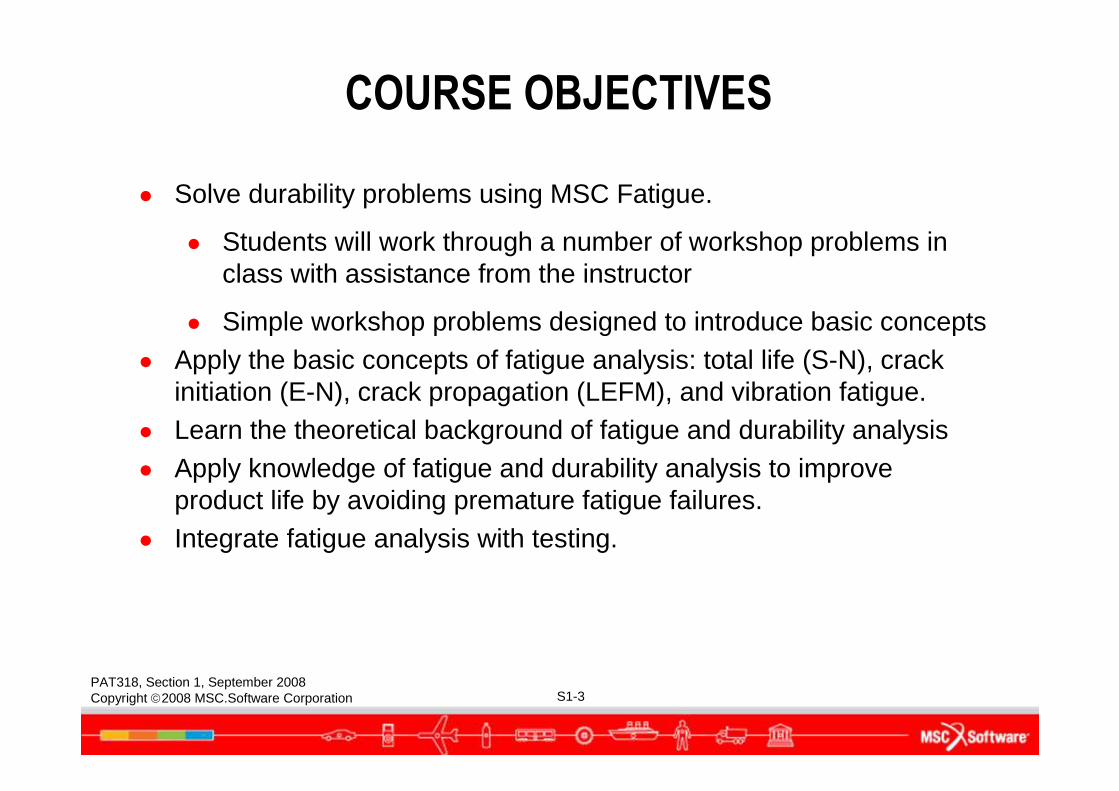
COURSE OBJECTIVES
● Solve durability problems using MSC Fatigue.
● Students will work through a number of workshop problems in class with assistance from the instructor
● Simple workshop problems designed to introduce basic concepts● Apply the basic concepts of fatigue analysis: total life (S-N), crack
initiation (E-N), crack propagation (LEFM), and vibration fatigue.● Learn the theoretical background of fatigue and durability analysis● Apply knowledge of fatigue and durability analysis to improve
product life by avoiding premature fatigue failures.● Integrate fatigue analysis with testing.
PAT318, Section 1, September 2008Copyright 2008 MSC.Software Corporation S1-4
COMPANY OVERVIEW
● The MSC Software Corporation has been supplying sophisticated computer-aided engineering (CAE) tools since 1963
● MSC Software is the developer, distributor, and supporter of the most complete and widely-used structural analysis program in the world, MD Nastran
● MSC Software is also the developer, distributor, and supporter of the state of the art CAE analysis program, Patran
● Patran is an open architecture pre- and post-processor for all major finite element analysis (FEA) software, including MD Nastran, Marc, Dytran, and others…
PAT318, Section 1, September 2008Copyright 2008 MSC.Software Corporation S1-5
MSC U.S. TECHNICAL SUPPORT
● With corporate headquarters in Santa Ana, California, MSC Software maintains regional sales and support offices throughout the US:
● The MSC Software technical support hotline (1-800-732-7284) is staffed Monday through Friday 7:00 a.m. to 3:00 p.m. PST
● Fax number is (714) 784-4056
PAT318, Section 1, September 2008Copyright 2008 MSC.Software Corporation S1-6
MSC WORLDWIDE TECHNICAL SUPPORT
● MSC.Software also maintains offices worldwide
● If appropriate, your course instructor will provide information for accessing and contacting MSC support in your area
● Sign up to the MSC Forums and become a member of our talented community at:
http://forums.mscsoftware.com/
● Methods for contacting the MSC global support team:
● Email support for Patran is via: [email protected]
● Email support for Fatigue is via: [email protected]
● Website support at: http://www.mscsoftware.com/support
● This information is also available in the Nastran and Patran release guides
PAT318, Section 1, September 2008Copyright 2008 MSC.Software Corporation S1-7
OVERVIEW OF DURABILITY AND FATIGUE LIFE ANALYSIS
PAT318, Section 1, September 2008Copyright 2008 MSC.Software Corporation S1-8
WHAT IS DURABILITY?
● Durability is…
“the ability to do what its supposed to for as long as its supposed to do it!”
● Reliability is…
“having half a chance of doing what its supposed to for as long as its supposed to do it!”
PAT318, Section 1, September 2008Copyright 2008 MSC.Software Corporation S1-9
● From a practical point of view, fatigue is:● a process where repeated variations in loading cause failure
even when the nominal stresses are below the material yield strength; and is
● made up of crack initiation and subsequent crack growth as a result of cyclic, plastic deformation.
DEFINITION OF FATIGUE
According to BS 7608:
“fatigue is the damage of a structural part by the initiation and gradual propagation of a crack or cracks caused by
repeated applications of stress”
PAT318, Section 1, September 2008Copyright 2008 MSC.Software Corporation S1-10
THE PHYSICAL BASIS OF FATIGUE
● Fatigue failures typically start at the surface of a specimen or component
● Fatigue failures start at small microscopic cracks and accordingly are very sensitive to even minute stress raisers
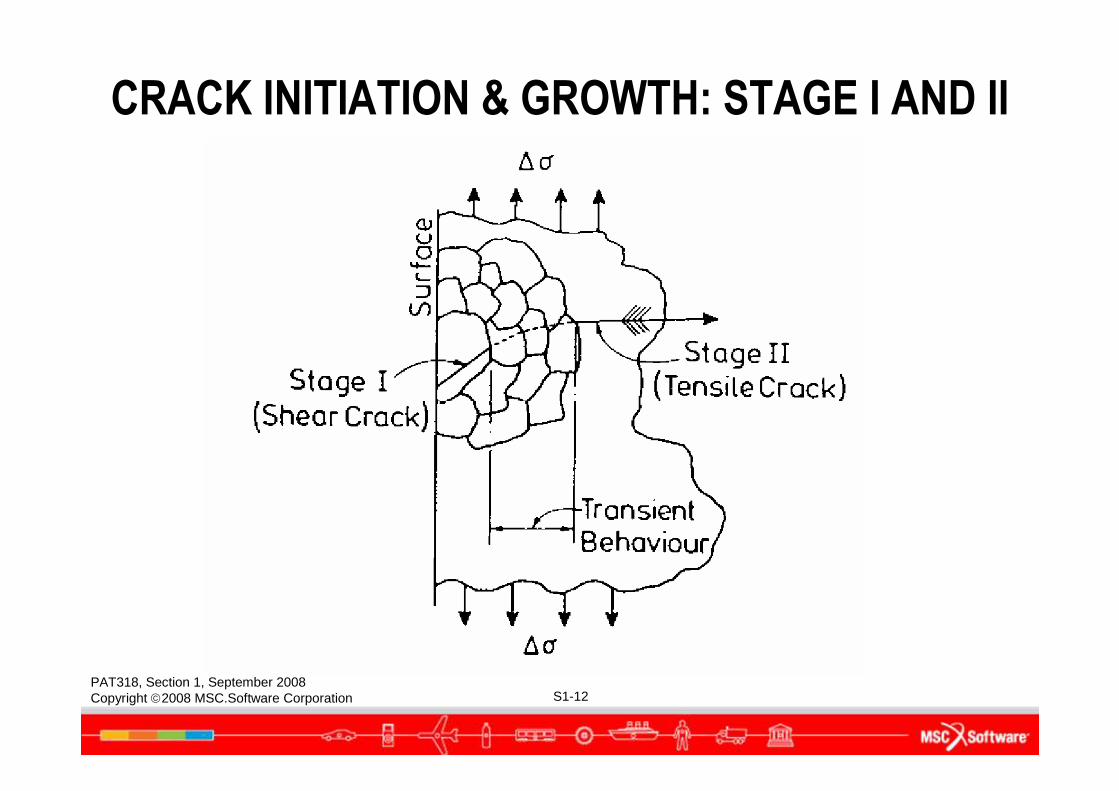
● The process of fatigue encompasses the entire range from the formation of a microcrack in a persistent slip band to the propagation of a long crack in an elastic-plastic continuum.
PAT318, Section 1, September 2008Copyright 2008 MSC.Software Corporation S1-11
There are many ways of starting a small crack:
● cracking or debonding of second phase particles; ● natural scratches and machining marks on the surface;● corrosion pits or intergranular attack;● porosity from casting;● laps from forging and forming;● brittle surface layers
THE PHYSICAL BASIS OF FATIGUE (CONT.)
PAT318, Section 1, September 2008Copyright 2008 MSC.Software Corporation S1-12
CRACK INITIATION & GROWTH: STAGE I AND II
PAT318, Section 1, September 2008Copyright 2008 MSC.Software Corporation S1-13
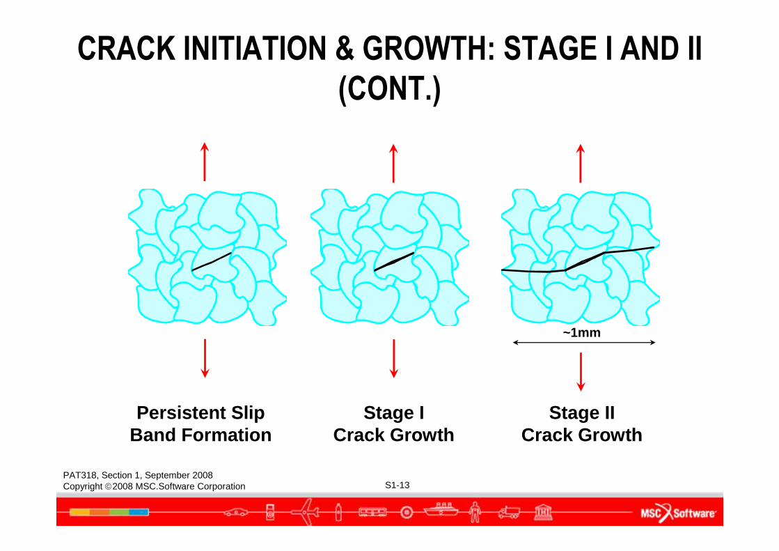
Persistent SlipBand Formation
Stage ICrack Growth
Stage IICrack Growth
~1mm
CRACK INITIATION & GROWTH: STAGE I AND II
(CONT.)
PAT318, Section 1, September 2008Copyright 2008 MSC.Software Corporation S1-14
A SHORT HISTORY OF FATIGUE
PAT318, Section 1, September 2008Copyright 2008 MSC.Software Corporation S1-15
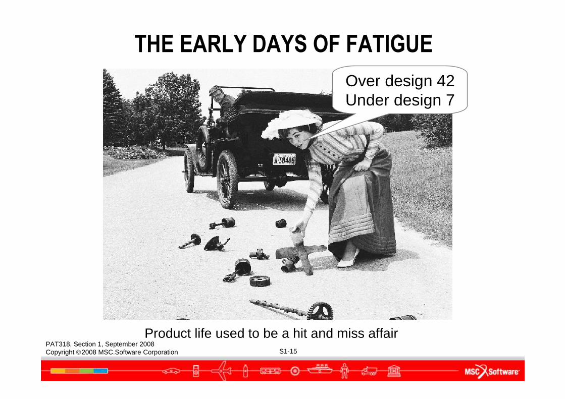
Product life used to be a hit and miss affair
Over design 42Under design 7
THE EARLY DAYS OF FATIGUE
PAT318, Section 1, September 2008Copyright 2008 MSC.Software Corporation S1-16
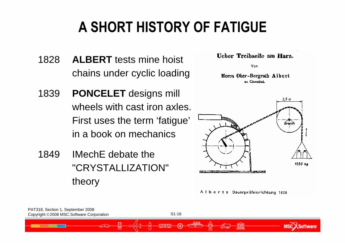
A SHORT HISTORY OF FATIGUE
1828 ALBERT tests mine hoist chains under cyclic loading
1839 PONCELET designs mill wheels with cast iron axles. First uses the term ‘fatigue’in a book on mechanics
1849 IMechE debate the "CRYSTALLIZATION" theory
PAT318, Section 1, September 2008Copyright 2008 MSC.Software Corporation S1-17
A SHORT HISTORY OF FATIGUE (CONT.)
1850+ WÖHLER conducts first systematic fatigue investigations on axles:● Develops the ROTATING-BENDING fatigue test● Concept of FATIGUE LIMIT● Development of fatigue design strategies● Identifies importance of cyclic & mean stresses● Recognizes the effect of notches ● S-N Curves appear some thirty years later
PAT318, Section 1, September 2008Copyright 2008 MSC.Software Corporation S1-18
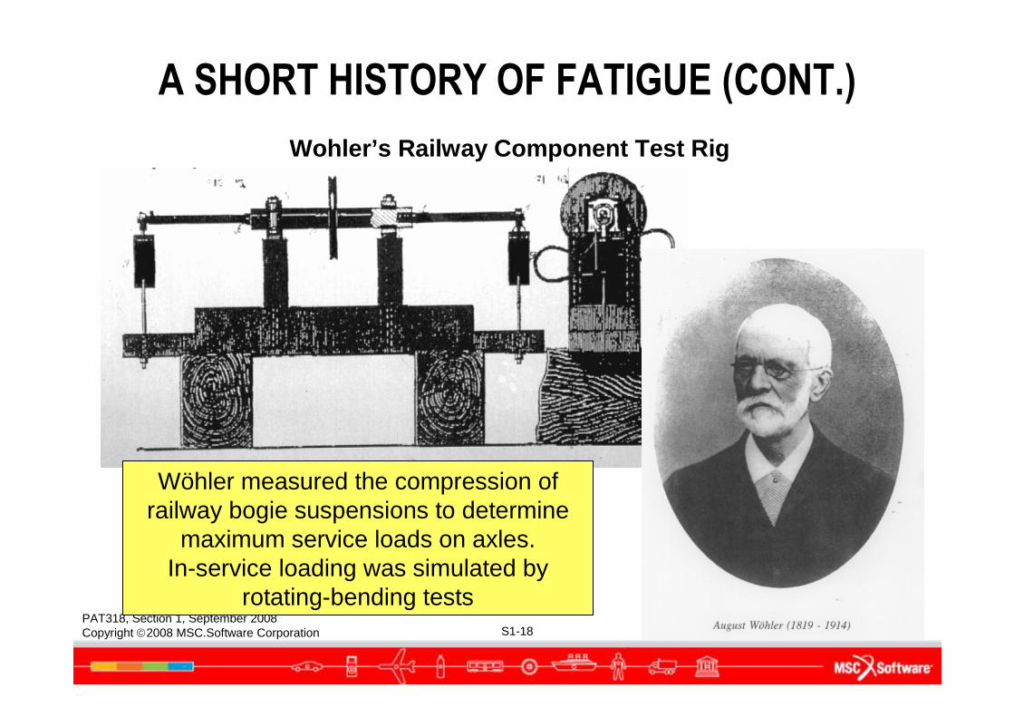
Wohler’s Railway Component Test Rig
A SHORT HISTORY OF FATIGUE (CONT.)
Wöhler measured the compression of railway bogie suspensions to determine
maximum service loads on axles. In-service loading was simulated by
rotating-bending tests
PAT318, Section 1, September 2008Copyright 2008 MSC.Software Corporation S1-19
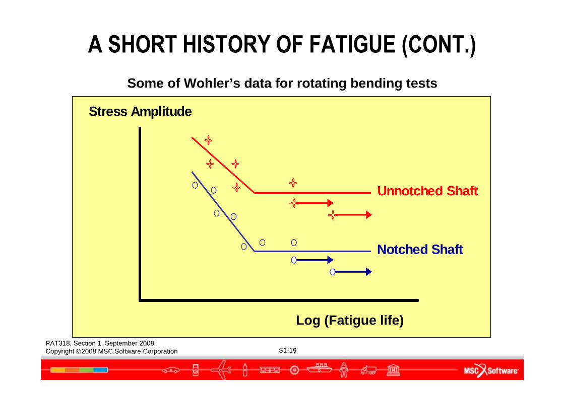
Stress Amplitude
Notched Shaft
Unnotched Shaft
Log (Fatigue life)
Some of Wohler’s data for rotating bending tests
A SHORT HISTORY OF FATIGUE (CONT.)
PAT318, Section 1, September 2008Copyright 2008 MSC.Software Corporation S1-20
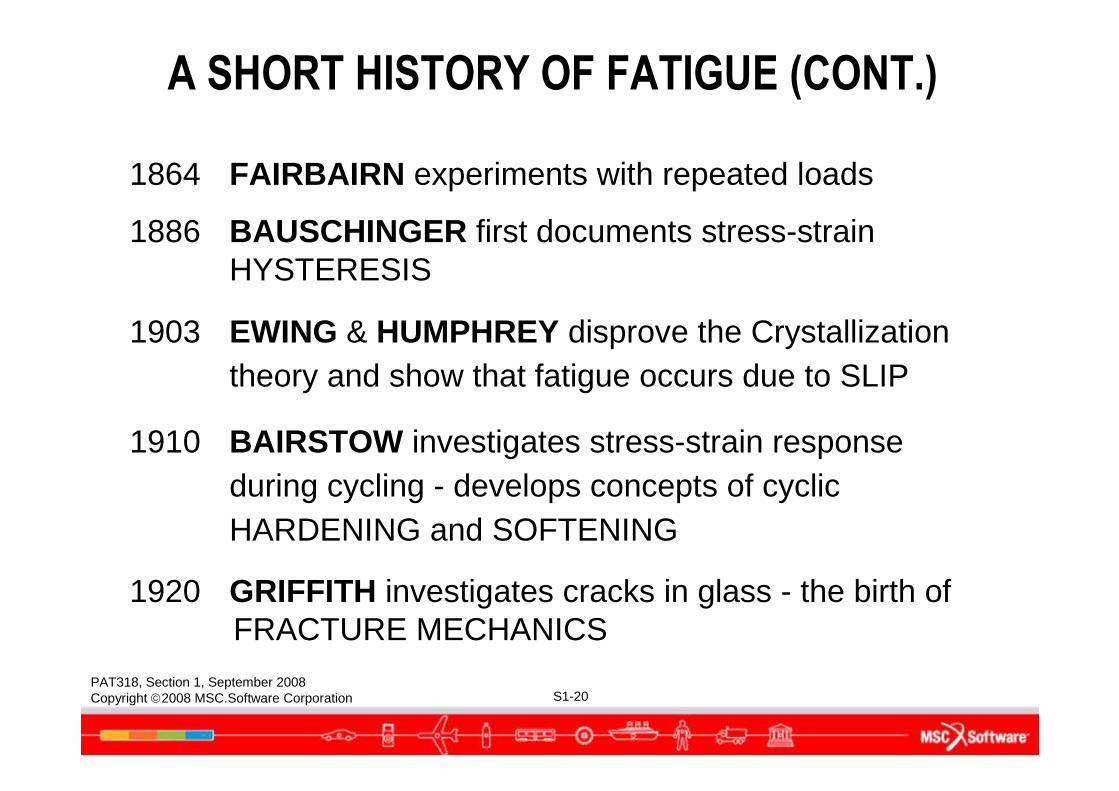
1864 FAIRBAIRN experiments with repeated loads
1886 BAUSCHINGER first documents stress-strain HYSTERESIS
1903 EWING & HUMPHREY disprove the Crystallization theory and show that fatigue occurs due to SLIP
1910 BAIRSTOW investigates stress-strain response during cycling - develops concepts of cyclic HARDENING and SOFTENING
1920 GRIFFITH investigates cracks in glass - the birth of FRACTURE MECHANICS
A SHORT HISTORY OF FATIGUE (CONT.)
PAT318, Section 1, September 2008Copyright 2008 MSC.Software Corporation S1-21
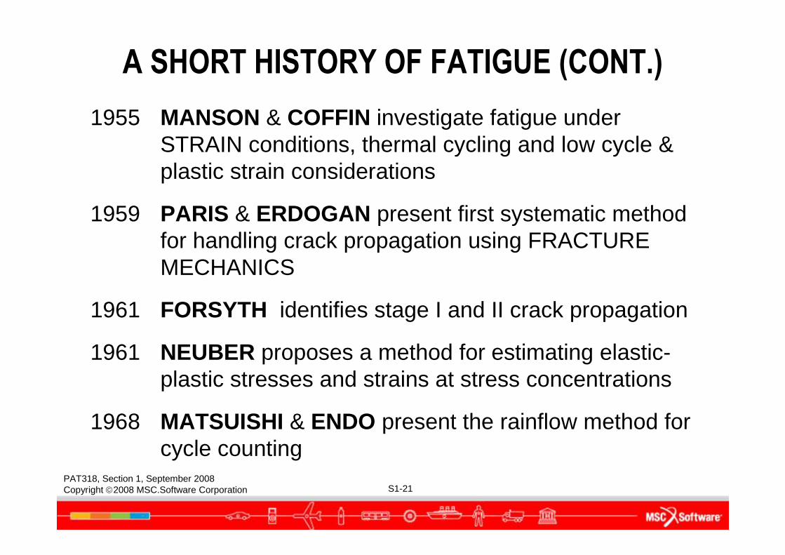
1955 MANSON & COFFIN investigate fatigue under STRAIN conditions, thermal cycling and low cycle & plastic strain considerations
1959 PARIS & ERDOGAN present first systematic method for handling crack propagation using FRACTURE MECHANICS
1961 FORSYTH identifies stage I and II crack propagation
1961 NEUBER proposes a method for estimating elastic-plastic stresses and strains at stress concentrations
1968 MATSUISHI & ENDO present the rainflow method for cycle counting
A SHORT HISTORY OF FATIGUE (CONT.)
PAT318, Section 1, September 2008Copyright 2008 MSC.Software Corporation S1-22
A SHORT HISTORY OF FATIGUE (CONT.)
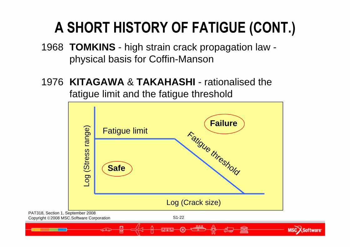
1968 TOMKINS - high strain crack propagation law -physical basis for Coffin-Manson
1976 KITAGAWA & TAKAHASHI - rationalised the fatigue limit and the fatigue threshold
Log
(Str
ess
rang
e)
Log (Crack size)
Fatigue limit Fatigue thresholdSafe
Failure
PAT318, Section 1, September 2008Copyright 2008 MSC.Software Corporation S1-23
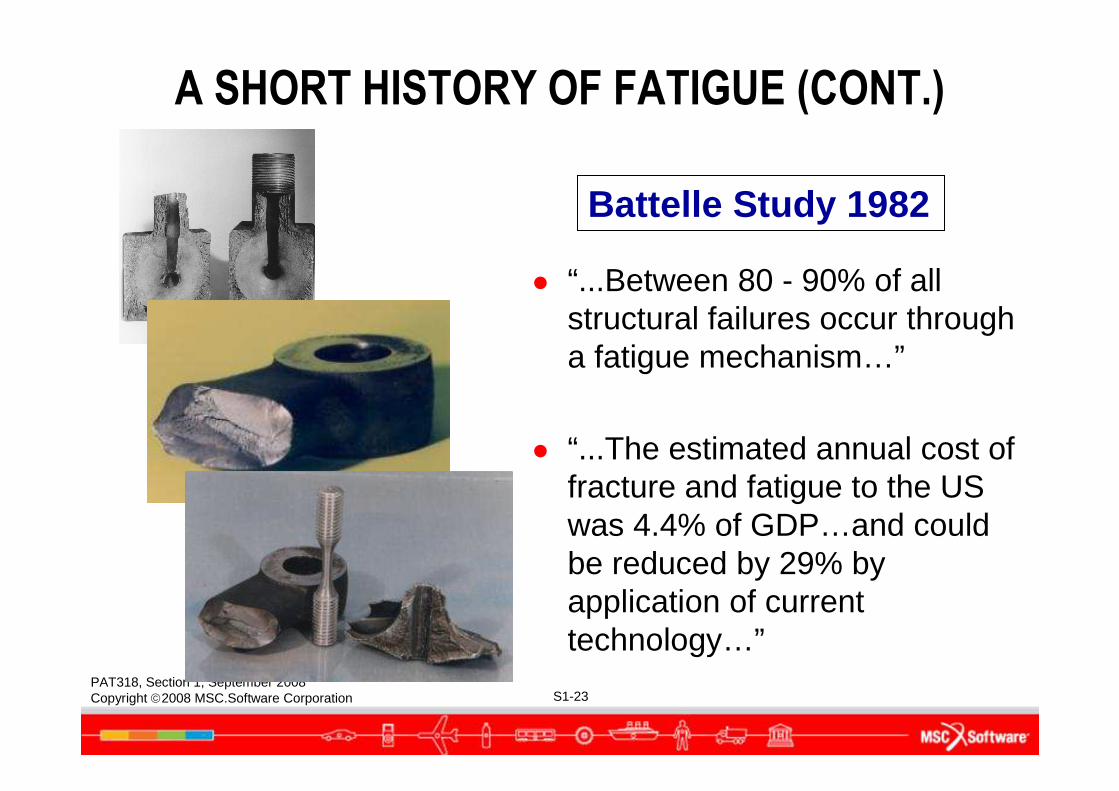
● “...Between 80 - 90% of all structural failures occur through a fatigue mechanism…”
● “...The estimated annual cost of fracture and fatigue to the US was 4.4% of GDP…and could be reduced by 29% by application of current technology…”
Battelle Study 1982
A SHORT HISTORY OF FATIGUE (CONT.)
PAT318, Section 1, September 2008Copyright 2008 MSC.Software Corporation S1-24
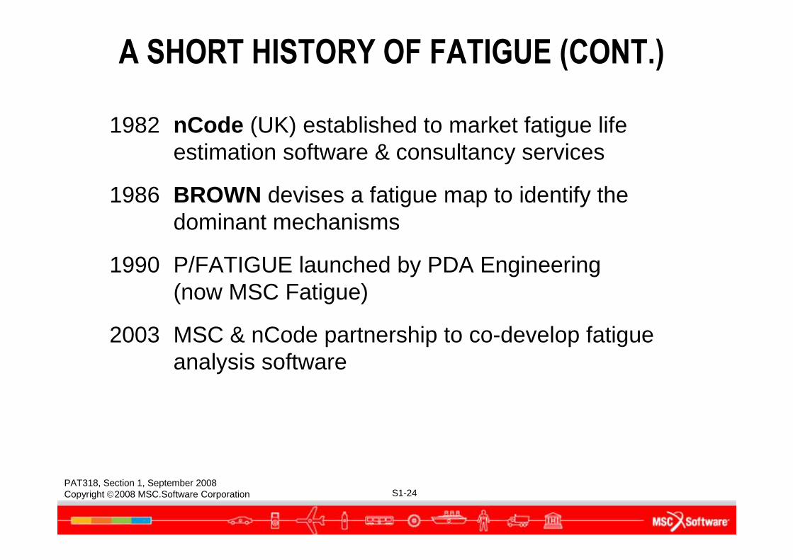
A SHORT HISTORY OF FATIGUE (CONT.)
1982 nCode (UK) established to market fatigue life estimation software & consultancy services
1986 BROWN devises a fatigue map to identify the dominant mechanisms
1990 P/FATIGUE launched by PDA Engineering(now MSC Fatigue)
2003 MSC & nCode partnership to co-develop fatigue analysis software
PAT318, Section 1, September 2008Copyright 2008 MSC.Software Corporation S1-25
Prof. D. SocieUniversity of IIIinois,1990
FATIGUE FAILURE & EDUCATION
"Despite 150 years of fatigue research, unintended fatigue failures still occur.
More research will NOT reduce the incidence of fatigue failure - more education will!"
PAT318, Section 1, September 2008Copyright 2008 MSC.Software Corporation S1-26
USE OF FATIGUE TECHNOLOGY
PAT318, Section 1, September 2008Copyright 2008 MSC.Software Corporation S1-27
USE OF FATIGUE TECHNOLOGY
● Fatigue analysis is not new (60-170 years old);
● A collection of empirical rules to fit observed behaviour;
● Does not require the engineer exploiting it to understand all the finer points;
● Can be used (with training and experience) to achieve Integrated Durability Management (IDM) goals.
PAT318, Section 1, September 2008Copyright 2008 MSC.Software Corporation S1-28
FATIGUE CALCULATIONS IN…
● Concept design phase:Analytical loads, previous design loads, estimated properties, early design optimization
● Verification phase:Measured loads, real properties, design refinement and optimization
● Production phase:Continued development, new markets, firefighting
PAT318, Section 1, September 2008Copyright 2008 MSC.Software Corporation S1-29
WHO USES FATIGUE ANALYSIS?
● Design engineer:Design optimization for durability on the “virtual component”
● Development engineerMeasures data on the “real component”, tells the design analyst where it’s wrong and how to fix it.
● Test rig engineerPre-predicts rig tests and edits out non damaging cycles to speed them up.
● Production engineerInvestigates service failures, monitors production, feeds back improvement ideas.
PAT318, Section 1, September 2008Copyright 2008 MSC.Software Corporation S1-30
DESIGNING AGAINST FATIGUE FAILURE
Requirements:
● Higher Performance
● Lower Weight
● Longer Life
● Reasonable Cost
● As Soon As Possible
PAT318, Section 1, September 2008Copyright 2008 MSC.Software Corporation S1-31
DESIGNING AGAINST FATIGUE FAILURE (CONT.)
Constraints:● Life calculations are much less precise than strength calculations● Fatigue properties can not be inferred from static mechanical
properties● Laboratory tests often exhibit scatter and are difficult to translate to
full size components● Full scale prototype testing is often required to confirm an
acceptable life● Designs should be ‘defect tolerant’ - stressing and materials
selection to ensure slow crack growth and detectability before failure
● Designs should be ‘Fail Safe’, where possible
PAT318, Section 1, September 2008Copyright 2008 MSC.Software Corporation S1-32
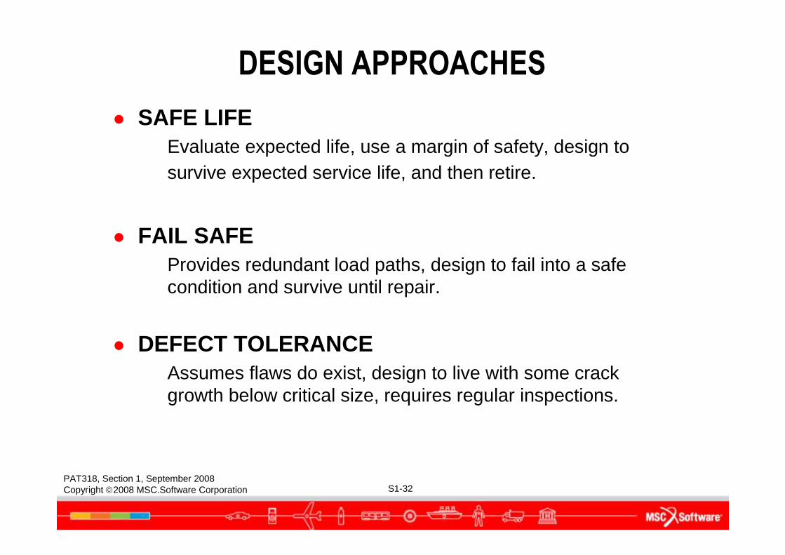
DESIGN APPROACHES
● SAFE LIFEEvaluate expected life, use a margin of safety, design to survive expected service life, and then retire.
● FAIL SAFEProvides redundant load paths, design to fail into a safe condition and survive until repair.
● DEFECT TOLERANCEAssumes flaws do exist, design to live with some crack growth below critical size, requires regular inspections.
PAT318, Section 1, September 2008Copyright 2008 MSC.Software Corporation S1-33
WHAT DRIVES DURABILITY MANAGEMENT?
PAT318, Section 1, September 2008Copyright 2008 MSC.Software Corporation S1-34
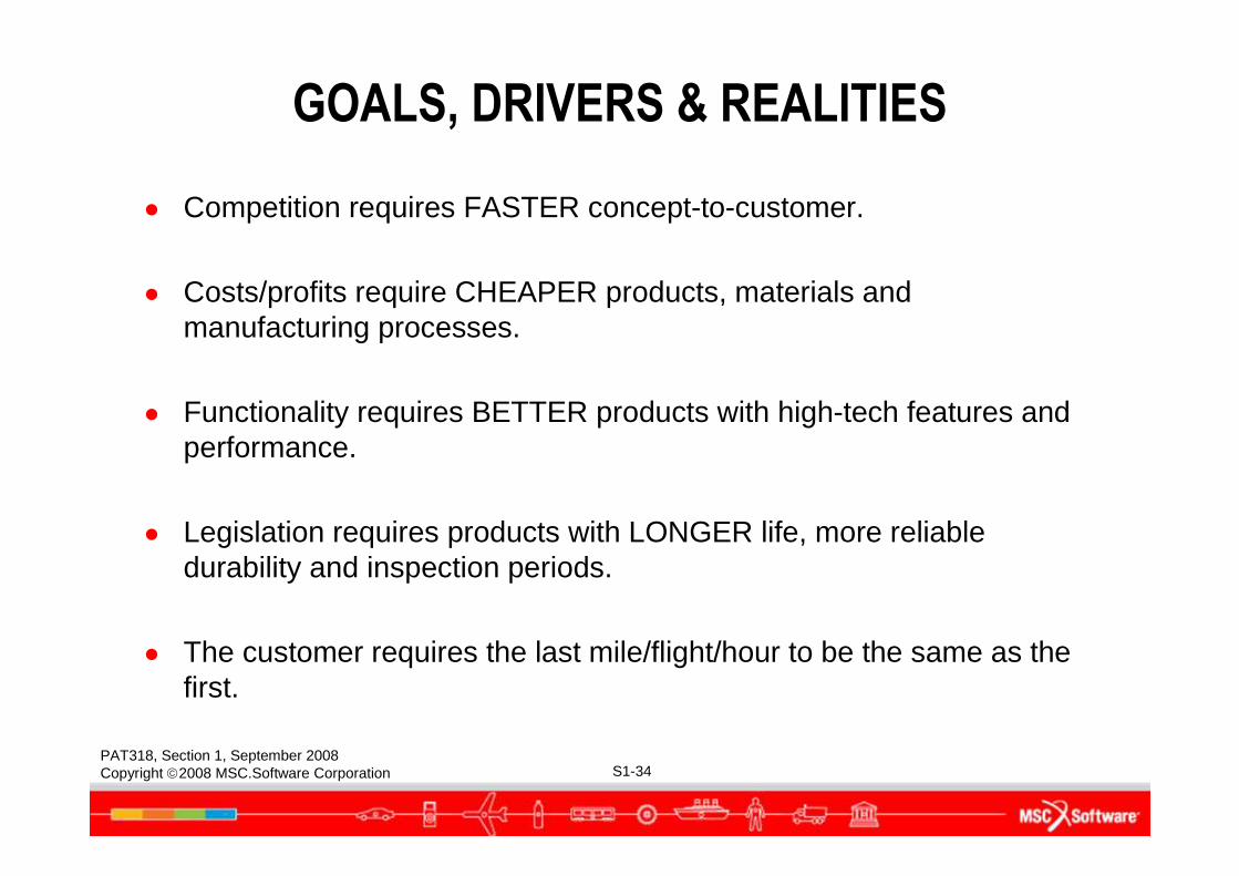
GOALS, DRIVERS & REALITIES
● Competition requires FASTER concept-to-customer.
● Costs/profits require CHEAPER products, materials and manufacturing processes.
● Functionality requires BETTER products with high-tech features and performance.
● Legislation requires products with LONGER life, more reliable durability and inspection periods.
● The customer requires the last mile/flight/hour to be the same as the first.
PAT318, Section 1, September 2008Copyright 2008 MSC.Software Corporation S1-35
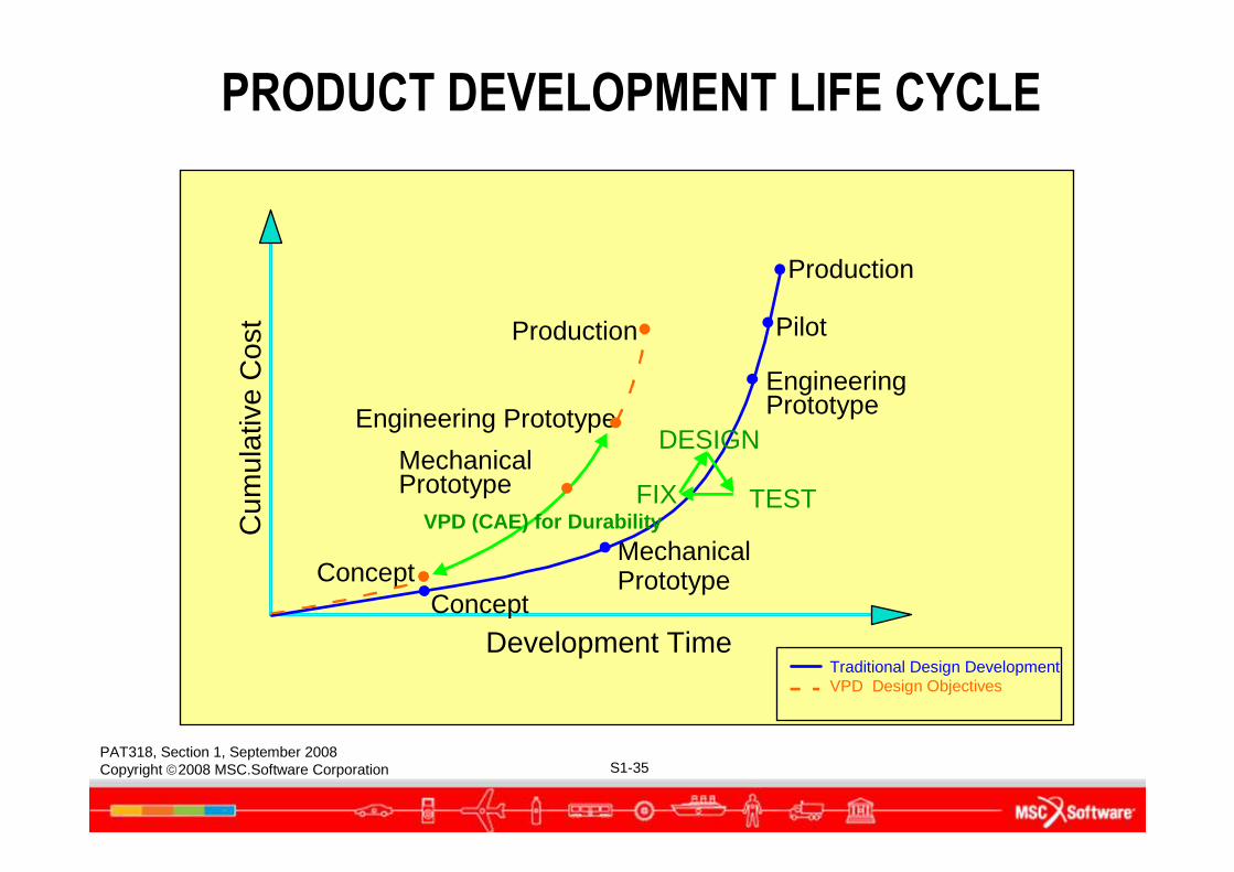
Production
Production
Pilot
Engineering PrototypeEngineeringPrototype
Traditional Design DevelopmentVPD Design Objectives
FIX TEST
Mechanical Prototype
MechanicalPrototypeConcept
Concept
Development Time
Cum
ulat
ive
Cos
t
DESIGN
VPD (CAE) for Durability
PRODUCT DEVELOPMENT LIFE CYCLE
PAT318, Section 1, September 2008Copyright 2008 MSC.Software Corporation S1-36
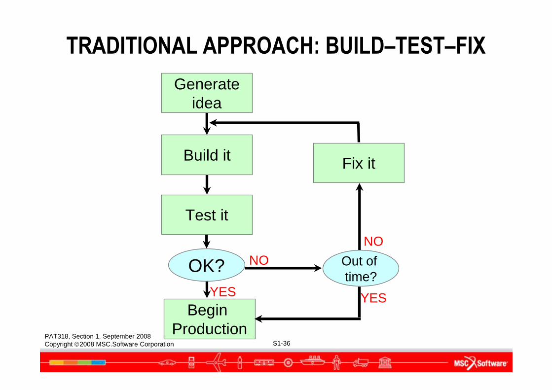
TRADITIONAL APPROACH: BUILD–TEST–FIX
Build it
Test it
Begin Production
Out of time?
NONO
YES
Generateidea
Fix it
OK?YES
PAT318, Section 1, September 2008Copyright 2008 MSC.Software Corporation S1-37
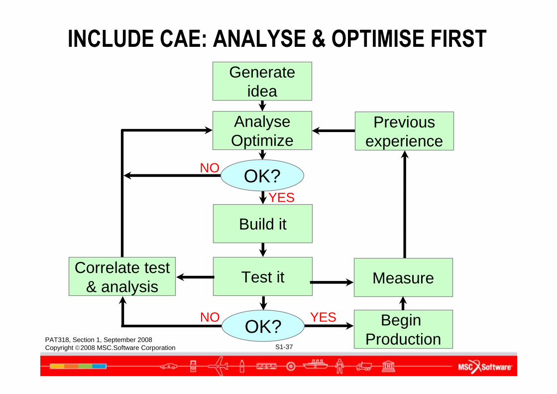
INCLUDE CAE: ANALYSE & OPTIMISE FIRST
Generateidea
AnalyseOptimize
Build it
Test it
OK?
OK? Begin Production
Measure
NO YES
NO
YES
Previousexperience
Correlate test& analysis
PAT318, Section 1, September 2008Copyright 2008 MSC.Software Corporation S1-38
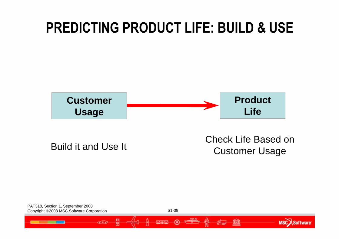
CustomerUsage
ProductLife
Build it and Use ItCheck Life Based on
Customer Usage
PREDICTING PRODUCT LIFE: BUILD & USE
PAT318, Section 1, September 2008Copyright 2008 MSC.Software Corporation S1-39
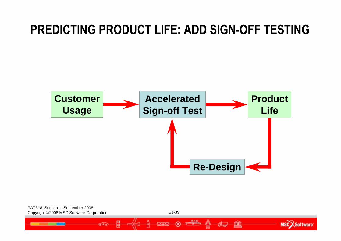
CustomerUsage
AcceleratedSign-off Test
ProductLife
Re-Design
PREDICTING PRODUCT LIFE: ADD SIGN-OFF TESTING
PAT318, Section 1, September 2008Copyright 2008 MSC.Software Corporation S1-40
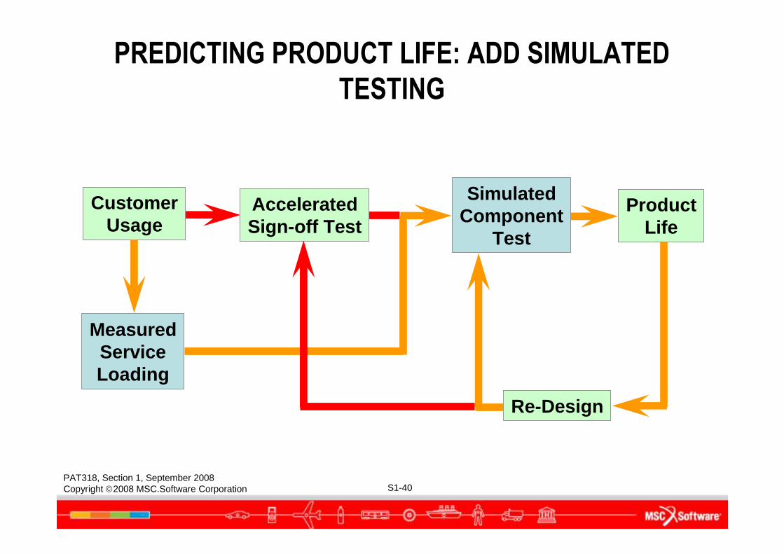
CustomerUsage
AcceleratedSign-off Test
ProductLife
SimulatedComponent
Test
MeasuredServiceLoading
PREDICTING PRODUCT LIFE: ADD SIMULATED
TESTING
Re-Design
PAT318, Section 1, September 2008Copyright 2008 MSC.Software Corporation S1-41
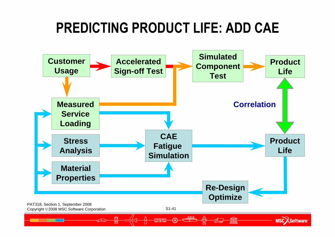
PREDICTING PRODUCT LIFE: ADD CAE
SimulatedComponent
Test
CAEFatigue
Simulation
CustomerUsage
MeasuredServiceLoading
StressAnalysis
MaterialProperties
Product Life
Correlation
AcceleratedSign-off Test
Re-DesignOptimize
Product Life
PAT318, Section 1, September 2008Copyright 2008 MSC.Software Corporation S1-42
OVERVIEW OF FATIGUE LIFE CALCULATION METHODS
PAT318, Section 1, September 2008Copyright 2008 MSC.Software Corporation S1-43
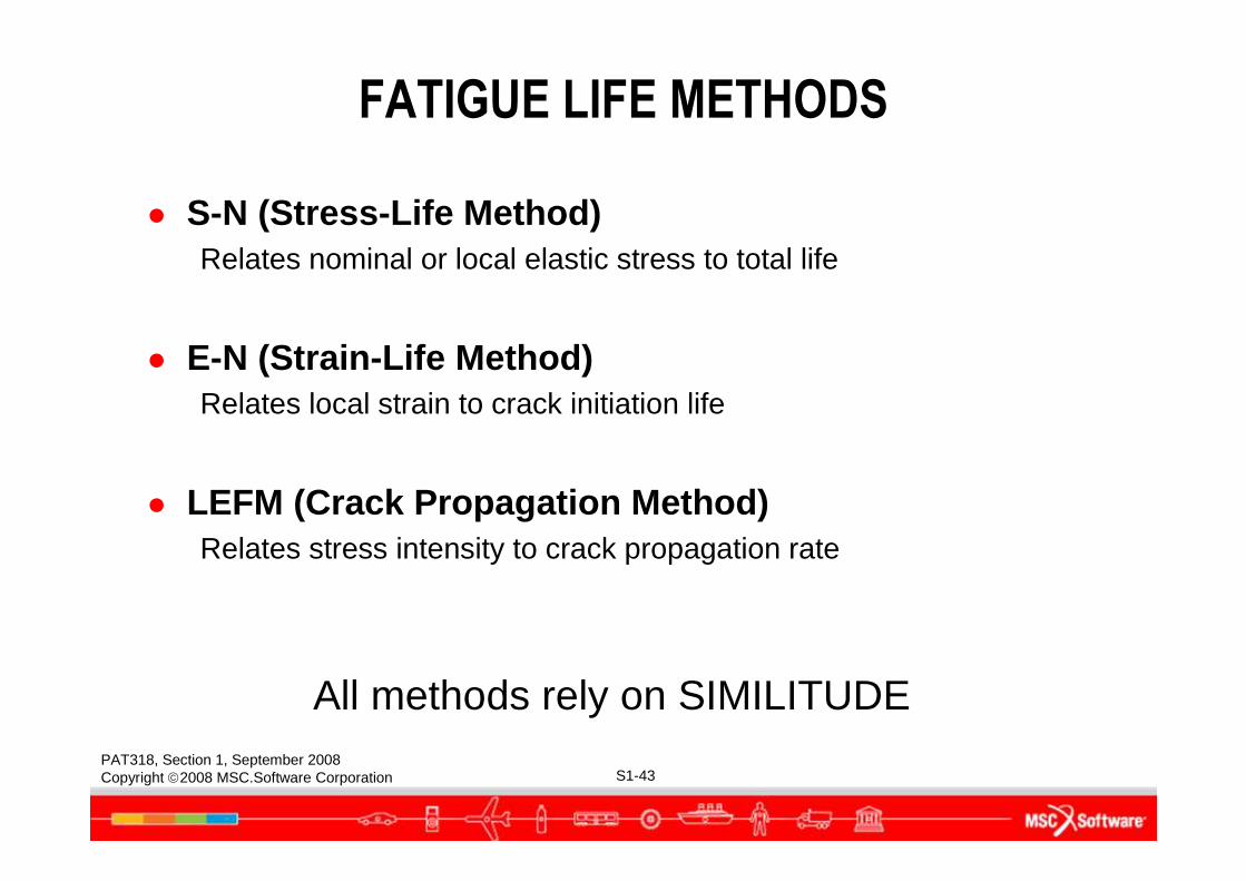
FATIGUE LIFE METHODS
● S-N (Stress-Life Method)Relates nominal or local elastic stress to total life
● E-N (Strain-Life Method)Relates local strain to crack initiation life
● LEFM (Crack Propagation Method)Relates stress intensity to crack propagation rate
All methods rely on SIMILITUDE
PAT318, Section 1, September 2008Copyright 2008 MSC.Software Corporation S1-44
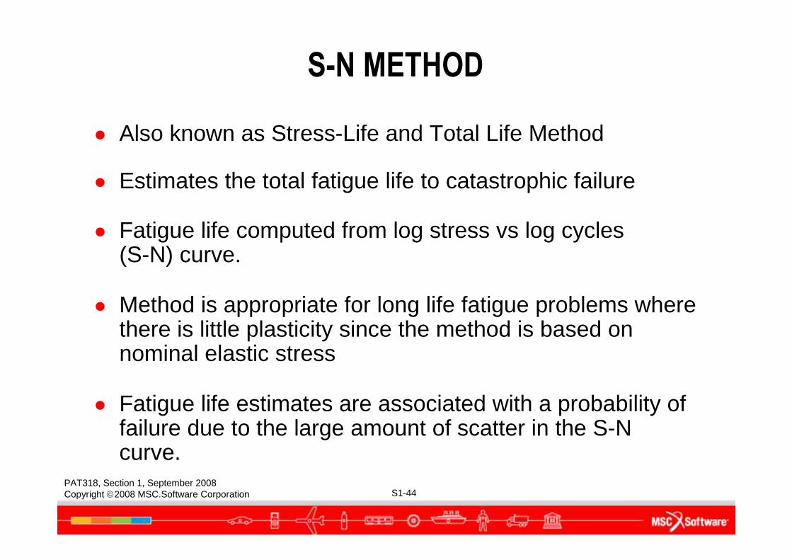
● Also known as Stress-Life and Total Life Method
● Estimates the total fatigue life to catastrophic failure
● Fatigue life computed from log stress vs log cycles (S-N) curve.
● Method is appropriate for long life fatigue problems where there is little plasticity since the method is based on nominal elastic stress
● Fatigue life estimates are associated with a probability of failure due to the large amount of scatter in the S-N curve.
S-N METHOD
PAT318, Section 1, September 2008Copyright 2008 MSC.Software Corporation S1-45
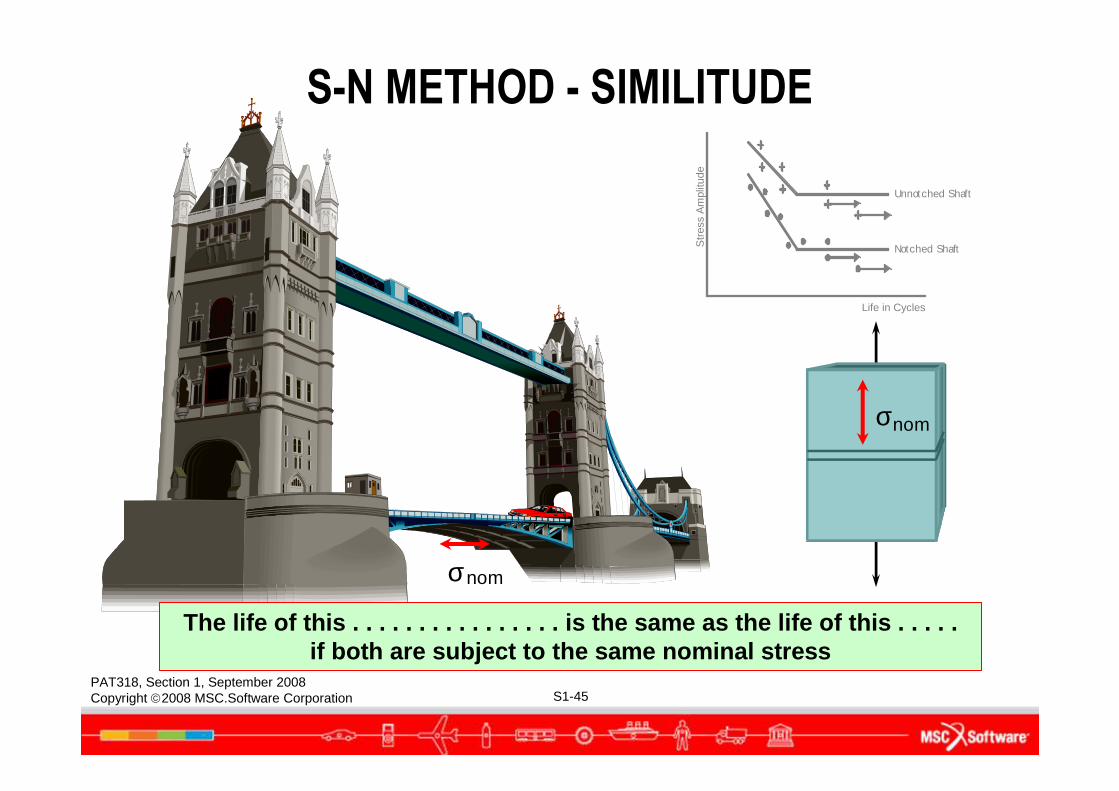
σnom
nomσ
Notched Shaft
Unnotched Shaft
Str
ess
Am
plitu
de
Life in Cycles
S-N METHOD - SIMILITUDE
The life of this . . . . . . . . . . . . . . . . is the same as the life of this . . . . .if both are subject to the same nominal stress
PAT318, Section 1, September 2008Copyright 2008 MSC.Software Corporation S1-46
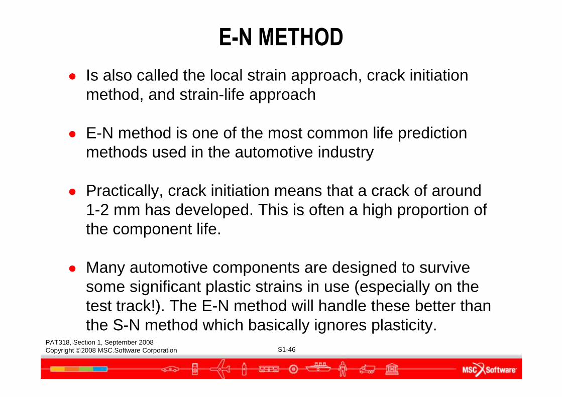
● Is also called the local strain approach, crack initiation method, and strain-life approach
● E-N method is one of the most common life prediction methods used in the automotive industry
● Practically, crack initiation means that a crack of around 1-2 mm has developed. This is often a high proportion of the component life.
● Many automotive components are designed to survive some significant plastic strains in use (especially on the test track!). The E-N method will handle these better than the S-N method which basically ignores plasticity.
E-N METHOD
PAT318, Section 1, September 2008Copyright 2008 MSC.Software Corporation S1-47
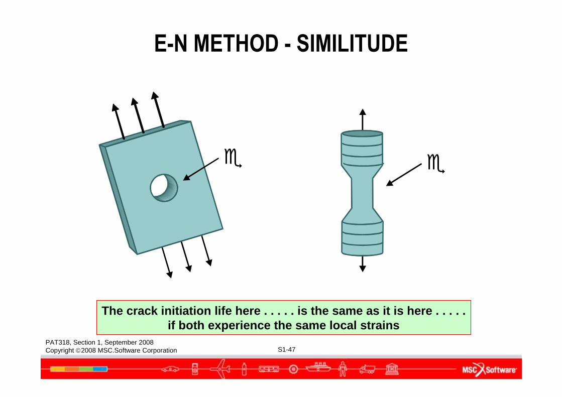
The crack initiation life here . . . . . is the same as it is here . . . . .if both experience the same local strains
� �
E-N METHOD - SIMILITUDE
PAT318, Section 1, September 2008Copyright 2008 MSC.Software Corporation S1-48
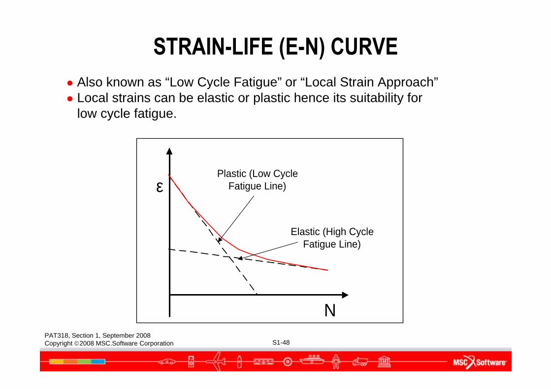
● Also known as “Low Cycle Fatigue” or “Local Strain Approach”● Local strains can be elastic or plastic hence its suitability for
low cycle fatigue.
ε
N
Plastic (Low CycleFatigue Line)
Elastic (High CycleFatigue Line)
STRAIN-LIFE (E-N) CURVE
PAT318, Section 1, September 2008Copyright 2008 MSC.Software Corporation S1-49
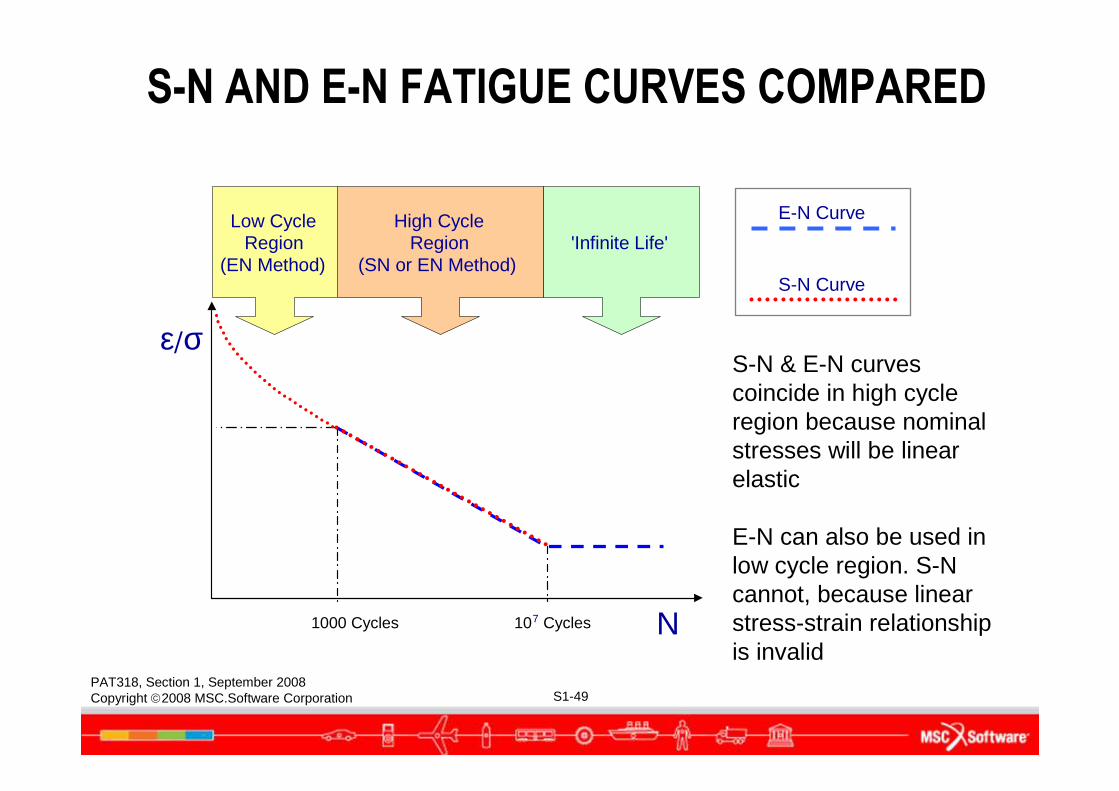
ε/σ
N1000 Cycles
Low CycleRegion
(EN Method)
High CycleRegion
(SN or EN Method)'Infinite Life'
107 Cycles
E-N Curve
S-N Curve
S-N & E-N curves coincide in high cycle region because nominal stresses will be linear elastic
E-N can also be used in low cycle region. S-N cannot, because linear stress-strain relationship is invalid
S-N AND E-N FATIGUE CURVES COMPARED
PAT318, Section 1, September 2008Copyright 2008 MSC.Software Corporation S1-50
CRACK PROPAGATION (LEFM) METHOD
● What remnant life is there after initiation?
● What is the safe life or inspection schedule for a component that is or may be cracked?
● The crack growth method is based on the principles of Linear Elastic Fracture Mechanics (LEFM)
● It relates stress intensity factors to crack growth rates
● It uses cycle-by-cycle calculations to predict lifetimes
● It is frequently used in Aerospace, Offshore, and Power Generation industries
PAT318, Section 1, September 2008Copyright 2008 MSC.Software Corporation S1-51
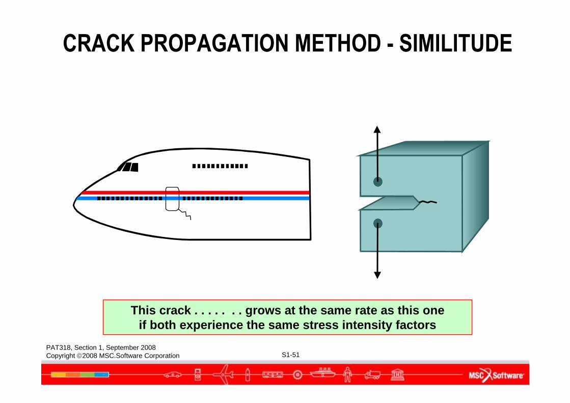
This crack . . . . . . . grows at the same rate as this oneif both experience the same stress intensity factors
CRACK PROPAGATION METHOD - SIMILITUDE
PAT318, Section 1, September 2008Copyright 2008 MSC.Software Corporation S1-52
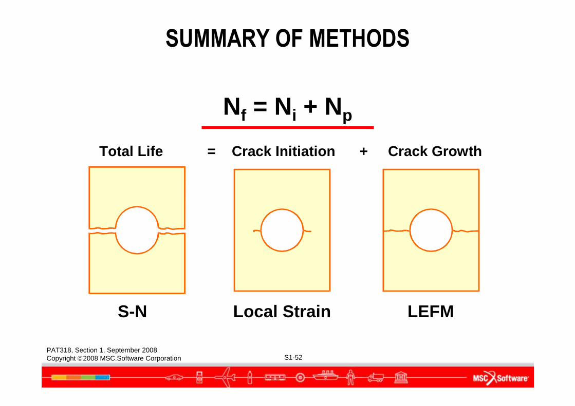
Total Life = Crack Initiation + Crack Growth
S-N Local Strain LE FM
Nf = Ni + Np
SUMMARY OF METHODS
PAT318, Section 1, September 2008Copyright 2008 MSC.Software Corporation S1-53
INTEGRATEDDURABILITY MANAGEMENT
PAT318, Section 1, September 2008Copyright 2008 MSC.Software Corporation S1-54
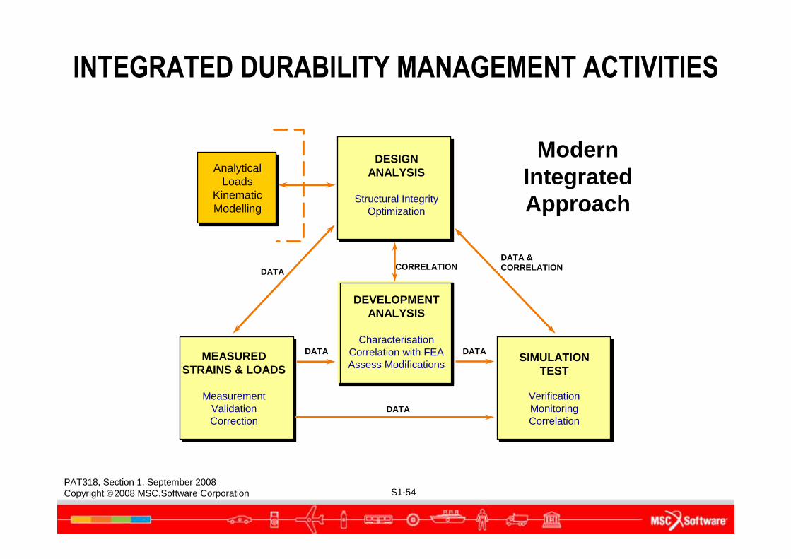
DESIGNANALYSIS
Structural IntegrityOptimization
DEVELOPMENTANALYSIS
CharacterisationCorrelation with FEAAssess Modifications
SIMULATIONTEST
VerificationMonitoringCorrelation
MEASUREDSTRAINS & LOADS
MeasurementValidationCorrection
AnalyticalLoads
KinematicModelling
DATA
DATA DATA
DATA
DATA &CORRELATIONCORRELATION
Modern Integrated Approach
INTEGRATED DURABILITY MANAGEMENT ACTIVITIES
PAT318, Section 1, September 2008Copyright 2008 MSC.Software Corporation S1-55
INTEGRATED APPROACH TO DURABILITY
Facts:● Testing is not a good way to optimize designs, but is always
required for sign-off.
● Useful fatigue analysis requires verification and good test-based information.
● Neither testing nor analysis have exclusively the “right” fatigue answer; therefore its not an argument between rivals.
● Best results are obtained when an integrated approach is adopted incorporating analysis and testing.
PAT318, Section 1, September 2008Copyright 2008 MSC.Software Corporation S1-56
HOW TESTING SUPPORTS ANALYSIS
● Provision of load data
● Provision of material fatigue properties
● Verification of stress/strain analysis results
● Correlation of life predictions
● Final sign-off
PAT318, Section 1, September 2008Copyright 2008 MSC.Software Corporation S1-57
HOW ANALYSIS SUPPORTS TESTING
● Eliminate unnecessary tests
● Test acceleration
● Gauge type selection and positioning
● Test design
PAT318, Section 1, September 2008Copyright 2008 MSC.Software Corporation S1-58
AN OVERVIEW OFVIRTUAL DURABILITY
PAT318, Section 1, September 2008Copyright 2008 MSC.Software Corporation S1-59
VIRTUAL DURABILITY ANALYSIS
● FE stress analysis is a pre-processing activity for durability analysis
● The essential requirement is for good local stress information in the critical areas
● Loading information can be: ● Assumed (idealized loading), ● Experimentally acquired ● Semi-analytical loads● Computed (full analytical loads)
PAT318, Section 1, September 2008Copyright 2008 MSC.Software Corporation S1-60
Achieving Faster, Cheaper, Better in Integrated DurabilityManagement requires:
● Integrated multi-disciplinary teams.● Integrated software tools common to all departments.● Integrated data exchange within company structure.● Integrated data exchange between the company and
its suppliers and service providers.
VIRTUAL DURABILITY ANALYSIS (CONT.)
PAT318, Section 1, September 2008Copyright 2008 MSC.Software Corporation S1-61
Prof. Rod SmithUniversity of Sheffield,1990
“Engineering is the art of being approximately right rather than exactly wrong.”

PAT318, Section 1, September 2008Copyright 2008 MSC.Software Corporation S1-62


![LECTURE 1 INTRO TO FOR1000 2011 - IFMLabifmlab.for.unb.ca/.../For1001/Lectures/Lec01.pdf · Microsoft PowerPoint - LECTURE 1 INTRO TO FOR1000 2011 [Compatibility Mode] Author: John](https://static.fdocuments.net/doc/165x107/5f0f26137e708231d442ba75/lecture-1-intro-to-for1000-2011-microsoft-powerpoint-lecture-1-intro-to-for1000.jpg)