![[ASL] Marking Scheme](https://static.fdocuments.net/doc/165x107/55cf9d7e550346d033addb8a/asl-marking-scheme.jpg)
LEAVING CERTIFICATE 2008 MARKING SCHEME CONSTRUCTION ... ol ms_1.pdf · MARKING SCHEME CONSTRUCTION...
30
Coimisiún na Scrúduithe Stáit State Examinations Commission LEAVING CERTIFICATE 2008 MARKING SCHEME CONSTRUCTION STUDIES ORDINARY LEVEL
Transcript of LEAVING CERTIFICATE 2008 MARKING SCHEME CONSTRUCTION ... ol ms_1.pdf · MARKING SCHEME CONSTRUCTION...

Coimisiún na Scrúduithe StáitState Examinations Commission
LEAVING CERTIFICATE 2008
MARKING SCHEME
CONSTRUCTION STUDIES
ORDINARY LEVEL

LEAVING CERTIFICATE 2008
MARKING SCHEME
CONSTRUCTION STUDIES
ORDINARY LEVEL
1
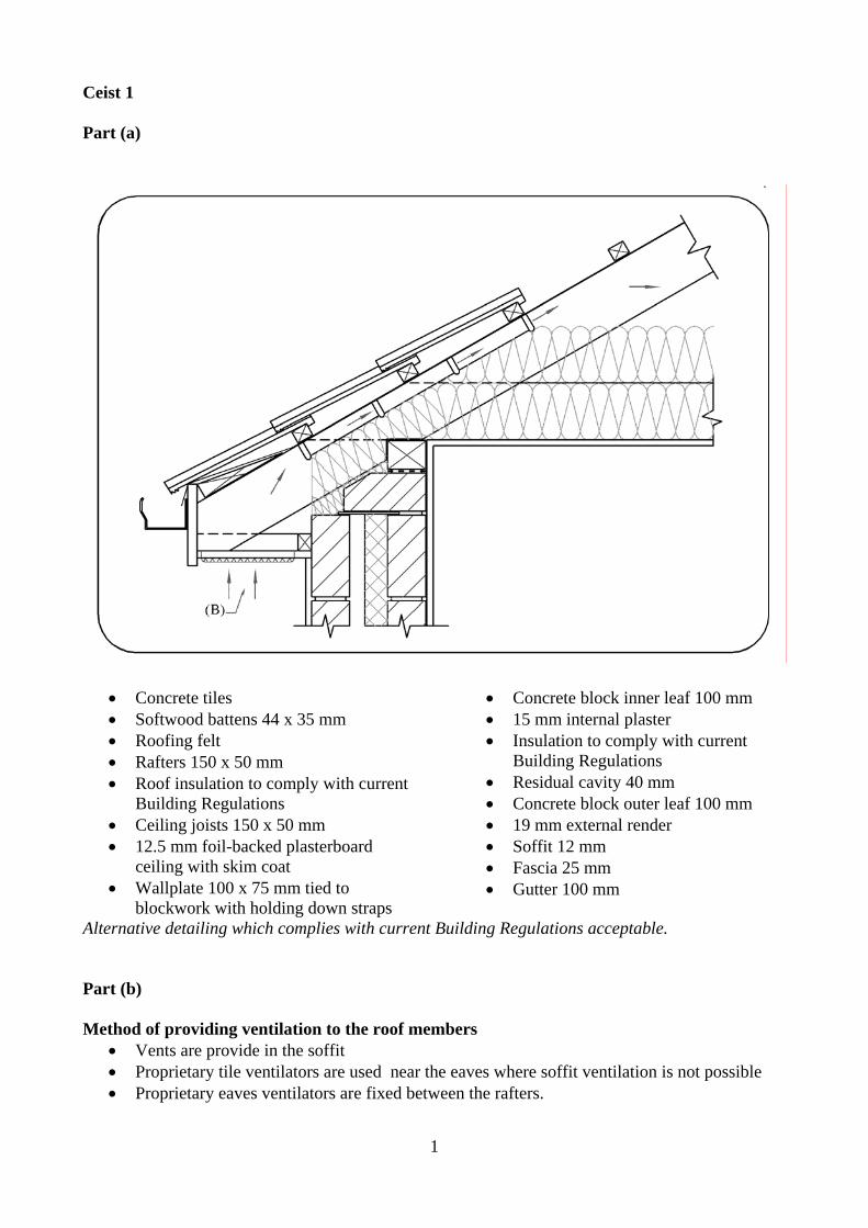
Ceist 1 Part (a)
• Concrete tiles • Softwood battens 44 x 35 mm • Roofing felt • Rafters 150 x 50 mm • Roof insulation to comply with current
Building Regulations • Ceiling joists 150 x 50 mm • 12.5 mm foil-backed plasterboard
ceiling with skim coat • Wallplate 100 x 75 mm tied to
blockwork with holding down straps
• Concrete block inner leaf 100 mm • 15 mm internal plaster • Insulation to comply with current
Building Regulations • Residual cavity 40 mm • Concrete block outer leaf 100 mm • 19 mm external render • Soffit 12 mm • Fascia 25 mm • Gutter 100 mm
Alternative detailing which complies with current Building Regulations acceptable. Part (b) Method of providing ventilation to the roof members
• Vents are provide in the soffit • Proprietary tile ventilators are used near the eaves where soffit ventilation is not possible • Proprietary eaves ventilators are fixed between the rafters.
2
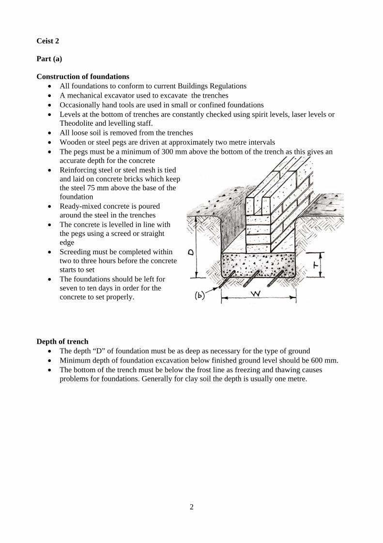
Ceist 2 Part (a) Construction of foundations
• All foundations to conform to current Buildings Regulations • A mechanical excavator used to excavate the trenches • Occasionally hand tools are used in small or confined foundations • Levels at the bottom of trenches are constantly checked using spirit levels, laser levels or
Theodolite and levelling staff. • All loose soil is removed from the trenches • Wooden or steel pegs are driven at approximately two metre intervals • The pegs must be a minimum of 300 mm above the bottom of the trench as this gives an
accurate depth for the concrete • Reinforcing steel or steel mesh is tied
and laid on concrete bricks which keep the steel 75 mm above the base of the foundation
• Ready-mixed concrete is poured around the steel in the trenches
• The concrete is levelled in line with the pegs using a screed or straight edge
• Screeding must be completed within two to three hours before the concrete starts to set
• The foundations should be left for seven to ten days in order for the concrete to set properly.
Depth of trench
• The depth “D” of foundation must be as deep as necessary for the type of ground • Minimum depth of foundation excavation below finished ground level should be 600 mm. • The bottom of the trench must be below the frost line as freezing and thawing causes
problems for foundations. Generally for clay soil the depth is usually one metre.

3
Width of foundation • The minimum width “W” of foundation must
be three times the wall thickness “W.T”. • For a 300 mm wall the minimum is 900 mm.
Thickness of foundation
• The minimum concrete thickness “T” should be not less than 300 mm
Position of a 300 mm wall on the foundation
• Walls must be built in the centre of the foundation
• The projections “P” on both sides must be equal
Part (b) Design detail
• The projection “P” should be less than the thickness “T” or at most be equal to “T” to avoid shear failure
• Reinforcing concrete with steel makes a very good composite material ideal for foundations
• The concrete takes the compressive strength and the steel takes the tensile strength
• Three steel rods diameter 12 mm generally used Sketch shows foundations without reinforcing and consequent shear
• Steel mesh may also be used • The steel is placed near the bottom of the concrete where the main tensile strength is needed • The concrete is poured and compacted around the reinforcing steel
4
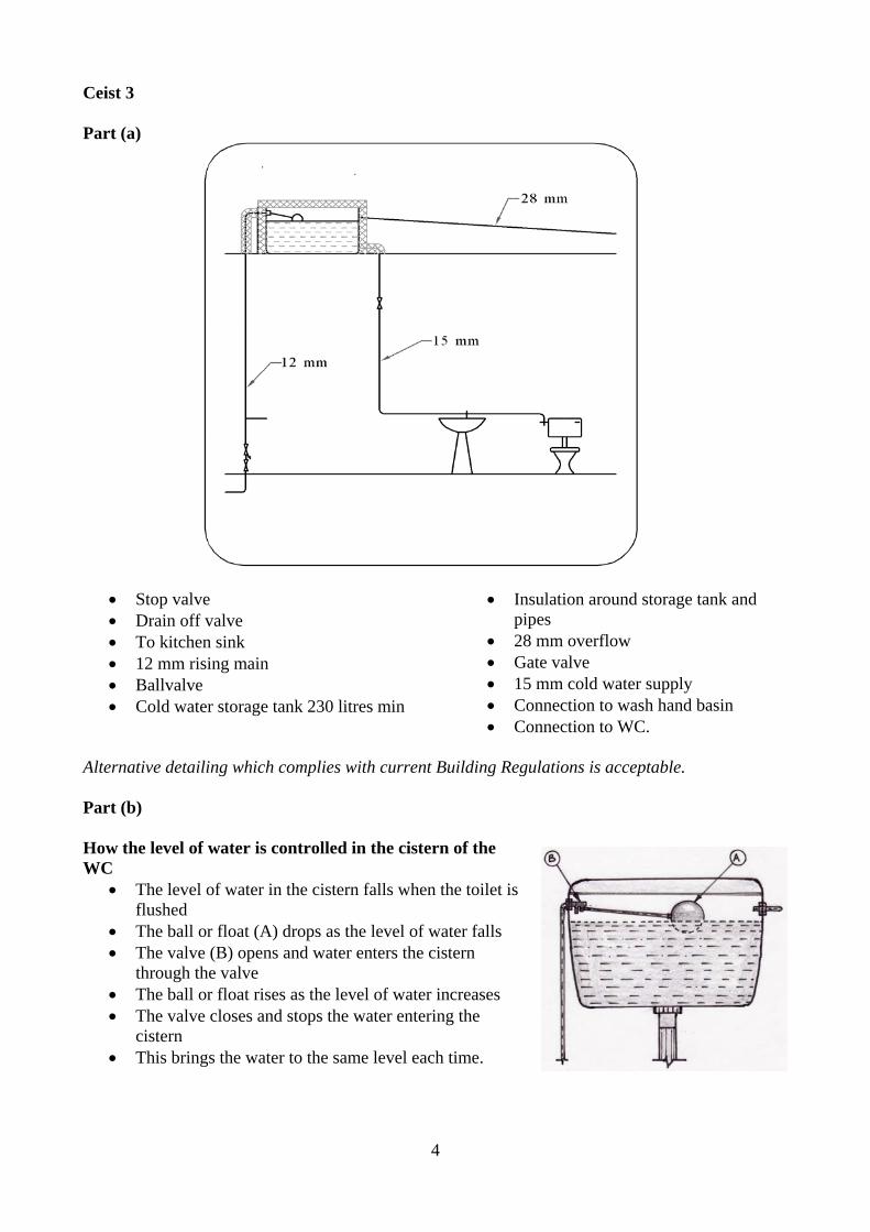
Ceist 3 Part (a)
• Stop valve • Drain off valve • To kitchen sink • 12 mm rising main • Ballvalve • Cold water storage tank 230 litres min
• Insulation around storage tank and pipes
• 28 mm overflow • Gate valve • 15 mm cold water supply • Connection to wash hand basin • Connection to WC.
Alternative detailing which complies with current Building Regulations is acceptable. Part (b) How the level of water is controlled in the cistern of the WC
• The level of water in the cistern falls when the toilet is flushed
• The ball or float (A) drops as the level of water falls • The valve (B) opens and water enters the cistern
through the valve • The ball or float rises as the level of water increases • The valve closes and stops the water entering the
cistern • This brings the water to the same level each time.
5
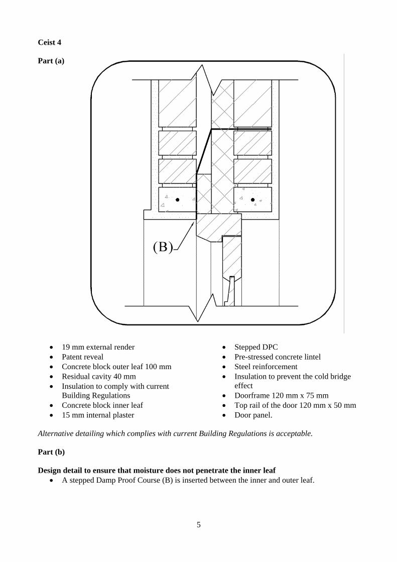
Ceist 4 Part (a)
• 19 mm external render • Patent reveal • Concrete block outer leaf 100 mm • Residual cavity 40 mm • Insulation to comply with current
Building Regulations • Concrete block inner leaf • 15 mm internal plaster
• Stepped DPC • Pre-stressed concrete lintel • Steel reinforcement • Insulation to prevent the cold bridge
effect • Doorframe 120 mm x 75 mm • Top rail of the door 120 mm x 50 mm • Door panel.
Alternative detailing which complies with current Building Regulations is acceptable. Part (b) Design detail to ensure that moisture does not penetrate the inner leaf
• A stepped Damp Proof Course (B) is inserted between the inner and outer leaf.
6
Ceist 5 Part (a) Reasons for planning permission
• Planning permission is a legal requirement • Planning permission informs the public about development • It regulates all new building work • It controls the height, shape, design and location of buildings • It prevents the danger of unsafe buildings • Proper regulation of sewage and waste disposal • Ensures that buildings are attractive and environmentally friendly • Ensures that buildings blend easily with their surroundings.
Part (b) Outline Planning Permission
• Outline permission is used to establish if the planning authority will agree to the development
• It is a general permission for the site • This is not concerned with the exact technical detailing of the development • Detailed drawings are not needed • This permission does not allow the development to proceed.
Examples of a situation where a person would use outline planning permission
• If a person or company is interested in the development of a site for building purposes • Outline planning increases the value of the property • Less documentation and less expense involved • No detailed plans needed • Application for outline permission gives a person an indication of how the planning
authority will approach the development. • Will find out if planning authorities have any difficulties with development – heritage, road
access, visual impact, percolation areas and proximity to other buildings… Part (c) Reasons for refusal
• The application does not comply with the development plan for the area • No prior consultation has been made with the planning authority • The proposed building will not blend in with existing built and natural environment • Once off development is not allowed on this site • Proper sewage treatment is not available • The site is not suitable for a private sewage treatment facility • The road is not suitable for extra traffic • The entrance could be unsafe for traffic and residents.
7
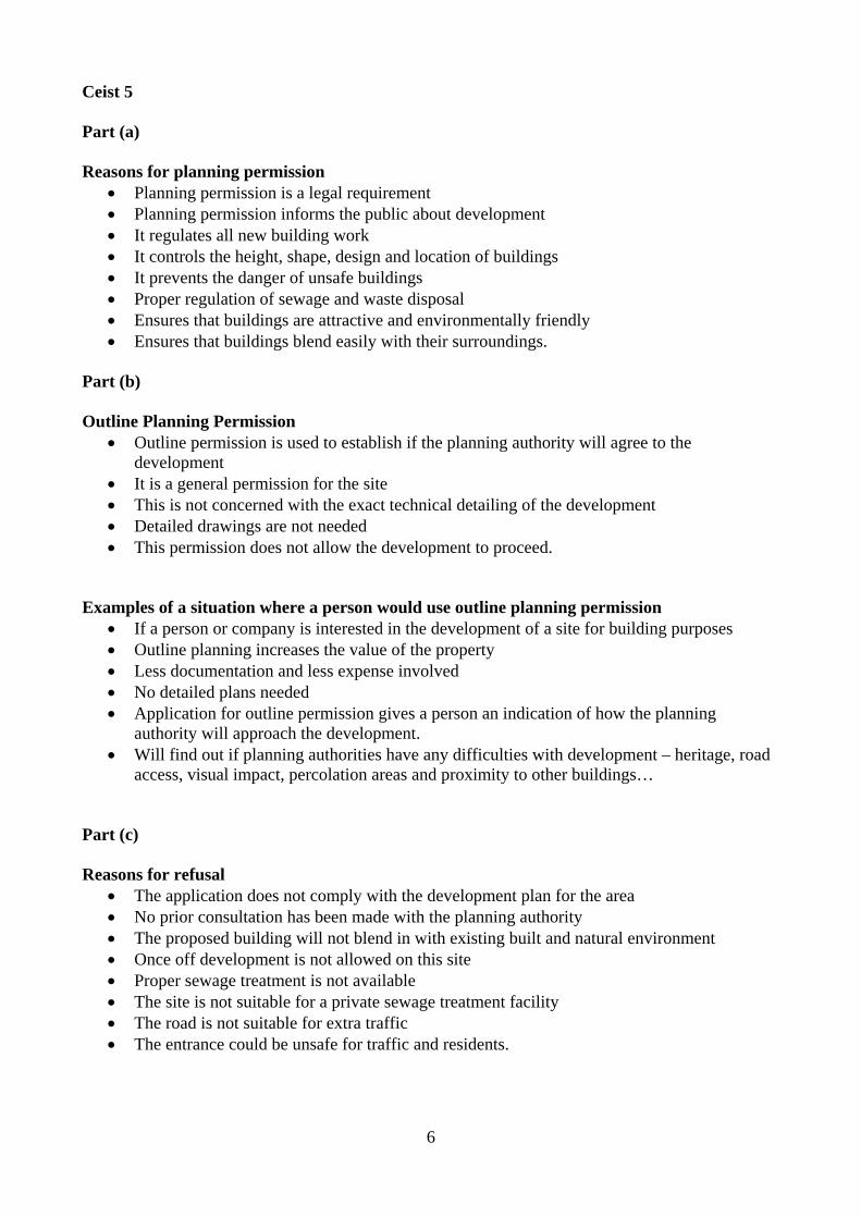
Ceist 6 Part (a) Rigid insulation board in the cavity of an external wall of concrete block construction
• The rigid insulation is fitted against the inner leaf of the cavity wall • The residual cavity is 40 mm • The typical thickness of the insulation is 60mm.
Part (b) Show how the insulation board is held in place
• The insulation board is held in place using specially designed wall ties
• The wall ties hold the board tight against the wall • The insulation boards are joined together using a tongue and groove
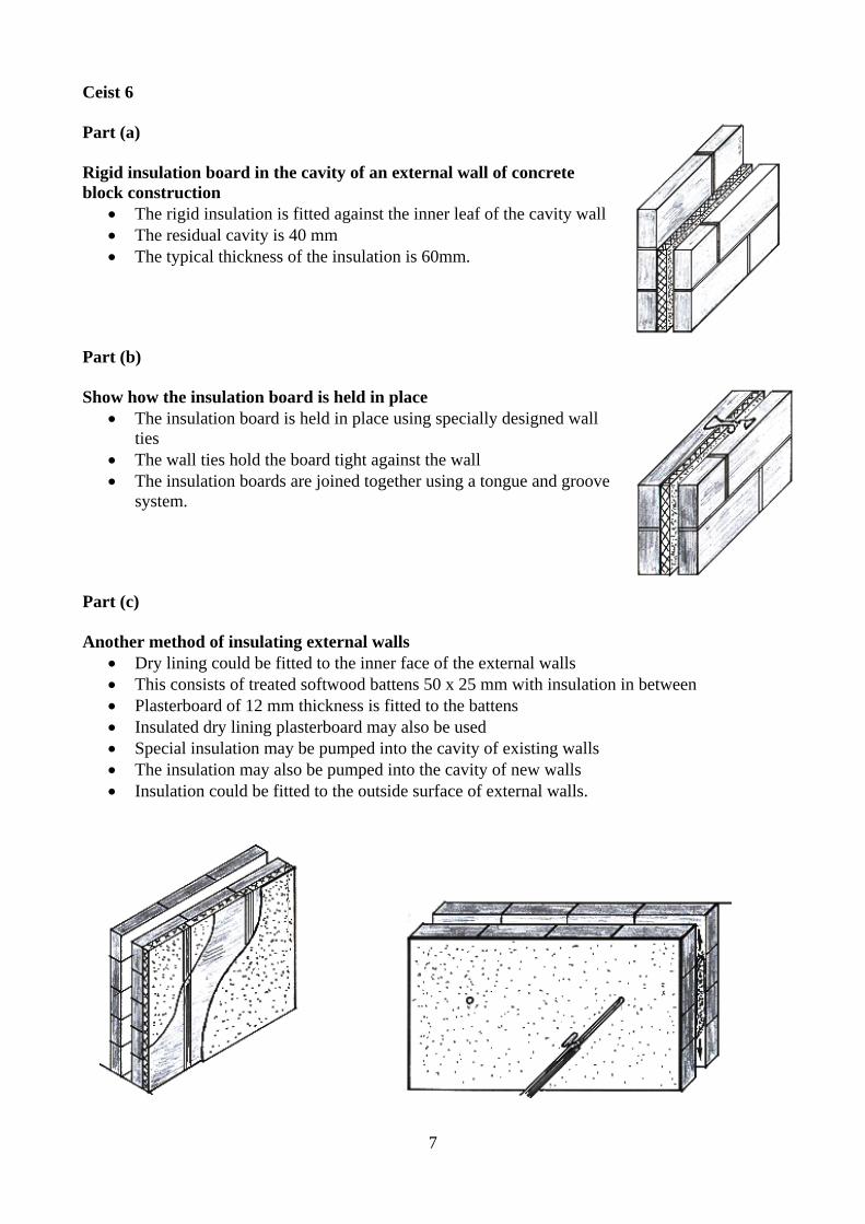
system. Part (c) Another method of insulating external walls
• Dry lining could be fitted to the inner face of the external walls • This consists of treated softwood battens 50 x 25 mm with insulation in between • Plasterboard of 12 mm thickness is fitted to the battens • Insulated dry lining plasterboard may also be used • Special insulation may be pumped into the cavity of existing walls • The insulation may also be pumped into the cavity of new walls • Insulation could be fitted to the outside surface of external walls.
8
Ceist 7 Part (a) Safety precautions to be observed when using a pillar drill
• Ensure the work is held securely • Wear eye protection • No loose clothing • Set the correct speed • Ensure the guard is in place at all times • Use the correct drill bit for the work being carried out.
Safety precautions to be observed when fitting a double glazed unit in a wooden window frame
• Be mindful of the sharp edges on the panel • Use gloves to protect hands • Wear a hard hat • Wear steel toe capped boots • Use suction pads where needed • Use a suitable bedding sealant • Use correct scaffolding where necessary • Get help if installing a large panel.
Safety precautions to be observed when using contact glue to fix veneer to a wooden panel
• Carry out the work in a well ventilated area • Keep the glue away from sources of ignition • Wear a mask and gloves • Read the instructions on the container • Do not inhale the fumes • Avoid contact with the skin • Keep out of the reach of children.
Part (b) Hard hat
• Must be worn by workers and visitors to the building site • Hard hat offers protection from falling objects.
Steel toe capped boots
• Must be worn by workers on the site • These protect the feet when working on a construction site.
High visibility jackets
• These jackets must be worn by all workers and visitors to the site • People are clearly visible on site when using these jackets.
9
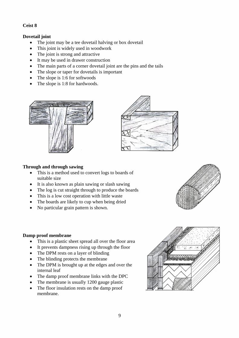
Ceist 8 Dovetail joint
• The joint may be a tee dovetail halving or box dovetail • This joint is widely used in woodwork • The joint is strong and attractive • It may be used in drawer construction • The main parts of a corner dovetail joint are the pins and the tails • The slope or taper for dovetails is important • The slope is 1:6 for softwoods • The slope is 1:8 for hardwoods.
Through and through sawing
• This is a method used to convert logs to boards of suitable size
• It is also known as plain sawing or slash sawing • The log is cut straight through to produce the boards • This is a low cost operation with little waste • The boards are likely to cup when being dried • No particular grain pattern is shown.
Damp proof membrane
• This is a plastic sheet spread all over the floor area • It prevents dampness rising up through the floor • The DPM rests on a layer of blinding • The blinding protects the membrane • The DPM is brought up at the edges and over the
internal leaf • The damp proof membrane links with the DPC • The membrane is usually 1200 gauge plastic • The floor insulation rests on the damp proof
membrane.
10
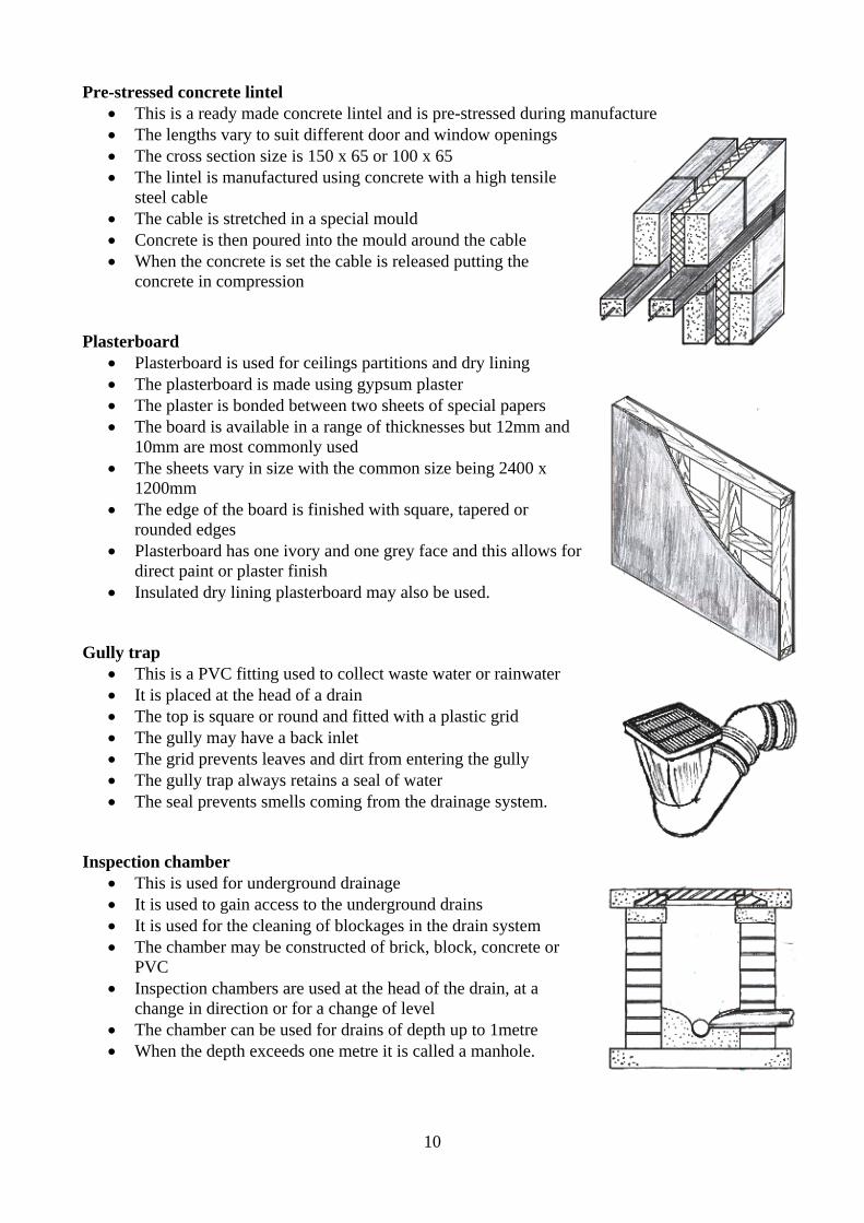
Pre-stressed concrete lintel • This is a ready made concrete lintel and is pre-stressed during manufacture • The lengths vary to suit different door and window openings • The cross section size is 150 x 65 or 100 x 65 • The lintel is manufactured using concrete with a high tensile
steel cable • The cable is stretched in a special mould • Concrete is then poured into the mould around the cable • When the concrete is set the cable is released putting the
concrete in compression Plasterboard
• Plasterboard is used for ceilings partitions and dry lining • The plasterboard is made using gypsum plaster • The plaster is bonded between two sheets of special papers • The board is available in a range of thicknesses but 12mm and
10mm are most commonly used • The sheets vary in size with the common size being 2400 x
1200mm • The edge of the board is finished with square, tapered or
rounded edges • Plasterboard has one ivory and one grey face and this allows for
direct paint or plaster finish • Insulated dry lining plasterboard may also be used.
Gully trap
• This is a PVC fitting used to collect waste water or rainwater • It is placed at the head of a drain • The top is square or round and fitted with a plastic grid • The gully may have a back inlet • The grid prevents leaves and dirt from entering the gully • The gully trap always retains a seal of water • The seal prevents smells coming from the drainage system.
Inspection chamber
• This is used for underground drainage • It is used to gain access to the underground drains • It is used for the cleaning of blockages in the drain system • The chamber may be constructed of brick, block, concrete or
PVC • Inspection chambers are used at the head of the drain, at a
change in direction or for a change of level • The chamber can be used for drains of depth up to 1metre • When the depth exceeds one metre it is called a manhole.
11
Ceist 9 Part (a) Suitable woods for the external cladding
• Cedar • Larch • Red deal or Scots pine • Any pressure impregnated softwood.
Reasons for choice of wood Cedar
• Ideal for outdoor as it is very resistant to decay • Easy to work and glue together • Pleasant appearance • Easily finished with oil or other suitable treatment • It is lightweight making it suitable for cladding.
Larch
• Naturally durable for outdoor use • Looks well with red heartwood • Is easily grown in Ireland • It is resistant to water.
Red deal or Scots pine
• Easy to cut and work • Provides a good finish when painted or varnished • Reasonably priced • Strong durable and stable.
Part (b) Suitable applied finish to help preserve the cladding
• A wide range of oil based finishes is available • These are available from well known manufacturers • They are supplied under the headings such as Deck oil or Fence life • They are available in a range of colours • Water based finishes are also available • Any of these are suitable as an applied finish for the cladding • These finishes will preserve the wood.

12
Steps involved in applying the finish
• Ensure the wood is clean and dry • Sand lightly and clean with white spirits • Apply the finish using a good quality brush • Apply even coats and finish in the direction of the grain • Apply three coats and sand lightly between coats.
Part (c) Design feature that helps protect the cladding from the effects of weather
• The roof projects out to the front • This protects the cladding from sunlight and rain • The gable end or barge of the roof projects out over the gable wall • This design detail helps protect the cladding from the effects of the weather • Lap at the joint of the board - shiplap • Any other suitable design feature.
13
Staidéar Foirgníochta Teoiric – Gnáthleibhéal Scéim Mharcála
Construction Studies Theory – Ordinary Level Marking Scheme
Coimisiún na Scrúduithe Stáit State Examinations Commission
14
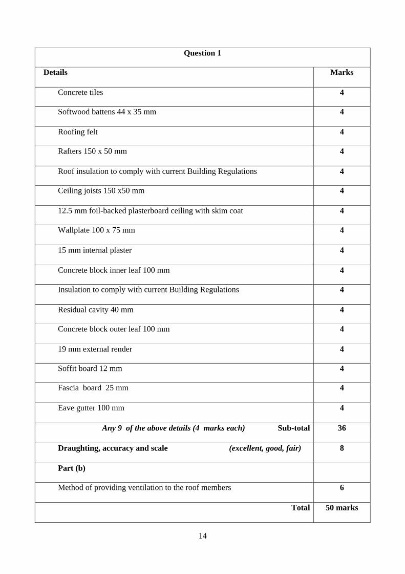
Question 1
Details Marks
Concrete tiles 4
Softwood battens 44 x 35 mm 4
Roofing felt 4
Rafters 150 x 50 mm 4
Roof insulation to comply with current Building Regulations 4
Ceiling joists 150 x50 mm 4
12.5 mm foil-backed plasterboard ceiling with skim coat 4
Wallplate 100 x 75 mm 4
15 mm internal plaster 4
Concrete block inner leaf 100 mm 4
Insulation to comply with current Building Regulations 4
Residual cavity 40 mm 4
Concrete block outer leaf 100 mm 4
19 mm external render 4
Soffit board 12 mm 4
Fascia board 25 mm 4
Eave gutter 100 mm 4
Any 9 of the above details (4 marks each) Sub-total 36
Draughting, accuracy and scale (excellent, good, fair) 8
Part (b)
Method of providing ventilation to the roof members 6
Total 50 marks
15
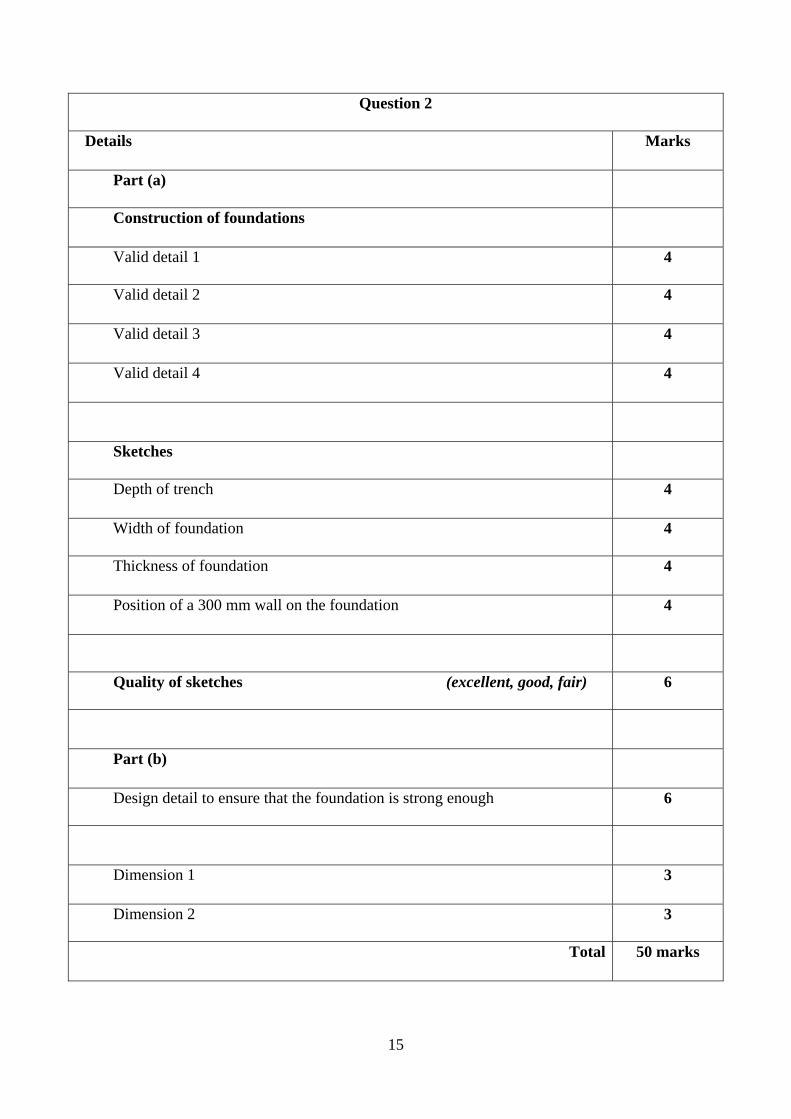
Question 2
Details Marks
Part (a)
Construction of foundations
Valid detail 1 4
Valid detail 2 4
Valid detail 3 4
Valid detail 4 4
Sketches
Depth of trench 4
Width of foundation 4
Thickness of foundation 4
Position of a 300 mm wall on the foundation 4
Quality of sketches (excellent, good, fair) 6
Part (b)
Design detail to ensure that the foundation is strong enough 6
Dimension 1 3
Dimension 2 3
Total 50 marks
16
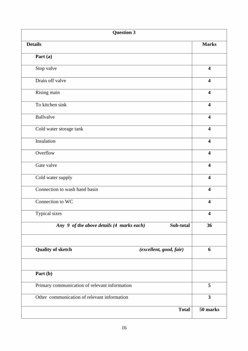
Question 3
Details Marks
Part (a)
Stop valve 4
Drain off valve 4
Rising main 4
To kitchen sink 4
Ballvalve 4
Cold water storage tank 4
Insulation 4
Overflow 4
Gate valve 4
Cold water supply 4
Connection to wash hand basin 4
Connection to WC 4
Typical sizes 4
Any 9 of the above details (4 marks each) Sub-total 36
Quality of sketch (excellent, good, fair) 6
Part (b)
Primary communication of relevant information 5
Other communication of relevant information 3
Total 50 marks
17
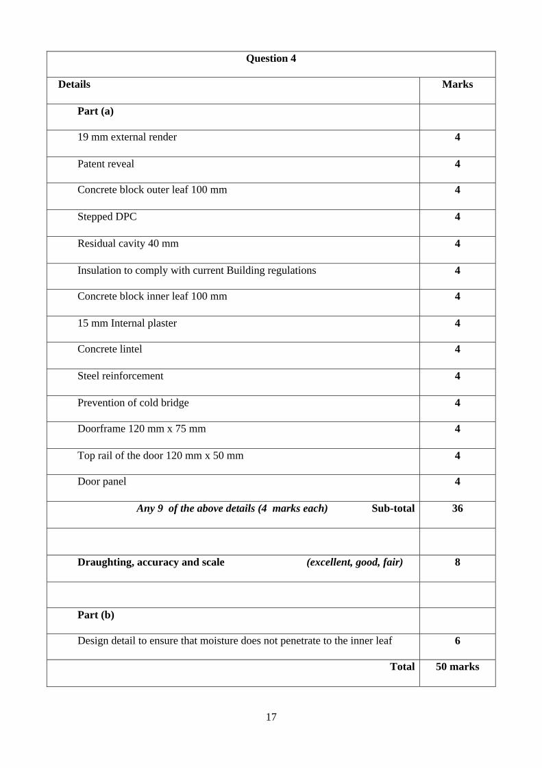
Question 4
Details Marks
Part (a)
19 mm external render 4
Patent reveal 4
Concrete block outer leaf 100 mm 4
Stepped DPC 4
Residual cavity 40 mm 4
Insulation to comply with current Building regulations 4
Concrete block inner leaf 100 mm 4
15 mm Internal plaster 4
Concrete lintel 4
Steel reinforcement 4
Prevention of cold bridge 4
Doorframe 120 mm x 75 mm 4
Top rail of the door 120 mm x 50 mm 4
Door panel 4
Any 9 of the above details (4 marks each) Sub-total 36
Draughting, accuracy and scale (excellent, good, fair) 8
Part (b)
Design detail to ensure that moisture does not penetrate to the inner leaf 6
Total 50 marks
18
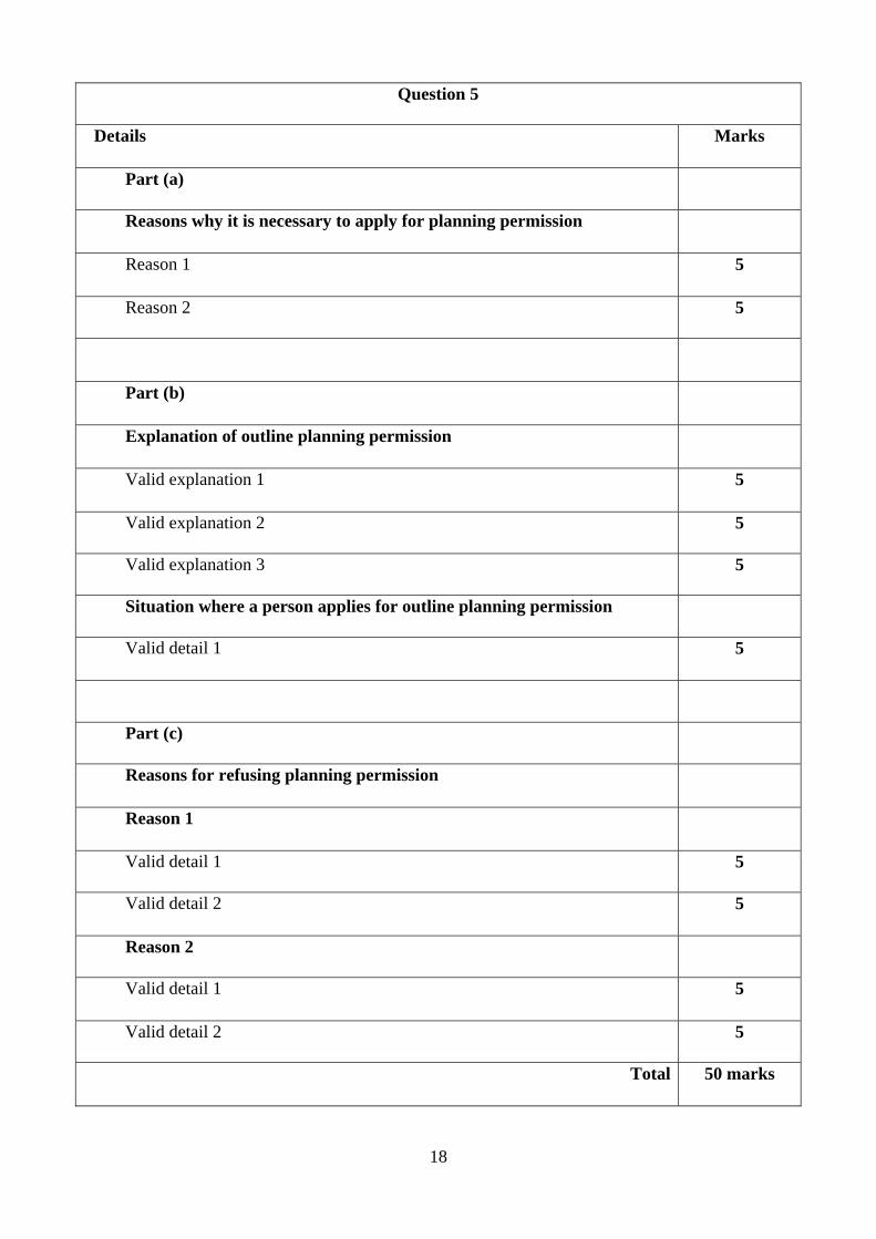
Question 5
Details Marks
Part (a)
Reasons why it is necessary to apply for planning permission
Reason 1 5
Reason 2 5
Part (b)
Explanation of outline planning permission
Valid explanation 1 5
Valid explanation 2 5
Valid explanation 3 5
Situation where a person applies for outline planning permission
Valid detail 1 5
Part (c)
Reasons for refusing planning permission
Reason 1
Valid detail 1 5
Valid detail 2 5
Reason 2
Valid detail 1 5
Valid detail 2 5
Total 50 marks

19
Question 6
Details Marks
Part (a)
Location of a rigid insulation in the cavity of an external wall
Sketch
Outer and Inner leaf of wall 4
Cavity 4
Insulation 4
Quality of sketch (excellent, good, fair) 6
Typical thickness of the insulation board 4
Notes
Valid detail 1 4
Valid detail 2 4
Part (b)
Holding the insulation board in place in the cavity
Primary communication of relevant information 6
Other communication of relevant information 4
Part (c)
Another method of insulating the external wall of the house
Primary communication of relevant information 6
Other communication of relevant information 4
Total 50 marks
20
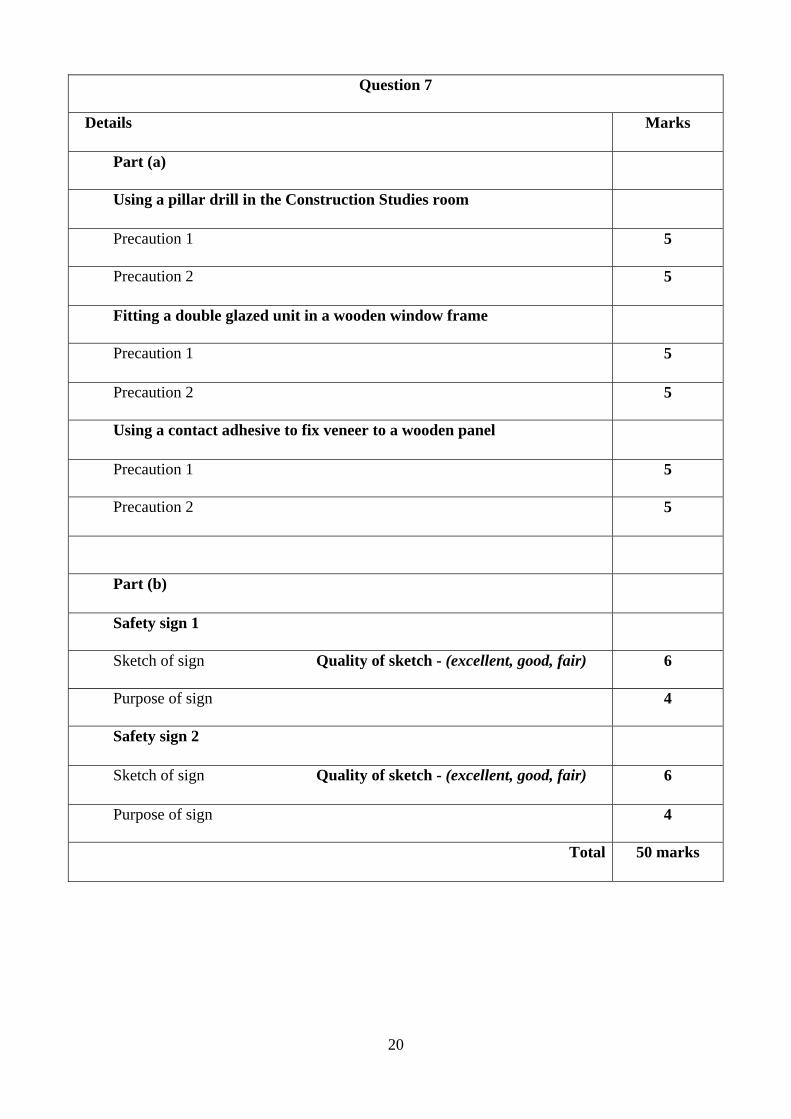
Question 7
Details Marks
Part (a)
Using a pillar drill in the Construction Studies room
Precaution 1 5
Precaution 2 5
Fitting a double glazed unit in a wooden window frame
Precaution 1 5
Precaution 2 5
Using a contact adhesive to fix veneer to a wooden panel
Precaution 1 5
Precaution 2 5
Part (b)
Safety sign 1
Sketch of sign Quality of sketch - (excellent, good, fair) 6
Purpose of sign 4
Safety sign 2
Sketch of sign Quality of sketch - (excellent, good, fair) 6
Purpose of sign 4
Total 50 marks

21
Question 8
Details Marks
Item number 1
Primary communication of relevant information 6
Other communication of relevant information 4
Item number 2
Primary communication of relevant information 6
Other communication of relevant information 4
Item number 3
Primary communication of relevant information 6
Other communication of relevant information 4
Item number 4
Primary communication of relevant information 6
Other communication of relevant information 4
Item number 5
Primary communication of relevant information 6
Other communication of relevant information 4
Total 50 marks

22
Question 9
Details Marks
Part (a)
Suitable wood 3
Reasons for choice of wood
Valid reason 1 4
Valid reason 2 4
Part (b)
Suitable applied finish 3
Notes - Applying the finish
Stage 1 – Preparation repair and cleaning 4
Stage 2 – Filling and sanding 4
Stage 3 – Brush application of finish 4
Stage 4 – Light sanding and final coat 4
Sketches - Applying the finish
Any suitable sketch 4
Quality of sketch (excellent, good, fair) 6
Part (c)
Design detail to help protect the cladding from the weather
Primary communication of relevant detail 6
Other communication of relevant detail 4
Total 50 marks
LEAVING CERTIFICATE 2008
MARKING SCHEME
CONSTRUCTION STUDIES –
Practical Test
1
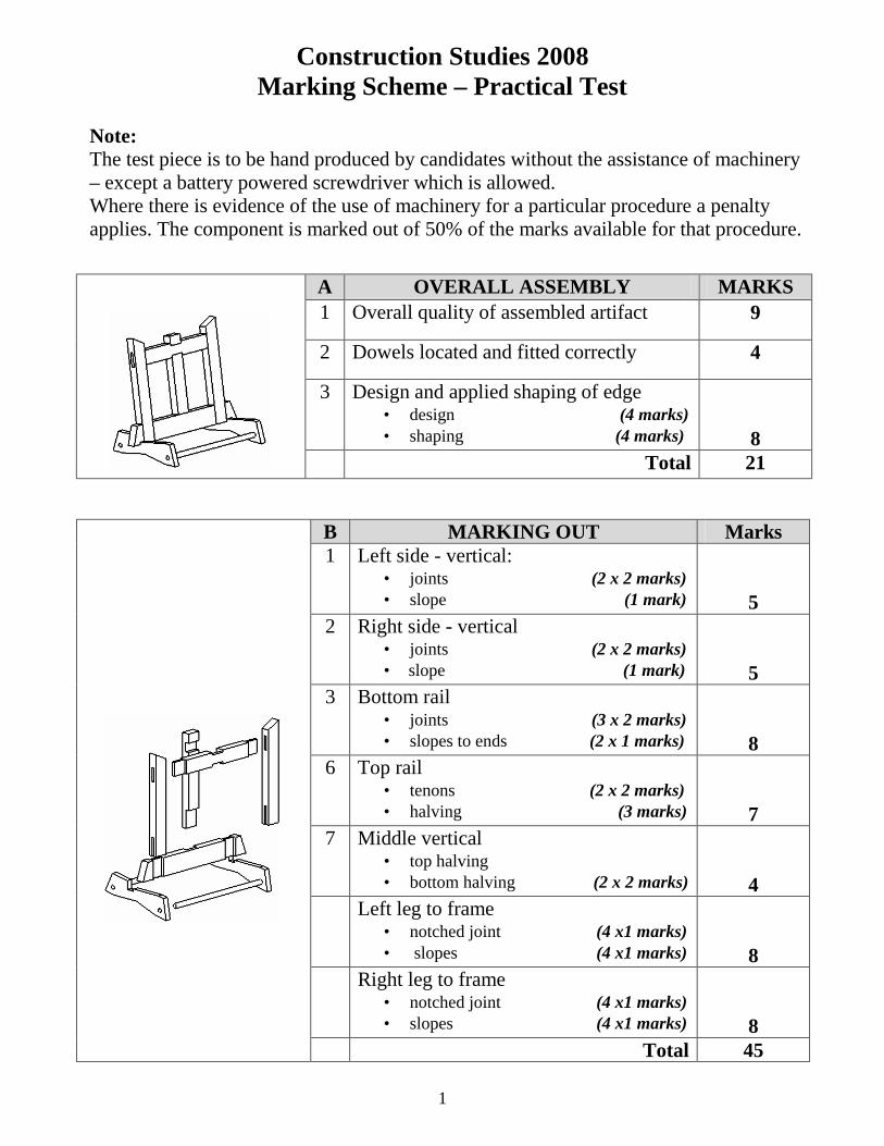
Construction Studies 2008 Marking Scheme – Practical Test
Note: The test piece is to be hand produced by candidates without the assistance of machinery – except a battery powered screwdriver which is allowed. Where there is evidence of the use of machinery for a particular procedure a penalty applies. The component is marked out of 50% of the marks available for that procedure.
B MARKING OUT Marks 1 Left side - vertical:
• joints (2 x 2 marks) • slope (1 mark)
5 2 Right side - vertical
• joints (2 x 2 marks) • slope (1 mark)
5 3 Bottom rail
• joints (3 x 2 marks) • slopes to ends (2 x 1 marks)
8 6 Top rail
• tenons (2 x 2 marks) • halving (3 marks)
7 7 Middle vertical
• top halving • bottom halving (2 x 2 marks)
4 Left leg to frame
• notched joint (4 x1 marks) • slopes (4 x1 marks)
8 Right leg to frame
• notched joint (4 x1 marks) • slopes (4 x1 marks)
8
Total 45
A OVERALL ASSEMBLY MARKS 1 Overall quality of assembled artifact 9
2 Dowels located and fitted correctly 4
3 Design and applied shaping of edge • design (4 marks) • shaping (4 marks)
8
Total 21
2
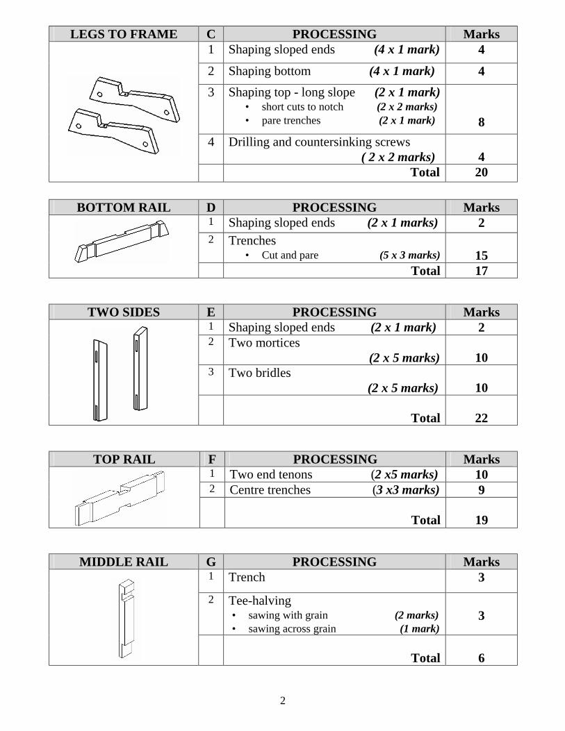
LEGS TO FRAME C PROCESSING Marks 1 Shaping sloped ends (4 x 1 mark) 4 2 Shaping bottom (4 x 1 mark) 4 3 Shaping top - long slope (2 x 1 mark)
• short cuts to notch (2 x 2 marks) • pare trenches (2 x 1 mark)
8 4 Drilling and countersinking screws
( 2 x 2 marks)
4
Total 20
BOTTOM RAIL D PROCESSING Marks 1 Shaping sloped ends (2 x 1 marks) 2 2 Trenches
• Cut and pare (5 x 3 marks)
15
Total 17
TWO SIDES E PROCESSING Marks 1 Shaping sloped ends (2 x 1 mark) 2 2 Two mortices
(2 x 5 marks)
10 3 Two bridles
(2 x 5 marks)
10
Total
22
TOP RAIL F PROCESSING Marks 1 Two end tenons (2 x5 marks) 10 2 Centre trenches (3 x3 marks) 9
Total
19
MIDDLE RAIL G PROCESSING Marks 1 Trench 3 2 Tee-halving
• sawing with grain (2 marks) • sawing across grain (1 mark)
3
Total
6