Leaky Waveguide Antenna Design Methodology
15
Daniel Rogers Duotech Services, Inc. Leaky Waveguide Antenna Design Methodology Computational Electromagnetics, Testing, Construction, and Lessons Learned
Transcript of Leaky Waveguide Antenna Design Methodology
Daniel Rogers Duotech Services, Inc.
Leaky Waveguide Antenna Design Methodology
Computational Electromagnetics, Testing, Construction, and Lessons Learned
Overview
❖ Purpose
❖ Approach
❖ Prerequisite Information
❖ Methods
❖ Analysis
❖ Synthesis
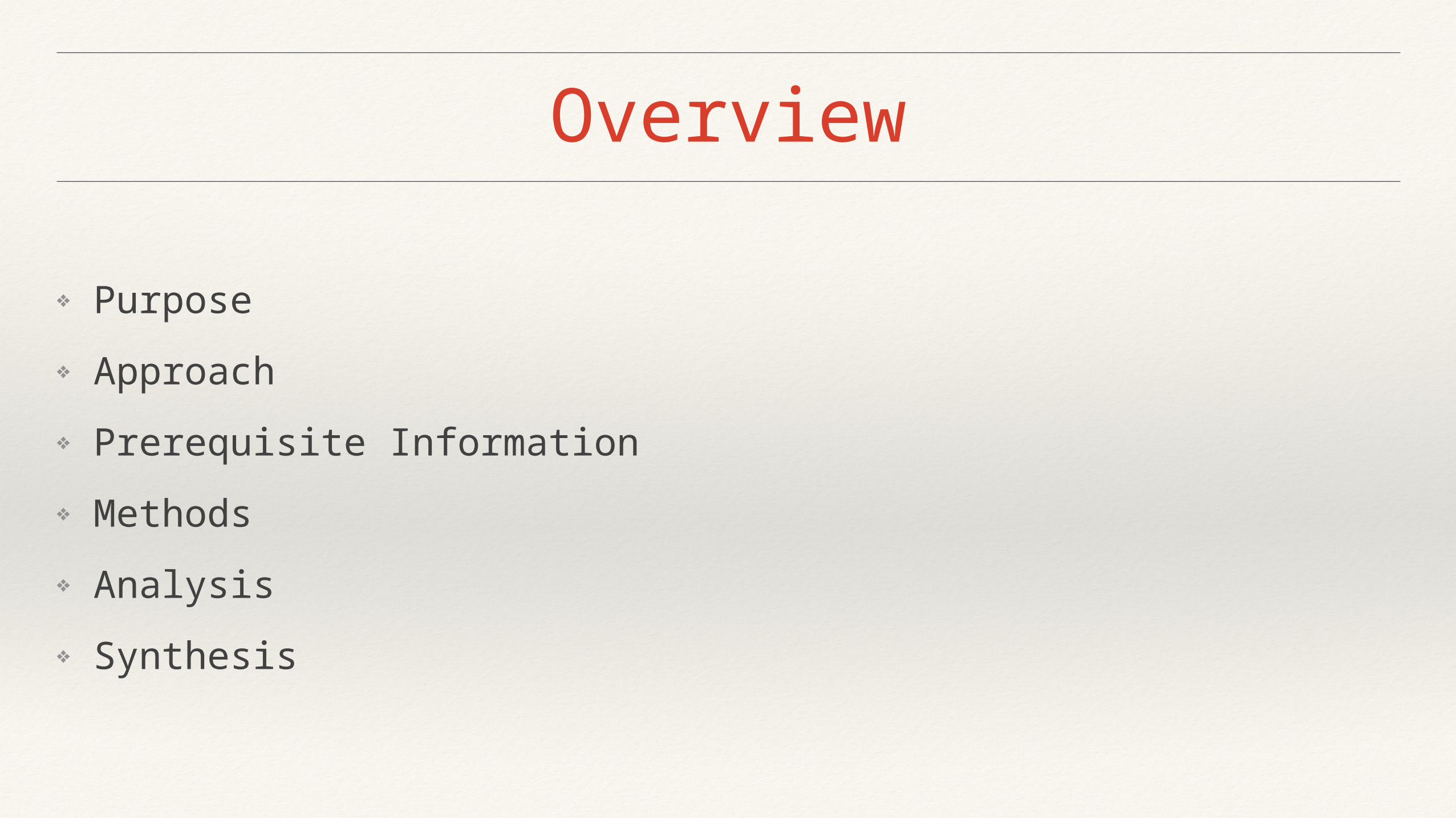
Purpose
❖ Develop a highly directional antenna
❖ 35dBi gain
❖ Less than 2 degree 3dB beam width
❖ Analyze potential design
❖ Synthesize a manufacturable approach
❖ Analysis of actual design before and after production
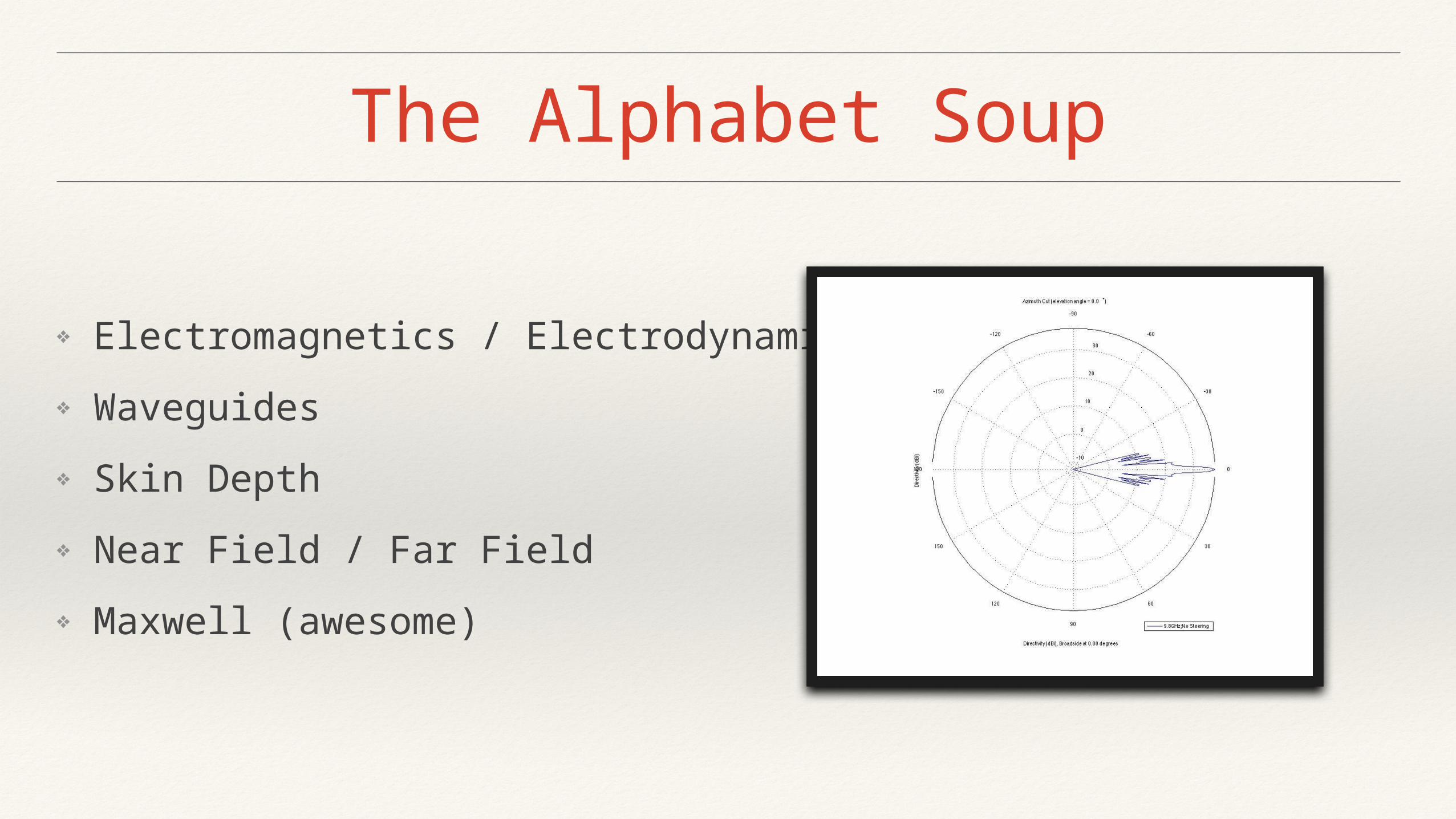
The Alphabet Soup
❖ Electromagnetics / Electrodynamics
❖ Waveguides
❖ Skin Depth
❖ Near Field / Far Field
❖ Maxwell (awesome)
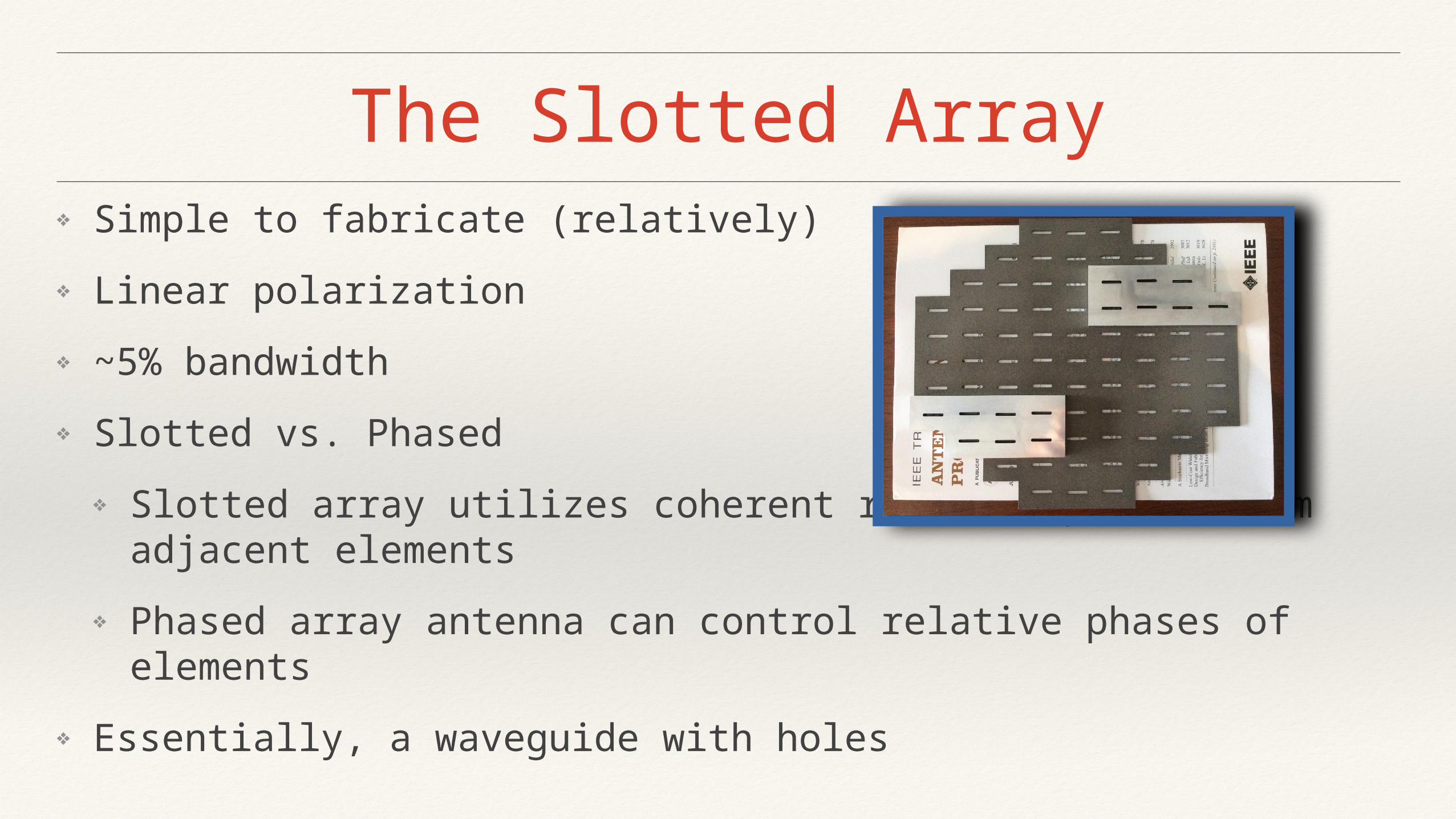
The Slotted Array❖ Simple to fabricate (relatively)
❖ Linear polarization
❖ ~5% bandwidth
❖ Slotted vs. Phased
❖ Slotted array utilizes coherent relative phases from adjacent elements
❖ Phased array antenna can control relative phases of elements
❖ Essentially, a waveguide with holes
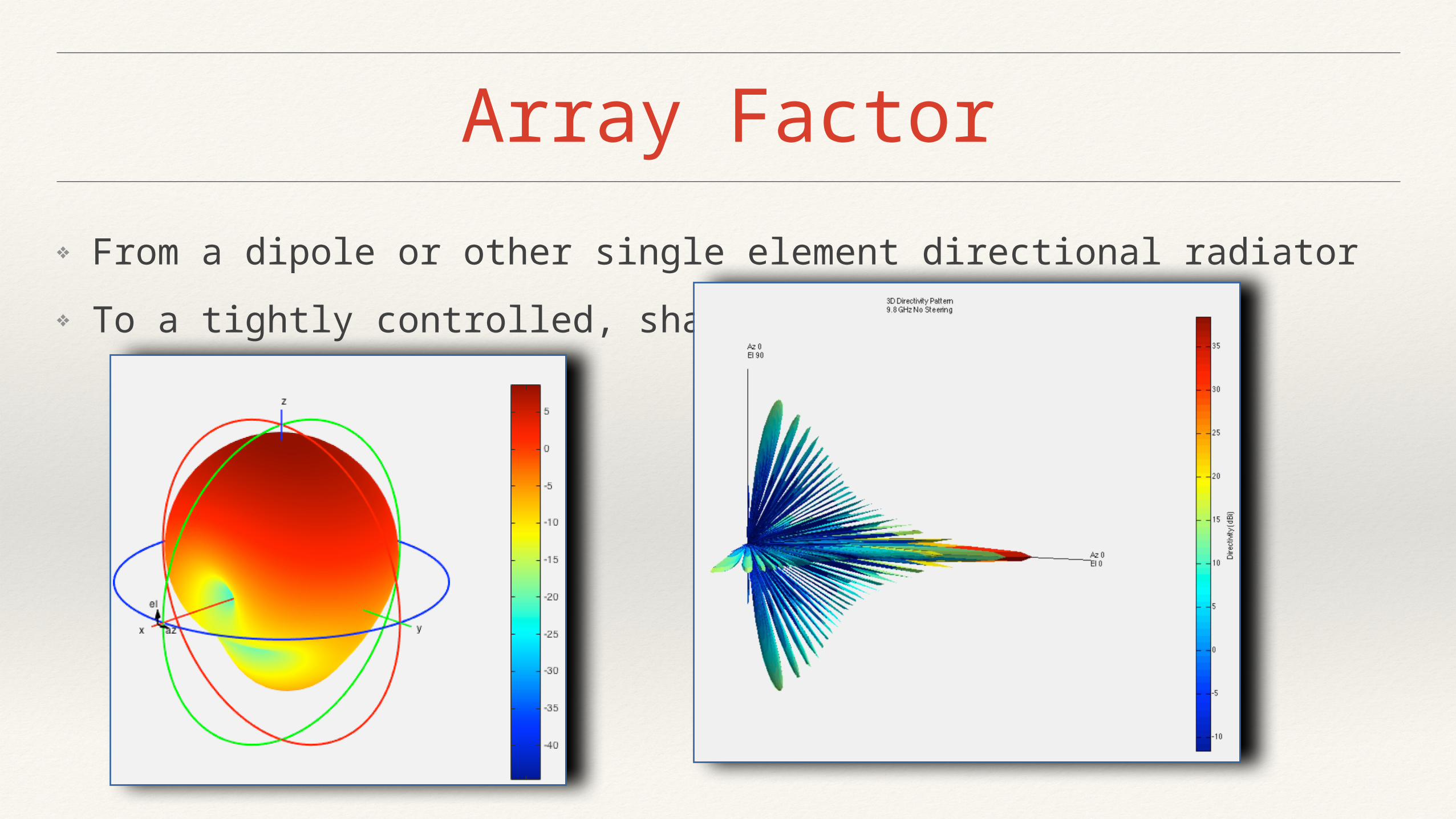
Array Factor
❖ From a dipole or other single element directional radiator
❖ To a tightly controlled, sharp beam
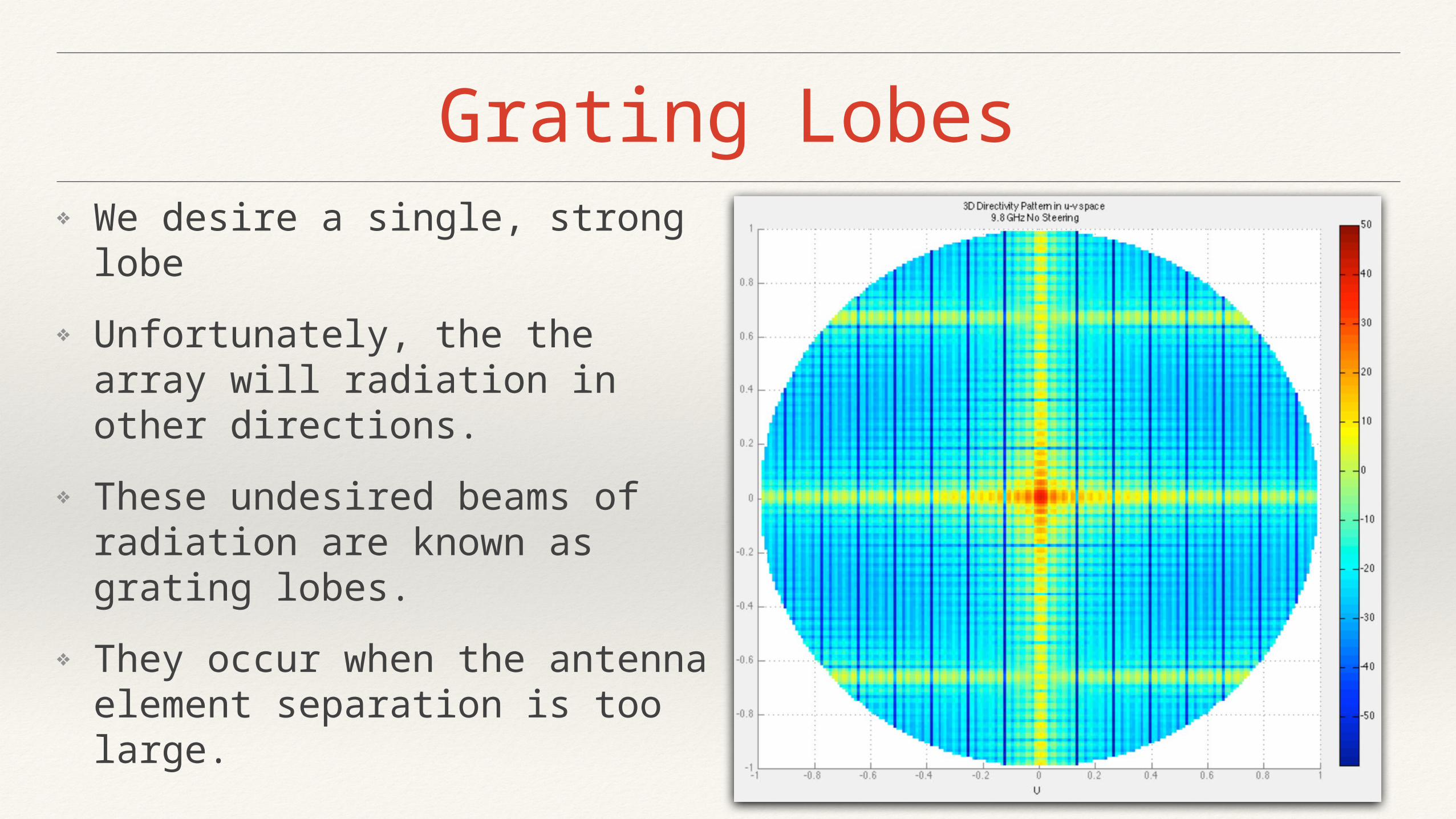
Grating Lobes
❖ We desire a single, strong lobe
❖ Unfortunately, the the array will radiation in other directions.
❖ These undesired beams of radiation are known as grating lobes.
❖ They occur when the antenna element separation is too large.
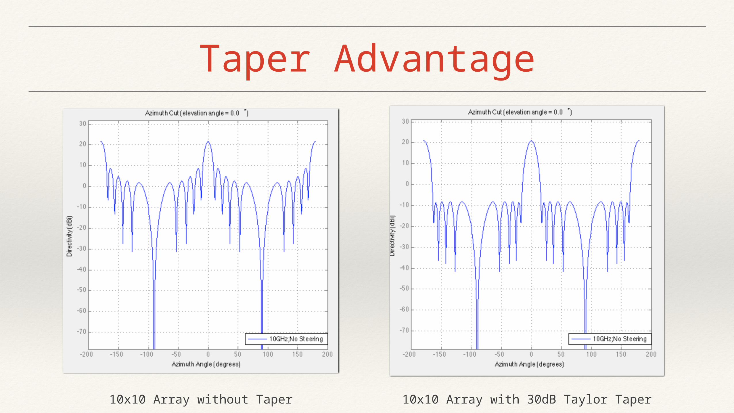
Taper Advantage
10x10 Array without Taper 10x10 Array with 30dB Taylor Taper
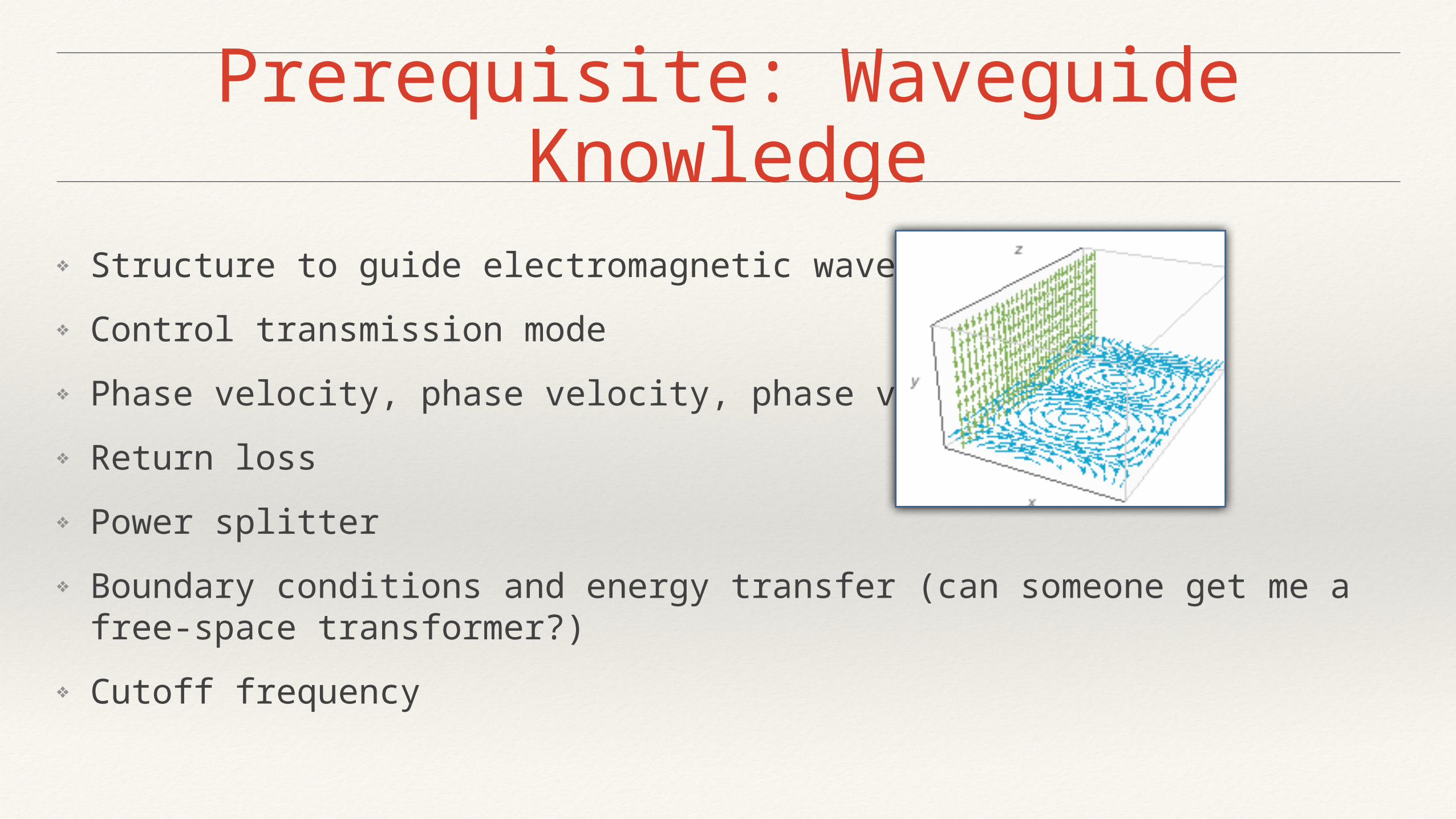
Prerequisite: Waveguide Knowledge
❖ Structure to guide electromagnetic waves
❖ Control transmission mode
❖ Phase velocity, phase velocity, phase velocity!
❖ Return loss
❖ Power splitter
❖ Boundary conditions and energy transfer (can someone get me a free-space transformer?)
❖ Cutoff frequency
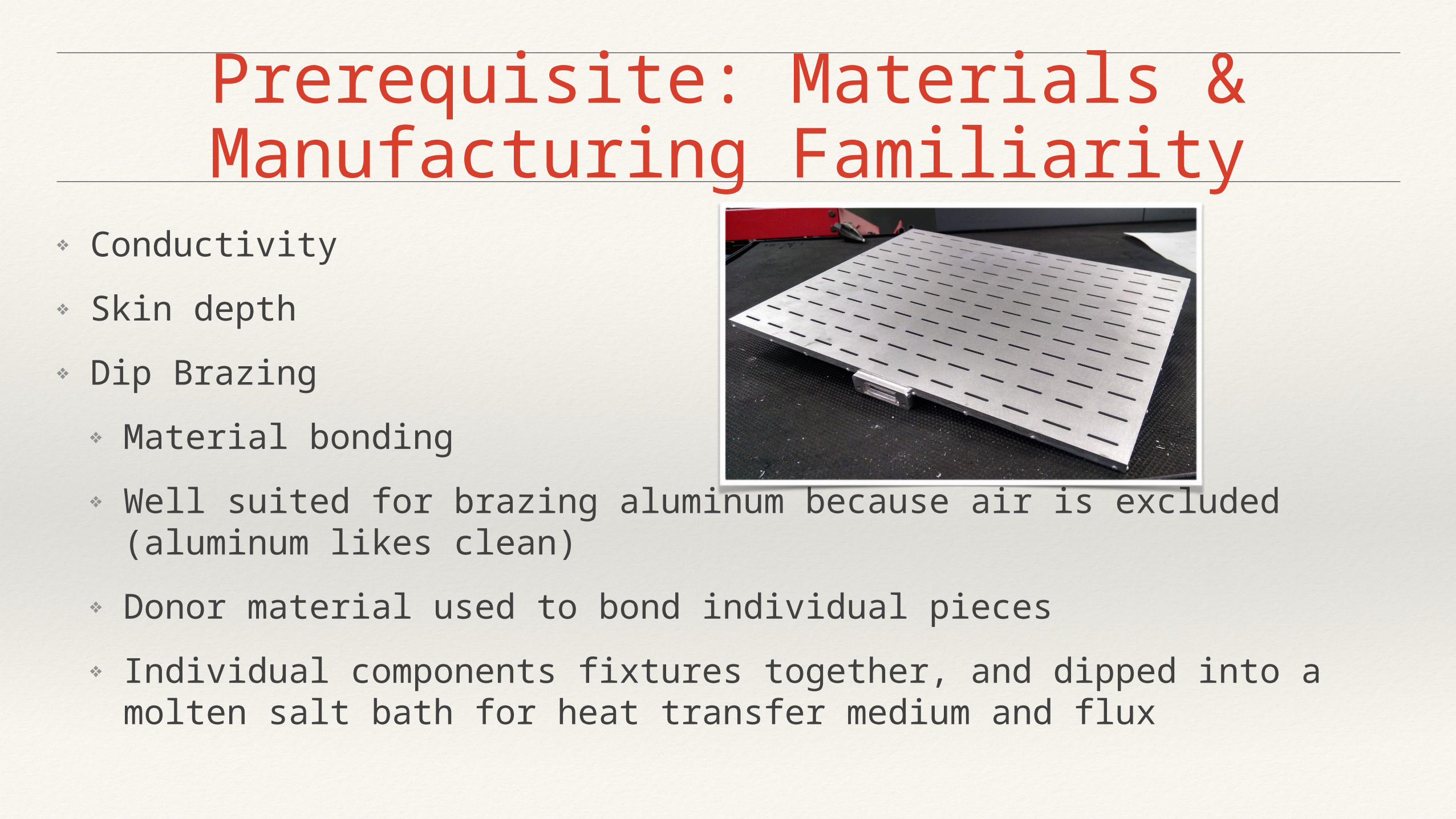
Prerequisite: Materials & Manufacturing Familiarity
❖ Conductivity
❖ Skin depth
❖ Dip Brazing
❖ Material bonding
❖ Well suited for brazing aluminum because air is excluded (aluminum likes clean)
❖ Donor material used to bond individual pieces
❖ Individual components fixtures together, and dipped into a molten salt bath for heat transfer medium and flux
Simulation
❖ Investigated Approaches
❖ Differential equation solvers: Finite-difference time-domain
❖ Integral equation solvers: Method of moments (MoM)
❖ Other: EigenMode Expansion (EME)
❖ MATLAB®
❖ Various toolboxes
❖ Approaches: MoM, FDTD
❖ MathCAD®
❖ General Calculations
❖ MoM
Testing
❖ Near field
❖ Concept
❖ Flaws
❖ Far field
❖ Requires a large space
❖ Far field begins at ~116’ for this antenna
❖ Tools
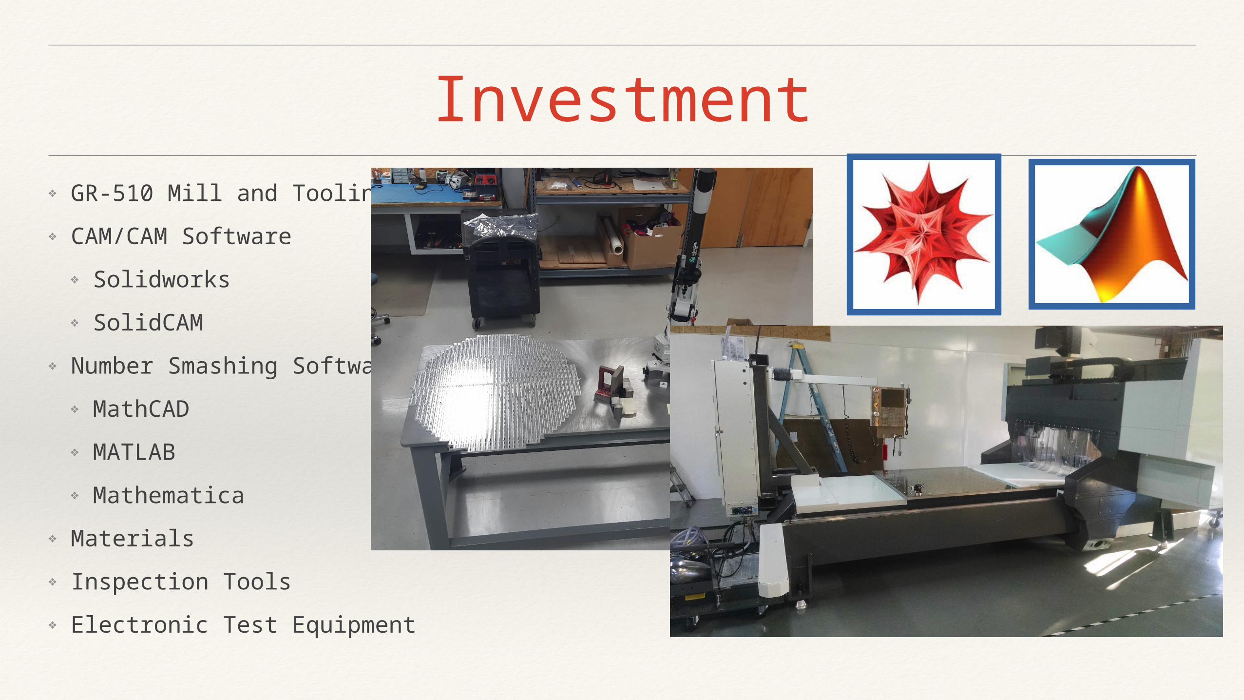
Investment❖ GR-510 Mill and Tooling
❖ CAM/CAM Software
❖ Solidworks
❖ SolidCAM
❖ Number Smashing Software
❖ MathCAD
❖ MATLAB
❖ Mathematica
❖ Materials
❖ Inspection Tools
❖ Electronic Test Equipment
Lessons Learned
❖ Loughborough Antennas & Propagation Conference very worth while
❖ Possible to design with strong Electromagnetics, O.D.E, and Linear Algebra skills
❖ Knowledge about this design on IEEE Explore does not exist within any one document
❖ An EM solver tool would have been worth while to use in retrospect (e.g. Feko®, CST®, Comsol®)
❖ White boards are better than Mathematica® for this application
All rights reserved Duotech Services, Inc. 2015
Questions?


![Waveguide Slot Filtering Antenna with Metamaterial Surface · 2018. 10. 19. · waveguide divider for broadenning the bandwidth of a waveguide slot antenna array [4]-[5] offers a](https://static.fdocuments.net/doc/165x107/60af47a44dbd540ffb16c382/waveguide-slot-filtering-antenna-with-metamaterial-surface-2018-10-19-waveguide.jpg)