Layout Design - Midmark
16
For product inquiries, please contact Midmark Dental Customer Service at 1-800-MIDMARK. For more information or a demonstration, contact Midmark, 60 Vista Drive, P.O. Box 286, Versailles, Ohio 45380-0286. Call: 1-800-MIDMARK Fax: 1-877-725-6495 midmark.com Midmark Equipment Room Layout Design
Transcript of Layout Design - Midmark
For product inquiries, please contact Midmark Dental Customer Service at 1-800-MIDMARK. For more information or a demonstration, contact Midmark, 60 Vista Drive, P.O. Box 286, Versailles, Ohio 45380-0286. Call: 1-800-MIDMARK Fax: 1-877-725-6495 midmark.com
Midmark Equipment Room Layout Design
© Midmark Corporation 2006 1 004-0519-00 Rev. F SF-1890
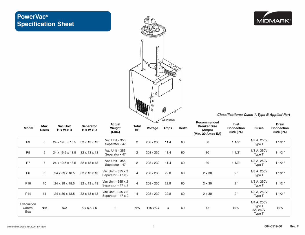
PowerVac®
Specification Sheet
Classifications: Class 1, Type B Applied Part
ModelMax
UsersVac Unit
H x W x DSeparatorH x W x D
ActualWeight(LBS.)
TotalHP Voltage Amps Hertz
RecommendedBreaker Size
(Amps)(Min. 20 Amps EA)
InletConnection
Size (IN.)Fuses
DrainConnection
Size (IN.)
P3 3 24 x 19.5 x 18.5 32 x 13 x 13Vac Unit - 355Separator - 47
2 208 / 230 11.4 60 30 1 1/2"1/8 A, 250V
Type T1 1/2 "
P5 5 24 x 19.5 x 18.5 32 x 13 x 13Vac Unit - 355Separator - 47
2 208 / 230 11.4 60 30 1 1/2"1/8 A, 250V
Type T1 1/2 "
P7 7 24 x 19.5 x 18.5 32 x 13 x 13Vac Unit - 355Separator - 47
2 208 / 230 11.4 60 30 1 1/2"1/8 A, 250V
Type T1 1/2 "
P6 6 24 x 39 x 18.5 32 x 13 x 13Vac Unit - 355 x 2Separator - 47 x 2
4 208 / 230 22.8 60 2 x 30 2"1/8 A, 250V
Type T1 1/2 "
P10 10 24 x 39 x 18.5 32 x 13 x 13Vac Unit - 355 x 2Separator - 47 x 2
4 208 / 230 22.8 60 2 x 30 2"1/8 A, 250V
Type T1 1/2 "
P14 14 24 x 39 x 18.5 32 x 13 x 13Vac Unit - 355 x 2Separator - 47 x 2
4 208 / 230 22.8 60 2 x 30 2"1/8 A, 250V
Type T1 1/2 "
EvacuationControl
BoxN/A N/A 5 x 5.5 x 6 2 N/A 115 VAC 3 60 15 N/A
1/4 A, 250VType T
3A, 250VType T
N/A
AA155101i
0
5
10
1520
25
-30

© Midmark Corporation 2006 SF-1890
PowerVac®Site Requirements
PLUMBING
• EXHAUST LINE Single Models P3, P5, P7 Twin Models P6, P10, P14
TypePVC Sch 40, CPVC Sch 80, Copper or
Galvanized SteelCPVC Sch 80, Copper or Galvanized Steel
Size1-1/2" for up to 15' exhaust line length
2" for greater than 15' exhaust line length2" for all exhaust line lengths
Termination 1 1/2" NPT Male Pipe
• INTAKE (SUCTION) LINE Single Models P3, P5, P7 Twin Models P6, P10, P14
Type PVC Sch 40 Pipe Recommended - for Main Trunk and Branch Lines
Line Sizing Refer to: "Site Requirement Layout", located in this document.
Pump Termination 1-1/2" 2"
• DRAIN Single Models P3, P5, P7 Twin Models P6, P10, P14
Type Floor Drain or 1 1/2" PVC Sch 40 P-Trap
Flow Capacity Minimum 25 Gallons per Minute
Tank Wash Supply 3/4" Garden Hose Fitting Provided per Tank for Non-Permanent Supply Water Connection
ELECTRICAL Note: All PowerVac® models electrically designed to be sold only in U.S.A. or Canada.
• BOXES - PowerVac® Single Models P3, P5, P7 Twin Models P6, P10, P14
Supply (1) 208-230 Volt, Single Phase, 60Hz (2) 208-230 Volt, Single Phase, 60Hz
Wire Size to Disconnect Box#12 for distances Less than 8' (See NEC)
#10 for distances up to 15' (See NEC)Note: Avoid long wire runs from Main Breaker in system. Circuit must be PE grounded as per local codes.
User Supplied Fused DisconnectSwitch BoxNote: Box(es) to be located within 6' ofVacuum Unit(s).
1 @ 20 AMP Minimum1 @ 30 AMP Recommended
2 @ 20 AMP Minimum2 @ 30 AMP Recommended
• BOXES - Auto Drain Pump Single Models P3, P5, P7 Twin Models P6, P10, P14
Supply (1) 115 Volt, Single Phase, 60Hz (2) 115 Volt, Single Phase, 60Hz
User Supplied Fused DisconnectSwitch Box
1 @ 115 VAC 15 AMPNote: Box(es) to be located within 6' of Vacuum Unit(s)
• SUPPLY LEADS Single Models P3, P5, P7 Twin Models P6, P10, P14
Leads (1) 6' Supply Conduit Provided (2) 6' Supply Conduits Provided
ENVIRONMENTAL
• TEMPERATURE Single Models P3, P5, P7 Twin Models P6, P10, P14
Equipment Room Vent Continuous-run 800 CFM Fan Continuous-run 1600 CFM Fan
Equipment RoomAmbient Temperature
40° to 104° Fahrenheit4° to 37° Celsius
Note: All PowerVac® models are reccommended to be installed and operated in a thermostatically or otherwise stable ambient
temperature environment. Forced air and HVAC input should be used in addition to an exhaust fan if normal ambient temperatures
vary from specified operating temperature range.
© Midmark Corporation 2006 SF-1890
AA168400i
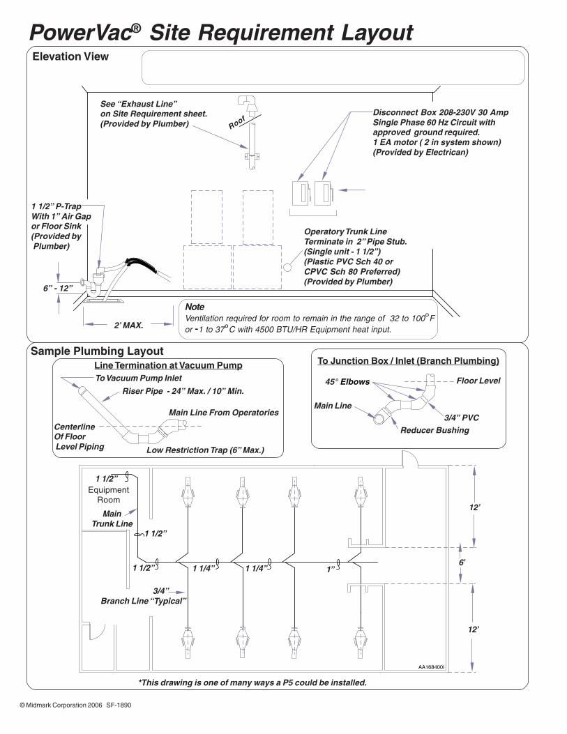
PowerVac® Site Requirement Layout
See “Exhaust Line”on Site Requirement sheet.(Provided by Plumber)
Disconnect Box 208-230V 30 AmpSingle Phase 60 Hz Circuit withapproved ground required.1 EA motor ( 2 in system shown)(Provided by Electrican)
6” - 12”
2’ MAX.
1 1/2” P-TrapWith 1” Air Gapor Floor Sink(Provided by Plumber)
Operatory Trunk LineTerminate in 2” Pipe Stub.(Single unit - 1 1/2”)(Plastic PVC Sch 40 orCPVC Sch 80 Preferred)(Provided by Plumber)
Elevation View
Sample Plumbing Layout
3/4”Branch Line “Typical”
EquipmentRoom
1”1 1/4”1 1/4”1 1/2”
1 1/2”
1 1/2”
Roof
NoteVentilation required for room to remain in the range of 32 to 100°For -1 to 37°C with 4500 BTU/HR Equipment heat input.
Line Termination at Vacuum PumpTo Vacuum Pump Inlet
Riser Pipe - 24” Max. / 10” Min.
Main Line From Operatories
Low Restriction Trap (6” Max.)
CenterlineOf Floor Level Piping
To Junction Box / Inlet (Branch Plumbing)
Floor Level
3/4” PVCReducer Bushing
Main Line
45° Elbows
MainTrunk Line
12’
12’
6’
*This drawing is one of many ways a P5 could be installed.

© Midmark Corporation 2007 1
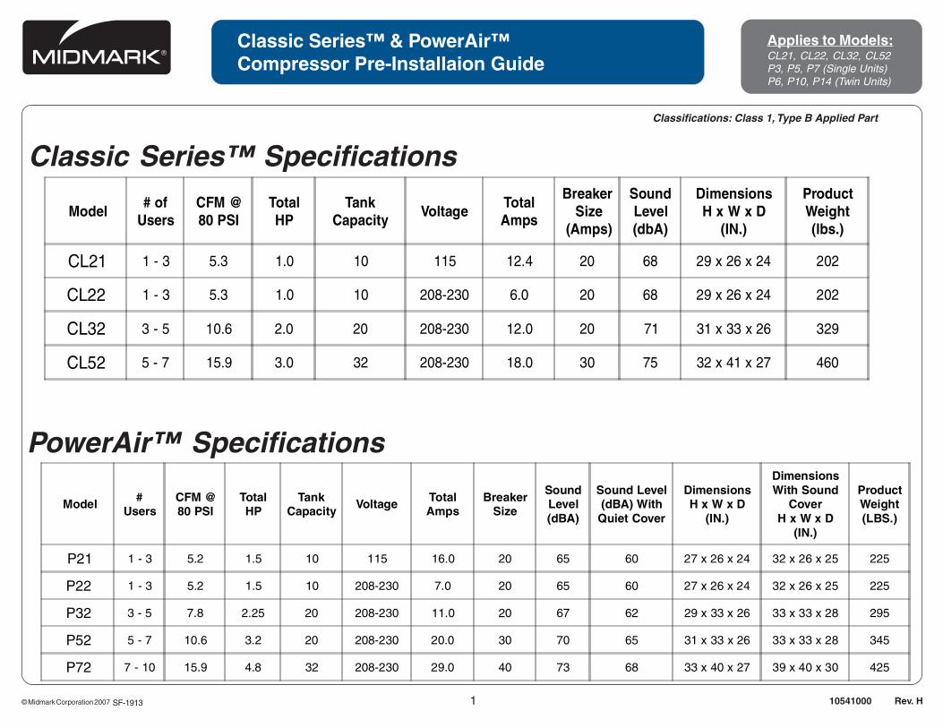
Classic Series™ & PowerAir™Compressor Pre-Installaion Guide
Applies to Models:CL21, CL22, CL32, CL52P3, P5, P7 (Single Units)P6, P10, P14 (Twin Units)
10541000 Rev. H
Classifications: Class 1, Type B Applied Part
Classic Series™ Specifications
PowerAir™ Specifications
SF-1913
Model# of
UsersCFM @80 PSI
TotalHP
TankCapacity
VoltageTotalAmps
Breaker Size
(Amps)
SoundLevel(dbA)
DimensionsH x W x D
(IN.)
ProductWeight(lbs.)
CL21 1 - 3 5.3 1.0 10 115 12.4 20 68 29 x 26 x 24 202
CL22 1 - 3 5.3 1.0 10 208-230 6.0 20 68 29 x 26 x 24 202
CL32 3 - 5 10.6 2.0 20 208-230 12.0 20 71 31 x 33 x 26 329
CL52 5 - 7 15.9 3.0 32 208-230 18.0 30 75 32 x 41 x 27 460
Model #Users
CFM @80 PSI
TotalHP
TankCapacity
Voltage TotalAmps
BreakerSize
SoundLevel(dBA)
Sound Level(dBA) With
Quiet Cover
DimensionsH x W x D
(IN.)
DimensionsWith Sound
CoverH x W x D
(IN.)
ProductWeight(LBS.)
P21 1 - 3 5.2 1.5 10 115 16.0 20 65 60 27 x 26 x 24 32 x 26 x 25 225
P22 1 - 3 5.2 1.5 10 208-230 7.0 20 65 60 27 x 26 x 24 32 x 26 x 25 225
P32 3 - 5 7.8 2.25 20 208-230 11.0 20 67 62 29 x 33 x 26 33 x 33 x 28 295
P52 5 - 7 10.6 3.2 20 208-230 20.0 30 70 65 31 x 33 x 26 33 x 33 x 28 345
P72 7 - 10 15.9 4.8 32 208-230 29.0 40 73 68 33 x 40 x 27 39 x 40 x 30 425

AA189300
© Midmark Corporation 2007
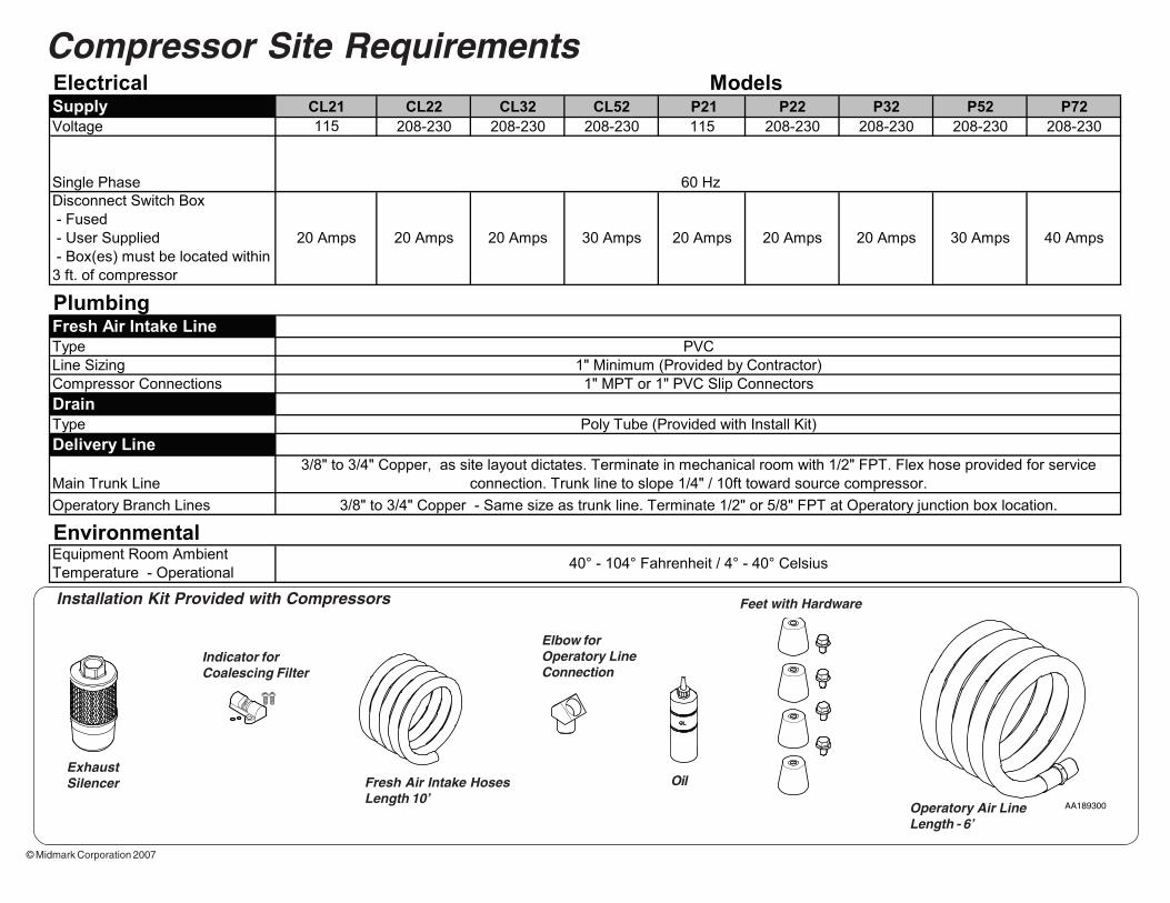
Compressor Site Requirements
Fresh Air Intake HosesLength 10’
ExhaustSilencer
Feet with HardwareInstallation Kit Provided with Compressors
Operatory Air LineLength - 6’
Elbow forOperatory LineConnection
Indicator forCoalescing Filter
Oil
Supply CL21 CL22 CL32 CL52 P21 P22 P32 P52 P72
Voltage 115 208-230 208-230 208-230 115 208-230 208-230 208-230 208-230
Single Phase
Disconnect Switch Box
- Fused
- User Supplied
- Box(es) must be located within
3 ft. of compressor
Fresh Air Intake Line
Type
Line Sizing
Compressor Connections
Drain
Type
Delivery Line
Main Trunk Line
Operatory Branch Lines
Equipment Room Ambient
Temperature - Operational
PVC
Poly Tube (Provided with Install Kit)
1" Minimum (Provided by Contractor)
1" MPT or 1" PVC Slip Connectors
Plumbing
30 Amps
60 Hz
40° - 104° Fahrenheit / 4° - 40° Celsius
3/8" to 3/4" Copper - Same size as trunk line. Terminate 1/2" or 5/8" FPT at Operatory junction box location.
3/8" to 3/4" Copper, as site layout dictates. Terminate in mechanical room with 1/2" FPT. Flex hose provided for service
connection. Trunk line to slope 1/4" / 10ft toward source compressor.
Environmental
40 Amps
Electrical Models
20 Amps 20 Amps 20 Amps 30 Amps 20 Amps 20 Amps 20 Amps

© Midmark Corporation 2007
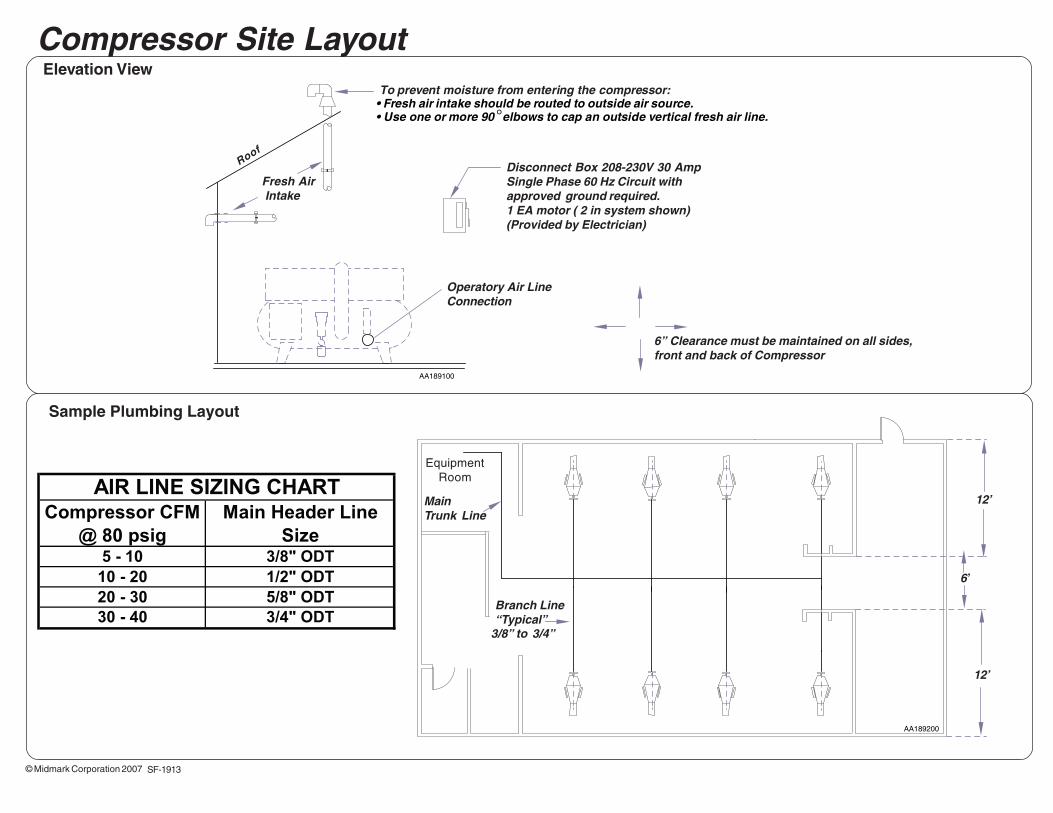
Compressor CFM
@ 80 psig
Main Header Line
Size5 - 10 3/8" ODT
10 - 20 1/2" ODT
20 - 30 5/8" ODT
30 - 40 3/4" ODT
AIR LINE SIZING CHART
AA189100
AA189200
Specification Sheet Compressor Site Layout
Disconnect Box 208-230V 30 AmpSingle Phase 60 Hz Circuit withapproved ground required.1 EA motor ( 2 in system shown)(Provided by Electrician)
Operatory Air LineConnection
Elevation View
Roof
Fresh Air Intake
To prevent moisture from entering the compressor:• Fresh air intake should be routed to outside air source.• Use one or more 90 °elbows to cap an outside vertical fresh air line.
Sample Plumbing Layout
MainTrunk Line
EquipmentRoom
Branch Line“Typical”
3/8” to 3/4”
12’
12’
6’
6” Clearance must be maintained on all sides,front and back of Compressor
SF-1913
© Midmark Corporation 2007 1
Classic Series™ & PowerAir™Compressor Pre-Installaion Guide
Applies to Models:CL21, CL22, CL32, CL52P3, P5, P7 (Single Units)P6, P10, P14 (Twin Units)
10541000 Rev. H
Classifications: Class 1, Type B Applied Part
Classic Series™ Specifications
PowerAir™ Specifications
SF-1913
Model# of
UsersCFM @80 PSI
TotalHP
TankCapacity
VoltageTotalAmps
Breaker Size
(Amps)
SoundLevel(dbA)
DimensionsH x W x D
(IN.)
ProductWeight(lbs.)
CL21 1 - 3 5.3 1.0 10 115 12.4 20 68 29 x 26 x 24 202
CL22 1 - 3 5.3 1.0 10 208-230 6.0 20 68 29 x 26 x 24 202
CL32 3 - 5 10.6 2.0 20 208-230 12.0 20 71 31 x 33 x 26 329
CL52 5 - 7 15.9 3.0 32 208-230 18.0 30 75 32 x 41 x 27 460
Model #Users
CFM @80 PSI
TotalHP
TankCapacity
Voltage TotalAmps
BreakerSize
SoundLevel(dBA)
Sound Level(dBA) With
Quiet Cover
DimensionsH x W x D
(IN.)
DimensionsWith Sound
CoverH x W x D
(IN.)
ProductWeight(LBS.)
P21 1 - 3 5.2 1.5 10 115 16.0 20 65 60 27 x 26 x 24 32 x 26 x 25 225
P22 1 - 3 5.2 1.5 10 208-230 7.0 20 65 60 27 x 26 x 24 32 x 26 x 25 225
P32 3 - 5 7.8 2.25 20 208-230 11.0 20 67 62 29 x 33 x 26 33 x 33 x 28 295
P52 5 - 7 10.6 3.2 20 208-230 20.0 30 70 65 31 x 33 x 26 33 x 33 x 28 345
P72 7 - 10 15.9 4.8 32 208-230 29.0 40 73 68 33 x 40 x 27 39 x 40 x 30 425
AA189300
© Midmark Corporation 2007
Compressor Site Requirements
Fresh Air Intake HosesLength 10’
ExhaustSilencer
Feet with HardwareInstallation Kit Provided with Compressors
Operatory Air LineLength - 6’
Elbow forOperatory LineConnection
Indicator forCoalescing Filter
Oil
Supply CL21 CL22 CL32 CL52 P21 P22 P32 P52 P72
Voltage 115 208-230 208-230 208-230 115 208-230 208-230 208-230 208-230
Single Phase
Disconnect Switch Box
- Fused
- User Supplied
- Box(es) must be located within
3 ft. of compressor
Fresh Air Intake Line
Type
Line Sizing
Compressor Connections
Drain
Type
Delivery Line
Main Trunk Line
Operatory Branch Lines
Equipment Room Ambient
Temperature - Operational
PVC
Poly Tube (Provided with Install Kit)
1" Minimum (Provided by Contractor)
1" MPT or 1" PVC Slip Connectors
Plumbing
30 Amps
60 Hz
40° - 104° Fahrenheit / 4° - 40° Celsius
3/8" to 3/4" Copper - Same size as trunk line. Terminate 1/2" or 5/8" FPT at Operatory junction box location.
3/8" to 3/4" Copper, as site layout dictates. Terminate in mechanical room with 1/2" FPT. Flex hose provided for service
connection. Trunk line to slope 1/4" / 10ft toward source compressor.
Environmental
40 Amps
Electrical Models
20 Amps 20 Amps 20 Amps 30 Amps 20 Amps 20 Amps 20 Amps
© Midmark Corporation 2007
Compressor CFM
@ 80 psig
Main Header Line
Size5 - 10 3/8" ODT
10 - 20 1/2" ODT
20 - 30 5/8" ODT
30 - 40 3/4" ODT
AIR LINE SIZING CHART
AA189100
AA189200
Specification Sheet Compressor Site Layout
Disconnect Box 208-230V 30 AmpSingle Phase 60 Hz Circuit withapproved ground required.1 EA motor ( 2 in system shown)(Provided by Electrician)
Operatory Air LineConnection
Elevation View
Roof
Fresh Air Intake
To prevent moisture from entering the compressor:• Fresh air intake should be routed to outside air source.• Use one or more 90 °elbows to cap an outside vertical fresh air line.
Sample Plumbing Layout
MainTrunk Line
EquipmentRoom
Branch Line“Typical”
3/8” to 3/4”
12’
12’
6’
6” Clearance must be maintained on all sides,front and back of Compressor
SF-1913
© Midmark Corporation 2007 1
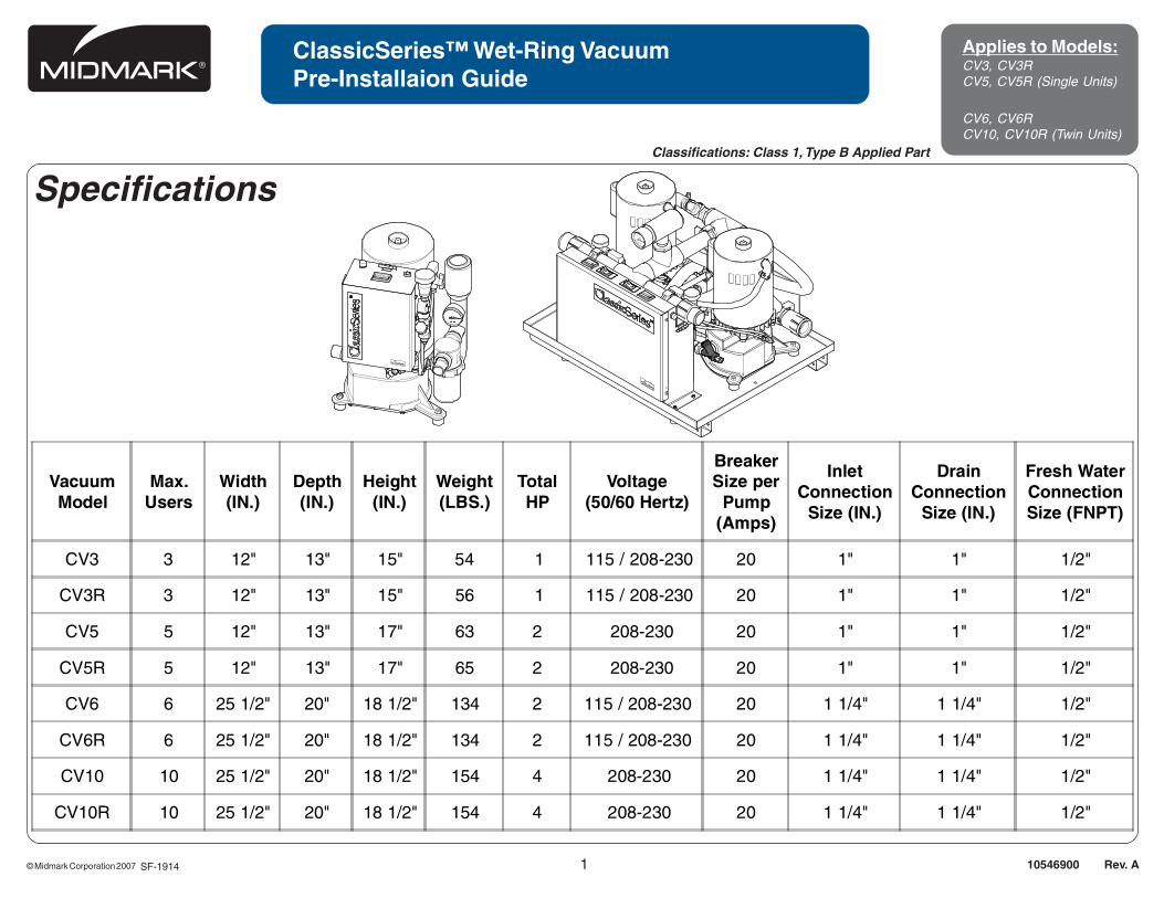
ClassicSeries™ Wet-Ring VacuumPre-Installaion Guide
Applies to Models:CV3, CV3RCV5, CV5R (Single Units)
CV6, CV6RCV10, CV10R (Twin Units)
10546900 Rev. A
Specifications
SF-1914
Classifications: Class 1, Type B Applied Part
VacuumModel
Max.Users
Width(IN.)
Depth(IN.)
Height(IN.)
Weight(LBS.)
TotalHP
Voltage(50/60 Hertz)
BreakerSize per
Pump(Amps)
InletConnection
Size (IN.)
DrainConnection
Size (IN.)
Fresh WaterConnectionSize (FNPT)
CV3 3 12" 13" 15" 54 1 115 / 208-230 20 1" 1" 1/2"
CV3R 3 12" 13" 15" 56 1 115 / 208-230 20 1" 1" 1/2"
CV5 5 12" 13" 17" 63 2 208-230 20 1" 1" 1/2"
CV5R 5 12" 13" 17" 65 2 208-230 20 1" 1" 1/2"
CV6 6 25 1/2" 20" 18 1/2" 134 2 115 / 208-230 20 1 1/4" 1 1/4" 1/2"
CV6R 6 25 1/2" 20" 18 1/2" 134 2 115 / 208-230 20 1 1/4" 1 1/4" 1/2"
CV10 10 25 1/2" 20" 18 1/2" 154 4 208-230 20 1 1/4" 1 1/4" 1/2"
CV10R 10 25 1/2" 20" 18 1/2" 154 4 208-230 20 1 1/4" 1 1/4" 1/2"
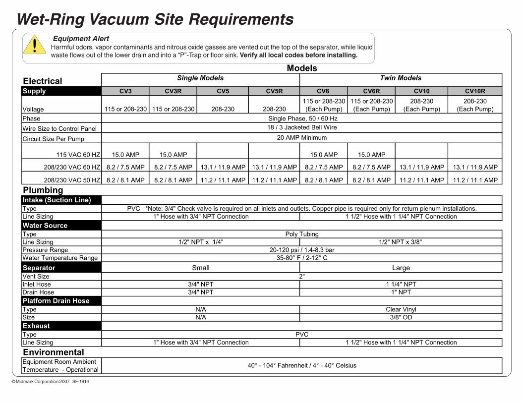
ElectricalSupply CV3 CV3R CV5 CV5R CV6 CV6R CV10 CV10R
Voltage 115 or 208-230 115 or 208-230 208-230 208-230
115 or 208-230
(Each Pump)
115 or 208-230
(Each Pump)
208-230
(Each Pump)
208-230
(Each Pump)
Phase
Wire Size to Control Panel
Circuit Size Per Pump
115 VAC 60 HZ 15.0 AMP 15.0 AMP 15.0 AMP 15.0 AMP
208/230 VAC 60 HZ 8.2 / 7.5 AMP 8.2 / 7.5 AMP 13.1 / 11.9 AMP 13.1 / 11.9 AMP 8.2 / 7.5 AMP 8.2 / 7.5 AMP 13.1 / 11.9 AMP 13.1 / 11.9 AMP
208/230 VAC 50 HZ 8.2 / 8.1 AMP 8.2 / 8.1 AMP 11.2 / 11.1 AMP 11.2 / 11.1 AMP 8.2 / 8.1 AMP 8.2 / 8.1 AMP 11.2 / 11.1 AMP 11.2 / 11.1 AMP
Intake (Suction Line)
Type
Line Sizing
Water Source
Type
Line Sizing
Pressure Range
Water Temperature Range
Separator
Vent Size
Inlet Hose
Drain Hose
Platform Drain Hose
Type
Size
Exhaust
Type
Line Sizing
Equipment Room Ambient
Temperature - Operational
Clear Vinyl
3/8" OD
N/A
N/A
1" NPT
Models
1 1/2" Hose with 1 1/4" NPT Connection
35-80° F / 2-12° C
20-120 psi / 1.4-8.3 bar
Single Models Twin Models
Plumbing
18 / 3 Jacketed Bell Wire
Single Phase, 50 / 60 Hz
40° - 104° Fahrenheit / 4° - 40° Celsius
2"
Environmental
Small Large
3/4" NPT 1 1/4" NPT
3/4" NPT
PVC
1" Hose with 3/4" NPT Connection
20 AMP Minimum
1/2" NPT x 1/4" 1/2" NPT x 3/8"
Poly Tubing
1" Hose with 3/4" NPT Connection 1 1/2" Hose with 1 1/4" NPT Connection
PVC *Note: 3/4" Check valve is required on all inlets and outlets. Copper pipe is required only for return plenum installations.
© Midmark Corporation 2007 SF-1914
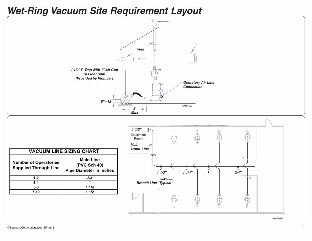
Wet-Ring Vacuum Site Requirements Equipment Alert
Harmful odors, vapor contaminants and nitrous oxide gasses are vented out the top of the separator, while liquid waste flows out of the lower drain and into a “P”-Trap or floor sink. Verify all local codes before installing.
© Midmark Corporation 2007 SF-1914
Specification Sheet
AA188601
Specification SheetLubricated Compressors
Wet-Ring Vacuum Site Requirement Layout
MainTrunk Line
Branch Line “Typical”3/4”
1 1/2” 1 1/4” 1” 3/4”
1 1/2”Equipment
Room
AA188500
Operatory Air LineConnection
Vent
2’Max
1 1/2” P-Trap With 1” Air Gapor Floor Sink
(Provided by Plumber)
6” - 12”
VACUUM LINE SIZING CHART
Number of Operatories
Supplied Through Line
Main Line
(PVC Sch 40)
Pipe Diameter in Inches
1-2 3/4
3-4 1
5-6 1 1/4
7-10 1 1/2

© Midmark Corporation 2007 1
PowerMax Surgical Suction SystemPre-Installaion Guide
Applies to Models:PM-1PM-3PM-4
10559300 Rev. A
Specifications
AA206100
www.Midmark.com • 1-800-Midmark • www.Documark.com
Model Users Height(IN.)
Width(IN.)
Depth(IN.)
Weight(LBS.)
HP Voltage(50/60 Hertz)
BreakerSize per
Pump(Amps)
TankCapacity
(GAL)
CFMMaximum
PM-1 1 31" 32" 25" 150 3/4 208-230 @ 5.1 Amp 20 20 8
PM-3 2-3 31" 32" 25" 210 1.5 208-230 @ 9.7 Amp 20 20 16
PM-4 3-4 34" 38" 27" 290 2.25 208-230 @ 14.3 Amp 20 32 24
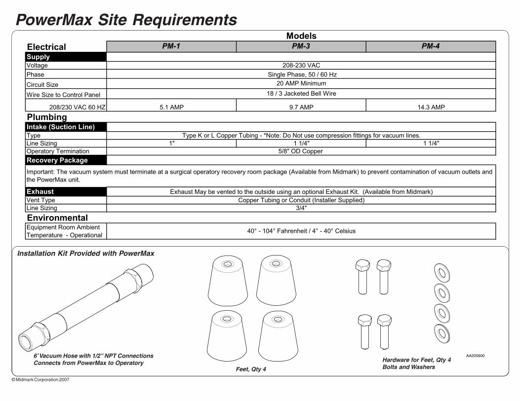
© Midmark Corporation 2007
ElectricalSupply
Voltage
Phase
Circuit Size
Wire Size to Control Panel
208/230 VAC 60 HZ
Intake (Suction Line)
Type
Line Sizing
Operatory Termination
Recovery Package
Exhaust
Vent Type
Line Sizing
Equipment Room Ambient
Temperature - Operational
9.7 AMP 14.3 AMP
Type K or L Copper Tubing - *Note: Do Not use compression fittings for vacuum lines.
1" 1 1/4" 1 1/4"
Exhaust May be vented to the outside using an optional Exhaust Kit. (Available from Midmark)
5/8" OD Copper
40° - 104° Fahrenheit / 4° - 40° Celsius
Environmental
Copper Tubing or Conduit (Installer Supplied)
Important: The vacuum system must terminate at a surgical operatory recovery room package (Available from Midmark) to prevent contamination of vacuum outlets and
the PowerMax unit.
3/4"
Models
Plumbing
18 / 3 Jacketed Bell Wire
Single Phase, 50 / 60 Hz
20 AMP Minimum
208-230 VAC
PM-1 PM-3 PM-4
5.1 AMP
PowerMax Site Requirements
AA205600
Feet, Qty 4
Installation Kit Provided with PowerMax
Hardware for Feet, Qty 4Bolts and Washers
6’ Vacuum Hose with 1/2” NPT ConnectionsConnects from PowerMax to Operatory
© Midmark Corporation 2007
AA206500
AA206600
Specification SheetLubricated Compressors
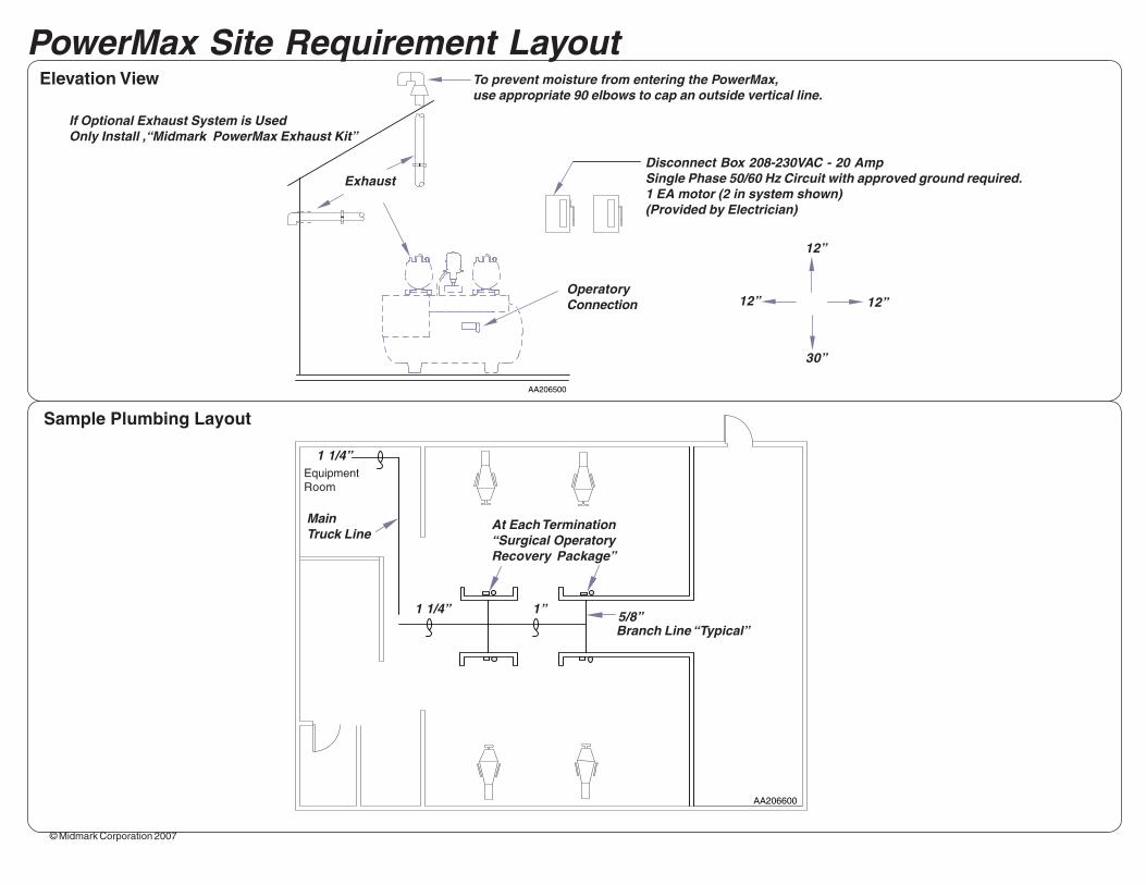
PowerMax Site Requirement Layout
Disconnect Box 208-230VAC - 20 AmpSingle Phase 50/60 Hz Circuit with approved ground required.1 EA motor (2 in system shown)(Provided by Electrician)
If Optional Exhaust System is UsedOnly Install ,“Midmark PowerMax Exhaust Kit”
Exhaust
To prevent moisture from entering the PowerMax,use appropriate 90 elbows to cap an outside vertical line.
EquipmentRoom
MainTruck Line
5/8”Branch Line “Typical”
1 1/4”
1 1/4” 1”
Elevation View
Sample Plumbing Layout
At Each Termination“Surgical OperatoryRecovery Package”
OperatoryConnection 12” 12”
12”
30”