
Laser Welding Techniques for Alloy 718Due to its inherently small heat affected zone, laser welding...
16
LASER WELDING TECHNIQUES FOR ALLOY 718 Mary H. McCay, T. Dwayne McCay, C. Michael Sharp, and Narendra B. Dahotre Center for Laser Applications The University of Tennessee Space Institute Tullahoma, Tennessee 37388 Abstract Results from a program to study laser welding of Inconel 718 arc discussed. This includes microstructural studies of welded wrought, wrought grain grown and cast material. Samples were laser processed using both CW and pulse tailoring. The heat affected zones and precipitate regions were determined and the influence of sidejet pressure and orientation on weld shape was established. Superalloys 718,625 and Various Derivatives Edited by Edward A. Loria The Minerals, Metals & Materials Society, 1991 719
Transcript of Laser Welding Techniques for Alloy 718Due to its inherently small heat affected zone, laser welding...

LASER WELDING TECHNIQUES FOR ALLOY 718
Mary H. McCay, T. Dwayne McCay, C. Michael Sharp, and Narendra B. Dahotre
Center for Laser Applications
The University of Tennessee Space Institute
Tullahoma, Tennessee 37388
Abstract
Results from a program to study laser welding of Inconel 718 arc discussed. This
includes microstructural studies of welded wrought, wrought grain grown and cast
material. Samples were laser processed using both CW and pulse tailoring. The heat affected zones and precipitate regions were determined and the influence of sidejet pressure and orientation on weld shape was established.
Superalloys 718,625 and Various Derivatives Edited by Edward A. Loria
The Minerals, Metals & Materials Society, 1991
719

Introduction
Inconel 718 accounts for a significant portion of all superalloy production and usage
and improved fabrication techniques for the alloy are of significant interest. Welding
is one of the more desirable techniques and has been seriously investigated for turbine
and aircraft engine components with the predominant concerns being microfissuring,
cracking, and reduction of properties within the heat affected zone (HAZ). Recently,
laser welding has been considered since it uses a very localized heat source which produces a narrow HAZ. The purpose of this paper is to present the results of an
on-going program which investigates the various aspects of CW (Continuous Wave) and pulsed laser welding and their effects on the weld character and HAZ of three microstructures of Inconel: wrought, wrought-grain grown and cast.
Background
The composition and phases of Alloy 718 have been thoroughly discussed in this and earlier volumes’ and therefore will not be repeated here. Studies of laser welding of Alloy 718 are, however, fairly recent and will be briefly reviewed.
When Inconel718 welds are metallurgically evaluated, they often reveal microfissures in the heat affected zone. These occur primarily under the nailhead, a fusion zone shape which is typical of many different welding processes. The microfissures are thought to be due to the combination of liquation and the significant stresses which occur during
cooling. They create problems in hardware fabrication and repair and, therefore, the
welding of Inconel 718 continues to be a challenge to the researcher and manufacturer.
Due to its inherently small heat affected zone, laser welding offers potential promise
for producing crackfree Inconel 718 joints. A study2 on the welding and cutting of 718 with a 15kW CW CO2 laser indicated that it could be an effective joining method for up to one half inch thicknesses. A definite nailhead was produced, however, which
contained isolated instances of microfissuring and some porosity. Studies of pulse laser welding on Inconel 718 have also been conducted using Neodymium-YAG lasers.3z4 In these instances, the material cracked at the nailhead in both individual and overlapping
welds. The cracks were intergranular and attributed to solidification cracking. A more recent study5 used pulsed CO;! laser welding reduced the nailhead size and also reduced
the associated microfissuring.
Eliminating the nailhead by altering the shape of the weld fusion zone through plasma
control has been suggested 7$tg by studies in which investigators optimized the assist gas parameters during CW CO2 1 aser welding of 304 stainless steel. The following gas parameters were varied: gas species, gas pressure, nozzle angle, nozzle diameter,
nozzle height and gas-workpiece interaction position. A set of gas conditions was found at which the profile of the weld transitioned from the characteristic wine glass to a straight sided shape. It was proposed9 that the assist gas suppressed the plasma at pressures slightly higher than the pressure of the metallic vapor by forcing the vapor
to flow away from the focussed laser beam along the rear wall of the cavity. This minimized the plasma absorption loss. The resultant weld had greater penetration, though with uneven depth and some root porosity.
720

These studies indicate that while laser welding has many of the same inherent problems
as other welding techniques, e.g. nailhead cracking, it does offer the possibility of
minimizing these problems. Through appropriate control of the heat source with pulse
tailoring and plasma location manipulation, the weld shape and thermal history can
be varied. The purpose of the investigation being discussed herein is to determine how
that variation in weld characteristics relates to the heat source, and if it can result in better Alloy 718 welds.
Procedure
Laser Processing System
The laser used for the experiments was a Rofin-Sinar RS3000 fast axial flow CO2 laser with a peak power of 3,700 watts and configured to a TEMra mode with a beam
divergence of less than 2 milliradians. The laser output can be either continuous wave (CW) or pulsed. The b earn is focussed onto the workpiece with an off-axis parabolic mirror having a focal length of 150 mm. The beam is directed perpendicular to the workpiece through a nozzle which delivers a coaxial and a sidejet flow of inert gas. A
specially designed nozzle was usedrr when variations in the sidejet flow orientation wa.s
desired.
Power delivered to the workpiece was measured using a Scientech calorimeter. The
workpiece was translated horizontally beneath the beam at a constant speed using an
Aerotech x-y table and CNC controller. Restrained welds were made using a fixture designed to produce both horizontal and vertical pressure on the materia1.i’ Five weld processing series were run using various selected processing parameters. The series and
the parameters are listed in Table I.
Various analytical techniques were applied during the processing. These include”-” plasma spectroscopy, video, photodiode, and high speed camera. The radiation cmitt,ed by the plasma formed above the material during laser processing was obtained”’ using
a l/4 wave spectrometer over a spectral range of 2500-5000 Angstroms. Five separate
windows were examined. One hundred temporal scans were averaged using an optical
multichannel analyzer. The emission spectrum with the identified elements is shown in Figure 1.
Preliminary Allov Characterization
To distinguish differences in homogeneity, Differential Scanning Calorimetry (DSC)
was applied to wrought (grain size #S), wrought grain grown (gra.in size #4) and
cast material. The DSC tests were conducted at the High Tempera.ture Materials
Laboratory in Oak Ridge National Laboratory. The 150-160 mg samples were processed
in argon at two heating and cooling rates. Temperatures at which transformations occurred were identified and are presented in Table II for the 40”C/min heating and
cooling rate.
Analytical Model
An analytical model13 was modified to determine the temperature field around the weld. It is based upon superposed solutions for a moving point and line heat source“’
721

Table I Processing Parameters for Inconel 7 3 Laser Welds
3200
A
+---H 2475
Bl t
2900
1900
B2 t
2600
2250
B3
C
2000
D
2.5 45 0.3175
t 77
I.2
t "i"
0.3175
2.5 a5
I.2 37 0.3175
t 80
1.2 37 0.3175
t 100
1.2 52.2 0.3175
t 100
2.5 100 0.3175
He 60
He 26
He 26
He 26
N2 He Ar
52.2
o-, 9.2 Od24.8 o-, 7.8
;
-1 -1 U U
He He 45 45 20 20 -3 -3 U U
He He 45 45 20 20 -3 -3 R R
He He 45 45 20 20 -3 -3 R R
R R
k k 35 35 O-+24.3 O-+24.3 -2.5 -2.5 U U He He 42 42 O-64.2 O-64.2 Ar Ar 45 45 o-+19.5 o-+19.5
65 65
CG-2147

Table II Transformation Temperatures in IN 718
Sample DSC Treatment Transformation Temperatures (“C)
Grain
Grown
Cast Heating 40”C/min 585, 770,
Wrought Heating 40°C/min 655, 850, 1220
1130,
Wrought Heating 40”C/min 615, 760, 912, 1025, 1220, 1275
1180, 1205, 1280
OJ 2500. 3000. 3500. 4000. 1500. 5000. 5500.
lrarelrnglll (A)
04 / .4000. 4100. 4200. ‘4300. ,440o. 4500
\iwclcngth (A\)
3700. 3000.
Ma\-elenglh (A)
Figure 1 - The emission spectrum of Inconel 718 in helium shield gas for (a) the spectral range of 2500 to 5000 A”, (b) th e spectra,1 range of 3500 to 4000 A”, and (c) the spectral range of 4000 to 4500 A”.
723

Distance (cm)
(4 (b)
.::.... . . . . . . .._.................... ..,... :::::::j,::::~.:jjjj::::ji::::jij::~,: :.:.:.:.:.:_:.~:.:.:.:.:.:.:.:.~~~~~:
:::::::::::::i::::::::::::::::::::::::::::~ . . . . . . . . . .._... . . . . . . . . .._.. . . . .._.. . . . . . . . .._......._...... . . . . .._.. . . .._......... :::::::::::::::::::::::::::::::::::: :.:.:.:.:.:.:.~:::::::~:;:;:;:~:;:~:;:~:;:
(cl CG-2144
Figure 2 - Predicted locations of DSC (heating) transformations adjacent to the fusion zone in (a) Wrought (b) Wrought Grain Grown and (c) Cast Inconel 718.
TOP TOP 0.30 -
2.25 2.50 2.75
Gradient (‘c/cm x 1 04)
Figure 3 - Temperature gradient in the HAZ as a function of weld depth.
724
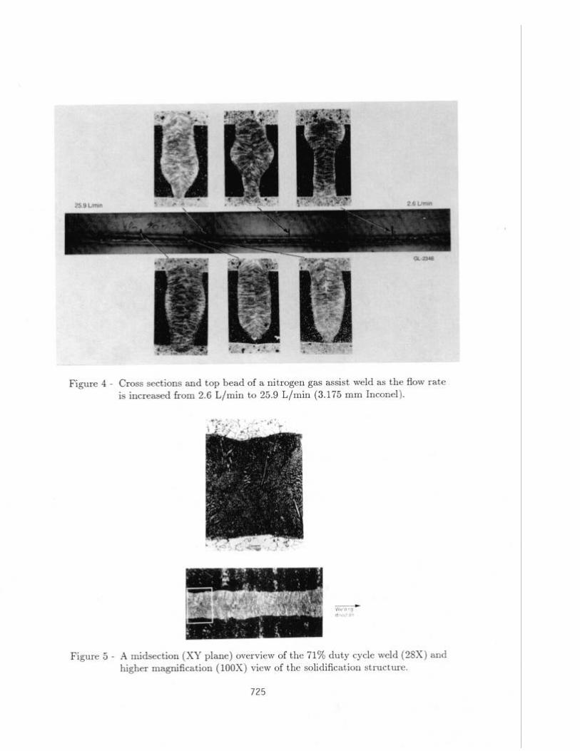
Figure 4 - Cross sections and top bead of a nitrogen gas assist weld as the flow rate is increased from 2.6 L/ min to 25.9 L/min (3.175 mm Inconel).
Figure 5 - A midsection (XY plane) overview of the 71% duty cycle weld (28X) and higher magnification (100X) view of the solidification structure.
725

+ Welding Direction
Figure 6 - A midsection (XY plane) overview of the 45% duty cycle weld (28X) and
higher magnification (100X) views of the solidification and pore structure.
726

“V - :.
(b) 100% Duty Cycle Welds
w 52% Duty Cycle Vc Telds
-1
(4
Figure 7 - Slant grind sections of (a) Wrought, (b) Wrought Grain Grown, and (c) Cast Inconel 718.
727

t Fusion Zone G-- Fusion Zone CG-2115
Wrought
Wrought Grain Grown
CAST
Figure 8 - Vickers microhardness values in the region adjacent to the fusion zone at the top (A) and base (B) of the nailhead, distances in cm.
728

0.000 0.050 0.100 0.150 0.200 0.250
Width (cm)
(a)
0.000 0.050 0.100 0.150
Width (cm) 0.200 0.250
0.000 0.050 0.100 0.150 0.200 0.250
Width (cm)
Cc)
CG-2113
Figure 9 - The HAZ and precipitation regions adjacent to CW welds in (a) Wrought, (b) Wrought Grain Grown, and (c) Cast Inconel 718.
729

100% Duty Cycle
52% Duty Cycle
Oislance from Weld Cenleiline (cm)
(W !xtance hrn Weld Cenlerll”? (Cm)
CG-2 146
Figure 10 - Slant grind sections of 100% and 52% duty cycle welds in (a) Wrought, (b) Wrought Grain Grown,
and (c) Cast Material, showing precipitation and microhardness regions.

and predicts microfissuring. The modification to the model uses the experimentally de-
termined top bead width, nailhead depth, and minimum weld width to calculate the line
source power and point source power and location that will reproduce the weld shape
(as represented by the 1336°C isotherm). Transition region distances and temperature
gradients in the HAZ can then be calculated for the particular weld configuration. The predicted location of the heating transitions as determined by DSC analysis are shown in Figure 2. Figure 3 illustrates the variation with depth of the temperature gradients
present in the CW welds for samples in Series B3.
Metallographic Results
Weld structures were examined in sections perpendicular to the weld direction, parallel
to the weld direction and sample surface, and at a 15” angle with respect to the weld
direction. The latter two examinations were necessitated by the three-dimensionality
produced by pulsed welding. The technique which used the angled cross-section was
developed to circumvent the numerous sections that had to be examined when using the second technique. Samples were mounted, ground and polished prior to etching
with waterless Icallings reagent. Figure 4 shows perpendicular sections from Series D, Figures 5 and 6 show parallel sections from Series A, and Figure 7 shows slant
grind sections from Series B3. Any occurrence of centerline cracks, microfissures, and porosity was noted in all samples.
Microhardness measurements were made perpendicular to the fusion zone at increments
along the depth of the weld. Typical results for the Series B3 CW welds in the regions A (top) and C (base of the nailhead) are shown in Figure 8. The distance at which the measurements reached the untreated matrix value was considered to be the end of the HAZ. The width of the region over which obvious grain boundary melting and
precipitation occurred was measured for the Series B3 welds in both the perpendicular
and slant grind sections. Figures 9 and 10 show the extent of the HAZ and precipitate regions in the Series B3 materials for CW and pulsed welds in both the perpendicular and slant grind orientations. The location of any microfissures that occurred is noted on the figures.
Fusion zone curvature was determined for the welds in Series B2, B3 and D. (Curvature is defined as the length of the fusion zone divided by the straight line distance.) A plot of curvature as a function of duty cycle for the Series B3 welds is shown in Figure 11.
R.esults and Discussion
The three types of Inconel vary significantly in both the number and the location of
the transformations which will occur during welding (Figure 2). The wrought grain
grown (the most homogenized) material exhibits the fewest transformations. The cast and wrought are similar to each other. They each should exhibit lower temperature
eutectic melting as a result of their inhomogeneous structures. This occurs up to 0.02 cm from the fusion zone.
731
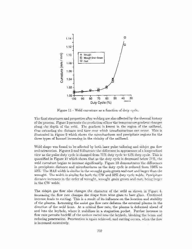
100 90 80 70 60 50 40 30
Duty Cycle (%) CG-2114
Figure 11 - Weld curvature as a function of duty cycle.
The final structures and properties after welding are also affected by the thermal history
of the process. Figure 3 presents the prediction of how the temperature gradient changes along the depth of the weld. The gradient is lowest in the region of the nailhead,
thus extending the distance and time over which transformations can occur. This is illustrated in Figure 9 which shows the microhardness and precipitate regions for the three types of Inconel increasing in the vicinity of the nailhead.
Weld shape was found to be affected by both laser pulse tailoring and sidejet gas flow and orientation. Figures 5 and 6 illustra.te the difference in appearance of a longitudinal
view as the pulse duty cycle is changed from 71% duty cycle to 45% duty cycle. This is
quantified in Figure 11 which shows that as the duty cycle is decreased below 71%, the
weld curvature begins to increase significantly. Figure 10 demonstrates the differences in precipitate distance and microhardness as the duty cycle is reduced from 100% to 52%. The HA2 width is similar in the wrought grain grown and cast and larger than the wrought. The width is similar for both the CW and 52% duty cycle welds. Precipitate distance increases in the order of wrought, wrought grain grown and cast, being larger in the CW welds.
The sidejet gas flow also changes the character of the weld as shown in Figure 4. Increasing the flow rate changes the shape from wine glass to beer glass. Continued increase leads to cutting. This is a result of its influence on the location and stability of the plasma. Increasing the assist gas flow rate deforms the external plasma in the direction of the weld front. At a critical flow rate, the plasma is deformed ahead of
and into the keyhole, where it stabilizes in a stagnation pocket. Further increase in flow rate permits backfill of the molten metal into the keyhole, blocking the beam and
reducing penetration. Penetration is again achieved, and cutting occurs, when the flow is increased excessively.
732
As shown in Figure 1, the radiating constituents within the plasma are identified as
nickel, iron, chromium and niobium. The plasma is comprised primarily of neutral
atoms, singly ionized metal atoms and electrons from these elements.
Acknowledgments
The authors would like to acknowledge the contributions of the Marshall Space Flight Center, Materials and Processes Laboratory and in particular Mr. R. J. Schwing- hamer and Mr. Ernie Bayless for providing the wrought Inconel, and Dr. A. Nunes for discussions on his microfissuring model. The Oak Ridge High Temperature Mate- rials Laboratory and Dr. C. R. Hubbard allowed access to their Differential Scanning
Calorimeter. In particular the authors would like to thank the Center for Advanced
Space Propulsion for their sponsorship of a portion of this work under NASA Grant
No. NAGW-1195. The authors are also indebted to Mr. Kevin Zysk and Mr. Michael
Womack who performed portions of this project as part of their Masters’ programs.
References
1. E. A. Loria, ed., Superalloy 718, Metallurgy and Application (Warrendale, PA: TMS Publication 1989).
2. C. M. Banas, Final Report, Contract NAS8-36306, 1988.
3. L. A. Weeter, C. E. Albright and W. H. Jones, Welding Research Supplement, Masch
1986, 51s-62s.
4. J. P. R.eynolds, H. W. Kerr, P. J. Fehrenback, L. Bourque, and R. D. Davidson, Advances in Welding Science and Technology, TWR “86, Proceedings of an Interna-
tional Conference on Trends in Welding Research, May 1986, Ed. S. A. David, ASM International.
5. M. H. McCay, T. D. McCay, N. B. Dahotre, C. M. Sharp, A. Sedghinasab, and S. Gopinathan, SAE Technical Paper Series #892299, A erospace Technology Conference
and Exposition, California, 1989.
6. R. D. Dixon and G. K. Lewis, Welding Research Supplement, 71s - 78s, March 1985.
7. U.S. patent # 4,127,761, John T. Pauley and John D. Russell.
8. K. Minamida, S. Yamaguchi, H. Sakurai and N. Takafuji, L.I.A. Vol. 31, ICALEO
(1982), p. 65.
9. Y. Arata, Plasma, Electron and Laser Beam Technology, ed. Y. Arata, American Society for Metals, Metals park, OH (1986), p. 498.
10. M. H. McCay, T. D. McCay, N. B. Dahotre, C. M. Sharp, A. Sedghinasab, a.nd S. Gopinathan, “Effect of Pulse Duty Cycle on Inconel 718 Laser Welds,” SAE Technical Paper Series #892299, Reprinted from SP-794-The Use of Lasers in Manufacturing.
11. M. H. McCay, T. Dwayne McCay, C. Michael Sharp and Narendra B. Da.hotre, “Ga.s Assisted Heat Transfer Effects in Laser Welding Inconel,” Proceedings of XXII Interna.-
tional Conference on Heat and Mass Transfer, Dubrovnik, Yugoslavia, August 1990.
12. T. Dwayne McCay, Mary Helen McCay, C. Michael Sharp and Michael G. Womack, “The Effect of Laser Pulse Tailored Welding of Inconel718,” Proceedings of 1990 ICALE(
Boston, Massachusetts, November 1990.
733

13. A. C. Nunes, Jr., “Interim Report on Microfissuring of Inconel 718,” NASA TM-
82531, June 1983.
14. Rosenthal, D., “The Theory of Moving Sources of Heat and Its Application to
Metal Treatments,” Transactions of the American Society of Mechanical Engineers,
vol. 68, November 1946, pp. 849-865.
734
![PECULIARITIES OF LASER WELDING OF METALS · PECULIARITIES OF LASER WELDING OF METALS ... technological process and also broadened application of this method [1,4]. The laser welding](https://static.fdocuments.net/doc/165x107/5e0d62e12e988379d40e28d6/peculiarities-of-laser-welding-of-peculiarities-of-laser-welding-of-metals-technological.jpg)