Laser level transmitter Measurement made easy Non-contact ...
78
LLT100 Laser level transmitter Operation Instruction OI/LLT-EN Rev. B Introduction The LLT100 is a high performance laser level transmitter (safe to the eye) that can accurately measure level, distance and position over long ranges in extreme environments. The LLT100 features advanced timing and sophisticated signal processing for pinpoint accuracy to measure the level of solids and liquids and for positioning applications. Features: • Range up to 100 m (330 ft.) for level applications of solids • Up to 30 m (100 ft.) for level applications of clear liquids • Up to 200 m (660 ft.) for positioning applications • Narrow laser beam easy to position • Measurement of solid surface even at large angles • Measurement of liquid level even for clear liquids • Rugged and robust aluminum or stainless steel enclosure • No calibration required • Easy and intuitive setup • Gas flameproof and dust exclusion proof • 2-wire power from the 4-20 mA loop Options and accessories: • Built-in display with through the glass interface • High-pressure option, class 150/PN16 and class 300/ PN40 • Heated lens option for operation in condensing atmosphere • Stainless steel dust tubes and cooling tubes • Process fitting: Flange (ASME 2 in., DN50) and Hygienic fitting / Tri-Clamp 4 in. (ISO2852) • Stainless steel raised face ANSI and DIN Flanges Measurement made easy Non-contact Level measurement products
Transcript of Laser level transmitter Measurement made easy Non-contact ...

LLT100Laser level transmitter
Operation Instruction OI/LLT-EN Rev. B
Introduction
The LLT100 is a high performance laser level transmitter (safe to the eye) that can accurately measure level, distance and position over long ranges in extreme environments. The LLT100 features advanced timing and sophisticated signal processing for pinpoint accuracy to measure the level of solids and liquids and for positioning applications.
Features:• Range up to 100 m (330 ft.) for level applications of solids• Up to 30 m (100 ft.) for level applications of clear liquids• Up to 200 m (660 ft.) for positioning applications• Narrow laser beam easy to position• Measurement of solid surface even at large angles• Measurement of liquid level even for clear liquids• Rugged and robust aluminum or stainless steel enclosure• No calibration required• Easy and intuitive setup• Gas flameproof and dust exclusion proof• 2-wire power from the 4-20 mA loop
Options and accessories:• Built-in display with through the glass interface• High-pressure option, class 150/PN16 and class 300/
PN40• Heated lens option for operation in condensing
atmosphere• Stainless steel dust tubes and cooling tubes• Process fitting: Flange (ASME 2 in., DN50) and Hygienic
fitting / Tri-Clamp 4 in. (ISO2852)• Stainless steel raised face ANSI and DIN Flanges
Measurement made easy
Non-contactLevel measurement products

2 OI/LLT-EN Rev. B | Operating Instruction
LLTLaser level transmitter
1 About this manual ...................................................... 51.1 Purpose of document ......................................51.2 Definition of icons ............................................51.3 Abbreviations ..................................................5
2 Safety ....................................................................... 62.1 General safety information ................................62.2 Improper use ...................................................62.3 Technical limit values .......................................72.4 Warranty prevision ...........................................72.5 Operator liability ..............................................72.6 Qualified personnel ..........................................72.7 Returning devices ............................................72.8 Disposal ..........................................................72.9 Information on WEEE Directive 2012/19/EU (Waste Electrical and Electronic Equipment) .......................72.10 Transport and storage ....................................82.11 Safety information for electrical installation ......82.12 Safety information for inspection and maintenance 82.13 Laser safety and laser warnings ......................92.14 Electrical warnings .........................................92.15 Conformity declaration and certificates ...........92.16 Labels .........................................................102.17 Optional ID tag plates ..................................11
3 Introduction ............................................................. 123.1 Overview .......................................................123.2 LLT100 key features .......................................123.3 LLT100 Models ..............................................143.4 LLT100 transmitter configurations ...................17
4 Installation considerations ........................................ 194.1 General information .......................................194.2 IP protection and designation .........................194.3 Environmental ................................................194.4 Mounting considerations ................................20
4.4.1 LLT100 factory configuration consideration 204.4.2 Hazardous area considerations .......... 204.4.3 Integral display rotation ...................... 204.4.4 LLT100 housing rotation .................... 21
4.5 Unpacking .....................................................224.6 Handling .......................................................22
4.7 Installation steps and details ..........................224.7.1 Standard model ................................. 234.7.2 Pressure rated models ....................... 244.7.3 Tri-clover model ................................. 254.7.4 Dusty conditions ................................ 264.7.5 Foggy conditions ............................... 26
4.8 Alignment ......................................................264.9 Mounting .......................................................274.10 Alignment with the external commissioning laser device (if purchased) ............................................27
5 LLT100 wiring .......................................................... 345.1 Cable connection...........................................345.2 Analog output (HART) LLT100 wiring ..............355.3 Supply requirement ........................................355.4 Wiring procedure ...........................................365.5 Grounding .....................................................365.6 Surge protector equipped terminal block ........375.7 Common mode voltages ................................375.8 Electrical connections ....................................38
5.8.1 With heater ....................................... 385.8.2 Without heater ................................... 38
6 Commissioning and operation .................................. 406.1 Quick start guide ...........................................40
6.1.1 Setup procedure ................................ 406.2 Configuration with the PC/laptop or handheld termi-nal ......................................................................406.3 Factory settings .............................................406.4 Optional integral LCD HMI with keypad (menu-con-trolled) ................................................................426.5 LCD activation considerations ........................42
6.5.1 Installing/Removing the LCD display ... 426.5.2 Through The Glass (TTG) activation consid-erations ..................................................... 436.5.3 Activation procedure for TTG and LCD 43
6.6 Analog and HART Communication models ......436.7 Standard setting for normal operation 3.8 mA / 20.5 mA .....................................................................436.8 Standard setting for error detection (alarm) 3.6 mA / 21 mA .................................................................436.9 HMI menu structure .......................................446.10 Measurement modes and filter options .........466.11 General Model .............................................48
Table of contents

Operating Instruction | OI/LLT-EN Rev. B 3
6.11.1 Easy Setup ...................................... 496.11.2 Device Setup menu .......................... 50
6.12 Custom linearization curve ...........................526.12.1 Display Setup menu ......................... 546.12.2 Process alarms ................................ 566.12.3 Calibrate ......................................... 596.12.4 Diagnostics ..................................... 606.12.5 Device info ...................................... 616.12.6 Communication ............................... 62
6.13 Local push buttons functionality ...................636.14 Write Protection ...........................................63
6.14.1 Write protection activation via external push button ............................................... 63
6.15 Correcting the 4-20 mA output range value / zero shift ....................................................................63
6.15.1 Setting the lower range value ........... 636.16 Correcting the higher range value .................646.17 Configuring LRV and URV (4–20 mA ranging) 64
7 Maintenance and service .......................................... 657.1 Maintenance ..................................................657.2 Cleaning the optical lens (all models except for hygienic) .............................................................657.3 Cleaning of optical lens (hygienic model) .........657.4 Service ..........................................................667.5 Repacking .....................................................66
8 Error messages ....................................................... 678.1 LCD Display ..................................................678.2 Error message table .......................................678.3 Primary seal failure error .................................68
9 Hazardous Area considerations ................................ 699.1 Ex Safety aspects and IP Protection (Europe) ..699.2 Ex Safety aspects and IP Protection (North America) 719.3 Specific condition of Safe Use for ATEX, IECEx, cFMus certifications: ............................................72
Appendix A – Technical Specifications ......................... 73
Appendix B – Accessories ........................................... 75
Appendix C – EU Declaration of Conformity ................. 76

4 OI/LLT-EN Rev. B | Operating Instruction
LLTLaser level transmitter
The Company
We are an established world force in the design and manufacture of measurement products for industrial process control, flow measurement, gas and liquid analysis and environmental applications.
As a part of ABB, a world leader in process automation technology, we offer to our customers application expertise, service and support worldwide.
We are committed to teamwork, high quality manufacturing, advanced technology and unrivalled service and support.
The quality, accuracy and performance of the company’s products result from over 100 years experience, combined with a continuous program of innovative design and development to incorporate the latest technology.

Operating Instruction | OI/LLT-EN Rev. B 5
1 About this manual
1.1 Purpose of document
This document is intended for personnel using the LLT100 for routine analysis and contains installation, user and troubleshooting instructions.
Read this manual carefully before working with the product. For personal and system safety and for optimum performance, make sure you thoroughly understand the contents before installing, using or maintaining this transmitter.
All servicing of the equipment is to be performed at factory by qualified service personnel only.
No user/operator adjustments inside the LLT100 are necessary or recommended by the manufacturer.
1.2 Definition of icons
This publication includes Warning, Caution, and Information notes where appropriate to point out safety-related or other important information. It also includes tips to point out useful hints to the reader. The corresponding symbols should be interpreted as follows:
DANGER – Serious damage to health / risk to lifeThe electrical warning symbol indicates the pres-ence of a potential hazard which could result in electrical shock.
WARNING – Bodily injuryThe electrical warning symbol indicates the pres-ence of a potential hazard which could result in electrical shock.
DANGER – Serious damage to health / risk to lifeThe ISO General Warning symbol indicates safety information that must be followed by the user. The information concerns the presence of a potential hazard which could or may result in personal injury or even death.
WARNING – Bodily injuryThe ISO General Warning symbol indicates safety information that must be followed by the user. The information concerns the presence of a potential hazard which could or may result in personal injury or even death.
WARNING – Laser radiation
The laser warning icon indicates the presence of a hazard related to the presence of a laser.
DANGER – Sharp surfaceThe sharp surface warning symbol indicates the presence of a sharp surface of object that could result in personal injury if touched.
Caution – Minor injuriesThis message indicates a potentially dangerous situation. Failure to avoid this could result in minor injuries. This may also be used for property damage warnings.
Attention – Property damageThis message indicates a potentially damaging situation. Failure to avoid this could result in damage to the product or its surrounding area.
Helpful tipThis symbol indicates operator tips, particularly use-ful information, or important information about the product or its further uses. The signal word “IM-PORTANT (NOTE)” does not indicate a dangerous or harmful situation.
Attention – Electrostatic DischargeThe ESD symbol indicates the presence of equip-ment sensitive to electrostatic discharge.
Attention – Location of GroundThe ground symbol is used to identify protective earth conductor terminals.
Attention – Direct current
1.3 Abbreviations
Many abbreviations are used throughout this manual. Find below the most current one.
LRV Lower range value
URV Upper range value
PV Primary value

6 OI/LLT-EN Rev. B | Operating Instruction
LLTLaser level transmitter
2 Safety
2.1 General safety information
The “Safety” section provides an overview of the safety aspects to be observed for operation of the device.
The device has been constructed in accordance with the state of the art and is operationally safe. It has been tested and left the factory in perfect working conditions. The information in the manual, as well as the applicable documentation and certificates, must be observed and followed in order to maintain this condition throughout the period of operation.
Full compliance with the general safety requirements must be observed during operation of the device. In addition to the general information, the individual sections in the manual contain descriptions of processes or procedural instructions with specific safety information.
Only by observing all of the safety information can you reduce to the minimum the risk of hazards for personnel and/or environment. These instructions are intended as an overview and do not contain detailed information on all available models or every conceivable event that may occur during setup, operation, and maintenance work.
For additional information, or in the event of specific problems not covered in detail by these operating instructions, please contact the manufacturer. In addition, ABB declares that the contents of this manual are not part of any prior or existing agreements, commitments, or legal relationships; nor are they intended to amend these.
All obligations of ABB arise from the conditions of the relevant sales agreement, which also contains the solely binding warranty regulations in full. These contractual warranty provisions are neither extended nor limited by the information provided in this manual.
DANGER – Serious damage to health / risk to life
Only qualified and authorized specialist personnel should be charged with installation, electrical connection, commissioning, and maintenance of the LLT100. Qualified personnel are persons who have experience with installation, electrical wiring connection, commissioning, and operation of the LLT100 or similar devices, and hold the necessary qualifications such as:
– Training or instruction, i.e., authorization to operate and maintain devices or systems according to safety engineering standards for electrical circuits, high pressures, and aggressive media.
– Training or instruction in accordance with safety engineering standards regarding maintenance and use of adequate safety systems and local national standards such as NEC for USA, National Building Code, etc.
For safety reasons, ABB draws your attention to the fact that only sufficiently insulated tools conforming to national standards like DIN EN 60900 may be used.
Since the LLT100 may form part of a safety chain, we recommend replacing the device immediately if any defects are detected. In case of use in hazardous areas, only non sparking tools must be employed.
In addition, you must observe the relevant safety regulations regarding the installation and operation of electrical systems, and the relevant standards, regulations and guidelines about explosion protection.
WARNING – Bodily injury
The device can be operated at high levels of pressure and with aggressive media. As a result, serious injury or significant property damage may occur if this device is operated incorrectly.
2.2 Improper use
It is prohibited to use the device for the purposes including but not limited to:
– As a climbing aid, e.g., for mounting purposes. – As a support for external loads, e.g., as a support for pipes. – Adding material, e.g., by painting over the name plate or
welding/soldering on parts. – Removing material, e.g., by drilling the housing.
Operating Instruction | OI/LLT-EN Rev. B 7
Repairs, alterations, and enhancements, or the installation of replacement parts, are only permissible as far as these are described in the manual. Approval by ABB must be requested in writing for any activities beyond this scope. Repairs performed by ABB-authorized centers are excluded from this.
2.3 Technical limit values
The device is designed for use exclusively within the values stated on the name plates and within the technical limit values specified on the data sheets.
The following technical limit values must be observed at all times:
– The maximum working pressure may not be exceeded. – The maximum ambient operating temperature may not be
exceeded. – The maximum process temperature may not be exceeded. – The housing protection type must be observed. – The electrical specifications must be observed.
2.4 Warranty prevision
Using the device in a manner that does not fall within the scope of its intended use, disregarding this manual, using under-qualified personnel, or making unauthorized alterations, releases the manufacturer from any liability for any resulting damage. This makes the manufacturer’s warranty null and void.
2.5 Operator liability
Prior to using corrosive and abrasive materials for measurement purposes, the operator must check the level of resistance of all parts coming into contact with the materials to be measured.
ABB will gladly support you in selecting the materials, but cannot accept any liability in doing so.
The operators must strictly observe the applicable national regulations with regard to installation, function tests, repairs, and maintenance of electrical devices.
2.6 Qualified personnel
Installation, commissioning, and maintenance of the device may only be performed by trained specialist personnel who have been authorized by the plant operator. The specialist personnel must have read and understood the manual and comply with its instructions.
Read this manual thoroughly before using this equipment. If you do not understand the content of this manual, contact ABB service personnel.
Prior to using the LLT100, material safety data sheets (MSDS) of all products being monitored to be analyzed must be available at all times for the security of the user.
2.7 Returning devices
Use the original packaging or suitably secure shipping package if you need to return the device for repair or recalibration purposes.
According to EC guidelines and other local laws for hazardous materials, the owner of hazardous waste is responsible for its disposal. The owner must observe the proper regulations for shipping purposes.
All devices sent back to ABB must be free from any hazardous materials (acids, alkalis, solvents, etc.).
2.8 Disposal
ABB actively promotes environmental awareness and has an operational management system that meets the requirements of DIN EN ISO 9001:2008 and EN ISO 14001:2004. Our products and solutions are intended to have minimum impact on the environment and persons during manufacturing, storage, transport, use and disposal.
This includes the environmentally friendly use of natural resources. ABB conducts an open dialog with the public through its publications.
This product/solution is manufactured from materials that can be reused by specialist recycling companies.
2.9 Information on WEEE Directive 2012/19/EU (Waste Electrical and Electronic Equipment)
This product or solution is not subject to the WEEE Directive 2012/19/EU or corresponding national laws (e.g., the ElektroG – Electrical and Electronic Equipment Act – in Germany) based on the exemption for fixed industrial installations directive. Dispose of the product/solution directly at a specialist recycling facility; do not use municipal garbage collection points for this purpose.
According to the WEEE Directive 2012/19/EU, only products used in private applications may be disposed of at municipal garbage facilities. Proper disposal prevents negative effects

8 OI/LLT-EN Rev. B | Operating Instruction
LLTLaser level transmitter
on people and the environment, and supports the reuse of valuable raw materials. ABB can accept and dispose of returns for a fee.
2.10 Transport and storage – After unpacking the LLT100, check the device for transport
damage. – Check the packaging material for accessories. – During intermediate storage or transport, store the LLT100
in the original packaging only.
The transmitter does not require any special treatment if stored as dispatched and within the specified ambient conditions. There is no limit to the storage period, although the terms of guarantee remain as agreed with the company and as given in the order acknowledgement.
2.11 Safety information for electrical installation
Electrical connections may only be established by authorized specialist personnel in accordance with the electrical circuit diagrams. The electrical connection information in the manual must be observed; otherwise, the applicable protection type may be affected. Ground the measurement system according to requirements.
2.12 Safety information for inspection and maintenance
DANGER – Property damage
Depending on the model, there may be no EMC protection or protection against accidental contact when the housing cover is open. Therefore, the auxiliary power must be switched off before opening the housing cover.
DANGER – Serious damage to health / risk to life
The device can be operated at high pressure and with aggressive media. Any process media released may cause severe injuries. Depressurize the pipeline/tank before opening the LLT100 connection.
Provide adequate protections and training against chemicals involved in the work environment of the personnel.
Carefully plan any installation, modifications or repair before actually proceeding.
Corrective maintenance work may only be performed by trained personnel.
– Check whether hazardous materials have been used as materials to be measured before opening the device. Residual amounts of hazardous substances may still be present in the device and could escape when the device is opened.
– Within the scope of operator responsibility, check the following as part of a regular inspection:
• Measurement-related function• Wear (corrosion)

Operating Instruction | OI/LLT-EN Rev. B 9
2.13 Laser safety and laser warnings
The LLT100 uses the following:
Infrared Laser [class 1]: invisible beam (905 nm) used to measure distance. A Class 1 laser is safe under all conditions of normal use. This means the maximum permissible exposure (MPE) cannot be exceeded when viewing a laser with the naked eye or with the aid of typical magnifying optics (e.g. telescope, microscope magnifying glass, lenses of any type).
Invisible Laser, class 1 (standard operation)
Wavelength 905 nm
Peak Power 45 w
Average Power 7.1 mW
Pulse Duration (FWHM) 1.8 ns
Pulse Rep Frequency 680 khz
Pulse Energy 72 nJ
Pulse Train Duration (total) 0.190 ms
Beam Dimension at 30 m 20 cm x 3 cm
Divergence Δ < 0.3°
The LLT100 is designated as a Class 1 laser device during all procedures of operation as per IEC 60825-1, Ed 2, 2007. It complies with FDA performance standards for laser product except for deviations pursuant to Laser Notice No. 50, dated June 24, 2007.
During standard operation:
Invisible laser radiation at 905 nm. Class 1 laser is safe for all conditions.
2.14 Electrical warnings
Ensure that the equipment and any devices or power cords connected to the LLT100 are properly grounded.
Protective earthing connection (grounding) must be active at all times. The absence of grounding can lead to a potential shock hazard that could result in serious personnel injury. If an interruption of the protective earthing connection is suspected, ensure the equipment is not used.
Use the LLT100 ONLY if a properly grounded power source is available in accordance with the local electrical code.
Before using the LLT100, make sure the appropriate supply voltage is available.
If you observe noise on the level measurement through the 4-20 mA output this can be a sign of poor or intermittent grounding insufficient cable shielding or noisy power line proximity.
2.15 Conformity declaration and certificates
ABB LLT100 have the following conformity certifications:
– CE – ATEX – IECEx – CSA – cFMus
Refer to chapter 9 Hazardous Area considerations on page 69.

10 OI/LLT-EN Rev. B | Operating Instruction
LLTLaser level transmitter
2.16 Labels
Revision History
Rev. Description Date Drawn Checked Approved
B FM Certif. added - Imperial - Cemented A. StrauchN. Hô2016-06-26 J-F Ferland
SAFETY-YELLOWPMS 101C
ABB-BLACK
ABB-LIGHT GREY
ABB LOGO-RED
COLOR NAMES COLOR CODES
PMS 185C
PMS 428C
PMS 7C
PMS 012C
Substrate Material+(Thk):
Coating:
Adhesive Type+Side+(Thk):
Backing:
Fonts Color:
Font:
SAFETY-RED
Black (Unless Otherwise Specified)
PMS 186C
Stainless Steel laser engraved plate
Arial (Unless Otherwise Specified)
The information contained herein is proprietaty to and considered a trade secret of "ABB Inc."and shall not be reproduced, in whole or in part, without the written autorisation of "ABB Inc." .
ABB Measurement & Analytics3400, Rue Pierre-ArdouinQuébec (Québec) G1P 0B2, Canada
Title:
LSRC Ex Protection Modes ID Plate (Imperial Cement.)
Drawing Number:
AA013173-01
Format: A Scale: 1 = 1 Sheet: 1 of 1
Instructions To Supplier:
The sticker drawing is in CorelDraw format (*.cdr).
For sticker production: Cut dimensions and the title block information.
Approvals
Drawn By:
JF Ferland
Unless otherwise specifieddimensions are in mm
Tolerence Inches mmFractions + 1/32” + 0.51 Place (.X) + .02” + 0.252 Place (.XX) + .01” + 0.05
Checked By:
O. Benz
Approved By:
A. Strauch
11/26/2015
DateDD/MM/YYYY
Contract #: LSRC
11/26/2015
11/26/2015
IMPERIAL CEMENTED WINDOW:
+ DIGITAL OUTPUTUSE WIRING RATED
5 °C MIN. ABOVE MAX.AMBIENT TEMPERATURE
PWR / COMM.
TEST
+
EXT.METER +
1
RTD
2 3 4
DIGITAL OUTPUTUSE WIRING RATED
5 °C MIN. ABOVE MAX.AMBIENT TEMPERATURE
PWR / COMM.
TEST
EXT.METER +
SURGEINSIDE
P/N
: 3
KQ
Z2
07
06
6U
01
00
A First Release A. StrauchO. Benz2015-11-26 J-F Ferland
Class II/III, Division 1, Groups E, F, G T6 -50°C ≤ Ta ≤ 75°C
IECEx FMG 16.0023X
II 2 (1) G Ex db [op is T6 Ga] IIC T6...T5 Gb
-50°C ≤ Ta ≤ +75°C...+85°C
II 2 (1) D Ex tb [op is Da] IIIC T85°C...T100°C Db
-50°C ≤ Ta ≤ +75°C...+85°C - IP66/IP67
CAN: Class I, Division 1, Groups B, C, D T5 -50°C ≤ Ta ≤ 85°C
CAN: Class I, Division 1, Groups B, C, D T6 -50°C ≤ Ta ≤ 75°C
Class I, Zone 1, AEx/Ex db [op is T6 Ga] IIC T6...T5 Gb
-50°C ≤ Ta ≤ +75°C...+85°C
Class II/III, Division 1, Groups E, F, G T5 -50°C ≤ Ta ≤ 85°C
ABB Inc.
Made in Canada
0344
Ex db [op is T6 Ga] IIC T6...T5 Gb
-50°C ≤ Ta ≤ +75°C...+85°C
Ex tb [op is Da] IIIC T85°C...T100°C Db
-50°C ≤ Ta ≤ +75°C...+85°C - IP66/IP67
FMAPPROVED
USC
LLT100
ATEX: FM16ATEX0032X
LASER LEVEL TRANSMITTER
US: Class I, Division 1, Groups A, B, C, D T5 -50°C ≤ Ta ≤ 85°C
US: Class I, Division 1, Groups A, B, C, D T6 -50°C ≤ Ta ≤ 75°C
SCALE 1:1
Always use wires and cable glands rated 90°C min.
US & CANADA, ENCL. Type 4X, IP66/IP67, "Seal not required" -
"DUAL SEAL" - FM16US0106X, FM16CA0060X
Zone 21, AEx/Ex tb [op is Da] IIIC T85°C...T100°C Db
-50°C ≤ Ta ≤ +75°C...+85°C
Revision History
Rev. Description Date Drawn Checked Approved
Original - Imperial - Fused Glass N. Hô2016-06-28
SAFETY-YELLOWPMS 101C
ABB-BLACK
ABB-LIGHT GREY
ABB LOGO-RED
COLOR NAMES COLOR CODES
PMS 185C
PMS 428C
PMS 7C
PMS 012C
Substrate Material+(Thk):
Coating:
Adhesive Type+Side+(Thk):
Backing:
Fonts Color:
Font:
SAFETY-RED
Black (Unless Otherwise Specified)
PMS 186C
Stainless Steel laser engraved plate
Arial (Unless Otherwise Specified)
The information contained herein is proprietaty to and considered a trade secret of "ABB Inc."and shall not be reproduced, in whole or in part, without the written autorisation of "ABB Inc." .
ABB Measurement & Analytics3400, Rue Pierre-ArdouinQuébec (Québec) G1P 0B2, Canada
Title:
LSRC Ex Protection Modes ID Plate (Imperial-Fused Gl)
Drawing Number:
AA013173-02
Format: A Scale: 1 = 1 Sheet: 1 of 1
Instructions To Supplier:
The sticker drawing is in CorelDraw format (*.cdr).
For sticker production: Cut dimensions and the title block information.
Approvals
Drawn By:
JF Ferland
Unless otherwise specifieddimensions are in mm
Tolerence Inches mmFractions + 1/32” + 0.51 Place (.X) + .02” + 0.252 Place (.XX) + .01” + 0.05
Checked By:
N. Hô
Approved By:
A. Strauch
06/28/2016
DateDD/MM/YYYY
Contract #: LSRC
06/28/2016
06/28/2016
+ DIGITAL OUTPUTUSE WIRING RATED
5 °C MIN. ABOVE MAX.AMBIENT TEMPERATURE
PWR / COMM.
TEST
+
EXT.METER +
1
RTD
2 3 4
DIGITAL OUTPUTUSE WIRING RATED
5 °C MIN. ABOVE MAX.AMBIENT TEMPERATURE
PWR / COMM.
TEST
EXT.METER +
SURGEINSIDE
P/N
: 3
KQ
Z2
07
06
6U
01
00
A A. StrauchJ-F Ferland
Always use wires and cable glands rated 90°C min.
Class II/III, Division 1, Groups E, F, G T6 -50°C ≤ Ta ≤ 75°C
Zone 21, AEx/Ex tb [op is Da] IIIC T85°C...T100°C Db
-50°C ≤ Ta ≤ +75°C...+85°C
IECEx FMG 16.0023X
II 1/2 (1) G Ex db [op is T6 Ga] IIC T6...T5 Ga/Gb
-50°C ≤ Ta ≤ +75°C...+85°C
II 2 (1) D Ex tb [op is Da] IIIC T85°C...T100°C Db
-50°C ≤ Ta ≤ +75°C...+85°C - IP66/IP67
CAN: Class I, Division 1, Groups B, C, D T5 -50°C ≤ Ta ≤ 85°C
CAN: Class I, Division 1, Groups B, C, D T6 -50°C ≤ Ta ≤ 75°C
Class I, Zone 0/1, AEx/Ex db [op is T6 Ga] IIC T6...T5 Ga/Gb
-50°C ≤ Ta ≤ +75°C...+85°C
Class II/III, Division 1, Groups E, F, G T5 -50°C ≤ Ta ≤ 85°C
ABB Inc.
Made in Canada
0344
Ex db [op is T6 Ga] IIC T6...T5 Ga/Gb
-50°C ≤ Ta ≤ +75°C...+85°C
Ex tb [op is Da] IIIC T85°C...T100°C Db
-50°C ≤ Ta ≤ +75°C...+85°C - IP66/IP67
US & CANADA, ENCL. Type 4X, IP66/IP67, "Seal not required" -
"DUAL SEAL" - FM16US0106X, FM16CA0060X
LLT100
ATEX: FM16ATEX0032X
LASER LEVEL TRANSMITTER
US: Class I, Division 1, Groups A, B, C, D T5 -50°C ≤ Ta ≤ 85°C
US: Class I, Division 1, Groups A, B, C, D T6 -50°C ≤ Ta ≤ 75°C
SCALE 1:1
IMPERIAL FUSED GLASS WINDOW:
FMAPPROVED
USC
Revision History
Rev. Description Date Drawn Checked Approved
Original - Metric - Cemented N. Hô2016-06-28
SAFETY-YELLOWPMS 101C
ABB-BLACK
ABB-LIGHT GREY
ABB LOGO-RED
COLOR NAMES COLOR CODES
PMS 185C
PMS 428C
PMS 7C
PMS 012C
Substrate Material+(Thk):
Coating:
Adhesive Type+Side+(Thk):
Backing:
Fonts Color:
Font:
SAFETY-RED
Black (Unless Otherwise Specified)
PMS 186C
Stainless Steel laser engraved plate
Arial (Unless Otherwise Specified)
The information contained herein is proprietaty to and considered a trade secret of "ABB Inc."and shall not be reproduced, in whole or in part, without the written autorisation of "ABB Inc." .
ABB Measurement & Analytics3400, Rue Pierre-ArdouinQuébec (Québec) G1P 0B2, Canada
Title:
LSRC Ex Protection Modes ID Plate (Metric Cemented)
Drawing Number:
AA013173-03
Format: A Scale: 1 = 1 Sheet: 1 of 1
Instructions To Supplier:
The sticker drawing is in CorelDraw format (*.cdr).
For sticker production: Cut dimensions and the title block information.
Approvals
Drawn By:
JF Ferland
Unless otherwise specifieddimensions are in mm
Tolerence Inches mmFractions + 1/32” + 0.51 Place (.X) + .02” + 0.252 Place (.XX) + .01” + 0.05
Checked By:
N. Hô
Approved By:
A. Strauch
06/28/2016
DateDD/MM/YYYY
Contract #: LSRC
06/28/2016
06/28/2016
METRIC CEMENTED WINDOW:
+ DIGITAL OUTPUTUSE WIRING RATED
5 °C MIN. ABOVE MAX.AMBIENT TEMPERATURE
PWR / COMM.
TEST
+
EXT.METER +
1
RTD
2 3 4
DIGITAL OUTPUTUSE WIRING RATED
5 °C MIN. ABOVE MAX.AMBIENT TEMPERATURE
PWR / COMM.
TEST
EXT.METER +
SURGEINSIDE
P/N
: 3
KQ
Z2
07
06
6U
01
00
A A. StrauchJ-F Ferland
Zone 21, AEx/Ex tb [op is Da] IIIC T85°C...T100°C Db
-50°C ≤ Ta ≤ +75°C...+85°C
IECEx FMG 16.0023X
II 2 (1) G Ex db [op is T6 Ga] IIC T6...T5 Gb
-50°C ≤ Ta ≤ +75°C...+85°C
II 2 (1) D Ex tb [op is Da] IIIC T85°C...T100°C Db
-50°C ≤ Ta ≤ +75°C...+85°C - IP66/IP67
Class I, Zone 1, AEx/Ex db [op is T6 Ga] IIC T6...T5 Gb
-50°C ≤ Ta ≤ +75°C...+85°C
ABB Inc.
Made in Canada
0344
Ex db [op is T6 Ga] IIC T6...T5 Gb
-50°C ≤ Ta ≤ +75°C...+85°C
Ex tb [op is Da] IIIC T85°C...T100°C Db
-50°C ≤ Ta ≤ +75°C...+85°C - IP66/IP67
US & CANADA, ENCL. Type 4X, IP66/IP67, "Seal not required" - "DUAL SEAL"
FM16US0106X, FM16CA0060X
FMAPPROVED
USC
LLT100
ATEX: FM16ATEX0032X
LASER LEVEL TRANSMITTER
SCALE 1:1
Always use wires and cable glands rated 90°C min. Entry ports type : M20 x 1.5 (Metric)
Revision History
Rev. Description Date Drawn Checked Approved
Original - Metric - Fused Glass N. Hô2016-06-28
SAFETY-YELLOWPMS 101C
ABB-BLACK
ABB-LIGHT GREY
ABB LOGO-RED
COLOR NAMES COLOR CODES
PMS 185C
PMS 428C
PMS 7C
PMS 012C
Substrate Material+(Thk):
Coating:
Adhesive Type+Side+(Thk):
Backing:
Fonts Color:
Font:
SAFETY-RED
Black (Unless Otherwise Specified)
PMS 186C
Stainless Steel laser engraved plate
Arial (Unless Otherwise Specified)
The information contained herein is proprietaty to and considered a trade secret of "ABB Inc."and shall not be reproduced, in whole or in part, without the written autorisation of "ABB Inc." .
ABB Measurement & Analytics3400, Rue Pierre-ArdouinQuébec (Québec) G1P 0B2, Canada
Title:
LSRC Ex Protection Modes ID Plate (Metric Fused Gl.)
Drawing Number:
AA013173-04
Format: A Scale: 1 = 1 Sheet: 1 of 1
Instructions To Supplier:
The sticker drawing is in CorelDraw format (*.cdr).
For sticker production: Cut dimensions and the title block information.
Approvals
Drawn By:
JF Ferland
Unless otherwise specifieddimensions are in mm
Tolerence Inches mmFractions + 1/32” + 0.51 Place (.X) + .02” + 0.252 Place (.XX) + .01” + 0.05
Checked By:
N. Hô
Approved By:
A. Strauch
06/28/2016
DateDD/MM/YYYY
Contract #: LSRC
06/28/2016
06/28/2016
+ DIGITAL OUTPUTUSE WIRING RATED
5 °C MIN. ABOVE MAX.AMBIENT TEMPERATURE
PWR / COMM.
TEST
+
EXT.METER +
1
RTD
2 3 4
DIGITAL OUTPUTUSE WIRING RATED
5 °C MIN. ABOVE MAX.AMBIENT TEMPERATURE
PWR / COMM.
TEST
EXT.METER +
SURGEINSIDE
P/N
: 3
KQ
Z2
07
06
6U
01
00
A A. StrauchJ-F Ferland
Always use wires and cable glands rated 90°C min.
IECEx FMG 16.0023X
II 1/2 (1) G Ex db [op is T6 Ga] IIC T6...T5 Ga/Gb
-50°C ≤ Ta ≤ +75°C...+85°C
II 2 (1) D Ex tb [op is Da] IIIC T85°C...T100°C Db
-50°C ≤ Ta ≤ +75°C...+85°C - IP66/IP67
Class I, Zone 0/1, AEx/Ex db [op is T6 Ga] IIC T6...T5 Ga/Gb
-50°C ≤ Ta ≤ +75°C...+85°C
ABB Inc.
Made in Canada
0344
Ex db [op is T6 Ga] IIC T6...T5 Ga/Gb
-50°C ≤ Ta ≤ +75°C...+85°C
Ex tb [op is Da] IIIC T85°C...T100°C Db
-50°C ≤ Ta ≤ +75°C...+85°C - IP66/IP67
LLT100
ATEX: FM16ATEX0032X
LASER LEVEL TRANSMITTER
SCALE 1:1
METRIC FUSED GLASS WINDOW:
FMAPPROVED
USCZone 21, AEx/Ex tb [op is Da] IIIC T85°C...T100°C Db
-50°C ≤ Ta ≤ +75°C...+85°C
FM16US0106X, FM16CA0060X
US: Class I, Division 1, Groups A, B, C, D T5 -50°C ≤ Ta ≤ 85°C
US: Class I, Division 1, Groups A, B, C, D T6 -50°C ≤ Ta ≤ 75°C
Entry ports type : M20 x 1.5 (Metric)
US & CANADA, ENCL. Type 4X, IP66/IP67, "Seal not required" - "DUAL SEAL"
Figure 1: Ex protection mode identification plate
Figure 2: LLT100, Class 1 laser safety label
US: Class II/III, Division 1, Groups E, F, G T6 -50°C ≤ Ta ≤ 75°C
US: Class I, Division 1, Groups A, B, C, D T5 -50°C ≤ Ta ≤ 85°C US: Class I, Division 1, Groups A, B, C, D T6 -50°C ≤ Ta ≤ 75°C US: Class II/III, Division 1, Groups E, F, G T5 -50°C ≤ Ta ≤ 85°C
US: Class II/III, Division 1, Groups E, F, G T6 -50°C ≤ Ta ≤ 75°C
US: Class II/III, Division 1, Groups E, F, G T5 -50°C ≤ Ta ≤ 85°C

Operating Instruction | OI/LLT-EN Rev. B 11
Revision History
Rev. Description Date Drawn Checked Approved
C Modif. for Pilot run, Prod & CSA. A. StrauchN. Hô2016-06-13 J-F Ferland
SAFETY-YELLOWPMS 101C
ABB-BLACK
ABB-LIGHT GREY
ABB LOGO-RED
COLOR NAMES COLOR CODES
PMS 185C
PMS 428C
PMS 7C
PMS 012C
Substrate Material+(Thk):
Coating:
Adhesive Type+Side+(Thk):
Backing:
Fonts Color:
Font:
SAFETY-RED
Black (Unless Otherwise Specified)
PMS 186C
Aluminum laser engraved plate
Arial (Unless Otherwise Specified)
The information contained herein is proprietaty to and considered a trade secret of "ABB Inc."and shall not be reproduced, in whole or in part, without the written autorisation of "ABB Inc." .
ABB Measurement & Analytics3400, Rue Pierre-ArdouinQuébec (Québec) G1P 0B2, Canada
Title:
LSRC Ex Protection Modes ID Plate
Drawing Number:
AA013174-01
Format: A Scale: 1 = 1 Sheet: 1 of 1
Instructions To Supplier:
The sticker drawing is in CorelDraw format (*.cdr).
For sticker production: Cut dimensions and the title block information.
Approvals
Drawn By:
JF Ferland
Unless otherwise specifieddimensions are in mm
Tolerence Inches mmFractions + 1/32” + 0.51 Place (.X) + .02” + 0.252 Place (.XX) + .01” + 0.05
Checked By:
O. Benz
Approved By:
A. Strauch
11/26/2015
DateDD/MM/YYYY
Contract #: LSRC
11/26/2015
11/26/2015
SCALE 1:1
+ DIGITAL OUTPUTUSE WIRING RATED
5 °C MIN. ABOVE MAX.AMBIENT TEMPERATURE
PWR / COMM.
TEST
+
EXT.METER +
1
RTD
2 3 4
DIGITAL OUTPUTUSE WIRING RATED
5 °C MIN. ABOVE MAX.AMBIENT TEMPERATURE
PWR / COMM.
TEST
EXT.METER +
SURGEINSIDE
P/N
: 3
KQ
Z2
07
06
6U
01
00
A First Release A. StrauchO. Benz2015-11-26 J-F Ferland
B Modifications for Pre-prod. A. StrauchN. Hô2016-03-24 J-F Ferland
PRODUCT CODE/CODE DE PRODUIT
SERIAL NUMBER/NUMÉRO DE SÉRIE
DATE OF/DE MANUFACTURE :
ABB Inc.Made in CanadaFabriqué au Canada
0000000-000
3400 Rue Pierre-ArdouinQuébec (Québec) G1P 0B2 Canadawww.abb.com/level
YYYY-MM-DD
LLT100.XXXXXXXX
LLT100LASER LEVEL TRANSMITTER
DETECTEUR DE NIVEAU LASER
PROTECTION/ENCL.: Type 4X
IP66/IP67
PROCESS PRESSURE: ... - ... bar
POWER SUPPLY/ALIM: OUTPUT SIGNAL SORTIE:
HEATER SUPPLY/ALIM: 3W
15.5-42V
ATTENTION/WARNING:
Ne pas ouvrir en présence d'atmosphère explosible. Lire le manuel attentivement pour les consignes de sécurité.Do not open in presence of explosive atmosphere. Please read the manual carefully for safety advices.
HART+4..20mA
Local keys below label/Clés sous l’étiquette
24V
Revision History
Rev. Description Date Drawn Checked Approved
SAFETY-YELLOWPMS 101C
ABB-BLACK
ABB-LIGHT GREY
ABB LOGO-RED
COLOR NAMES COLOR CODES
PMS 185C
PMS 428C
PMS 7C
PMS 012C
Substrate Material+(Thk):
Coating:
Adhesive Type+Side+(Thk):
Backing:
Fonts Color:
Font:
SAFETY-RED
Black (Unless Otherwise Specified)
PMS 186C
Aluminum laser engraved plate
Arial (Unless Otherwise Specified)
The information contained herein is proprietaty to and considered a trade secret of "ABB Inc."and shall not be reproduced, in whole or in part, without the written autorisation of "ABB Inc." .
ABB Measurement & Analytics3400, Rue Pierre-ArdouinQuébec (Québec) G1P 0B2, Canada
Title:
LLT 3A Name Plate
Drawing Number:
AA013174-02
Format: A Scale: 1 = 1 Sheet: 1 of 1
Instructions To Supplier:
The sticker drawing is in CorelDraw format (*.cdr).
For sticker production: Cut dimensions and the title block information.
Approvals
Drawn By:
JF Ferland
Unless otherwise specifieddimensions are in mm
Tolerence Inches mmFractions + 1/32” + 0.51 Place (.X) + .02” + 0.252 Place (.XX) + .01” + 0.05
Checked By:
S. Lamarre
Approved By:
N. Hô
05/02/2016
DateDD/MM/YYYY
Contract #: LSRC
05/02/2016
05/02/2016
SCALE 1:1
+ DIGITAL OUTPUTUSE WIRING RATED
5 °C MIN. ABOVE MAX.AMBIENT TEMPERATURE
PWR / COMM.
TEST
+
EXT.METER +
1
RTD
2 3 4
DIGITAL OUTPUTUSE WIRING RATED
5 °C MIN. ABOVE MAX.AMBIENT TEMPERATURE
PWR / COMM.
TEST
EXT.METER +
SURGEINSIDE
P/N
: 3
KQ
Z2
07
06
6U
01
00
PRODUCT CODE/CODE DE PRODUIT
SERIAL NUMBER/NUMÉRO DE SÉRIE
DATE OF/DE MANUFACTURE :
ABB Inc.Made in CanadaFabriqué au Canada
0000000-000
3400 Rue Pierre-ArdouinQuébec (Québec) G1P 0B2 Canadawww.abb.com/level
STD #46-03
YYYY-MM-DD
LLT100.XXHH10XX
LLT100LASER LEVEL TRANSMITTER
A First Release N. HôS. Lamarre2016-05-02 J-F Ferland
DETECTEUR DE NIVEAU LASER
PROTECTION/ENCL.: IP 66
Type 4X
PROCESS PRESSURE: ... - ... bar
POWER SUPPLY/ALIM: OUTPUT SIGNAL SORTIE:
HEATER SUPPLY/ALIM:
ATTENTION/WARNING:
Ne pas utiliser en présence d'atmosphère explosible. Lire le manuel attentivement pour les consignes de sécurité.Do not use in presence of explosive atmosphere. Please read the manual carefully for safety advices.
HART+4..20mA
Local keys below label/Clés sous l’étiquette
Use wires and cable glands rated 90°C min.
15.5-42V
24V 3W
Figure 3: Name plate
EX protection mode identification plate
LLT100, Class 1 laser safety label
Unit label
Wired on stainless steel plate
Screwed-on stainless steel plate
Figure 4: Label location
2.17 Optional ID tag plates
The LLT100 can be supplied with the optional “wired-on stainless steel plate” (Figure 5: Optional wired on stainless steel plate on page 11) or the “screwed-on stainless steel plate” (Figure 6: Screwed-on stainless steel plate details label on page 11), which are both permanently laser printed with a custom text specified in phase of order. The wired-on plate’s available space consists in 4 lines with 32 characters per line.
The plate is be connected to the LLT100 with a stainless steel wire.
AAAAAAAAAAAAAAAAAAAAAAAAAAAAAAAABBBBBBBBBBBBBBBBBBBBBBBBBBBBBBBBCCCCCCCCCCCCCCCCCCCCCCCCCCCCCCCCDDDDDDDDDDDDDDDDDDDDDDDDDDDDDDDD
Figure 5: Optional wired on stainless steel plate
The screwed-on stainless steel plate details label is 2 lines with 32 charaters per line.
Figure 6: Screwed-on stainless steel plate details label

12 OI/LLT-EN Rev. B | Operating Instruction
LLTLaser level transmitter
3 Introduction
3.1 Overview
The LLT100 is a laser-based distance measuring transmitter used in process control systems. The on-board microprocessor calculates distance by multiplying the speed of light by the time taken by a laser pulse to travel from the transmitter to a target and back.
The measuring laser uses invisible, infrared light. The laser beam has very little divergence so that accurate targeting is easy even in silos or vessels that have internal structures.
3.2 LLT100 key features – Narrow beam for direct targeting – Non-contact measurement – Maintenance-free – Measurement in dusty/foggy environment – Measurement in hygienic environment – Long distance measuring capability – Gas flameproof and dust exclusion proof – Measurements of solids are not affected by the angle or roughness of the surface being measured – Immunity to nearby objects, to vessel shape and to the material of construction of the vessel
– Ability to reject momentary obstacles

Operating Instruction | OI/LLT-EN Rev. B 13
Solid application
A typical application with the LLT100 is to measure the level of solid material in silos or tanks in industries such as: food and beverage, mining, aggregates, chemicals, oil & gas, and food and beverage.
Many problems occur in this field of level measurement, which can be solved by using the LLT100. For example dusty environment, viscous or half solid half liquid material, hygienic standards, material properties (low dielectrical), specific installation angles, damage and or maintenance for contact devices, accumulation on silo sides, narrow silo shapes
Liquid application
One of the most desired featured of LM80 was the level measurement of clear liquids. This is now possible with the LLT100 and make this device also independent of liquid material properties and conditions. Especially the industries of chemical, water and waste water, oil & gas, food & beverage, pharmaceutical and many more, can now be handled with a wider range of application solutions
Furthermore, the LLT100 comes with high pressure flanges.
Mixer/Obstruction
Another challenge in the field of level measurement is the reliable measurement in the presence of obstructions or mixing blades.
The narrow beam of the LLT100 allows to install the device at almost any place at the top of a tank or silo. Thus the LLT100 can easily prevent mixer/obstruction problems. For example, even if it is not possible to avoid mixer blades, the LLT100 icludes a function to remove the presence of blades and delivers a reliable level measurement, refer to section 6.10 Measurement modes and filter options on page 46 (No measurement period function).
Positioning
A different field to use for the LLT100 is the distance measuring of wagons, trippercars or similar to position them accurately so they can load or unload in the right place. Additionally, the monitoring of the position can prevent or avoid collisions.

14 OI/LLT-EN Rev. B | Operating Instruction
LLTLaser level transmitter
3.3 LLT100 Models
Figure 7: Transmitter flange 2 in. class 150 model
Figure 8: Transmitter flange 2 in. class 300 model
154
mm
(6.1
in.)
165
mm
(6.5
in.)
242
mm
(9.5
in.)
266
mm
if d
ispl
ay is
ro
tate
d up
war
ds
242
mm
(9.5
in.)
266
mm
if d
ispl
ay is
ro
tate
d up
war
ds
240 mm (9.5 in.)
34 mm (1.3 in.)
247 mm (9.7 in.)
34 mm (1.3 in.)
100.05.0
(34)
INSTRUMENT FLANGE 2" NPS CLASS 150
A
0.050
Ø 152 mm (6 in.)
4 holes Ø 19 mm (0.75 in.)
Ø 121 mm (4.75 in.)
Ø 50 mm (2 in.)
100.0
(34)
5.0
INSTRUMENT FLANGE NPS 2" CLASS 300
0.050
Ø 165 mm (6.5 in.)
8 holes Ø 19 mm (0.75 in.)
Ø 127 mm (5 in.)
Ø 50 mm (2 in.)

Operating Instruction | OI/LLT-EN Rev. B 15
Figure 9: DN50 PN40 Flange class model
Figure 10: SS316 hygienic DN100/4 flange model
165
mm
(6.5
in.)
242
mm
(9.5
in.)
266
mm
if d
ispl
ay is
ro
tate
d up
war
ds
247 mm (9.7 in.)100 mm (3.9 in.)
242
mm
(9.5
4 in
.)26
6 m
m if
dis
play
is
rota
ted
upw
ards
223 mm (8.8 in.)
17 mm (0.7 in.)
2.5 mm (0.09 in.)
136
mm
(5.3
5 in
.)
242.3
165.0
246.7
0051-00-0-00011-02 CLASS PN40
A
100.0
INSTRUMENT FLANGE DN50 PN40
A
0.050
Ø 165 mm (6.5 in.)
4 holes Ø 18 mm (0.7 in.)
Ø 125 mm (4.9 in.)
Ø 50 mm (2 in.)
Ø 119 mm (4.7 in.)
Ø 48 mm (1.9 in.)
34 mm (1.3 in.)
5 mm (0.2 in.)

16 OI/LLT-EN Rev. B | Operating Instruction
LLTLaser level transmitter
(16.0)
ALUMINIUM UNIVERSAL INSTRUMENT FLANGE
215
mm
(8.5
in.)
244
mm
if d
ispl
ay is
ro
tate
d up
war
ds
247 mm (9.7 in.)
16 mm (0.6 in.)
165
mm
(6.5
in.)
Figure 11: Universal flange model (Aluminum or SS316)
Ø 165 mm (6.5 in.)
4 holes Ø 18.5 mm (0.73 in.) x
Ø 20.7 mm (0.8 in.)
Ø 125 mm (4.9 in.)Ø 121 mm (4.7 in.)
Ø 51 mm (2 in.)
Operating Instruction | OI/LLT-EN Rev. B 17
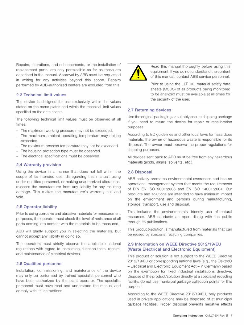
Figure 12: LLT100 system configuration options
1
2
4
3
1 2 3 4 5 6 7
1
21
2
2
1
22
1
1
A
B
C
4
C
3
C
2
C
DE
FG
I3.4 LLT100 transmitter configurations

18 OI/LLT-EN Rev. B | Operating Instruction
LLTLaser level transmitter
Category Name Number Name
A Process flanges 1 DIN 50 mm PN40, stainless steel, raised face
2 ASME 2 in. class 300, stainless steel, raised face
3 ASME 2 in. class 150, stainless steel, raised face
4 DIN 50 mm PN16, stainless steel, raised face
5 ASME 2 in. class 150 / DIN 50 mm PN16 bolt pattern, flat face, aluminum
6 ASME 2 in. class 150 / DIN 50 mm PN16 bolt pattern, flat face, stainless steel
7 Tri-clover 4 in., stainless steel
B Main body 1 Painted aluminum main body
2 Stainless steel main body
C Housing 1 Housing, stainless steel, 4 pins, M20
2 Housing stainless steel, 4 pins, 1/2 in. NPT
3 Housing aluminum, 4 pins, 1/2 in. NPT
4 Housing aluminum, 4 pins, M20
D Terminal block 1 Terminal block HART with heater, 4-wire, with surge
2 Terminal block HART, no heater, 2-wire, with surge
E Cover 1 Blind cover, aluminum
2 Blind cover, stainless steel
F Communication box 1 Display assembly, touch screen LCD
G Cover/display 1 Blind cover, stainless steel
2 Blind cover, aluminum
3 Window cover, stainless steel
4 Window cover, aluminum
H Plug 1 ATEX plug M20
2 ATEX plug 1/2 in. NPT

Operating Instruction | OI/LLT-EN Rev. B 19
4 Installation considerations
4.1 General information
The LLT100 is an optical, line of sight device that is used for non-contact distance measurement. There must be no obstacles directly in the beam path.
The LLT100 measures in engineering units (feet or meters) and there is no need for calibration prior to installation. The transmitter can simply be aimed directly towards an object and it will measure the real physical distance from its surface. Any special settings required by the user may be loaded into the device inside the work area or workshop prior to mounting the LLT100 outside.
Study these installation instructions carefully before proceeding. Failure to observe the warnings and instructions may cause a malfunction or personal hazard. Before installing the LLT100, check whether the device design meets the requirements of the measuring point from a measurement technology and safety point of view.
This applies with respect to:
– Explosion protection certification – Measuring range – Temperature – Operating voltage
The suitability of the materials must be checked with regards to their resistance to the media. This applies with respect to:
– Gasket – Process connection, isolating diaphragm, mounting screws
etc.
In addition, the relevant directives, regulations, standards, and accident prevention regulations and national standards must be observed. Measurement accuracy is largely dependent on correct installation of the LLT100. As far as possible, the
measuring setup should be free from critical ambient conditions such as large variations in temperature, vibrations, or shocks.
Attention – Property damage
If unfavorable ambient conditions cannot be avoided for reasons relating to building structure, measurement technology, or other issues, the measurement quality may be affected.
4.2 IP protection and designation
The housings for LLT100 are certified as conforming to protection type IP66/IP67 (according to IEC 60529) or Type 4X (according to NEMA 250).
The first number indicates the type of protection the integrated electronics have against the entry of foreign bodies, including dust: number 6 means that the housing is dust-proof (i.e., no ingress of dust).
The second number indicates the type of protection the integrated electronics have against the entry of water:
• Number 6 means that the housing is protected against water; specifically, against the effects of powerful jets.
• Number 7 means that the housing is protected against water; specifically, against the effects of temporary immersion in water under standardized water pressure and temporal conditions.
4.3 Environmental
The LLT100 should be installed in an area that is within the specified temperature range (see Appendix A – Technical Specifications on page 73), taking into consideration the enclosure ratings and the materials of construction.
Figure 13: Operating Temperature Limits
60 °C / 140 °F - 40 °C / - 40 °F

20 OI/LLT-EN Rev. B | Operating Instruction
LLTLaser level transmitter
4.4 Mounting considerations
Make sure to observe the suggested mounting arrangements and also the shown mounting arrangements that should be avoided. Refer to Figure 27 on page 32 and to Figure 29 on page 33.
4.4.1 LLT100 factory configuration consideration
The LLT100 in your hands has been factory calibrated to reflect the published declared performance specification; no further calibration is required in normal usage condition.
4.4.2 Hazardous area considerations
The LLT100 must only be installed in hazardous areas for which it is properly certified. The certification plate is permanently fixed on the neck of the LLT100 top housing. For specific hazardous area installation considerations, see chapter 9 Hazardous Area considerations on page 69.
Attention – Property damageGeneral risk for aluminum models used in zone 0. The enclosure contains aluminum and is considered to present a potential risk of ignition by impact or friction. Care must be taken into account during installation and use to prevent impact or friction.
4.4.3 Integral display rotation
When an optional integral display is installed, it is possible to mount the display in four different positions rotated clockwise or counterclockwise with 90° steps.
To rotate the LCD
1. Open the windowed cover (Hazardous area prescriptions must be respected).
2. Pull-out the display housing from the communication board.
3. Reposition the LCD connector according to the new desired position.
4. Push back the LCD module on the communication board.
Be sure that the four plastic fixing locks are properly in place.
For Ex d installations, please refer to note Important – Securing the housing cover in flameproof areas on page 44.
Operating Instruction | OI/LLT-EN Rev. B 21
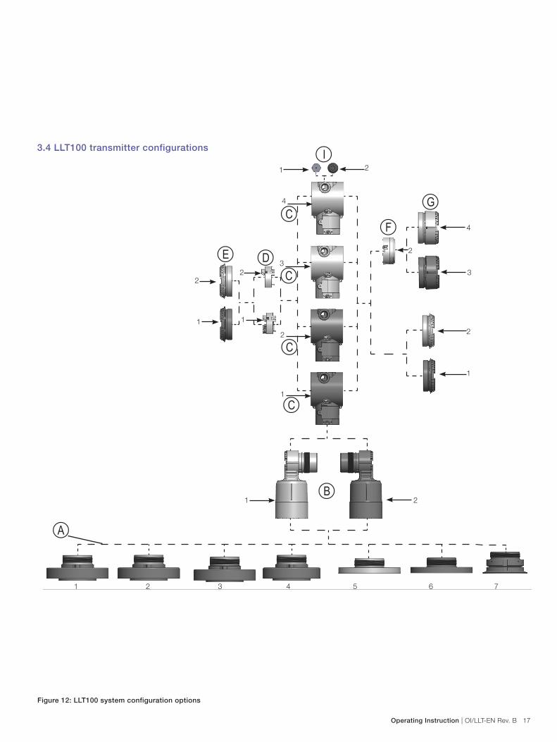
4.4.4 LLT100 housing rotation
To improve field access to the wiring or the visibility of the optional LCD, the LLT100 housing may be rotated from initial position -45° and + 90° and fixed in either of these position. A stop prevents the housing from being turned too far. In order to proceed with housing rotation, the housing stop tang-screw has to be unscrewed by approximately 1 rotation (do not pull it out) and, once the desired position has been reached, retightened.
WARNING – Property DamageThe LLT100 housing can only be rotated from its initial position -45° and + 90° and fixed in either of these position. Turning beyond these limits may permanently damage the LLT100 transmitter.
Figure 14: Housing rotation
Housing stop tang-screw
+90° -45°
22 OI/LLT-EN Rev. B | Operating Instruction
LLTLaser level transmitter
4.5 Unpacking
The product is supplied in a cardboard container with internal shock absorbing packaging. Check the entire box content for accessories that may be wrapped and may appear hidden. ABB recommends to keep the original packaging material to always transport the transmitter in the supplied packaging to reduce the chance of damage. If the original packing material is not kept and the LLT100 has to be returned to the manufacturer for repair, make sure to sufficiently protect the transmitter for transportation.
4.6 Handling
The product is designed to withstand many industrial environmental conditions. However, a few handling precautions will ensure reliable operation of the unit for extended periods of time.
– DO NOT DROP THE TRANSMITTER. – Remove dirt from the window with compressed air or if not
sufficient, clean with alcohol and optical wipes. – Do not install or connect with the power on. – Do not open the transmitter compartment or expose the
internal electronics to water or dirt. – Ensure that the cable glands or conduits are tight after
connecting the external cable. – Ensure that the lid to the terminal compartment is tight after
connections have been made. – Do not point the transmitter at the sun. – Do not open or modify the transmitter. – Store in a cool dry place. – Respect electrical specifications.
4.7 Installation steps and details
The LLT100 is delivered as an assembly. The one or more gaskets, bolts, washers and nuts are not included and have to be selected according to the process and/or national standard. Make sure to locate all bolts, nuts and washer and respect the appropriate order as detailed in Figure 15: Standard flat face flange LLT100 installation, ASME/DIN Universal on page 23.
Select the appropriate gasket for the application, i.e. a gasket that complies with the ASME B16.5 standard or the standard required by the user. The gasket and transmitter flange are to be selected according to the service condition of the application.
For all types of flanges:
Tighten the flange bolts in an alternating crisscross pattern to a torque value of one-fourth of the final bolting torque. Repeat this procedure several times, increasing the torque value each time by a fourth of the final torque value. After applying the final torque value, tighten each bolt again to allow for gasket compression.

Operating Instruction | OI/LLT-EN Rev. B 23
Number Process flange ASME 2 in./DIN 50 flat face, supplied by customer
1 4x HHCS 5/8-11 x 2 1/2 or 4x M16 x 2.0 x 60
2 4x Flat washer 5/8 or 4x flat washer M16
3 4x Hex nut 5/8-11 or 4x hex nut M16 x 2.0
4 Full face gasket 2 in. class 150 or DIN 50 PN 16 full face
5 Process flange ASME 2 in. class 150 flat face or flange DIN 50 PN16 flat face
All parts except for the LLT100 are to be supplied by customer.
4.7.1 Standard model
Figure 15: Standard flat face flange LLT100 installation, ASME/DIN Universal
1
2
3
2
5
4

24 OI/LLT-EN Rev. B | Operating Instruction
LLTLaser level transmitter
Number Process flange 2 in. Class 150 Process flange 2 in. Class 300 Process flange DIN 50 PN16 Process flange DIN 50 PN40
1 4x HHCS 5/8-11 x 3 1/2 8x HHCS 5/8-11 x 3 1/2 4x M16 x 2.0 x 60 4x M16 x 2.0 x 60
2 4x flat washer 5/8 8x flat washer 5/8 4x flat washer M16 4x flat washer M16
3 4x hex nut 5/8-11 8x hex nut 5/8-11 4x hex nut M16 x 2.0 4x hex nut M16 x 2.0
4 Ring gasket 2 in. class 150 Ring gasket 2 in. class 300 Ring gasket DIN 50 PN16 Ring gasket DIN 50 PN40
5 Process flange ASME 2 in. class
150 RF
Process flange ASME 2 in. class
300 RF
Process flange DIN 50 PN16 RF, Process flange DIN 50 PN40 RF
All parts except for the LLT100 are to be supplied by customer.
4.7.2 Pressure rated models
Figure 16: Pressure rated, raised face flange LLT100 installation with fused glass, here only the 4-bolt model is shown
1
2
32
5
4

Operating Instruction | OI/LLT-EN Rev. B 25
4.7.3 Tri-clover model
Figure 17: Tri-clover LLT100 installation
1
2
3
4
Number Tri-clover 4 in., stainless steel
1 Gasket sanitary clamp 4 in. prt
2 Quick clamp sanitary 4 in.
3 Clamp sanitary tube 4 in.
4 Tri-Clover LLT100 transmitter, compatible with ISO2852, DIN32676, ASME-BPE, TRI-CLAM, TRI-CLOVER
All parts except for the LLT100 are to be supplied by customer.

26 OI/LLT-EN Rev. B | Operating Instruction
LLTLaser level transmitter
Number Flange ASME 2"/DIN 50 FF, supplied by customer
1 4x HHCS 5/8-11 x 2 1/2 or 4x M16 x 2.0 x 60
2 4x Flat washer 5/8 or 4x flat washer M16
3 4x Hex nut 5/8-11 or 4x hex nut M16 x 2.0
4 Full face gasket 2" class 150 or DIN 50 PN 16 full face, to be supplied by customer
5 Flange ASME 2" class 150 full face or flange DIN 50 PN16 full face, to be supplied by customer
Figure 18: Laser beam details
4.7.4 Dusty conditions
In dusty conditions, it is strongly recommended that a Dust Tube be installed (see Appendix B – Accessories on page 75). In extremely dusty conditions, for example during a filling process if the signal is lost for too long, the measurement may be temporarily unavailable. Refer also to sections 6.10 Measurement modes and filter options on page 46 and 6.11.1 Easy Setup on page 49.
The dust tube is a very simple and effective device, designed to prevent dust settling on the lens. The LLT100 can be used in most dust present applications by using the dust tube accessory.
4.7.5 Foggy conditions
In foggy conditions, it is strongly recommended that the heated window option be used (see Appendix B – Accessories on page 75). In extremely foggy conditions, for example during a filling process if the signal is lost for too long, the measurement may be temporarily unavailable. Refer also to sections 6.10 Measurement modes and filter options on page 46 and 6.11.1 Easy Setup on page 49.
4.8 Alignment
The LLT100 is simple to install and align. It has a narrow and direct beam so there is no interference from nearby objects. The output beam is factory aligned perpendicular to the transmitter’s front window (90 ± 0.5).
The main consideration required when aligning the transmitter is a clear line of sight.
The LLT100 will measure off a surface that is rough or is at an oblique angle to the beam. There is no need to align the transmitter perpendicular to the material as it will not be affected by the cone up or down of the material. However, for liquid applications, mount the laser perpendicular as far as possible to the surface. A misalignment up to 5 degrees may be acceptable in very good conditions (short distance, smooth surface, clear light). For long distances a deviation of 1–2 degrees might be necessary for optimal performances.
The laser beam forms a rectangular shape. For example, at a 30 m distance, the beam is 20 cm by 3 cm. The long side of the rectangle is in line with the blocking screw, as indicated in Figure 18: Laser beam details on page 26. This screw is factory-secured and cannot be untightened. If there is an obstacle in the trajectory of the laser beam, make sure to align the obstacle parallel to the laser beam's long side by using the flange to rotate the whole instrument.
Blocking screw

Operating Instruction | OI/LLT-EN Rev. B 27
4.9 Mounting
The LLT100 produces a narrow, straight and invisible laser beam. It should be mounted facing directly towards the area to be measured with no obstacles directly in the beam path.
Mounting depends on the flange and process type varying from 8 mounting holes, 4 mounting holes or a clamp in the case of the tri-clover version. The transmitter can be bolted directly onto a flange or bracket. For the pressure-rated applications make sure to respect the national codes and/or certification regulations in terms of mounting, bolts and gaskets.
In applications where dust may be present (even in very small quantities) it is recommended that a dust tube accessory be used.
Helpful tip
The LLT100 may receive stronger signals in subdued lighting and dark conditions than it does in direct sunlight.
Attention – Property damage
Exposure to some chemicals may degrade the window or the sealing properties of the LLT100 or degrade the lens.
DANGER – Serious damage to health / risk to life
Explosion hazard. Do not open or disconnect equipment when a flammable or combustible atmosphere is present.
Attention – Property damage
Always use thread sealant or conduit seal in order to maintain enclosure Type 4X and IP66/IP67 rating.
Attention – Property damage
Avoid mounting the transmitter close to a stream of material that may fall in front of it. Avoid aiming the transmitter down long narrow pipes that have rough inner walls. Ensure that the transmitter never points directly at or near the sun. Check the operation over the full range of conditions to be measured after installing.
4.10 Alignment with the external commissioning laser device (if purchased)
If too many obstacles are present around the beam path, the external commissioning laser device can help to align the LLT100. Install the external commissioning laser device on the process flange or bracket and screw in place. Make sure two AAA type batteries are in the device. Turn on the external commissioning laser device and verify the alignment.
94.5
52
40
157
15
R78.5
SCREW SIZE 5/8" (M16)BOLT PATTERN NPS2"-CL150 & DIN50 PN40
0051-13-1-00013-01 LASER POINTER FLANGE LLT100
Figure 19: External commissioning laser device
Warning – Laser radiation
DO NOT STARE INTO BEAM OR EXPOSE USERS TO TELESCOPIC OPTICS
CLASS 2M LASER PRODUCT (650 nm)
CW laser power <1 mW. Complies with FDA performance standards for laser product except for deviations pursuant to Laser Notice No. 50, dated June 24, 2007.
When the alignment is correct, unscrew the external commissioning laser device and install the LLT100 in place. When installing the LLT100, make sure to use the appropriate screws, bolts and washers according to your process.

28 OI/LLT-EN Rev. B | Operating Instruction
LLTLaser level transmitter
Adjustable pivot bracket
Bolt pattern
diameter ø121 mm (4.8 in.)
167 mm (6.6 in.)
249 mm (9.8 in.)
+/- 30° rotation angle
+/- 10° rotation angle
22 mm (0.9 in.)
45 mm (1.75 in.)
45 mm (1.75 in.)
9 mm (0.4 in.)
8X ø18 mm (0.7 in.)
8X ø8.8 mm (0.3 in.)
185 mm (7.28 in.)
Figure 20: Adjustable pivot bracket with measurements

Operating Instruction | OI/LLT-EN Rev. B 29
249 mm (9.8 in.)
Figure 21: Adjustable Mounting Bracket assembly
Dust tubes
Purge Ring
Adjustable pivot bracket
Gasket
Gasket
Gasket
LLT100 transmitter
Figure 22: Assembly with adjustable pivot bracket and dust tubes (screws, washer, bolts and gaskets are to be supplied by customer accord-ing to process)

30 OI/LLT-EN Rev. B | Operating Instruction
LLTLaser level transmitter
Figure 23: Cooling platform with 4 different process flanges
Cooling platform
Number Process flange Universal Process flange 2 in.
Class 150
Process flange 2 in.
Class 300
Process flange DIN 50
PN40
Process flange DIN 50
PN16
1 Process flange universal
fit to 2 in. NPS-class 150
& DIN50
Process flange ASME
2 in. class 150 RF
Process flange ASME
2 in. class 300 RF
Process flange DIN 50
PN40 RF
Process flange DIN 50
PN16 RF
2 O-ring
3 Cooling tube
4 Universal flange flat face SS
5 Ring gasket 2 in. class 150 & DIN50
6 4x HHCS 5/8-11 x 3 1/2 4x HHCS 5/8-11 x 3 1/2 8x HHCS 5/8-11 x 3 1/2 4x HHCS 5/8-11 x 3 1/2 4x HHCS 5/8-11 x 3 1/2
All parts except for the LLT100 are to be supplied by customer.
6
152–165 mm* 6.0–6.5 in.
165 mm 6.5 in.
5
1
2
4
2
3
289 mm 11.4 in.
234 mm 9.2 in.
With pressure rated flange *Diameter varies from class150 to class 300)
With universal flange

Operating Instruction | OI/LLT-EN Rev. B 31
94.5
52
40
157
15
R78.5
SCREW SIZE 5/8" (M16)BOLT PATTERN NPS2"-CL150 & DIN50 PN40
0051-13-1-00013-01 LASER POINTER FLANGE LLT100
Figure 24: Swivel flange assembly (watertight)
Figure 25: External commissioning laser device
Swivel mount
LLT100
Laser
Fasten to process flange
Swivel mount assembly
Process flange/bracket

32 OI/LLT-EN Rev. B | Operating Instruction
LLTLaser level transmitter
Figure 26: LLT100 with purge ring and dust tubes
Figure 27: Suggested mounting arrangements for solid materials
257 mm (10 in.)
165 mm (6.5 in.)
LLT100
Purge ring
Dust tubes
ø 165 mm (6.5 in.)
Thickness 12.7 mm (0.5 in.)
Air inlet 1/4 (6 mm)barbed tube fitting
✔ ✔

Operating Instruction | OI/LLT-EN Rev. B 33
Figure 28: Mounting arrangements to avoid for solid materials
Figure 29: Suggested Mounting arrangements for liquids (on the left) and mounting arrangements to avoid for liquid materials (on the right)
✔

34 OI/LLT-EN Rev. B | Operating Instruction
LLTLaser level transmitter
5 LLT100 wiring
WARNING – General risks
Observe the applicable regulations governing electrical installation. Connections must only be established in an unpowered state. Secure the breaker while working on the circuit to avoid accidental power-up. For continuous installation protection, a double insulation power supply (5kV or higher) shall be used for the current loop. The power supply shall be equipped with a short circuit protection function and along with an auto restart. For external installations exposed to lightning, a transient voltage suppression module or a galvanic isolator shall be installed with adequate grounding before entering a building with a cable to avoid personnel injury or property damage. Refer to local building code and electrical code for proper practices. The same power supply can be used for both the 4-20mA loop and the window heater. A second pair of wire shall be used to avoid excessive voltage drop exceeding LLT100 electrical specifications.
Electrical shock can result in death or serious injury. Avoid contact with the leads and terminals.
Do NOT make electrical connections unless the electrical code designation stamped on the LLT100 data plate agrees with the classification of the area in which the LLT100 is to be installed. Failure to comply with this warning can result in fire or explosion.
For 2-wire wiring, refer to Figure 33: LLT100 Terminal compartment, no heater – 2 wires on page 38 and Figure 36: Typical connection for 2 wires on page 39.
For 4-wire (with heater option) refer to Figure 32: LLT100 Terminal compartment, with heater option – 2 + 2 wires on page 38 and Figure 35: Typical connection for 2 + 2 wires
(alternate wiring) on page 39.
5.1 Cable connection
The LLT100 has a ½ inch NPT/M20 cable gland entry. A suitably certified ½ inch NPT/M20 cable gland being certified to either Ex db or Ex tb according to the installation, and having an IP rating of at least IP66/IP67 shall be used. The cable glands supplied by ABB are ATEX and CE certified and meet the above requirements.
These cable glands can only be used with braided shield cables. When installing them, make sure to fold the cable shield over the O-ring which presses the braiding against the inside wall of the body, this ensures good contact.
Important
For cable glands that are not supplied by ABB, please refer to your supplier’s data sheet for proper installation.
Important
Wires and cables glands shall be rated at least 90°C.
WARNING – General risks
ABB does not assume any responsibility for non ATEX or CE certified cable glands or adaptor that do not meet the above requirements.
Important
It is the costumer's responsibility to use appropriate cable gland, screw plug, lube and/or sealant for the cable entry ports.
The installer assumes responsibility for any other type of sealing medium used. At this point, we wish to draw your attention to the fact that increased force will be required to unscrew the housing cover after an interval of several weeks.
This is not caused by the threads, but instead is due solely to the type of gasket.
DANGER – Serious damage to health/risk to lifeDuring installation, current to the 4-20 mA circuit should be interrupted for 60 seconds as otherwise it may cause a permanent error.

Operating Instruction | OI/LLT-EN Rev. B 35
5.2 Analog output (HART) LLT100 wiring
+
-+
+
- -
+M
-Kent-Taylor
0
435 6 7 8
910
2040
0
60100%
2 80
691HT
A B C
1D E F
2G H I
3
J K L
4M N O
5P Q R
6
S T U
7V W X
8Y Z #
9
@ % & /0
+-
PV
REVIE W SERIALLINK
TRI M
F1 F2 F3 F4
CONF
-
21
+
1
2
5
37
6
4
Figure 30: HART LLT100 connection scheme
Number Description
1 Inner ground termination point
2 External ground termination point
3 Cooling tube
4 Line loadr
5 Remote indicator
6 Power source
7 DCS/PLC
HART hand-held communicator may be connected at any wiring termination point in the loop, providing the minimum resistance is 250 ohm. If this is less than 250 ohm, additional resistance should be added to allow communications. The handheld terminal is connected between the resistor and the LLT100, not between the resistor and power source.
5.3 Supply requirement
For signal/power connection use twisted, stranded pairs of wiring no 18 to 22 AWG / 0.8 to 0.35 mm2 ø up to 5,000 feet (1500 meters). Longer loops require larger wire.
If a shielded wire is used, the shield should be grounded only at one end, not both ends. When wiring at LLT100 end, use the terminal located inside the housing marked with the appropriate sign.
The 4 to 20 mA DC output signal and the DC power supply to the LLT100 are carried from the same pairs of wires.
The supply voltage at the LLT100 terminals must be between the limits of 15.5 and 42V DC. If using 250 W for HART, limits are 21 V to 42 V if there is no load on the line.
For maximum power supply voltage please refer to the top identification plate of the LLT100.
The maximum current loop length usable with HART communication can be calculated using the following formula:
65 x 106 R x C
L =Cf + 10000 C
–
Where:
L = Line length in meters
R = Total resistance in Ω (ohms)
C = Line capacitance in pF/m
Cf = Maximum internal capacitance of the HART field devices located in the circuit, in pF
Avoid routing cables with other electrical cables (with inductive load, motors, etc.) or near large electrical equipment.
36 OI/LLT-EN Rev. B | Operating Instruction
LLTLaser level transmitter
5.4 Wiring procedure
DANGER – Sharp surfaceDo not grab the transmitter by the threaded interface. The threaded edges are sharp and there is a risk of personal injury.
To wire the LLT100
1. Remove the temporary plastic cap from one of the two electrical connection ports located at both sides in the upper part of the LLT100 housing.These connection ports may have a 1/2 inch internal NPT or M20 threads. Various adaptors and bushings can be fitted to these threads to comply with plant wiring (conduit) standards.
2. Remove the housing cover on the “field terminals” side. See the indication on the label on top of the housing. In an explosion proof/flameproof installation, do not remove the LLT100 covers when power is applied to the unit.
3. Run the cable through the cable gland and the open port.4. Connect the positive lead to the + terminal, and the negative
lead to the – terminal in the case of HART.5. Plug and seal the electrical ports. Make sure that when
the installation has been completed, the electrical ports are properly sealed against entry of rain and/or corrosive vapors and gases.
WARNING – General risks
Cable, cable gland and unused port plug must comply with the intended type of protection (e.g. dust proof, flameproof, etc.) and degree of protection (e.g. IP66/IP67 according to IEC EN 60529 or Type 4X according to NEMA 250). In particular, for explosion proof installation, remove the red temporary plastic cap and plug the unused opening with a plug certified for explosion containment with appropriate rating.
WARNING – General risks
If required by national electrical codes, a circuit breaker or switch in the building installation, marked as the disconnect switch shall be in close proximity to the equipment and within easy reach of the operator.
WARNING – General risks
In an industrial environment with extreme presence of EMI (electromagnetic interference), such as rock quarries, mines or large chemical plants, ABB recommends the use of noise filters on the DC power supply to the transmitter and signal isolators on the 4-20 mA output.
1. If applicable, install wiring with a drip loop. Arrange the drip loop so the bottom is lower than the conduit connections and the LLT100 housing.
2. Put back the housing cover, turn it to seat the O-ring into the housing and then continue to tighten by hand until the cover contacts the housing metal-to-metal. For Ex d (explosion proof) installation, see note Important – Securing the housing cover in flameproof areas on page 44.
5.5 Grounding
The LLT100 should be grounded or earthed in accordance with national and local electrical codes. Ground connection is mandatory for surge protector equipped devices in order to ensure proper functioning.
Protective grounding terminals (PE) are available outside and/or inside the housing of the LLT100. Both ground terminals are electrically connected and it is up to the user to decide which one to use. The most effective LLT100 case grounding method is direct connection to earth ground with impedance equal or less than 5 mOhm. The internal ground can be seen on Figure 32 on page 38.
Figure 31: External ground connection on LLT100 housing

Operating Instruction | OI/LLT-EN Rev. B 37
5.6 Surge protector equipped terminal blockLLT100 must be connected using the grounding terminal (PE), by means of a short connection with the equipotential bonding.
Equipotential bonding conductor must have 4.00 mm2 of maximum cross-section.
WARNING – Bodily injury
For continued protection, the terminal board needs to be replaced if the installation shows any sign of damage resulting from direct or indirect lightning.
Important
Test voltage withstand capability can no longer be ensured when this protective circuit is used.
5.7 Common mode voltages
The LLT100 with surge protection will not work if exposed to common mode voltage in excess of the maximum allowed supply voltage.

38 OI/LLT-EN Rev. B | Operating Instruction
LLTLaser level transmitter
5.8 Electrical connections5.8.1 With heater
5.8.2 Without heater
Figure 32: LLT100 Terminal compartment, with heater option – 2 + 2 wires
Figure 33: LLT100 Terminal compartment, no heater – 2 wires
Internal protective earth (ground)
Internal protective
earth (ground)
Cover lockscrew M4
Cover lock
screw M4
External DC supply for lens heater option: +24 V 3 W at 24 Vdc
0 V (return)
External ground
termination point
External ground
termination point
Pos ( + )
Pos ( + )
Neg ( – )
Neg ( – )
*Optional ext. meter (+)
*Optional ext. meter (+)

Operating Instruction | OI/LLT-EN Rev. B 39
Figure 35: Typical connection for 2 + 2 wires (alternate wiring)Figure 34: Typical connection for 2 + 2 wires
Figure 36: Typical connection for 2 wires
(24 Vdc, 3W)
(24 Vdc)
40 OI/LLT-EN Rev. B | Operating Instruction
LLTLaser level transmitter
6 Commissioning and operationOnce the LLT100 has been installed, it is put into operation by switching on the operating voltage.
Check the following before switching on the operating voltage:
– Process connections – Electrical connection
The LLT100 can then be put into operation.
6.1 Quick start guide
6.1.1 Setup procedure1. Connect the power and 4/20 mA wires to the LLT100 laser
level transmitter.2. For the standard LLT100 unit refer to section 5.8 Electrical
connections on page 38.3. Turn the power on.4. Establish communication with the LLT100 unit. Refer to
section 6.4 Optional integral LCD HMI with keypad (menu-controlled) on page 42 or through the HART protocol.
5. Set a vessel height that corresponds to your process.6. Set 4 mA and 20 mA set points defined as vessel full and
vessel empty. Refer to sections 6.11.1 Easy Setup on page 49 and 6.11.2 Device Setup menu on page 50.
7. Set the measurement mode, i.e. standard/normal, clear liquid and positioning or dust. Measurement mode is ap-plication oriented mode of operation and it is set accord-ing to the application the unit is used for. Refer to sec-tions 6.11.1 Easy Setup on page 49 and 6.11.2 Device Setup menu on page 50.
8. From the main menu, start the transmitter.
6.2 Configuration with the PC/laptop or handheld terminal
A graphical user interface (DTM) is required for configuration of the LLT100 using a PC or laptop. For operating instructions, please refer to the software description.
The LLT100 can be configured using one of the following devices:
– Any DTM based software for HART instruments configuration, providing it is compatible with EDD or DTM.
– Configuration of the LLT100 using the integral user interface (LCD HMI) with keypad (menu-controlled).
– Hand held terminals, provided the corresponding protocol has been downloaded and enabled in the terminal.
– Configuration of the parameters for the lower and upper range values (via the Zero and Span buttons), without an integral user interface (LCD HMI) (refer to section 6.13 Local push buttons functionality on page 63.
You can use a handheld terminal to read out or configure/calibrate the LLT100. If a communication resistor is installed in the connected supply unit, you can clamp the handheld terminal directly along the 4...20 mA line. If the line lacks a communication resistor, you will need to install one (min. 250 Ω). The handheld terminal is connected between the resistor and the LLT100, not between the resistor and the supply unit.
6.3 Factory settings
The LLT100 is calibrated at the factory. The LLT100 is delivered with the following default configuration:
Parameter Factory setting
Measurement mode Standard
Vessel height 200 m
Vessel empty (LRV) 0.0
Vessel full (URV) Vessel height
Damping 1 second
No measurement period 15 seconds
4-20 mA output (PV) Ullage
PV unit Meter
LLT100 failure (alarm) Low alarm (3.6 mA)
ImportantEvery of the configurable parameters can easily be modified either via the optional LCD HMI, with an HART handheld terminal or a compatible software solution.

Operating Instruction | OI/LLT-EN Rev. B 41
A - LLT100
B - Supply unit (communication resistor provided in supply unit)
Figure 37: Communication setup with handheld terminal
A - LLT100
B - Supply unit (communication resistor not provided in supply unit)
Figure 38: Connection examples with communication resistor in the connection line
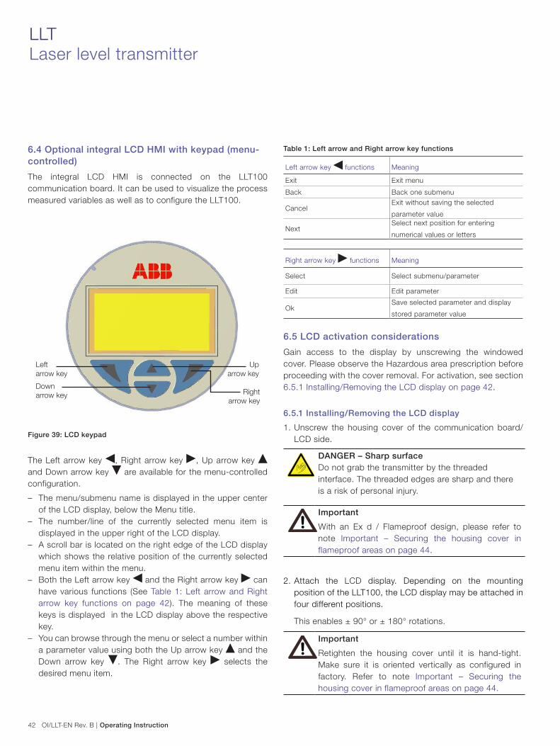
42 OI/LLT-EN Rev. B | Operating Instruction
LLTLaser level transmitter
6.4 Optional integral LCD HMI with keypad (menu-controlled)
The integral LCD HMI is connected on the LLT100 communication board. It can be used to visualize the process measured variables as well as to configure the LLT100.
Figure 39: LCD keypad
The Left arrow key , Right arrow key , Up arrow key and Down arrow key are available for the menu-controlled configuration.
– The menu/submenu name is displayed in the upper center of the LCD display, below the Menu title.
– The number/line of the currently selected menu item is displayed in the upper right of the LCD display.
– A scroll bar is located on the right edge of the LCD display which shows the relative position of the currently selected menu item within the menu.
– Both the Left arrow key and the Right arrow key can have various functions (See Table 1: Left arrow and Right arrow key functions on page 42). The meaning of these keys is displayed in the LCD display above the respective key.
– You can browse through the menu or select a number within a parameter value using both the Up arrow key and the Down arrow key . The Right arrow key selects the desired menu item.
Table 1: Left arrow and Right arrow key functions
Left arrow key functions Meaning
Exit Exit menu
Back Back one submenu
CancelExit without saving the selected
parameter value
NextSelect next position for entering
numerical values or letters
Right arrow key functions Meaning
Select Select submenu/parameter
Edit Edit parameter
OkSave selected parameter and display
stored parameter value
6.5 LCD activation considerations
Gain access to the display by unscrewing the windowed cover. Please observe the Hazardous area prescription before proceeding with the cover removal. For activation, see section 6.5.1 Installing/Removing the LCD display on page 42.
6.5.1 Installing/Removing the LCD display
1. Unscrew the housing cover of the communication board/LCD side.
DANGER – Sharp surfaceDo not grab the transmitter by the threaded interface. The threaded edges are sharp and there is a risk of personal injury.
Important
With an Ex d / Flameproof design, please refer to note Important – Securing the housing cover in flameproof areas on page 44.
2. Attach the LCD display. Depending on the mounting position of the LLT100, the LCD display may be attached in four different positions.
This enables ± 90° or ± 180° rotations.
Important
Retighten the housing cover until it is hand-tight. Make sure it is oriented vertically as configured in factory. Refer to note Important – Securing the housing cover in flameproof areas on page 44.
Left arrow key
Up arrow key
Down arrow key Right
arrow key

Operating Instruction | OI/LLT-EN Rev. B 43
Figure 40: Windowed front cover and LCD display
6.5.2 Through The Glass (TTG) activation considerations
The TTG technology allows the user to activate the keypad on the HMI without the need of opening the windowed cover of the LLT100. The capacitive pick-ups will detect the presence of your finger in front of the respective key activating the specific command. At the LLT100 power-on the HMI automatically calibrates its sensitivity. It is mandatory for the proper functioning of the TTG HMI that the cover is correctly tightened at power-on.
When the cover has been removed to access the communication board, it is recommended to power off and power-on again the LLT100 once the windowed cover has been set in place and properly tightened.
6.5.3 Activation procedure for TTG and LCD
The HMI features four keys (see Figure 39: LCD keypad on page 42) that allow the navigation through the various functions.
Press the Right arrow key within one second to access the HMI menu or press the Left arrow key to access the instantaneous diagnostic messages.
ImportantDo not operate the TTG display for 30 seconds after the LLT100 power-on. During this period of time, the LLT100 is calibrating the capacitive switches.
6.6 Analog and HART Communication models
If the measured distance falls within the values indicated on the name plate, the output current will be between 4 and 20 mA. If the measured distance falls outside the set range, the output current will be between 3.8 mA and 4 mA if the range is undershot or between 20 mA and 20.5 mA if the range is overshot (depending on the respective configuration).
6.7 Standard setting for normal operation 3.8 mA / 20.5 mA
In order to prevent errors in level measurements in the lower range, it is possible to set a “cut off point” via the optional LCD integral displays with keypad or via the graphical user interface.
A current that is less than 4 mA or grater than 20 mA may also indicate that the microprocessor has detected an internal error. In this case the alarm output can be configured both via the local LCD with keypad, via an external Hart hand held terminal or via a DTM based configuration tool.
6.8 Standard setting for error detection (alarm) 3.6 mA / 21 mA
The graphical user interface (DTM) or the LCD integral display, if installed, can be used to diagnose the error.

44 OI/LLT-EN Rev. B | Operating Instruction
LLTLaser level transmitter
Important
A brief interruption in the power supply results in initialization of the electronics (program restarts).
IMPORTANT – Alarm current – Lower limit: 3.6 mA (configurable from 3.6 to 3.8
mA) – Upper limit: 21 mA (configurable from 20.5 mA to
22 mA), limited to 22 mA for HART Safety; apply for electronics release 7.1.15 or later)
Factory setting: high alarm current (21.0 mA)
During power-up period the LLT100 uses 21 mA.
Important – Securing the housing cover in flame-proof areasEach of the front faces of the electronics housing features a locking screw (hex-head socket screw) on the bottom side:
– Install the housing cover to the housing by hand-tightening it.
– Turn the locking screw counterclockwise to secure the housing cover. This involves unscrewing the screw until the screw head stops at the housing cover.
6.9 HMI menu structurePress the Right arrow key within one second to access the HMI menu or press the Left arrow key to access the instantaneous diagnostic messages.
The HMI menu is divided in the following sections which can be selected by pressing the Up arrow key and Down arrow key , once on the display, the desired sub-menu icon will be visualized. Confirm your selection with the Right arrow key [SELECT function].
Follow the instruction on the screen to perform the configuration of the different parameters.
The Easy Setup menu allows the verification and the parameterization of the basic configuration of the LLT100. The menu driven structure will guide you to the choice of the interface language, measurement mode, vessel height, sensor offset, 4–20 mA output (PV), the engineering units, the URV and LRV (Upper range value and lower range value), filling rate enabled or not and he tag number configuration.
The Device Setup menu allows the verification and the parameterization of the entire device. The menu driven structure includes the enabling the write protection, setting process variables (unit, LRV and URV), (linearization and output scaling (unit according to the measurement and LRV/URV). The last selectable sub-menu allows user to reset all the parameters to the default configuration.

Operating Instruction | OI/LLT-EN Rev. B 45
The Display menu allows to set up different functions relevant to the display itself. The menu driven structure will guide you through the choice of some functional aspects as the display language and contrast. Moreover, it is possible to choose in detail what you want to see on the display: one or two lines with or without bar graph. Inside this menu there is the possibility of setting a protection password (security) and the display scaling (linearization type, unit, LRV, URV). Display revision number available.
The Process Alarm menu allows to the configure the process alarm. The menu driven structure will guide you through the choice of the fail safe functions such as the saturation limits and the fail level (upscale or downscale).
The Calibrate menu allows the local calibration of the transmitter. The menu driven structure will guide you through the choice of transmitter trimming (low or high), the output setting (set to 4 or 20 mA) and at the end you can reset these parameters (to factory transmitter trimming, to user transmitter trimming or to factory output trimming).
The Diagnostic menu allows you to monitor diagnostics messages related to level variables, output current and output percentage. The menu driven structure will also guide you through the loop test (set 4 and 20 mA and set the output value).
The Device Info menu gives you all the information about the device. The menu driven structure will show you the transmitter type, the hardware and software revisions, the high and low transmitter limits as well as the minimum applicable span.
The last section of this structured and driven menu, the Communication menu, gives you the possibility of changing the communication tag and the MULTI-DROP mode with HART address numbers of the device.

46 OI/LLT-EN Rev. B | Operating Instruction
LLTLaser level transmitter
6.10 Measurement modes and filter options
Measurement mode Description Application
Standard The standard measurement mode is designed for maximized
precision under regular operating conditions.
Use for most solid applications and opaque liquid applica-
tions without dust or vapor.
Clear liquid This mode corresponds to the standard measurement mode
with an additional bottom-of-the-tank detection algorithm.
Use for transparent liquid applications in which the bottom of
the tank is visible through the liquid surface.
Positioning The positioning measurement mode features a special
calibration designed to work with retroreflector panel targets.
This mode also features an enhanced double-reflection
detection algorithm.
Use for positioning applications where the sensor aims at a
highly-reflective retroreflector panel.
Note: Only use when the target is a retroreflector panel. For
positioning applications with other types of targets, use the
standard measurement mode.
Dust & vapor This measurement mode uses an algorithm that improves
reliability in high dust and vapor conditions.
Use for applications with heavy dust or vapor conditions.
Note: To maximize precision, we suggest to use standard or
clear liquid mode in applications with neither dust nor vapor.
Filter option Description Application
Fill rate This corresponds to the maximum filling rate of the process.
The fill rate value is used to limit the maximum possible rate
of change of the level measurement reading during filling.
Warning: The fill rate must be set to maximum filling rate
of the process. Any change in level that is faster than the
entered fill rate will be smoothed out by the sensor.
Use in applications where heavy dust or vapor can severely
decrease the visibility of the level surface.
Use in applications in which the laser beam can be tempo-
rarily obstructed (by agitators, filling material, etc.).
Drain rate This corresponds to the maximum draining rate of the
process. The drain rate value is used to limit the maximum
possible rate of change of the level measurement reading
during draining.
Warning: The drain rate must be set to maximum draining
rate of the process. Any change in level that is faster than
the entered drain rate will be smoothed out by the sensor.
Use in clear liquid applications where the bottom of the tank
is visible through the surface.
Useful for liquid applications in highly reflective stainless
steel vessels.
Median filter LLT100 measurements can be noisy as a result of the
process.
The median filter is designed to filter out noisy measurement
spikes. The value entered corresponds to the median filter
buffer size. The last measurements are kept in the buffer and
the sensor returns the median value of the buffer. The buffer
size can range from 2 to 25.
Use for filtering out measurement noise in applications with
fast transients, such as rapidly varying processes, position-
ing applications, etc.
Use for discarding occasional false measurements resulting
from temporary laser beam obstruction, or any other occa-
sional unwanted reflection that might occur in the process.
Damping LLT100 measurements can be noisy as a result of the
process.
The damping filter is designed to smooth out measurement
noise. The value entered corresponds to the damping time
constant, and can range from 1 s to 3600 s.
Use for smoothing out measurement noise in applications
with slow dynamics (e.g. liquid with slow waves).

Operating Instruction | OI/LLT-EN Rev. B 47
Filter option Description Application
No measurement period The no measurement period is a parametrizable amount of
time (between 2 s and 99999 s) during which the sensor, in
the absence of a reliable measurement, will predict the level
based on the current trend and/or fill rate.
Note: If the fill rate filter option is enabled, the sensor will
use the fill rate to predict the level measurement. Otherwise,
it will predict the level using the estimated current trend.
Note: After the no measurement period is over, if no reliable
measurement is still detected, the sensor will produce a
TARGET LOST error.
Use for agitated liquid applications. For these applications, a
value of the order of 10 s should be enough to guarantee a
good level reading stability.
Useful for applications where heavy dust or vapor can
severely decrease the visibility of the level surface. For these
applications, enter a value corresponding to the typical
surface obscuration time.
Useful for applications in which the laser beam can be tem-
porarily obstructed (by agitators, rotating blades, filling mate-
rial, etc.). For these applications, enter a value correspond-
ing to the typical laser beam obstruction time.

48 OI/LLT-EN Rev. B | Operating Instruction
LLTLaser level transmitter
6.11 General ModelThe diagram below shows the parameters that are used to define the distances and settings used throughout the menu.
Figure 41: General model
Vessel full (20 mA)
Level calibration point 0Level calibration point 0
Level calibration point 1Level calibration point 1
Vessel empty (4 mA)
Vessel height
Sensor offset
Ullage
Level
Mea
sure
d le
vel
Cal
cula
ted
real
leve
l

Operating Instruction | OI/LLT-EN Rev. B 49
6.11.1 Easy Setup
Press key and select the language. After entering the set-
tings, press key to move to the next menu item.
Press key and select the measurement mode with keys
and . After entering the settings, press key to
move to the next menu item.
Press key and select the measurement mode with keys
and . After entering the settings, press key to
move to the next menu item.
Press key and adjust vessel height with keys and
. To move to next digit use key . Set settings with key
. Make sure to respect the indicated min and max. After
entering the settings, press key to move to the next
menu item.
Press key and adjust vessel height with keys and
. To move to next digit use key . Set settings with key
. Make sure to respect the indicated min and max. After
entering the settings, press key to move to the next menu
item.
Press key and adjust vessel height with keys and
. To move to the next digit use key . Set settings with
key . Make sure to respect the indicated min and max.
After entering the settings, press key to move to the next
menu item.
Press key and adjust vessel height with keys and
. To move to next digit use key . Set settings with key
. Make sure to respect the indicated min and max. After
entering the settings, press key to move to the next menu
item.
Press key . Scroll the eng. units list with keys and
. Select with key key. Press key to move to the next
menu item.
Press key . Scroll the eng. units list with keys and
. Select using key . Press key to move to the next
menu item.
Once in the alphabetic menu use the “next” command by
pressing key to position the cursor on the character that
you want to change. Scroll the character list with and
, once on the selected one select “next” by pressing key
. Once completed select “Ok” by pressing key .
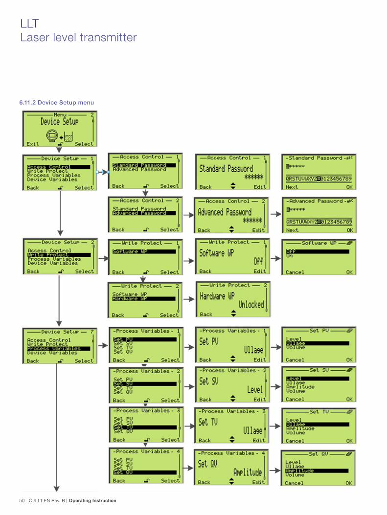
50 OI/LLT-EN Rev. B | Operating Instruction
LLTLaser level transmitter
6.11.2 Device Setup menu

Operating Instruction | OI/LLT-EN Rev. B 51

52 OI/LLT-EN Rev. B | Operating Instruction
LLTLaser level transmitter
6.12 Custom linearization curve
The custom linearization curve function is always used to convert level to volume in all applications. In tanks with an irregular shape (Cylindrical lying tank or spherical tank), it can be registered to a freely identifiable transfer function with a maximum of 22 base points. The first point is always the zero point, the last point is always the final value. Neither of these points can be altered.
A maximum of 20 points can be freely entered in between.
These points have to be defined by extrapolating the tank filling table data and reducing them to 22 points. Once identified, the 22 points will need to be uploaded into the device by either using an HART hand held terminal or a proper configuration software like Asset Vision Basic.

Operating Instruction | OI/LLT-EN Rev. B 53

54 OI/LLT-EN Rev. B | Operating Instruction
LLTLaser level transmitter
6.12.1 Display Setup menu
Example
All operator
pages can be
customized as
per requirement.

Operating Instruction | OI/LLT-EN Rev. B 55

56 OI/LLT-EN Rev. B | Operating Instruction
LLTLaser level transmitter
6.12.2 Process alarmsThe Process alarm menu allows the complete configuration of the analogue output for the saturation and failure alarm. The output signal ranges from 4 to 20 mA when the process variable is within the calibrated span limits.
When the process variable (PV) is below the LRV (lower range value), the signal is driven to the “Low Saturation” limit (configurable).
When the PV is above the URV (upper range value), the signal is driven to the “High Saturation” limit (which is also configurable).
When the transmitter diagnostic detects a failure, the signal is driven upscale or downscale according to the user preferences (the failure direction is selected via the dip switches number 4 and 5 on the communication board). The exact value to which the signal is driven can be configured via the Process alarm menu (Alarm limits).
As a convention, the Low Alarm limit must be lower than the “Low Saturation” limit and the High Alarm limit must be higher than than the ‘High Saturation” limit.
Figure 42: Limits variables diagram
Vessel height
Ullage
Level
Alarm High High
Alarm High
Alarm Low Low
Alarm Low

Operating Instruction | OI/LLT-EN Rev. B 57
(For the Process Alarm Limits submenu instructions, see page 58.)
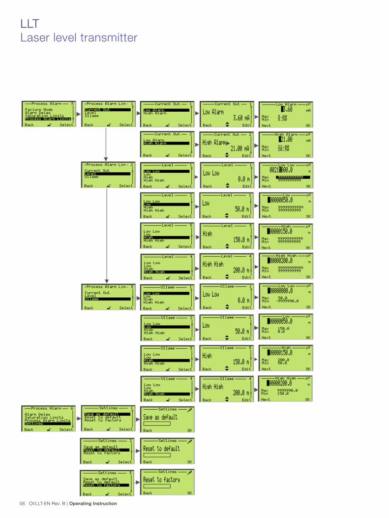
58 OI/LLT-EN Rev. B | Operating Instruction
LLTLaser level transmitter

Operating Instruction | OI/LLT-EN Rev. B 59
6.12.3 CalibrateThe calibration function allows to recalculate a measured level, which may be wrong because the LLT100 is installed at an angle, to the true level based on the known vessel dimension and angle.

60 OI/LLT-EN Rev. B | Operating Instruction
LLTLaser level transmitter
6.12.4 Diagnostics

Operating Instruction | OI/LLT-EN Rev. B 61
6.12.5 Device info

62 OI/LLT-EN Rev. B | Operating Instruction
LLTLaser level transmitter
6.12.6 Communication
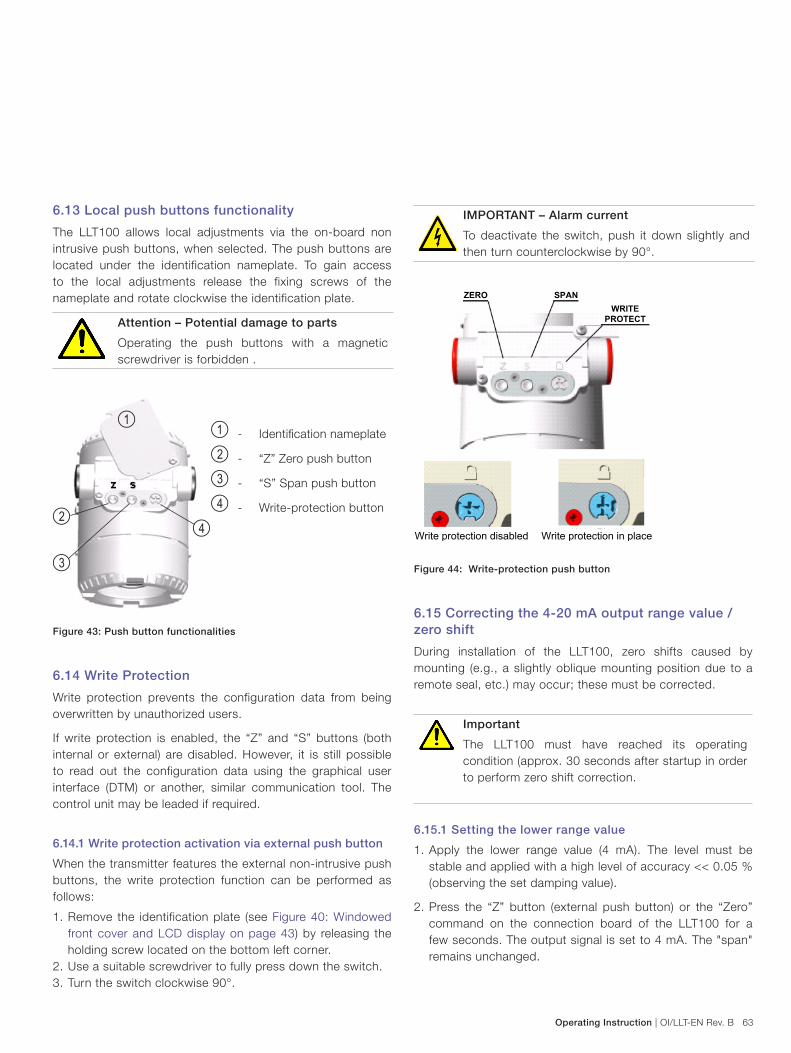
Operating Instruction | OI/LLT-EN Rev. B 63
6.13 Local push buttons functionality
The LLT100 allows local adjustments via the on-board non intrusive push buttons, when selected. The push buttons are located under the identification nameplate. To gain access to the local adjustments release the fixing screws of the nameplate and rotate clockwise the identification plate.
Attention – Potential damage to parts
Operating the push buttons with a magnetic screwdriver is forbidden .
Figure 43: Push button functionalities
6.14 Write Protection
Write protection prevents the configuration data from being overwritten by unauthorized users.
If write protection is enabled, the “Z” and “S” buttons (both internal or external) are disabled. However, it is still possible to read out the configuration data using the graphical user interface (DTM) or another, similar communication tool. The control unit may be leaded if required.
6.14.1 Write protection activation via external push button
When the transmitter features the external non-intrusive push buttons, the write protection function can be performed as follows:
1. Remove the identification plate (see Figure 40: Windowed front cover and LCD display on page 43) by releasing the holding screw located on the bottom left corner.
2. Use a suitable screwdriver to fully press down the switch.3. Turn the switch clockwise 90°.
IMPORTANT – Alarm current
To deactivate the switch, push it down slightly and then turn counterclockwise by 90°.
ZERO SPANWRITE
PROTECT
Write protection disabled Write protection in place
Figure 44: Write-protection push button
6.15 Correcting the 4-20 mA output range value / zero shift
During installation of the LLT100, zero shifts caused by mounting (e.g., a slightly oblique mounting position due to a remote seal, etc.) may occur; these must be corrected.
Important
The LLT100 must have reached its operating condition (approx. 30 seconds after startup in order to perform zero shift correction.
6.15.1 Setting the lower range value
1. Apply the lower range value (4 mA). The level must be stable and applied with a high level of accuracy << 0.05 % (observing the set damping value).
2. Press the “Z” button (external push button) or the “Zero” command on the connection board of the LLT100 for a few seconds. The output signal is set to 4 mA. The "span" remains unchanged.
3
4
1 - Identification nameplate
2 - “Z” Zero push button
3 - “S” Span push button
4 - Write-protection button
1
2

64 OI/LLT-EN Rev. B | Operating Instruction
LLTLaser level transmitter
Important
Setting the lower range value by using the push buttons is possible if the write protection is not enabled. The level must be
6.16 Correcting the higher range value – Press the “S” button (under the identification plate on the
top of the LLT100, if present) or the “Span” internal button (on the connection board) for a few seconds to set the output to 20 mA.
It is also possible to align the digital PV value to zero. To do so
– Press the “Z” button or the “Zero” internal button (on the connection board). This functionality aligns the PV digital value to zero and if the calibrated span is zero based, the output is automatically set to 4 mA.
– Using the optional LCD with keypad (See section 6.2 Configuration with the PC/laptop or handheld terminal on page 40 for further information).
Important
The procedure described above does not affect the read measurement; it only corrects the analog output signal. For this reason, the analog output signal may differ from the physical measurement shown on the digital display or the communication tool.
– Press the “Z” button or the “Zero” internal button (on the connection board). This sets the output current to 4 mA. The digital PV value is automatically set to zero.
– To reset the PV zero bias setting, press the “S” button or the “Span” internal button (on the connection board).
ImportantWhen the LLT100’s digital PV value has been reset to zero following the above procedure, a zero bias/offset value is applied and stored in the LLT100 memory.
6.17 Configuring LRV and URV (4–20 mA ranging)
1. Adjust the level for the “lower range value” and wait approximately 30 seconds until it has stabilized.
2. Press the “Z” button or the “Zero” internal button (on the connection board). This sets the output current to 4 mA.
3. Adjust the level for the “upper range value” and wait approximately 30 seconds until it has stabilized.
4. Press the “S” button or the “Span” internal button (on the connection board). This sets the output current to 20 mA.
5. If required, reset the damping to its original value.
6. Record the new settings. The respective parameter will be stored in the non-volatile memory 10 seconds after the “Z” or “S” buttons are last pressed.
ImportantThis configuration procedure only changes the 4–20 mA current signal; it does not affect the physical values also shown on the digital display or user interface. After performing a correction, you must check the device.

Operating Instruction | OI/LLT-EN Rev. B 65
7 Maintenance and service
7.1 Maintenance
The LLT100 is an optical electronic device with no moving parts. For this reason, no regular maintenance is required. When installed in a dusty environment, the LLT100 must be equipped with a dust tube. This will ensure long-term reliability and performance.
However, before installing the LLT100, it is recommended that the user perform a visual check on the lenses. If particles of dust are present on the lenses, use transmitter air to blow them off (see section 7.2 Cleaning the optical lens (all models except for hygienic) on page 65).
Periodic inspection of the lenses is recommended. The higher the dust level or environmental exposure, the more frequent these inspections should be.
The LLT100 does not contain field replaceable parts and there is no scheduled maintenance required to keep this product in compliance.
Opening the device will void the warranty.
Always turn the power off before removing or inspecting the LLT100.
Do not open the LLT100. All service or maintenance is to be performed at the factory by qualified ABB service personnel.
The communication box (HART) cannot be replaced in the field. Communication boxes cannot be exchanged from one LLT100 to another. In case of failure, the LLT100 transmitter has to be sent to ABB for repair and calibration.
7.2 Cleaning the optical lens (all models except for hygienic)
The optical lens is a sensitive component and must be cleaned with caution.
Clean the lens with transmitter air or if not sufficient, clean with alcohol and optical wipes.
When cleaning with air, make sure it is instrument grade at ambient temperature and humidity as well as oil free.
Opening the LLT100 will void warranty.
7.3 Cleaning of optical lens (hygienic model)
To clean the optical lens of the hygienic model
1. Remove the four set screws and clean them (refer to Figure 46: Hygienic flange-window assembly on page 66).
2. Dismantle the flange using two hook spanner wrenches with a diameter of 100 mm. These wrenches are to be provided by user.
Figure 45: Dismantle flange
3. Remove the O-ring of the window.
4. Clean the window, the O-ring, the flange adapter and the flange. Replace any damaged O-ring.
The window must not be dismantled.
5. Lay down the flange on the table and install the O-rings.
6. Screw the instrument on the flange by hand.
7. Make sure the O-ring of the window remains well in place.
8. Tighten firmly with the hook wrenches.
9. Screw the four set screws in place.

66 OI/LLT-EN Rev. B | Operating Instruction
LLTLaser level transmitter
7.4 Service
The LLT100 does not contain user serviceable parts (except the O-ring for the hygienic model) and there is no service allowed by the customer. Service is only to be handled by authorized FACTORY TRAINED PERSONNEL. Please contact ABB, refer to the back cover for contact details.
If you are unable to solve a problem, contact ABB. Before contacting ABB, please check the following:
– All cables are properly installed.
– All pertinent troubleshooting steps in this manual have been followed.
Before sending a LLT100 to ABB, you must first
– Clean and decontaminate the device prior returning it to ABB.
– Obtain a Contamination Data Sheet from ABB’s after sales service.
– Fill out and sign the Contamination Data Sheet. Do not forget to check the check boxes of the Non-contaminated
Material Declaration section. Then return the fully completed Declaration to ABB.
– Obtain the authorization from ABB personnel. You must receive a Return Merchandise Authorization (RMA) prior to sending the analyzer back to ABB, otherwise the receipt for the analyzer will be refused.
ABB may refuse to perform repair if the device is not free of any hazardous materials or dirt.
7.5 Repacking
To prepare the LLT100 for shipment, pack it in the shock absorbing packaging it was delivered in. Make sure to pack the LLT100 in its transportation box with the internal shock absorbing packaging.
Improper packaging of the device may result in additional repair cost and/or void warranty.
Figure 46: Hygienic flange-window assembly
Flange O-ring
Window O-ring
Flange
Notch
NotchAdapterflange
Locking set screw (4x)

Operating Instruction | OI/LLT-EN Rev. B 67
8 Error messages
8.1 LCD Display
If the LLT100 genertes errors or is malfunctioning, the LCD HMI displays specific error/fault messages to help identify the problem and solve it.
When an alarm i striggered, a message consisting of an icon and text appears at the bottom of the process display:
– Use the left arrow key to call up the information level. – Use the “Diagnostics” menu to call up the error description with a help text.
The device statuses are of three types and each type is represented by a specific icon.
Icon Description
Error/Failure
Functional check (e.g. during simulation)
Maintenance required
The message text beside this icon in the display provides information regarding which area to look for the error. There are the following areas:
– Electronics – Transmitter – Configuration – Operation – Process
In the error description, the error number is displayed in the second line (for example: M028.018). Two further lines are used to describe the error. The two last digits of the error number correspond to the error code described in the table from section “8.2 Error message table” below; In the example above, M028.018, "18" refers to the error "Sensor Board NV Write Error".
8.2 Error message table# Error message Action
0 Level Sensor Failure Contact ABB service for replacement.
1 Temperature Sensor Failure Contact ABB service for replacement.
2 Illegal Memory Access Reset device. Contact ABB if condition persists.
3 Safety Function Flow Failure Reset device. Contact ABB if condition persists.
4 Level Sensor Out of Limits Check for level sensor failure.
5 Temperature Sensor Out of Limits Check for temperature sensor failure.
6 Self-Test Failure. Reset device Contact ABB if condition persists.
10 Level Sensor. Out of Range Check process.
16 Sensor board failure Contact ABB service for replacement.
17 Sensor Board Memory Failure Reset device. Contact ABB if condition persists.

68 OI/LLT-EN Rev. B | Operating Instruction
LLTLaser level transmitter
# Error message Action
18 Sensor Board NV Write Error Reset device. Contact ABB if condition persists.
19 Device Reset Required Cycle power for changes to take effect.
20 Sensor Communication Failure Reset device. Contact ABB if condition persists.
23 Electronics NV Failure Contact ABB service.
25 Electronics NV Syncing Information Contact ABB service.
30 HMI Validation Test Failure Reset device Replace HMI if condition persists.
31 Sensor Window Obstructed/Dirty Clean window. Contact ABB if condition persists.
32 Electronics Insuff Input Voltage Insufficient voltage to operate device.
33 Amb. Temp Out of Range Readings may be invalid due to improper ambient tempera-
ture. Correct ambient temperature.
36 Data Simulation Warning One or more process values are in SIM mode.
37 Alarm Simulation Warning One or more alarms are in simulation mode.
38 Current Output in Fixed Mode Process should be in manual control mode.
39 Primary Current Uncertain Contact ABB support if condition persists.
40 Electronics ROM Failure Contact ABB support if condition persists.
41 Electronics RAM Failure Contact ABB support if condition persists.
42 Target lost Error Check Process conditions.
43 Primary Current Saturated Contact ABB support if condition persists.
44 Current Output Failure Contact ABB support if condition persists.
45 Process Media Warning Monitor Process Conditions.
46 Process Media Alarm Monitor Process Conditions.
47 Invalid algorithm parameter Adjust configured Parameters.
8.3 Primary seal failure error
Caution – Permanent Namur Process Error: F204.042 – Target Lost ErrorWhen this error is permanently displayed on the device, a safety maintenance must be performed without delay to inspect the sensor. This error may announce a failure of the primary process seal. Please contact ABB for service.

Operating Instruction | OI/LLT-EN Rev. B 69
9 Hazardous Area considerations
Attention – Property damageGeneral risk for aluminum models used in zone 0. The enclosure contains aluminum and is considered to present a potential risk of ignition by impact or friction. Care must be taken into account during installation and use to prevent impact or friction.
9.1 Ex Safety aspects and IP Protection (Europe)
According to ATEX Directive (European Directive 2014/34/EU) and relative European Standards which can assure compliance with Essential Safety Requirements, i.e., EN 60079-0 (General requirements) EN 60079-1 (Flameproof enclosures “d”) EN 60079-26 (Equipment with equipment protection level -EPL- Ga) EN 60079-28 (Protection of equipment and transmission systems using optical radiation “op is”) EN 60079-31 (Equipment dust ignition protection by enclosure "t") the LLT100 SERIES has been certified for the following groups, categories, media of dangerous atmosphere, temperature classes, types of protection. Examples of application are also shown below by simple sketches.
a) Certificate ATEX II 2(1) G Ex db [op is T6 Ga] IIC T6...T5 Gb (for LLT100.XX.A or B – Universal flat face Flange)
FM Approvals certificate number
FM16ATEX0032X
The meaning of ATEX code is as follows:
– II: Group for surface areas (other than mines) – 2: Category (for instrument installed in Cat.2/zone 1) – (1): Category (for laser aiming in Cat.1/ zone 0) – G: Gas (dangerous media) – Ex db: Explosion protected by a flameproof enclosure – [op is T6 Ga]: Optical Intrinsic safety used for Equipment
protection level “a“ for Gas atmosphere – IIC: Gas group (all Gas) – T5: Temperature class of the LLT100 (corresponding to
100°C max) with a Ta from -50°C to +85°C – T6: Temperature class of the LLT100 (corresponding to
85°C max) with a Ta from -50°C to +75°C – Gb: Equipment protection level “b“ for Gas atmosphere
Important
The number close to the CE marking of the LLT100 safety label identifies the Notified Body which has responsibility for the surveillance of the production.
Certificate IECEx Ex db [op is T6 Ga] IIC T6...T5 Gb (for LLT100.XX.A or B – Universal flat face Flange)
IECEx certificate number
IECEx FMG 16.0023X
The other marking refers to the protection type used according to relevant EN/IEC standards:
– Ex db: Explosion protected by a flameproof enclosure – [op is T6 Ga]: Optical Intrinsic safety used for Equipment
protection level “a“ for Gas atmosphere – IIC: Gas group (all gas) – T5: Temperature class of the LLT100 (corresponding to
100°C max) with a Ta from -50°C to +85°C – T6: Temperature class of the LLT100 (corresponding to
85°C max) with a Ta from -50°C to +75°C – Gb: Equipment protection level “b“ for Gas atmosphere
b) Certificate ATEX II 1/2 (1) G EX db [op is T6 Ga] IIC T6...T5 Ga/Gb (for LLT100.XX.C to G – Raised face pressure rated SS Flange)
FM Approvals certificate number
FM16ATEX0032X
The meaning of ATEX code is as follows:
– II: Group for surface areas (other than mines) – 1/2: Category – It means that only the process interface
of the LLT100 complies with Cat. 1, the rest of the device complies with Cat.2
– G: Gas (dangerous media) – Ex db: Explosion protected by a flameproof enclosure – [op is T6 Ga]: Optical Intrinsic safety used for Equipment
protection level “a“ for Gas atmosphere – IIC: Gas group (all gas) – T5: Temperature class of the LLT100 (corresponding to
100°C max) with a Ta from -50°C to +85°C – T6: Temperature class of the LLT100 (corresponding to
85°C max) with a Ta from -50°C to +75°C)

70 OI/LLT-EN Rev. B | Operating Instruction
LLTLaser level transmitter
– Ga/Gb: Part of the LLT100 complies with Equipment protection
– level “a“ (the process interface) and the remaining of the LLT100 complies with Equipment protection level “b“ for Gas atmosphere
Important
The number close to the CE marking of the LLT100 safety label identifies the Notified Body which has responsibility for the surveillance of the production.
Certificate IECEx Ex db [op is T6 Ga] IIC T6...T5 Ga/Gb (for LLT100.XX.C to G – Raised face pressure rated SS Flange)
IECEx certificate number
IECEx FMG 16.0023X
The other marking refers to the protection type used according to relevant EN/IEC standards:
– Ex db: Explosion protected by a flameproof enclosure – [op is T6 Ga]: Optical Intrinsic safety used for Equipment
protection level “a“ for Gas atmosphere – IIC: Gas group (all gas) – T5: Temperature class of the LLT100 (corresponding to
100°C max) with a Ta from -50°C to +85°C – T6: Temperature class of the LLT100 (corresponding to
85°C max) with a Ta from -50°C to +75°C – Ga/Gb: Part of the LLT100 complies with Equipment
protection level “a“ (the process interface) and the remaining of the LLT100 complies with Equipment protection level “b“ for Gas atmosphere.
About the applications, this LLT100 can be used in Category 1G – Zone “0” (Gas) classified areas (continuous hazard) with its “process part” only, whereas the remaining part of the LLT100, i.e. its enclosure, can be used in Category 2G – Zone “1” (Gas), only (see sketch below). Reason of this is the process part of the LLT100 (normally called front end) that provides inside separation elements to seal off the electrical sensor from the continuously hazardous process, according to the IEC 60079-0, IEC 60079-26 and IEC 60079-1.
c) Certificate ATEX 2(1) D Ex tb [op is Da] IIICT85°C...T100°C Db IP66/IP67 (for LLT100.XX.A to G – All Flanges except Tri-clover)
FM Approvals certificate number
FM16ATEX0032X
The meaning of ATEX code is as follows:
– II: Group for surface areas (other than mines) – 2: Category (for instrument installed in Cat. 2/zone 21) – (1): Category (for laser aiming in Cat.1 / zone 20) – D: Dust (dangerous media) – Ex tb: type of protection “tb” means protection by enclosure – [op is Da]: optical intrinsic safety used for equipment
protection level “a” for Dust atmosphere. – IIIC: Metal Dust – T100°C: Maximum surface temperature of the LLT100
enclosure with a Ta (ambient temperature) +85°C for Dust (not Gas) with a dust layer up to 50 mm depth.
– T85°C: Maximum surface temperature of the LLT100 enclosure with a Ta (ambient temperature) +75°C for Dust
– Db: Equipment protection level “b” for Dust atmosphere – IP66/IP67: degree of protection of the LLT100 acc. EN60529
Important
The number close to the CE marking of the LLT100 safety label identifies the Notified Body which has responsibility for the surveillance of the production.
Certificate IECEx Ex tb [op is Da] IIIC T85°C...T100°C Da IP66/IP67 (for LLT100.XX.A to G – All Flanges except Tri-clover)
IECEx certificate number
IECEx FMG 16.0023X
The other marking refers to the protection type used according to relevant EN/IEC standards:
– Ex tb: type of protection “tb” means protection by enclosure – [op is Da]: Optical Intrinsic safety used for Equipment
protection level “a” for Dust atmosphere – IIIC: Dust (all types of dust) – T100°C: Maximum surface temperature of the LLT100
enclosure with a Ta (ambient temperature) +85°C for Dust. – T85°C: Maximum surface temperature of the LLT100
enclosure with a Ta (ambient temperature) +85°C for Dust. – Db: Equipment protection level “b“ for Dust atmosphere – IP66/IP67: degree of protection of the LLT100 acc. EN60529
Regarding Dust application, the LLT100 is suitable for Category 2D – “Zone 21” according to the EN 60079-31.

Operating Instruction | OI/LLT-EN Rev. B 71
9.2 Ex Safety aspects and IP Protection (North America)Applicable standards
According to FM Approvals Standards which can assure compliance with Essential Safety Requirements.
FM 3600: Electrical Equipment for use in Hazardous (Classified) Locations, General Requirements.
FM 3615: Explosion proof Electrical Equipment.
FM 3616 Dust ignition protected.
FM 3810: Electrical and Electronic Test, Measuring and Process Control Equipment.
ANSI/ISA 60079-0 (general requirements)
ANSI/UL 60079-1 (flameproof enclosure)
ANSI/ISA 60079-26 (equipment with EPL Ga)
ANSI/UL 60079-31 (Equipment dust ignition protection by enclosure)
ANSI/ISA 12.27.01 (Requirement for process sealing)
ANSI/IEC 60529 (Enclosure ingress protection)
ANSI/NEMA 250: Enclosure for Electrical Equipment (1000 Volts Maximum).
a) FM Certificate for Class & divisions:
US: Class I, Division 1, Groups A, B, C, D T5 -50°C ≤ Ta ≤ 85°C
US: Class I, Division 1, Groups A, B, C, D T6 -50°C ≤ Ta ≤ 75°C
CAN: Class I, Division 1, Groups B, C, D T5 -50°C ≤ Ta ≤ 85°C
CAN: Class I, Division 1, Groups B, C, D T6 -50°C ≤ Ta ≤ 75°C
US & CAN: Class II/III, Division 1, Groups E, F, G T5 -50°C ≤ Ta ≤ 85°C
US & CAN: Class II/III, Division 1, Groups E, F, G T6 -50°C ≤Ta ≤ 75°C
(for LLT100.XX.A to G – All Flanges except Tri-clover)
Enclosure Type 4X – IP66/IP67
Certificates number: FM16US0106X, FM16CA0060X
Explanation for Class & division ratings:
The LLT100 Series Laser Level transmitters have been certified
by FM Approvals for the following Class, Divisions and Gas groups, hazardous classified locations, temperature class and types of protection.
– Explosion proof (US) for Class I, Division 1, Groups A, B, C and D, hazardous (classified) locations.
– Explosion proof (Canada) for Class I, Division 1, Groups B, C and D, hazardous (classified) locations.
– Dust Ignition proof for Class II, III Division 1, Groups E, F and G, hazardous (classified) locations.
– T5: Temperature class of the LLT100 (corresponding to 100°C max) with a Ta from -50°C to +85°C
– T6: Temperature class of the LLT100 (corresponding to 85°C max) with a Ta from -50°C to +75°C
– Enclosure Type 4X applications Indoors/Outdoors. – For a correct installation in field of LLT100 Series please see the related installation section.
For Class & division marking for Canada, Metric version of the cable entry ports are not applicable.
For Class & division marking for Canada, Gas group A is not applicable.
b) FM Certificate for Class & zones for gases:
Class I, Zone 0/1, AEx/Ex db [op is T6 Ga] IIC T6...T5 Ga/Gb -50°C ≤ Ta ≤ +75°C...+85°C (for LLT100.XX.C to G only)
Class I, Zone 1, AEx/Ex db [op is Ga] IIC T6...T5 Gb -50°C ≤ Ta ≤ +75°C...+85°C (for LLT100.XX.A to B only)
Enclosure Type 4X – IP66/IP67
Certificates number: FM16US0106X, FM16CA0060X
Explanation for Class & zones rating:
– Explosion proof Class I Zone 0/1 for Gas groups IIC – Zone 0/1: It means that only the process interface of
the LLT100 complies with Zone 0, the rest of the device complies with Zone 1.
– Zone 1: means that the whole instrument can be installed in Zone 1.
– Ga/Gb: Part of the LLT100 complies with Equipment protection level “a“ (the process interface) and the remaining of the LLT100 complies with Equipment protection level “b“ for Gas atmosphere.
– AEx/Ex db: Explosion protected by a flameproof enclosure

72 OI/LLT-EN Rev. B | Operating Instruction
LLTLaser level transmitter
– [op is T6 Ga]: Optical Intrinsic safety used for Equipment protection level “a“ for Gas atmosphere
– T5: Temperature class of the LLT100 (corresponding to 100°C max) with a Ta from -50°C to +85°C
– T6: Temperature class of the LLT100 (corresponding to 85°C max) with a Ta from -50°C to +75°C
Enclosure Type 4X applications Indoors/ Outdoors.
For a correct installation in field of LLT100 Series please see the related installation section.
c) FM Certificate for Class & zones for dusts:
Zone 21, AEx/Ex tb [op is Da] IIIC T85°C...T100°C Db
-50°C ≤ Ta ≤ +75°C...+85°C (for LLT100.XX.A to G)
Enclosure Type 4X – IP66/IP67
Certificates number: FM16US0106X, FM16CA0060X
Explanation for Class & zones rating:
– Dust ignition proof Class I Zone 21 for Dust group IIIC (all dusts)
– Zone 21: means that the whole instrument can be installed in Zone 21.
– Db: All the LLT100 complies with Equipment protection level “b” for Dust atmosphere
– AEx/Ex tb: Explosion protected by a dust proof enclosure – [op is Da]: Optical Intrinsic safety used for Equipment
protection level “a” for Dust atmosphere – T100C: Temperature class of the LLT100 (corresponding to
100°C max) with a Ta from -50°C to +85°C – T85C: Temperature class of the LLT100 (corresponding to
85°C max) with a Ta from -50°C to +75°C.
9.3 Specific condition of Safe Use for ATEX, IECEx, cFMus certifications:
Importanti. The LLT100 includes flamepath joints, consult ABB if repair of the flamepath joints is necessary.
ii. The LLT100 enclosure contains aluminum and is considered to present a potential risk of ignition by impact or friction. Care must be taken into account during installation and use to prevent impact or friction.
iii. Under certain extreme circumstances, exposed plastic (including powder coating) and unearthed metal parts of the enclosure may store an ignition-capable level of electrostatic charge. Therefore, the user/installer shall implement precautions to prevent the buildup of electrostatic charge, e.g. clean with a damp cloth.
iv. Process temperature shall not exceed the respective maximum ambient temperature of the LLT100 (75C for T6 or 85C for T5).
v. For equipment rated Ga/Gb please refer to sections 9.1 and 9.2 for detailed information on the marking. Note that all version of the LLT100 can emit light into the Ga area however only for version LLT100.xx.C to G the process interface of the LLT100 can form a barrier to Ga (Cat 1, former Zone 0)

Operating Instruction | OI/LLT-EN Rev. B 73
Appendix A – Technical Specifications
Measurement
Range 0.5 m...30 m (2 ft. ...100 ft.) for liquids
0.5 m...100 m (2 ft. ...330 ft.) for solids
0.5 m...200 m (2 ft. ...660 ft.) for positioning applications with reflective target
Resolution 5 mm (0.2 in.)
Accuracy ±20 mm (0.8 in.)
Measuring beam Laser wave length: 905 nm, eye safe, Class 1
Laser beam divergence < 0.3°
Environmental conditions
Operating temperature -40°C...+60°C (-40°F...+140°F), up to 280°C (535°F) with cooling tube
Storage temperature -40°C...+85°C (-40°F...+185°F)
Survival temperature -40°C...+80°C (-40°F...+175°F)
Process pressure Base model: -1...+2 bar (29 psi – universal flange)
Hygienic model: -1...+1 bar (15 psi)
Pressure-rated model: -1...+49.6 bar (719 psi), depending on flange
Altitude Up to 2000 m
Relative humidity 0–100%
Electrical equipment Class III
Pollution degree 4 (IP66 / IP67 / Type 4X)
Overvoltage Category 1
Output
Analog 4...20 mA, NAMUR compliant
Digital HART 7 (multi-variable output)
Communication Local HMI, EDD/DTM, handheld
Power supply
Powered from the loop 4...20 mA, 15.5...42 Vdc (If using HART, minimum input voltage is 21 Vdc)
Heated lens option 24 Vdc (3W)
Mechanical
Enclosure material Powder coated aluminum (standard), 316L stainless steel (option)
Dimensions Universal – flat flange W 247 mm (9.7 in.) x H 215 mm (8.5 in.) x D 165 mm (6.5 in.)
Class 150 – raised flange W 240 mm (9.5 in.) x H 242 mm (9.5 in.) x D 154 mm (6.1 in.)
Class 300 – raised flange W 247 mm (9.7 in.) x H 242 mm (9.5 in.) x D 165 mm (6.5 in.)
DIN PN 16 – raised flange W 247 mm (9.7 in.) x H 242 mm (9.5 in.) x D 165 mm (6.5 in.)
DIN PN 40 – raised flange W 247 mm (9.7 in.) x H 242 mm (9.5 in.) x D 165 mm (6.5 in.)
Hygienic flange W 223 mm (8.8 in.) x H 215 mm (8.5 in.) x D 137 mm (5.4 in.)
Weight of standard model Aluminum enclosure with universal aluminum flange: 3.7 kg (8.2 lb)
316L stainless steel enclosure with universal stainless steel flange: 8.6 kg (19.0 lb)
Weight of pressure rated model Aluminum enclosure: 6.7...7.2 kg (14.8...15.9 lb) depending on flange
316L stainless steel enclosure: 10.0...10.5 kg (22.1...23.2 lb) depending on flange
Weight of hygienic model Aluminum enclosure: 5.8 kg (12.8 lb)
316L stainless steel enclosure: 9.1 kg (20.1 lb)
Protection class IP66 / IP67 / Type 4X
74 OI/LLT-EN Rev. B | Operating Instruction
LLTLaser level transmitter
Process fitting Flange (ASME 2 in., DN50), hygienic fitting / tri-clamp 4 in. (ISO2852)
Wetted parts Aluminum, cemented borosilicate window (base model)
316L SST, cemented borosilicate window (base model, hygienic model)
316L SST, fused borosilicate window (high pressure models)
Operation
Display Integrated 128x64 pixels LCD display with TTG (Through-The-Glass) interface
Software features Volume computation, damping, filtering, thresholds/alarms, user-defined display (with HMI)
Purge
Purge air flow Must be oil free dry air
recommended flow between 0.5 and 4 l/minute
maximum pressure 5.5 bar (80 psi)
Purge fitting 1/8 NPT
Laser
Measuring laser 905 nm near infrared pulsed semiconductor laser
7.1 µW average power output
45 W peak power output
Measuring laser life expectancy 25 years typical MTBF
Measuring laser safety Always on IEC60825-1 Ed 2, 2007
A class 1 laser is safe for all conditions of use.
Optical
Total optical aperture 50 mm (2 in.)
Standard window material Tempered borosilicate cimented glass
Pressure rated window material Borosilicate fused glass
Lens impact resistance Impact tested at 4 joules
Beam divergence Δ < 0.3°
Beam spot width Distance 1 m
(3 ft.)
3 m
(10 ft.)
5 m
(16 ft.)
10 m
(33 ft.)
20 m
(66 ft.)
30 m
(98 ft.)
50 m
(164 ft.)
100 m
(328 ft.)
150 m
(492 ft.)
aprox. spot width 0.7 cm
(0.3 in.)
2.0 cm
(0.8 in.)
3.3 cm
(1.3 in.)
6.6 cm
(2.6 in.)
13.5 cm
(5.3 in.)
20 cm
(7.9 in.)
34 cm
(13.4 in.)
69 cm
(27.2 in.)
108 cm
(42.5 in.)
Beam direction 90° ± 5° from mounting flange for measurements of liquids
Hazardous area considerations
Gas and dust rating This equipment can be used in flammable gases or vapor hazardous locations. Refer to chapter 9 Hazardous Area
considerations on page 69 for complete details.
Documentation for the LLT100 is available for download from www.abb.com/level.

Operating Instruction | OI/LLT-EN Rev. B 75
Appendix B – Accessories
Below tables provide details on the accessories of the LLT100.For more details, please refer to the LLT100 Data Sheet.
Dust tube
Base plate diameter 165 mm (6.5 in.) mounts on LLT100 standard flange
Length 257 mm (10.1 in.)
Material 316 Stainless steel
Gasket material Black compressible Buna-N rubber durometer rating shore 60A
Function Static air space prevents dust buildup, can be purged.
Offset from hot process interface to allow convection cooling, can be purged.
Flange reducer
Side A 2 in. ANSI class 150 raised face flange DN50 PN40 raised face flange
Side B raised face 3 in. ANSI
class 150
4 in. ANSI
class 150
6 in. ANSI
class 150
DN80 PN40 DN100 PN40 DN150 PN40
Side B flat face 3 in. ANSI
class 150
4 in. ANSI
class 150
6 in. ANSI
class 150
DN80 PN40 DN100 PN40 DN150 PN40
Material 304 Stainless steel
Adjustable swivel flange
Outer diameter 210 mm (8.3 in.)
Mounting bolt pattern 3 bolt holes, 10 mm (0.4 in.) diameter
Tilt angle for aiming Continuously adjustable from 0° to 6°
Material Aluminum
Adjustable pivot bracket
Overall dimensions 185 mm (7.3 in.) x 249 mm (9.8 in.) x 55 mm (2.2 in.)
Opening diameter 60 mm (2.4 in.)
Mounting plate thickness 5 mm (0.2 in.)
Mounting bolt 4 x HHCS 5/8-11 X 2 SS, + 8x Washers + 2x lock washers + 4x nuts, bolt hole 8 x 18 mm (0.7 in.)
Reflector
Function Reflective panel for positioning applications up to 200 m
Size 90 cm x 90 cm (36 in. x 36 in.)
Material Aluminum with reflective paint
Cable glands
Description Ex cable glands with ½ in. NPT or M20 thread size
Ex C1/D1 cable glands with ½ in. NPT or M20 thread size
Demo kit
Description Rugged carrying case with LLT100, dust tube, battery pack, laser pointer tool
External laser pointer tool
Function Laser pointer accessory used for targeting and aiming purpose.
Pointing laser 650 nm wavelengthLess than 1 mW output power
Pointing laser safety Class 2M

76 OI/LLT-EN Rev. B | Operating Instruction
LLTLaser level transmitter
Appendix C – EU Declaration of Conformity
For the latest EU declaration of conformity version, contact ABB.

Operating Instruction | OI/LLT-EN Rev. B 77

OI/
LLT-
EN
Rev
B
4.20
16
Contact us
Note
We reserve the right to make technical changes
or modify the contents of this document without
prior notice. With regard to purchase orders,
the agreed particulars shall prevail. ABB does
not accept any responsibility whatsoever for
potential errors or possible lack of information in
this document.
We reserve all rights in this document and in
the subject matter and illustrations contained
therein. Any reproduction, disclosure to third
parties or utilization of its contents – in whole
or in parts – is forbidden without prior written
consent of ABB.
Copyright© 2016 ABB
All rights reserved
AA012909-01
ABB Inc. Measurement & Analytics3400, Rue Pierre-ArdouinQuébec (Québec) G1P 0B2CanadaFor North America: +1 800 858 3847For all other countries: +1 418 877 8111e-mail: [email protected]
www.abb.com/level