Larius Mini Mixlarius.org/manuali/MINI_MIX_GB.pdf · Report any risk of chemical reaction or...
48
Ediz. 010 - 09/2015 www.larius.eu OPERATING AND MAINTENANCE INSTRUCTION Larius Mini Mix
-
Upload
truongtuyen -
Category
Documents
-
view
223 -
download
0
Transcript of Larius Mini Mixlarius.org/manuali/MINI_MIX_GB.pdf · Report any risk of chemical reaction or...

ITALIANO
Ediz. 010 - 09/2015
www.larius.eu
OP
ER
AT
ING
AN
D M
AIN
TE
NA
NC
E IN
ST
RU
CT
ION Larius Mini Mix

Due to a constant product improvement programme, the factory reserves the right to modify technical details mentioned in this manual without prior notice.
Ediz. 010 - 09/2015 www.larius.eu
LARIUS MINI MIX
1
INTRODUCTION ................................................... p.1WARNINGS .......................................................... p.2WORKING PRINCIPLE ......................................... p.3TECHNICAL DATA ................................................ p.4DESCRIPTION OF THE EQUIPMENT .................. p.5TRANSPORT AND UNPACKING .......................... p.6SAFETY RULES .................................................... p.6SETTING-UP ........................................................ p.7 Connection of the flexible hose to the gun ...... p.7 Check on power supply ................................... p.8 Connecting the equipment to the pneumatic line .................................................................... p.9 Pneumatic connection ..................................... p.9 Washing of the new equipment ....................... p.9 Preparing the products .................................... p.10WORKING ............................................................ p.10 Turning the machine on ................................... p.10 Procedure for checking component dosage ... p.12OPERATOR INTERFACE PANEL .......................... p.12 Control panel.................................................... p.12 Operating panel ............................................... p.13 Alarm checks ................................................... p.13 Power status .................................................... p.13 Locking selector ............................................... p.13START-UP PROCEDURES ................................... p.14Manual mode ........................................................ p.14
Automatic mode ................................................... p.15Total shutdown of the control panel ..................... p.15DESCRIPTION OF THE PANEL’S FUNCTIONS ... p.16MAINTENANCE .................................................... p.20Cleaning after work activities ............................... p.20Routine maintenance ............................................ p.20Periodic maintenance (weekly) ............................. p.21
SPARE PARTS
COMPLETE MACHINE REF.24000/27001 ............ p.23PROTECTIVE DOOR REF.24180 .......................... p.24CONTROL BOX REF.24140 .................................. p.25REGULATOR+FILTER REF.24160 ......................... p.26AIR LINE COMPONENTS REF.24200 ................... p.27SPARE AIR TANK REF.23545 ............................... p.28GUN LA 95 ........................................................... p.29MIXING UNIT REF.24100 ...................................... p.30FLOW METER REF.24060 .................................... p.31CARRIAGE BASE REF.24040 ............................... p.32ACCESSORIES ..................................................... p.33
Carriage for high pressure with material suction (Ghibli 30:1) .......................................... p.37Carriage for low pressure with material suction (Larius 2) .............................................. p.38Carriage for low pressure with material suction (Vega 5:1) .............................................. p.39Filter for carriage 2K Ref.23563 ........................ p.40
MULTICOMPONENT SYSTEMMULTICOMPONENT SYSTEM
WE ADVISE THE USE OF THIS EQUIPMENT ONLY BY PROFESSIONAL OPERATORS.ONLY USE THIS MACHINE FOR USAGE SPECIFICALLY MENTIONED IN THIS MANUAL.
Thank you for choosing a LARIUS S.R.L. product.As well as the product purchased,
you will receive a range of support servicesenabling you to achieve the results desired,
quickly and professionally.
ABCDEF
G
H
MNOPQ
K
L
RS
I
TUV
J

Ediz. 010 - 09/2015www.larius.eu
LARIUS MINI MIX
2
Read this operator’s manual carefully before using the equipment.An improper use of this machine can cause injuries to people or things.Do not use this machine when under the influence of drugs or alcohol.Do not modify the equipment under any circumstances.Use products and solvents that are compatible with the various parts of the equipment, and read the manufacturer’s warnings carefully.See the Technical Details for the equipment given in the Manual.Check the equipment for worn parts once a day. If any worn parts are found, replace them using ONLY original spare parts.Keep children and animals away from work area.Comply with all safety standards.
It indicates an accident risk or serious damage to equipment if this warning is not followed.
It indicates important recommendations about disposal and recycling process of products in accordance with the environmental regulations.
WARNINGS The table below provides the meaning of the symbols used in this manual in relation to using, earthing, operating, maintaining, and repairing of this equipment.
It indicates wound and finger squashing risk due to movable parts in the equipment.Tenersi lontano dalle parti in movimento.Do not use the equipment without the proper protection.Before any inspection or maintenance of the equipment, carry out the decompression procedure explained in this manual, and prevent any risk of the equipment starting unexpectedly.
Report any risk of chemical reaction or explosion if this warning has not been given.There is a risk of injury or serious lesion related to contact with the jet from the spray gun. If this should occur, IMMEDIATELY contact a doctor, indicating the type of product injected.Do not spray before the guard has been placed over the nozzle and the trigger on the spray gun.Do not put your fingers in the spray gun nozzle.Once work has been completed, before carrying out any maintenance, complete the decompression procedure explained in this manual.
Mark any clamps attached to earth cables.Use ONLY 3-wire extension cords and grounded electrical outlets.Before starting work make sure that the electrical system is earthed and that it complies with safety standards.The high-pressure fluid that comes out of the gun or from possible leaks may cause injections into the body.To prevent the risks of fire or injection:- Use the safety lock of the gun trigger when you are not spraying.- Do not place your hands or fingers on the gun nozzle. Do not attempt to stop leaks with your hands, body or anything else.- Do not aim the gun at yourself or anyone else.- Do not spray without the special nozzle protection.- Release the system pressure after spraying and before any maintenance operation.- Do not use components whose operating pressure is lower than the maximum system pressure.- Do not allow children to use the equipment.- Pay the utmost attention to possible recoil when pulling the gun trigger.If the high-pressure fluid penetrates the skin, the wound may appear to be just a “simple cut”, but may actually be a very serious injury. Immediately medicate the injured part.
It is obligatory to wear suitable clothing as gloves, goggles and face shield.Wear clothing that complies with the safety standards in force in the country in which the equipment is used.Do not wear bracelets, earrings, rings, chains, or anything else that may hinder the operator’s work.Do not wear clothing with wide sleeves, scarves, ties, or any other piece of clothing that could get tangled up in moving parts of the equipment during the work, inspection, or maintenance cycles.
0
0 BAR 0 PSI
FIRE AND DANGER OF EXPLOSIONSFlammable fumes, such as solvent and paint fumes, may burst into flames or explode.To prevent the risks of fire or explosion:- ONLY use this equipment in a well ventilated area. Earth all the equipment located in the work area.- Eliminate all sources of sparks, such as pilot flames, cigarettes, portable electric torches, synthetic clothing (potential static arc) etc.- Connect the equipment and all the conductive devices in the working area to ground.- Use only conductive airless hoses and connect them to ground.- Do not use tricloroethane, methylene chloride, other halogenated hydrocarbon solvents or fluids containing such solvents in pressurised
aluminium equipment. Using these substances may cause a dangerous chemical reaction with the possibility of explosion.- Do not form connections or switch light switches on or off if the air contains inflammable fumes.If electrical shocks or discharges are encountered the operation being carried out using the equipment must be stopped immediately.Keep a fire extinguisher at hand in the immediate vicinity of the work area.
Ediz. 010 - 09/2015 www.larius.eu
LARIUS MINI MIX
3
AA
TECHNICALDATA
TECHNICALDATA
BB
TECHNICALDATA
TECHNICALDATA
WATER
SOLVENT
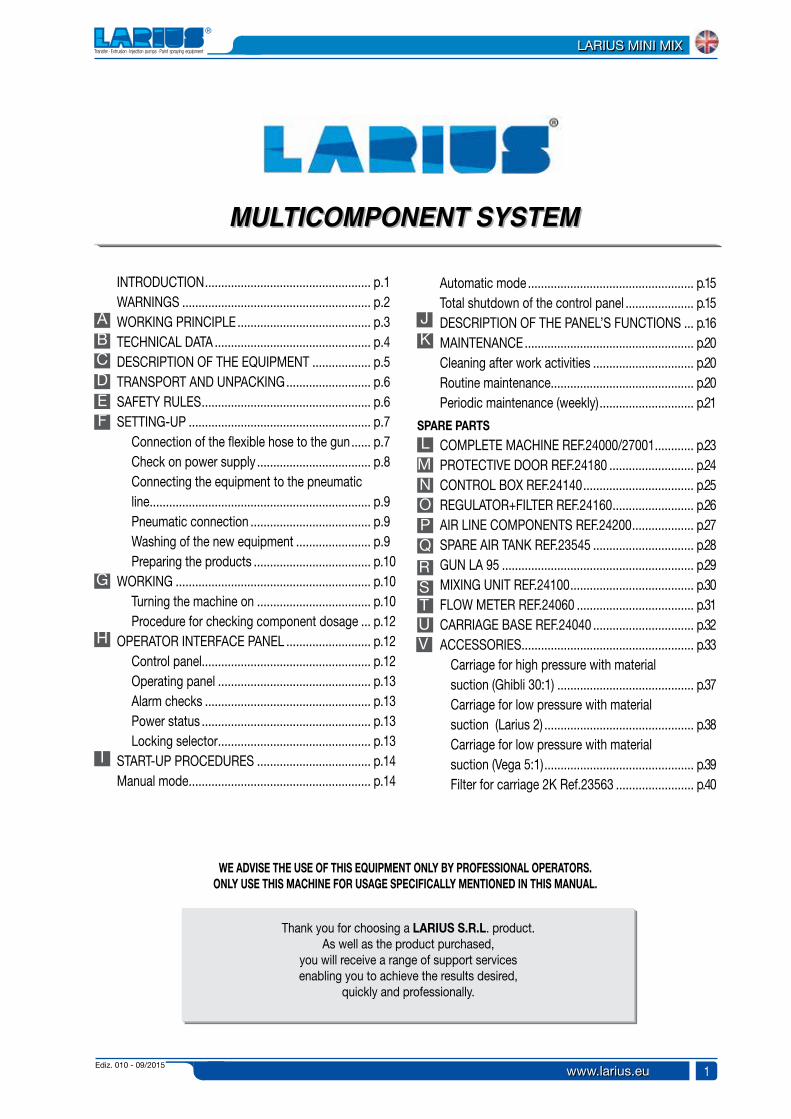
A WORKING PRINCIPLEThe LARIUS MINI-MIX is a bi-component mixing machine. It therefore provides for the dosage, mixture and application of bi-component products.This machine allows the user to work in low, medium or high pressure, with both airless or mist-less manual or automatic spray-guns.The dosing and the mixing of the components are regulated by an electronic control system.The hydraulic unit contains two flowmeters which regulate the input of the two components into the mixing lines. It is here, thanks to a static mixer, that the mixing of the products takes place.The machine is made up of 3 main units:
- The intake for the components- The hydraulic mixing unit- The command and control unit
ADVANTAGES OF USING THE LARIUS MINI-MIX- The possibility of using every methodology (low-medium-high
pressure / Mist-less / airless painting).- Increased product savings and consequent waste disposal
savings. - “Ecological” painting: performed in complete respect for the
working and external environment – Quick drying (even without a drying oven).
- High quality finish – Less use of paint thinners during cleaning phases.
- Increased resistance with respect to mono-component paints.
Sectors of use: Generic metalworking, Woodworking and Furnishings, Aerospace industry, Plastics, Bicycles and motorcycles, Automobile components, Automobiles, Painting of furniture, chairs, doors, Varnishing, Emulsion painting.
- The operator must possess and be familiar with the data sheets of the 2 components (A and B).
- The operator must be familiar with the characteristics of both the wash fluid to be used with the catalyser B, and the wash fluid to be used with the product A.
LARIUS srl SHALL BEAR NO RESPONSIBILITY FOR ANY EVENTUAL DAMAGES DERIVING FROM THE USE OF WASH FLUIDS INCOMPATIBLE WITH PRODUCTS A AND/OR B.
LARIUS srl SHALL BEAR NO RESPONSIBILITY FOR ACCIDENTS OR MALFUNCTIONS DERIVING FROM LACK OF FAMILIARITY WITH THE DATA SHEETS AND THE PRODUCTS UTILISED OR RESULTING FROM THE USE OF PRODUCTS WHICH ARE NOT COMPATIBLE WITH ONE ANOTHER.
ATENTION
- The catalyser and its relative circuit must never be cleaned with incompatible liquids.
- Make sure that: if the product to be used is water-based, the relative circuit within the machine is cleaned using water. If, on the other hand, the product to be used is solvent-based, the relative circuit must be cleaned using a solvent.
BEFORE USING THE LARIUS MIX 2K EQUIPMENT
Ediz. 010 - 09/2015www.larius.eu
LARIUS MINI MIX
4
B
A
C
B
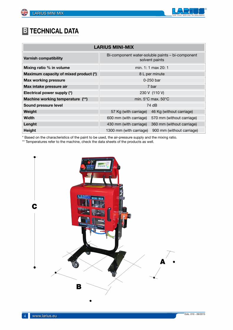
* Based on the characteristics of the paint to be used, the air-pressure supply and the mixing ratio.
TECHNICAL DATA
** Temperatures refer to the machine, check the data sheets of the products as well.
LARIUS MINI-MIX
Varnish compatibility
Mixing ratio % in volume
Maximum capacity of mixed product (*)
Max working pressure
Max intake pressure air
Electrical power supply (*)
Machine working temperature (**)
Sound pressure level
Weight
Width
Lenght
Height
Bi-component water-soluble paints – bi-component solvent paints
min. 1: 1 max 20: 1
8 L per minute
0-250 bar
7 bar
230 V (110 V)
min. 5°C max. 50°C
74 dB
57 Kg (with carriage) 46 Kg (without carriage)
600 mm (with carriage) 570 mm (without carriage)
430 mm (with carriage) 360 mm (without carriage)
1300 mm (with carriage) 900 mm (without carriage)

Ediz. 010 - 09/2015 www.larius.eu
LARIUS MINI MIX
5
4
3
5
1
6
2
C DESCRIPTION OF THE EQUIPMENT
POS.
123
Electronic management panelElectro-pneumatic unitVisual alarm device located on the control panel
Description POS. Description
456
0-250 bar mixing headAir pressure regulationRegulator filter
2
2
1
4
5

Ediz. 010 - 09/2015www.larius.eu
LARIUS MINI MIX
6
D TRANSPORT AND UNPACK-ING
• The packed parts should be handled as indicated in the symbols and markings on the outside of the packing.
• Before installing the equipment, ensure that the area to be used is large enough for such purposes, is properly lit and has a clean, smooth floor surface.
E SAFETY RULES• THE EMPLOYER SHALL TRAIN ITS EMPLOYEES ABOUT ALL
THOSE RISKS STEMMING FROM ACCIDENTS, ABOUT THE USE OF SAFETY DEVICES FOR THEIR OWN SAFETY AND ABOUT THE GENERAL RULES FOR ACCIDENT PREVENTION IN COMPLIANCE WITH INTERNATIONAL REGULATIONS AND WITH THE LAWS OF THE COUNTRY WHERE THE PLANT IS USED.
• THE BEHAVIOUR OF THE EMPLOYEES SHALL STRICTLY COMPLY WITH THE ACCIDENT PREVENTION AND ALSO ENVIRONMENTAL REGULATIONS IN FORCE IN THE COUNTRY WHERE THE PLANT IS INSTALLED AND USED.
The user is responsible for the operations of unloading and handling and should use the maximum care so as not to damage the individual parts or injure anyone.To perform the unloading operation, use only qualified and trained personnel (truck and crane operators, etc.) and also suitable hoisting equipment for the weight of the installation or its parts. Follow carefully all the safety rules. The personnel must be equipped with the necessary safety clothing.
• The manufacturer will not be responsible for the unloading operations and transport to the workplace of the machine.
• Check the packing is undamaged on receipt of the equipment. Unpack the machine and verify if there has been any damage due to transportation.
In case of damage, call immediately LARIUS and the Shipping Agent.
All the notices about possible damage or anomalies must arrive timely within 8 days at least from the date of receipt of the plant through Registered Letter to the Shipping Agent and to LARIUS.
The disposal of packaging materials is a customer’s competence and must be performed in accordance with the regulations in force in the country where the plant is installed and used. It is nevertheless sound practice to recycle packaging materials in an environment-friendly manner as much as possible.
• KEEP YOUR WORK PLACE CLEAN AND TIDY. DISORDER WHERE YOU ARE WORKING CREATES A POTENTIAL RISK OF ACCIDENTS.
• ALWAYS KEEP PROPER BALANCE AVOIDING UNUSUAL STANCE.
• BEFORE USING THE TOOL, ENSURE THERE ARE NOT DAMAGED PARTS AND THE MACHINE CAN WORK PROPERLY.
• ALWAYS FOLLOW THE INSTRUCTIONS ABOUT SAFETY AND THE REGULATIONS IN FORCE.
• KEEP THOSE WHO ARE NOT RESPONSIBLE FOR THE EQUIPMENT OUT OF THE WORK AREA..
• NEVER EXCEED THE MAXIMUM WORKING PRESSURE INDICATED.
• NEVER POINT THE SPRAY GUN AT YOURSELVES OR AT OTHER PEOPLE. THE CONTACT WITH THE CASTING CAN CAUSE SERIOUS INJURIES.
• IN CASE OF INJURIES CAUSED BY THE GUN CASTING, SEEK IMMEDIATE MEDICAL ADVICE SPECIFYING THE TYPE OF THE PRODUCT INJECTED. NEVER UNDERVALUE A WOUND CAUSED BY THE INJECTION OF A FLUID.
• ALWAYS DISCONNECT THE SUPPLY AND RELEASE THE PRESSURE IN THE CIRCUIT BEFORE PERFORMING ANY CHECK OR PART REPLACEMENT OF THE EQUIPMENT.
• NEVER MODIFY ANY PART IN THE EQUIPMENT. CHECK REGULARLY THE COMPONENTS OF THE SYSTEM.
REPLACE THE PARTS DAMAGED OR WORN.
• TIGHTEN AND CHECK ALL THE FITTINGS FOR CONNECTION
Read carefully and entirely the following instructions before using the product. Please save these instructions in a safe place.
The unauthorised tampering/replacement of one or more parts composing the machine, the use of accessories, tools, expendable materials other than those recommended by the manufacturer can be a danger of accident. The manufacturer will be relieved from tort and criminal liability.

Ediz. 010 - 09/2015 www.larius.eu
LARIUS MINI MIX
7
BETWEEN PUMP, FLEXIBLE HOSE AND SPRAY GUN BEFORE USING THE EQUIPMENT.
• ALWAYS USE THE FLEXIBLE HOSE SUPPLIED WITH STANDARD KIT. THE USE OF ANY ACCESSORIES OR TOOLING OTHER THAN THOSE RECOMMENDED IN THIS MANUAL, MAY CAUSE DAMAGE OR INJURE THE OPERATOR.
• THE FLUID CONTAINED IN THE FLEXIBLE HOSE CAN BE VERY
DANGEROUS. HANDLE THE FLEXIBLE HOSE CAREFULLY. DO NOT PULL THE FLEXIBLE HOSE TO MOVE THE EQUIPMENT. NEVER USE A DAMAGED OR A REPAIRED FLEXIBLE HOSE.
• NEVER SPRAY OVER FLAMMABLE PRODUCTS OR SOLVENTS IN CLOSED PLACES.
• NEVER USE THE TOOLING IN PRESENCE OF POTENTIALLY EXPLOSIVE GAS.
The high speed of travel of the product in the hose can create static electricity through discharges and sparks. It is suggested to earth the equipment.
Always check the product is compatible with the materials composing the equipment (pump, spray gun, flexible hose and accessories) with which it can come into contact. Never use paints or solvents containing halogen hydrocarbons (as the methylene chloride). If these products come into contact with aluminium parts can provoke dangerous chemical reactions with risk of corrosion and explosion.
IF THE PRODUCT TO BE USED IS TOXIC, AVOID INHALATION AND CONTACT BY USING PROTECTION GLOVES, GOGGLES AND PROPER FACE SHIELDS.
TAKE PROPER SAFETY MEASURES FOR THE PROTECTION OF HEARING IN CASE OF WORK NEAR THE PLANT.
• MAKE SURE YOU KNOW HOW TO SHUT OFF THE EQUIPMENT IF NECESSARY. INEXPERIENCED USERS SHOULD BE TRAINED TO SAFELY AND PROPERLY USE THE MACHINE BEFORE OPERATING IT.
• KEEP UNAUTHORISED PERSONNEL AWAY FROM THE MACHINE, ABOVE ALL IF A TOXIC PRODUCT IS BEING UTILISED.
• IF NECESSARY, USE WARNING SIGNS TO KEEP ANYONE
PRESENT AT A SAFE DISTANCE.
• MAKE SURE THAT THERE IS ALWAYS SOMEONE WITHIN SHOUTING DISTANCE IN CASE AN ACCIDENT SHOULD OCCUR.
F SETTING-UPCONNECTION OF THE FLEXIBLE HOSE TO THE GUN
Connect the 4 flexible tubes to the machine.• The three intake tubes are o be connected to the supply
pump: the component A tube (F3), the component B tube (F1) and the wash fluid tube (F2).
F1F2F1

Ediz. 010 - 09/2015www.larius.eu
LARIUS MINI MIX
8
CHECK ON POWER SUPPLY
Make sure that the system is properly grounded. Use an electrical plug which guarantees the proper grounding of the system.
DO NOT use thread pastes upon the connections.It is recommended to use the tubes which have been supplied along with the machine.NEVER use a damaged or repaired flexible tube.
The machine requires a 220V alternating current power supply.
LARIUS MINI-MIX equipment is fitted with an additional external earth cable that is connected to the stem on the pump unit be means of a specific clamp (F6), in order to protect the operator against any risk of static or electric shock.
Should anyone use an extension cable between the tooling and the socket, it must have the same characteristics as the cable supplied (minimum diameter of the wire 4 mm2) with a maximum length of 50 mt. Higher lengths and lower diameters can provoke excessive voltage falls and also an anomalous working of the equipment.
• The fourth tube (F4) is to be connected to the mixing tube’s outlet (F5) and connected to the spray-gun.
Make sure that the connections are tightly sealed. It is recommended to use two wrenches to tighten them.
F6
F4
F5
Ediz. 010 - 09/2015 www.larius.eu
LARIUS MINI MIX
9
To avoid electric shock when disassembling or checking the elec-tronic equipment, wait 5 minutes after having disconnected the power supply cable, so that the electricity stored in the condensers while working can be dissipated.
Also check the condition of the earth cable to avoid any risk of shock.
Before carrying out any checks on the machine (maintenance, cleaning, or replacing parts) switch off the machine and wait until it has stopped altogether.
While checking stay away from electrical or moving parts to avoid any risk of shock or crushing of hands.
WARNING :
• DO NOT modify the plug for the earth socket in any way.
• ONLY use electrical connections that are earthed.
• Make sure that any earth extension cords are in good condition.
• ONLY use three-core extension cables.
• Avoid direct contact with the rain. Keep the equipment in a dry place.
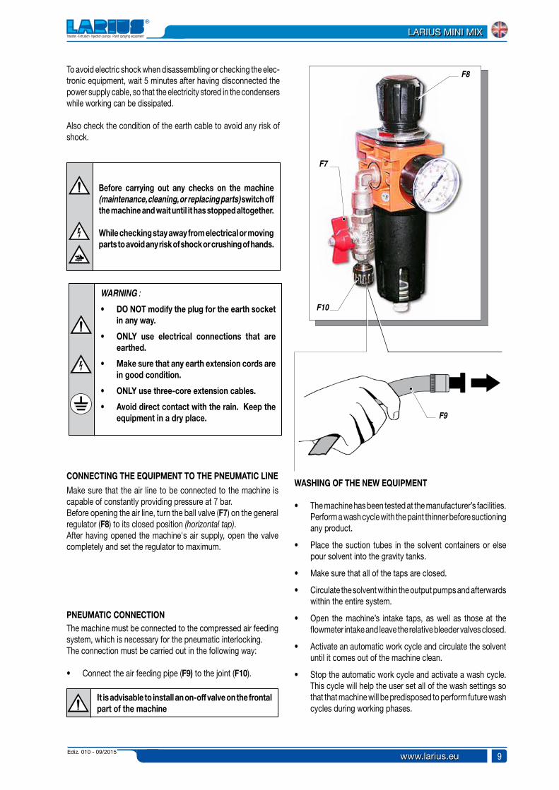
CONNECTING THE EQUIPMENT TO THE PNEUMATIC LINE
Make sure that the air line to be connected to the machine is capable of constantly providing pressure at 7 bar.Before opening the air line, turn the ball valve (F7) on the general regulator (F8) to its closed position (horizontal tap).After having opened the machine's air supply, open the valve completely and set the regulator to maximum.
WASHING OF THE NEW EQUIPMENT
• The machine has been tested at the manufacturer’s facilities. Perform a wash cycle with the paint thinner before suctioning any product.
• Place the suction tubes in the solvent containers or else pour solvent into the gravity tanks.
• Make sure that all of the taps are closed.
• Circulate the solvent within the output pumps and afterwards within the entire system.
• Open the machine’s intake taps, as well as those at the flowmeter intake and leave the relative bleeder valves closed.
• Activate an automatic work cycle and circulate the solvent until it comes out of the machine clean.
• Stop the automatic work cycle and activate a wash cycle. This cycle will help the user set all of the wash settings so that that machine will be predisposed to perform future wash cycles during working phases.
PNEUMATIC CONNECTIONThe machine must be connected to the compressed air feeding system, which is necessary for the pneumatic interlocking.The connection must be carried out in the following way:
• Connect the air feeding pipe (F9) to the joint (F10).
It is advisable to install an on-off valve on the frontal part of the machine
F7
F8
F9
F10

Ediz. 010 - 09/2015www.larius.eu
LARIUS MINI MIX
10
PREPARING THE PRODUCTS
Make sure the product to be used is compatible with the materials employed for manufacturing the equipment (stainless steel and aluminium). Because of that, please contact the supplier of the product.
In order to prepare the products (i.e. for dilution), refer to the supplier’s data sheets.
WORKING
TURNING THE MACHINE ONConnect the machine up to the current and then to the air line (supply at 7bar). Turn the machine on by pressing the switch (G1) on th side of the control box, setting it to ON.
G
After having loaded the two supply pumps, make sure that the components are flowing, in their relative lines, up to the mixing block.Use the manual valves (G2) located beneath the flowmeters (bleeder valves) to verify whether the components are present.
• During the wash cycle, hold the spray-gun (F11) over a container (F12) and keep the trigger pulled.
Absolutely avoid to spray solvents indoors.
For disposing of the washing liquid, see the requirements laid down in the Standards in force in the country in which the equipment is used and act accordingly. The Client is solely responsible for any irregular action taken before, during, or after disposing of washing liquid, or in interpreting and applying the current Standards in this regard.
• Now the machine is ready. When water-based paint has been used, in addition to washing using the cleaning liquid, we recommend washing with soapy water and then clean water.
This operation allows for the elimination of any eventual air bubbles within the circuit.
If it is the first time the machine is used, wash. The machines are tested and there may be some oil residues remaining within.
G2
F11
F12
G2
G1
ON
Ediz. 010 - 09/2015 www.larius.eu
LARIUS MINI MIX
11
MAN / AUT
500-700 mm
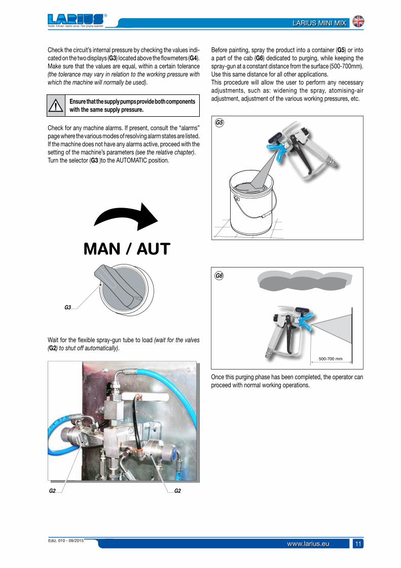
Check the circuit’s internal pressure by checking the values indi-cated on the two displays (G3) located above the flowmeters (G4). Make sure that the values are equal, within a certain tolerance (the tolerance may vary in relation to the working pressure with which the machine will normally be used).
Wait for the flexible spray-gun tube to load (wait for the valves (G2) to shut off automatically).
Before painting, spray the product into a container (G5) or into a part of the cab (G6) dedicated to purging, while keeping the spray-gun at a constant distance from the surface (500-700mm). Use this same distance for all other applications.This procedure will allow the user to perform any necessary adjustments, such as: widening the spray, atomising-air adjustment, adjustment of the various working pressures, etc.
Once this purging phase has been completed, the operator can proceed with normal working operations.
Ensure that the supply pumps provide both components with the same supply pressure.
Check for any machine alarms. If present, consult the “alarms” page where the various modes of resolving alarm states are listed.If the machine does not have any alarms active, proceed with the setting of the machine’s parameters (see the relative chapter).Turn the selector (G3 )to the AUTOMATIC position.
G2 G2
G3
G5
G6
Ediz. 010 - 09/2015www.larius.eu
LARIUS MINI MIX
12
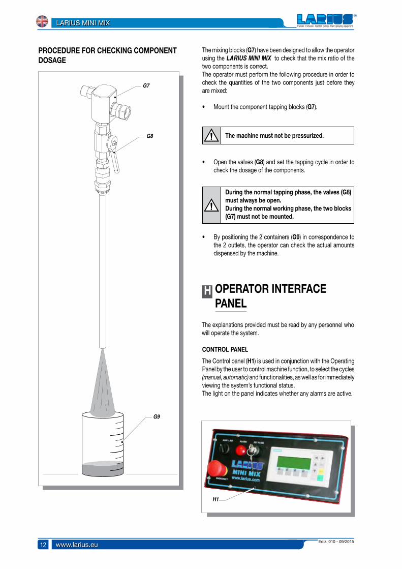
H OPERATOR INTERFACE PANEL
The explanations provided must be read by any personnel who will operate the system.
CONTROL PANEL
The Control panel (H1) is used in conjunction with the Operating Panel by the user to control machine function, to select the cycles (manual, automatic) and functionalities, as well as for immediately viewing the system’s functional status.The light on the panel indicates whether any alarms are active.
PROCEDURE FOR CHECKING COMPONENT DOSAGE
The mixing blocks (G7) have been designed to allow the operator using the LARIUS MINI MIX to check that the mix ratio of the two components is correct.The operator must perform the following procedure in order to check the quantities of the two components just before they are mixed:
• Mount the component tapping blocks (G7).
• Open the valves (G8) and set the tapping cycle in order to check the dosage of the components.
The machine must not be pressurized.
• By positioning the 2 containers (G9) in correspondence to the 2 outlets, the operator can check the actual amounts dispensed by the machine.
During the normal tapping phase, the valves (G8) must always be open.During the normal working phase, the two blocks (G7) must not be mounted.
H1
G7
G8
G9
Ediz. 010 - 09/2015 www.larius.eu
LARIUS MINI MIX
13
TAB
+ / -TAB
+ / -
INSDEL
ENTER
ENTER
OPERATING PANEL
The operating panel is connected to the system and is used for:
- inserting and viewing process variables;- viewing alarms and signals in order for the operator to easily
identify them while the system is in function;- selecting the desired function in manual mode.
ALARM CHECKS
The PLC reacts in the following manner to every alarm event:
- The red light (H2) installed upon the control panel flashes;
- The operating panel displays the text which corresponds to the alarm.
The system will not allow an alarm to be reset if the situation which caused the alarm has not been resolved.Some alarms are automatically reset once the situation which caused the alarm has been resolved.
If the system functions in a different manner with respect to the information which has been inserted, the user is advised to communicate the event to the manufacturer so that a technician may verify the program which has been loaded onto the PLC.
To access the various items to be set, carry out the operations listed and explained in this manual.
In order to alter the machine settings, the switch must be posi-tioned correctly, using the key. If not, any data altered will return to the previous settings when confirming the change.
POWER STATUS
The power status is indicated by a green light located on the system’s ON/OFF selector.
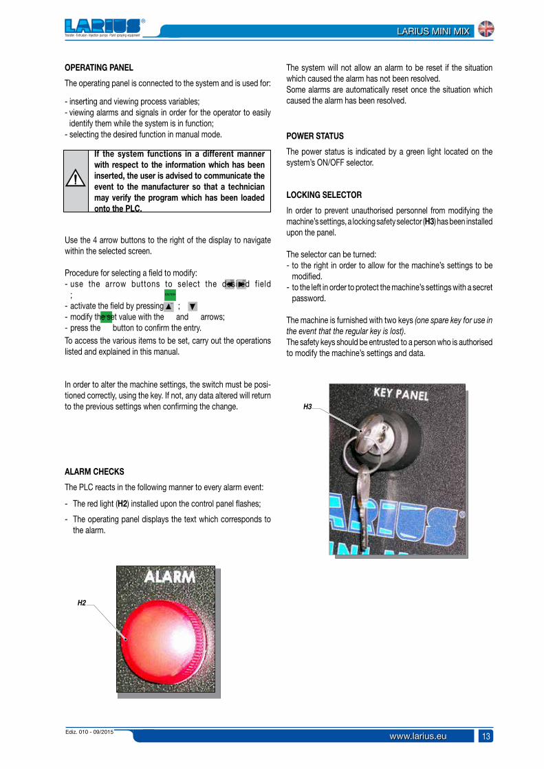
LOCKING SELECTOR
In order to prevent unauthorised personnel from modifying the machine’s settings, a locking safety selector (H3) has been installed upon the panel.
The selector can be turned:- to the right in order to allow for the machine’s settings to be
modified.- to the left in order to protect the machine’s settings with a secret
password.
The machine is furnished with two keys (one spare key for use in the event that the regular key is lost).The safety keys should be entrusted to a person who is authorised to modify the machine’s settings and data.
Use the 4 arrow buttons to the right of the display to navigate within the selected screen.
Procedure for selecting a field to modify:- use the arrow buttons to select the desired field
; - activate the field by pressing ; - modify the set value with the and arrows;- press the button to confirm the entry.
H2
H3
Ediz. 010 - 09/2015www.larius.eu
LARIUS MINI MIX
14
MAN / AUTMAN / AUT
MAN / AUTMAN / AUT
MAN / AUTMAN / AUT
SIEMENS
HELP
ESC
ACK
ENTERSHIFT
TAB
INSDEL
+ / -
SIMATIC PANEL
F3 F4F2F1
LavaggioManuali: Ev A 0 Ev B 0
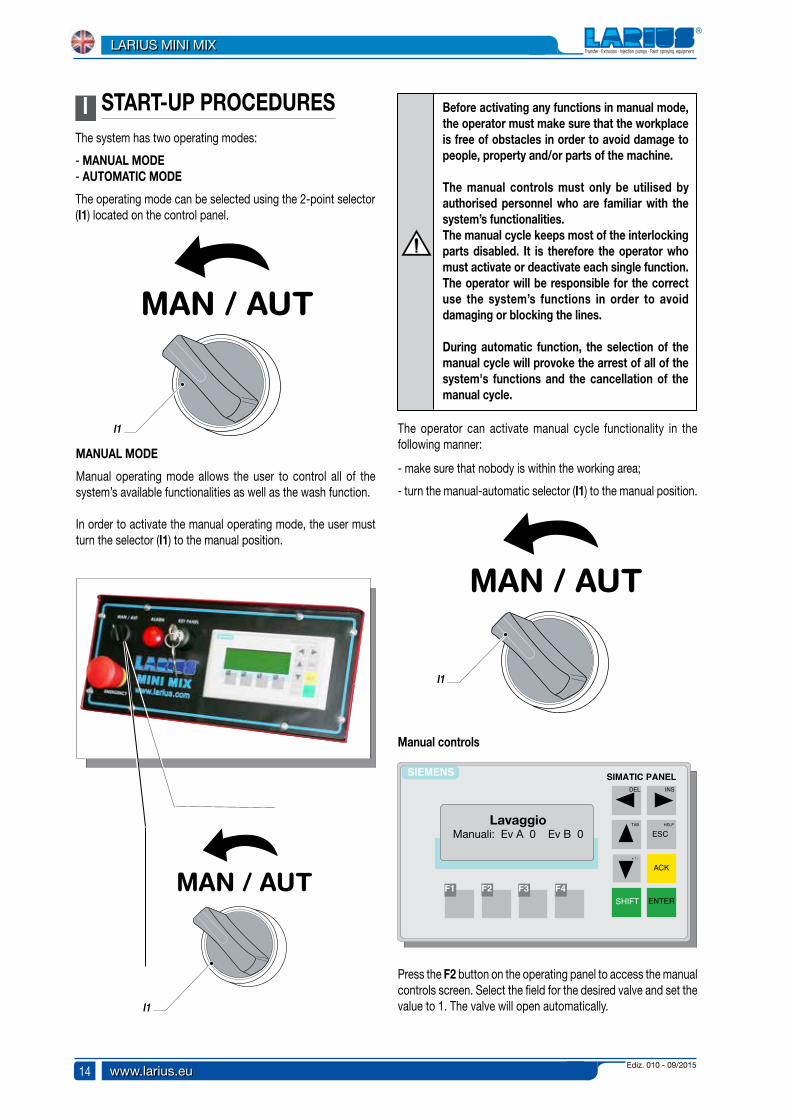
I START-UP PROCEDURESThe system has two operating modes:
- MANUAL MODE - AUTOMATIC MODE
The operating mode can be selected using the 2-point selector (I1) located on the control panel.
MANUAL MODE
Manual operating mode allows the user to control all of the system’s available functionalities as well as the wash function.
In order to activate the manual operating mode, the user must turn the selector (I1) to the manual position.
Before activating any functions in manual mode, the operator must make sure that the workplace is free of obstacles in order to avoid damage to people, property and/or parts of the machine.
The manual controls must only be utilised by authorised personnel who are familiar with the system’s functionalities.The manual cycle keeps most of the interlocking parts disabled. It is therefore the operator who must activate or deactivate each single function.The operator will be responsible for the correct use the system’s functions in order to avoid damaging or blocking the lines.
During automatic function, the selection of the manual cycle will provoke the arrest of all of the system's functions and the cancellation of the manual cycle.
The operator can activate manual cycle functionality in the following manner:
- make sure that nobody is within the working area;
- turn the manual-automatic selector (I1) to the manual position.
Manual controls
Press the F2 button on the operating panel to access the manual controls screen. Select the field for the desired valve and set the value to 1. The valve will open automatically.I1
I1
I1

Ediz. 010 - 09/2015 www.larius.eu
LARIUS MINI MIX
15
MAN / AUTMAN / AUT
MAN / AUT
SIEMENS
HELP
ESC
ACK
ENTERSHIFT
TAB
INSDEL
+ / -
SIMATIC PANEL
F3 F4F2F1
The valves are defined as follows:
- Ev A: component A electrovalve- Ev B: component B electrovalve
These four fields can be used to switch over/open every single electrovalve while the selector (I1) is set to MAN.
Modify the field’s value to 0 or 1 in order to activate or deactivate the relative electrovalve and to allow the selected component to flow within the machine.
This function is necessary for performing a complete wash of the entire system when the two pumps have to be washed using two different wash fluids (i.e. component A requires water to be used as a wash fluid and the catalyser B requires the use of a solvent).
This operation (manual valve opening), must also be carried out when discharging pressures. When a valve is opened in the absence of product, the pressure contained within the mixing block is released.Carry out the operation for component A and component B (Ev A, Ev B).
AUTOMATIC MODE
The automatic cycle is used for regular working functionality.
In order to activate automatic mode functionality, the operator must turn the selector (I1) to the automatic position.To deactivate automatic mode functionality, just turn the selector (I1) to the manual position.
When the automatic cycle is active, the program controls the sequence of the valves for the two components and doses them based on the requested ratio and based on the “impulse count frequency” settings.Access the “General Settings” screen.
The “impulse count frequency" setting affects the frequency of the valve sequence.
Example: Let us suppose we are selecting a volume ratio of 3/1 (3 parts A and 1 part B) and setting a pulse frequency of 1. The programme will control the valve opening, counting 30 pulses of the A supply measurer and 10 pulses of the B supply measurer.If a pulse frequency of 2 were set, the machine would count 60 pulses of A and 20 pulses of B.
The adjustment of the “impulse count frequency” must be done in such a way so as to avoid high frequencies which may not be supported by the components.
TOTAL SHUTDOWN OF THE CONTROL PANEL
The system shutdown procedure requires the main switch (I2) to be turned to the OFF position.This operation completely arrests all of the system’s functionalities.
Impostazioni generali Frequenza impulsi conteggio 000Rapporto A/B 00 /00
I2
OFF
I1
I1
Ediz. 010 - 09/2015www.larius.eu
LARIUS MINI MIX
16
SIEMENS
HELP
ESC
ACK
ENTERSHIFT
TAB
INSDEL
+ / -
SIMATIC PANEL
F3 F4F2F1
SIEMENS
HELP
ESC
ACK
ENTERSHIFT
TAB
INSDEL
+ / -
SIMATIC PANEL
F3 F4F2F1
F1
SIEMENS
HELP
ESC
ACK
ENTERSHIFT
TAB
INSDEL
+ / -
SIMATIC PANEL
F3 F4F2F1
J DESCRIPTION OF THE PANEL’S FUNCTIONS
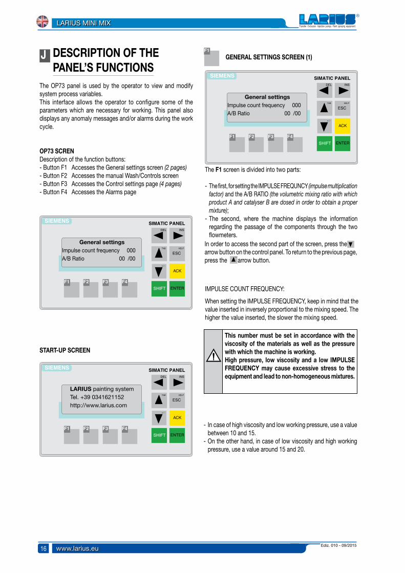
The OP73 panel is used by the operator to view and modify system process variables.This interface allows the operator to configure some of the parameters which are necessary for working. This panel also displays any anomaly messages and/or alarms during the work cycle.
OP73 SCRENDescription of the function buttons:- Button F1 Accesses the General settings screen (2 pages)- Button F2 Accesses the manual Wash/Controls screen- Button F3 Accesses the Control settings page (4 pages)- Button F4 Accesses the Alarms page
START-UP SCREEN
LARIUS painting system Tel. +39 0341621152 http://www.larius.com
General settings Impulse count frequency 000A/B Ratio 00 /00
GENERAL SETTINGS SCREEN (1)
The F1 screen is divided into two parts: - The first, for setting the IMPULSE FREQUNCY (impulse multiplication
factor) and the A/B RATIO (the volumetric mixing ratio with which product A and catalyser B are dosed in order to obtain a proper mixture);
- The second, where the machine displays the information regarding the passage of the components through the two flowmeters.
IMPULSE COUNT FREQUENCY:
When setting the IMPULSE FREQUENCY, keep in mind that the value inserted in inversely proportional to the mixing speed. The higher the value inserted, the slower the mixing speed.
General settings Impulse count frequency 000A/B Ratio 00 /00
This number must be set in accordance with the viscosity of the materials as well as the pressure with which the machine is working.High pressure, low viscosity and a low IMPULSE FREQUENCY may cause excessive stress to the equipment and lead to non-homogeneous mixtures.
- In case of high viscosity and low working pressure, use a value between 10 and 15.
- On the other hand, in case of low viscosity and high working pressure, use a value around 15 and 20.
TAB
+ / -
TAB
+ / -
In order to access the second part of the screen, press the arrow button on the control panel. To return to the previous page, press the arrow button.
Ediz. 010 - 09/2015 www.larius.eu
LARIUS MINI MIX
17
SIEMENS
HELP
ESC
ACK
ENTERSHIFT
TAB
INSDEL
+ / -
SIMATIC PANEL
F3 F4F2F1
Impulses to count A 000Actual count A 000Impulses to count B 000Actual count B 000
SIEMENS
HELP
ESC
ACK
ENTERSHIFT
TAB
INSDEL
+ / -
SIMATIC PANEL
F3 F4F2F1
SIEMENS
HELP
ESC
ACK
ENTERSHIFT
TAB
INSDEL
+ / -
SIMATIC PANEL
F3 F4F2F1
Control settingsPot life (min) 00% ratio error
MANUALManual: Ev A 0 Ev B 0
F2
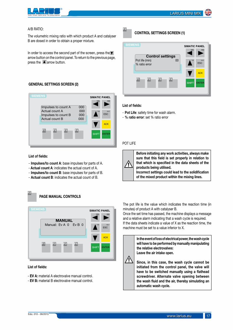
F3A/B RATIO:
The volumetric mixing ratio with which product A and catalyser B are dosed in order to obtain a proper mixture.
GENERAL SETTINGS SCREEN (2)
List of fields:
- Impulses/to count A: base impulses for parts of A.- Actual count A: indicates the actual count of A.- Impulses/to count B: base impulses for parts of B.- Actual count B: indicates the actual count of B.
PAGE MANUAL CONTROLS
List of fields:
- EV A: material A electrovalve manual control.- EV B: material B electrovalve manual control.
List of fields:
- Pot Life: safety time for wash alarm.- % ratio error: set % ratio error
CONTROL SETTINGS SCREEN (1)
POT LIFE
Before initiating any work activities, always make sure that this field is set properly in relation to that which is specified in the data sheets of the products being utilised.Incorrect settings could lead to the solidification of the mixed product within the mixing lines.
The pot life is the value which indicates the reaction time (in minutes) of product A with catalyser B.Once the set time has passed, the machine displays a message and a relative alarm indicating that a wash cycle is required.If the data sheets indicate a value of X as the reaction time, the machine must be set to a value inferior to X.
In the event of loss of electrical power, the wash cycle will have to be performed by manually manipulating the relative electrovalves:Leave the air intake open. Since, in this case, the wash cycle cannot be initiated from the control panel, the valve will have to be switched manually using a flathead screwdriver. Alternate valve opening between the wash fluid and the air, thereby simulating an automatic wash cycle.
TAB
+ / -
TAB
+ / -
In order to access the second part of the screen, press the arrow button on the control panel. To return to the previous page, press the arrow button.
Ediz. 010 - 09/2015www.larius.eu
LARIUS MINI MIX
18
SIEMENS
HELP
ESC
ACK
ENTERSHIFT
TAB
INSDEL
+ / -
SIMATIC PANEL
F3 F4F2F1
Ratio control 0 Min. Last Max.00.000 00.000 00.000
SIEMENS
HELP
ESC
ACK
ENTERSHIFT
TAB
INSDEL
+ / -
SIMATIC PANEL
F3 F4F2F1
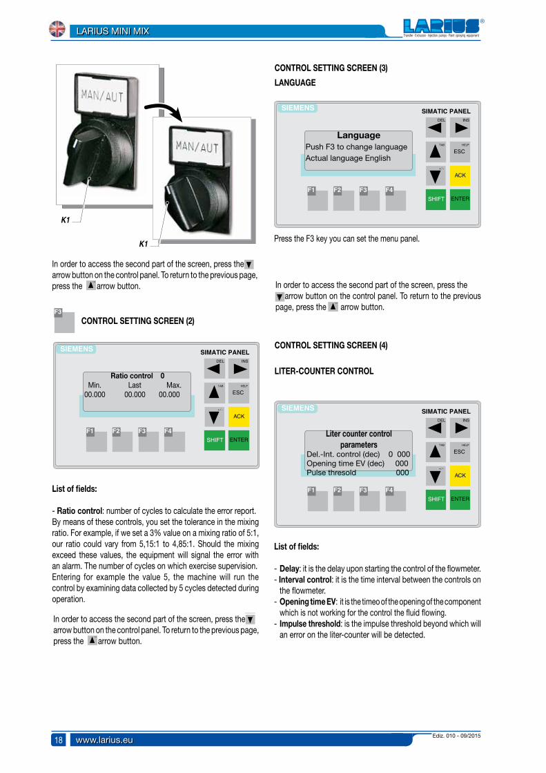
LanguagePush F3 to change languageActual language English
SIEMENS
HELP
ESC
ACK
ENTERSHIFT
TAB
INSDEL
+ / -
SIMATIC PANEL
F3 F4F2F1
Liter counter control parameters
Del.-Int. control (dec) 0 000Opening time EV (dec) 000Pulse thresold 000
F3
List of fields:
- Ratio control: number of cycles to calculate the error report. By means of these controls, you set the tolerance in the mixing ratio. For example, if we set a 3% value on a mixing ratio of 5:1, our ratio could vary from 5,15:1 to 4,85:1. Should the mixing exceed these values, the equipment will signal the error with an alarm. The number of cycles on which exercise supervision.Entering for example the value 5, the machine will run the control by examining data collected by 5 cycles detected during operation.
CONTROL SETTING SCREEN (2)
LANGUAGE
Press the F3 key you can set the menu panel.
LITER-COUNTER CONTROL
List of fields:
- Delay: it is the delay upon starting the control of the flowmeter.- Interval control: it is the time interval between the controls on
the flowmeter.- Opening time EV: it is the timeo of the opening of the component
which is not working for the control the fluid flowing.- Impulse threshold: is the impulse threshold beyond which will
an error on the liter-counter will be detected.
TAB
+ / -
TAB
+ / -
In order to access the second part of the screen, press the arrow button on the control panel. To return to the previous page, press the arrow button.
TAB
+ / -
TAB
+ / -
In order to access the second part of the screen, press the arrow button on the control panel. To return to the previous page, press the arrow button.
TAB
+ / -
TAB
+ / -
In order to access the second part of the screen, press the arrow button on the control panel. To return to the previous page, press the arrow button.
CONTROL SETTING SCREEN (3)
CONTROL SETTING SCREEN (4)
K1
K1

Ediz. 010 - 09/2015 www.larius.eu
LARIUS MINI MIX
19
SIEMENS
HELP
ESC
ACK
ENTERSHIFT
TAB
INSDEL
+ / -
SIMATIC PANEL
F3 F4F2F1
ALARMS Notice text ... notice
text .... notice
SIEMENS
HELP
ESC
ACK
ENTERSHIFT
TAB
INSDEL
+ / -
SIMATIC PANEL
F3 F4F2F1
ALARMSAlarm time POT LIFE
SIEMENS
HELP
ESC
ACK
ENTERSHIFT
TAB
INSDEL
+ / -
SIMATIC PANEL
F3 F4F2F1
ALARMS Alarm material out of ratio
SIEMENS
HELP
ESC
ACK
ENTERSHIFT
TAB
INSDEL
+ / -
SIMATIC PANEL
F3 F4F2F1
ALARMSAlarm liter-counter A
SIEMENS
HELP
ESC
ACK
ENTERSHIFT
TAB
INSDEL
+ / -
SIMATIC PANEL
F3 F4F2F1
ALARMS Alarm liter-counter B
ALARMS PAGE
- Emergency system alarm: it means that the mushroom emergency push button on the control panel is pressed.
Reset: Remove the mushroom emergency button and press F4. Silencing text: automatically by pressing F4.
- Alarm washing not performed: shows that washing had not been completed before power failure.
Reset: run the washing or press the emergency button if washing is not required and press F4.Silencing text: automatically by pressing F4.
SIEMENS
HELP
ESC
ACK
ENTERSHIFT
TAB
INSDEL
+ / -
SIMATIC PANEL
F3 F4F2F1
ALARMSAlarm washing not performed
- Alarm time POT LIFE: Indicates that washing has not been done before the pot life time.
Reset: run the washing or spray and press F4. Silencing text: automatically by pressing F4. F4
- Alarm out material ratio: Indicates that the ratio has exceeded the set range of cycles number.
Reset: press the F4.Silencing text: automatically by pressing F4.
- Alarm liter-counter A: indicates that the liter-counter A is not counting correctly.
Reset: press F4.Silencing text: automatically by pressing F4.
- Alarm liter-counter B: indicates that the liter-counter B is not counting correctly.
- Reset: press the F4.- Silencing text: automatically by pressing F4.
F4
Ediz. 010 - 09/2015www.larius.eu
LARIUS MINI MIX
20
MAN / AUTMAN / AUT
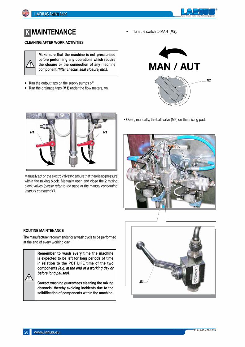
K MAINTENANCECLEANING AFTER WORK ACTIVITIES
Make sure that the machine is not pressurised before performing any operations which require the closure or the connection of any machine component (filter checks, seal closure, etc.).
• Turn the output taps on the supply pumps off.• Turn the drainage taps (M1) under the flow meters, on.
Manually act on the electro valves to ensure that there is no pressure within the mixing block. Manually open and close the 2 mixing block valves (please refer to the page of the manual concerning 'manual commands').
ROUTINE MAINTENANCE
The manufacturer recommends for a wash cycle to be performed at the end of every working day.
Remember to wash every time the machine is expected to be left for long periods of time in relation to the POT LIFE time of the two components (e.g. at the end of a working day or before long pauses).
Correct washing guarantees cleaning the mixing channels, thereby avoiding incidents due to the solidification of components within the machine.
• Turn the switch to MAN (M2).
• Open, manually, the ball valve (M3) on the mixing pad.
M1 M1
M2
M3
Ediz. 010 - 09/2015 www.larius.eu
LARIUS MINI MIX
21
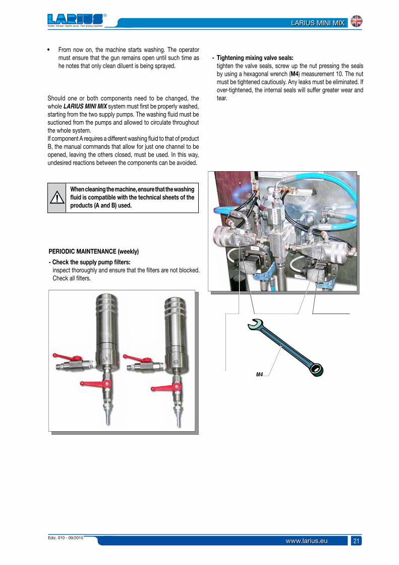
• From now on, the machine starts washing. The operator must ensure that the gun remains open until such time as he notes that only clean diluent is being sprayed.
Should one or both components need to be changed, the whole LARIUS MINI MIX system must first be properly washed, starting from the two supply pumps. The washing fluid must be suctioned from the pumps and allowed to circulate throughout the whole system.If component A requires a different washing fluid to that of product B, the manual commands that allow for just one channel to be opened, leaving the others closed, must be used. In this way, undesired reactions between the components can be avoided.
When cleaning the machine, ensure that the washing fluid is compatible with the technical sheets of the products (A and B) used.
PERIODIC MAINTENANCE (weekly)
- Check the supply pump filters: inspect thoroughly and ensure that the filters are not blocked. Check all filters.
- Tightening mixing valve seals: tighten the valve seals, screw up the nut pressing the seals
by using a hexagonal wrench (M4) measurement 10. The nut must be tightened cautiously. Any leaks must be eliminated. If over-tightened, the internal seals will suffer greater wear and tear.
M4
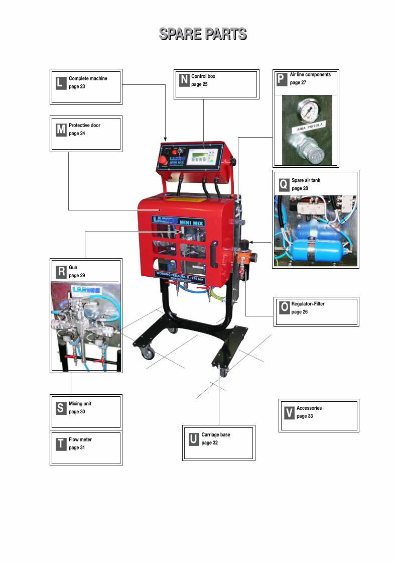
SPARE PARTSSPARE PARTS
OM Protective door
page 24
OQ Spare air tank
page 28
OL Complete machine
page 23ON Control box
page 25
OO Regulator+Filter
page 26
OR Gun
page 29
OS Mixing unit
page 30
OT Flow meter
page 31OU Carriage base
page 32
VAccessories
page 33
OP Air line components
page 27
Ediz. 010 - 09/2015 www.larius.eu
LARIUS MINI MIX
23
1
2
33
6
4
8
9
10
10
5
7
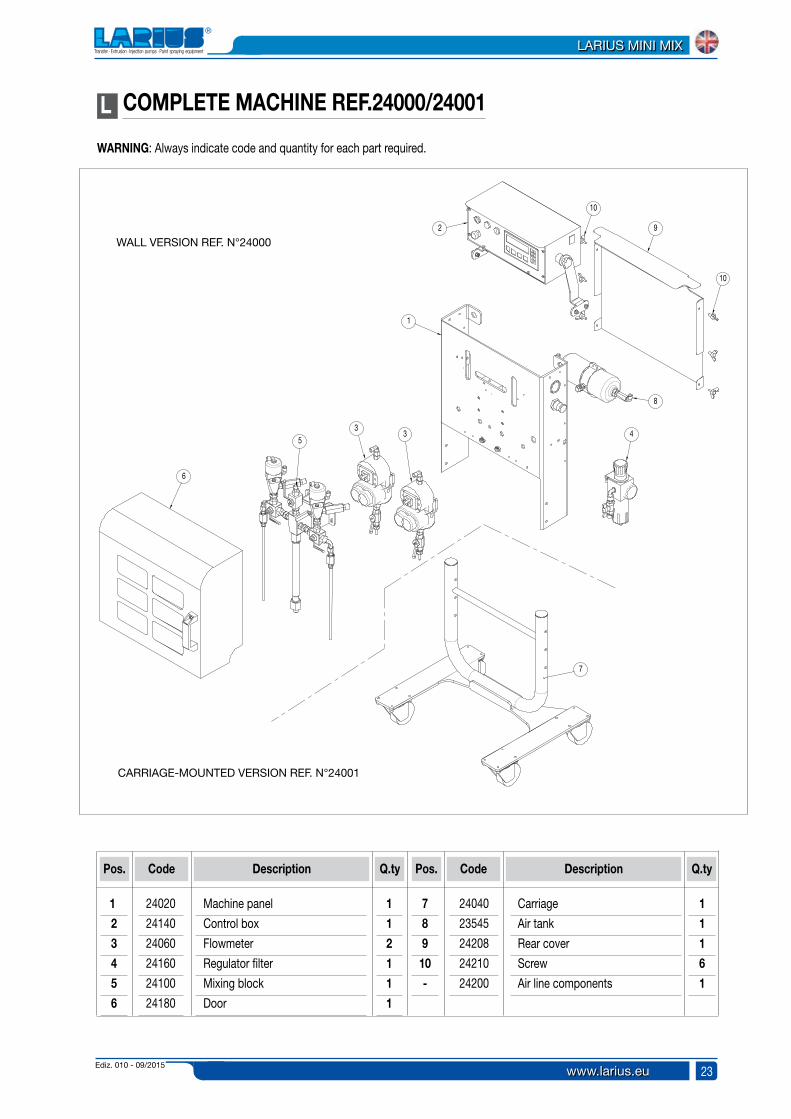
L COMPLETE MACHINE REF.24000/24001
Pos.
Machine panel
Control box
Flowmeter
Regulator filter
Mixing block
Door
Code Description
1.
2
3
4
5
6
Q.ty
1
1
2
1
1
1
Pos. Code Description Q.ty
7
8
9
10
-
Carriage
Air tank
Rear cover
Screw
Air line components
1
1
1
6
1
24020
24140
24060
24160
24100
24180
24040
23545
24208
24210
24200
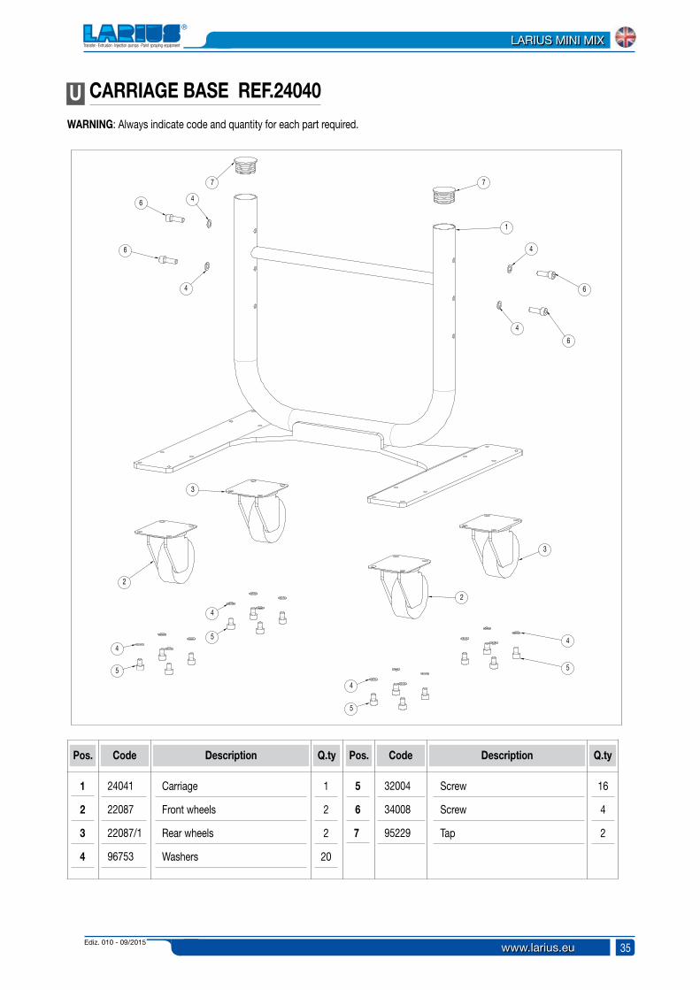
WARNING: Always indicate code and quantity for each part required.
WALL VERSION REF. N°24000
CARRIAGE-MOUNTED VERSION REF. N°24001

Ediz. 010 - 09/2015www.larius.eu
LARIUS MINI MIX
24
1
2
3
4
5
6
7
8
9
3
10
9 3 1014
12
11
13
M PROTECTIVE DOOR REF.24180WARNING: Always indicate code and quantity for each part required.
Pos.
Protective doorPannelWashersSelf-tightening nutHandleScrewWashersSelf-tightening nut
Code Description
1.2345678
Q.ty
111241222
Pos. Code Description Q.ty
91011121314-
HingeScrewWarning labelTop labelBottom labelHinge spacerMagnet
2811111
24181241829506380423200332004320243637
2418361362418524186241842420723212

Ediz. 010 - 09/2015 www.larius.eu
LARIUS MINI MIX
25
2
7
3
3
4 4
4 4
5
5
6
6
1
N CONTROL BOX REF.24140
Pos.
Control box
RH side for control box
Screw
Washers
Code Description
1
2
3
4
Q.ty
1
1
4
8
Pos. Code Description Q.ty
5
6
7
Self-tightening nut
Knob
LH side for control box
4
2
1
24141
24142
91062
91063
8042
4255
24142/1
WARNING: Always indicate code and quantity for each part required.
Ediz. 010 - 09/2015www.larius.eu
LARIUS MINI MIX
26
1
2
3
4
5
6
7
8
9
10
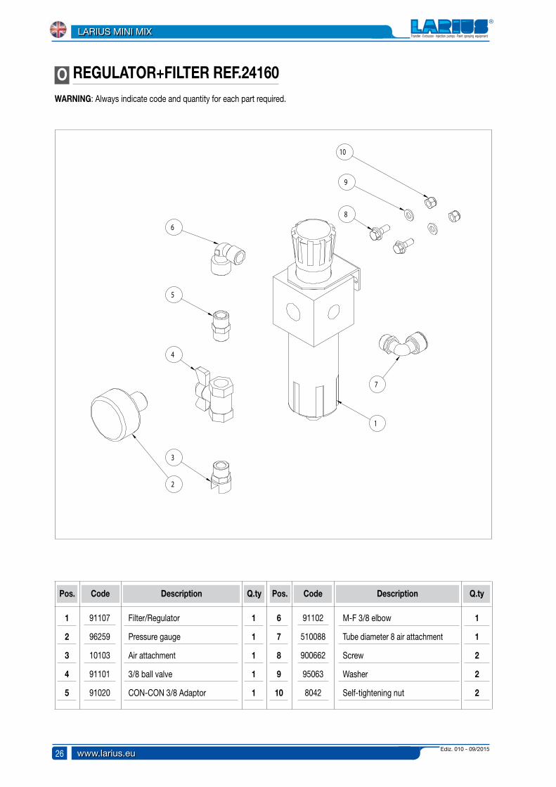
O REGULATOR+FILTER REF.24160
Pos.
Filter/Regulator
Pressure gauge
Air attachment
3/8 ball valve
CON-CON 3/8 Adaptor
Code Description
1
2
3
4
5
Q.ty
1
1
1
1
1
Pos. Code Description Q.ty
6
7
8
9
10
M-F 3/8 elbow
Tube diameter 8 air attachment
Screw
Washer
Self-tightening nut
1
1
2
2
2
91107
96259
10103
91101
91020
91102
510088
900662
95063
8042
WARNING: Always indicate code and quantity for each part required.

Ediz. 010 - 09/2015 www.larius.eu
LARIUS MINI MIX
27
N° PZ.23308 123309 1
3
34
5
9
10
4
3
1
2
3
3
8
7
11
6
PARTICULAR FOR N°1 ELECTROVALVE 23304
DENOMINATIONS
CONNECTORCOIL
P AIR LINE COMPONENTS REF.24200WARNING: Always indicate code and quantity for each part required.
Pos.
Air regulator
1/4 tube diameter 4 elbow
1/4 tube diameter 8 elbow
Electrovalve silencer
Electrovalve
Passage
Code Description
1
2
3
4
5
6
Q.ty
1
1
8
4
2
2
Pos. Code Description Q.ty
7
8
9
10
11
1/4 tube diameter 4 attachment
Pressure gauge
Washer
Screw
T-connector 3/8
1
1
4
4
2
3344
22014
8063
8074
23304
19176
19162
5341
5339
23306
510020
Ediz. 010 - 09/2015www.larius.eu
LARIUS MINI MIX
28
1
6
5
2
2
1
4
3
7
8
8
9
10
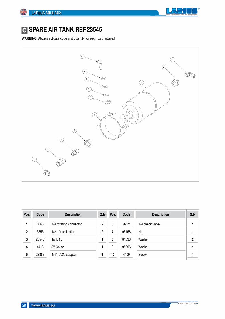
Q SPARE AIR TANK REF.23545WARNING: Always indicate code and quantity for each part required.
Pos.
1/4 rotating connector
1/2-1/4 reduction
Tank 1L
3'' Collar
1/4'' CON adapter
Code Description
1
2
3
4
5
Q.ty
2
2
1
1
1
Pos. Code Description Q.ty
6
7
8
9
10
1/4 check valve
Nut
Washer
Washer
Screw
1
1
2
1
1
8063
5356
23546
4413
23383
9902
95158
81033
95096
4409
Ediz. 010 - 09/2015 www.larius.eu
LARIUS MINI MIX
29
Whi
te p
age
inte
ntio
nary
Ediz. 010 - 09/2015www.larius.eu
LARIUS MINI MIX
30
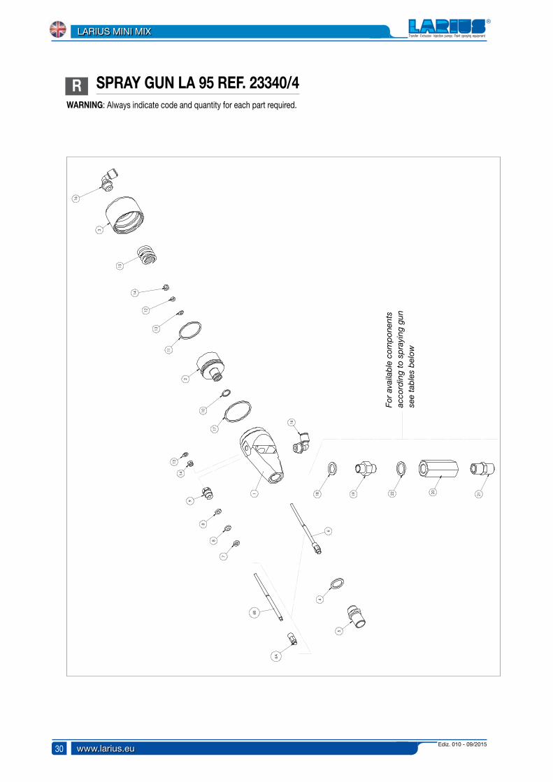
R SPRAY GUN LA 95 REF. 23340/4WARNING: Always indicate code and quantity for each part required.
1
2
5
7
15
11
10
17
22
12
20 21
For
avai
lab
le c
omp
onen
ts
acco
rdin
g to
sp
rayi
ng g
un
see
tab
les
bel
ow
Ediz. 010 - 09/2015 www.larius.eu
LARIUS MINI MIX
31
Pos.
1819202122
11111
330122202223412614933010
Code Description Q.ty
1/4 Gasket1/4-3/8 CIL-CIL AdapterCheck valve3/8-3/8 CON-CIL Adapter3/8 Gasket
Components for material A/B gun on Larius Mix 2K Ref.23340/1
Pos.
1819
11
330123103
Code Description Q.ty
1/4 Gasket
1/4-1/4 CIL-CIL Adapter
Components for wash gun on Larius Mix 2K Ref. 23340/2
Pos.
18/22192021
2211
330123103234033110
Code Description Q.ty
1/4 Gasket
1/4-1/4 CIL-CIL AdapterCheck valve
1/4-1/4 CON-CIL Adapter
Components for material A/B gun on Larius Mini Mix Ref.23340/3
Pos. Code Description Q.ty
HousingPistonRear spray gun stopperGasketSleeve completeRod completeTipRodRingGasketSeal holder screwOR 2043OR 3131NutBall Ø 4Self-tightening nutSpring1/4” rotating elbowOR 3162
1234 56
6A6B7,891011121314151617
1111111112111112121
2334123342/123343330072333623330233442333211712/111114/123335233382333951145339404311814806323348
Spray gun ref. 23340/4
Rep.
56
6A
Changes made to the gun with reference 23340/5 with basic double-effect valve LA95 and with 3/8” sleeve. Ball and ball housing increased.
Sleeve completeRod completeTip with 5/16" ball
Code Description Q.té
111
233642336323345
Rep.
56
6A
Changes made to the gun with reference 23340/6 with basic double-effect dosing valve LA95 and with flared 3/8” sleeve. Ball and ball housing increased.
Sleeve completeRod completeTip with 5/16" ball
Code Description Q.té
111
233652336323345
Ediz. 010 - 09/2015www.larius.eu
LARIUS MINI MIX
32
1
2
3
3
4
46
7
8
9
8
11
13
1315
16
15
5
17
18
10
19
19
20
20
21
21
22
22
19
19
24
24
25
25
26
26
27
27
12
13
14
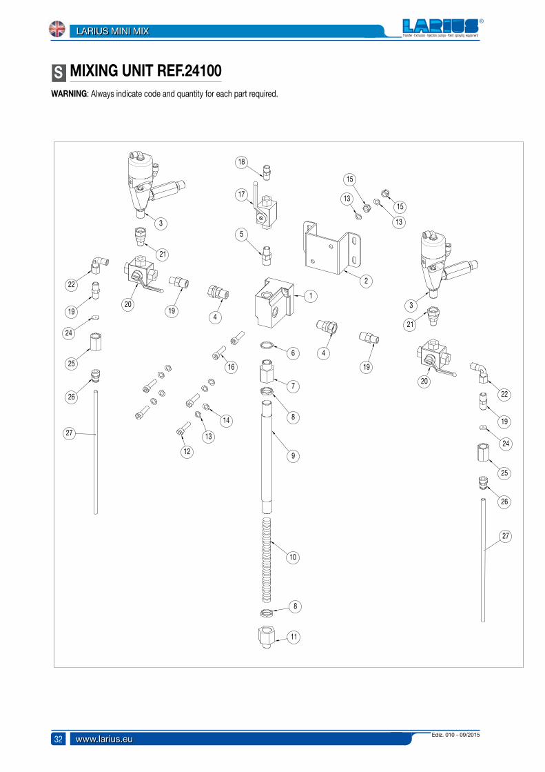
S MIXING UNIT REF.24100WARNING: Always indicate code and quantity for each part required.

Ediz. 010 - 09/2015 www.larius.eu
LARIUS MINI MIX
33
Pos.
MixerSupport plateMixer for gunsRotating connector3/8-1/4 CON-CON Adapter1/2" Gasket1/2-3/8 Adapter3/8 Locking nutMixing tubeMixing spiral3/8-1/4 AdapterScrewWasher
Code Description
1234 5,67,8910111213
Q.ty
11221112121414
Pos. Code Description Q.ty
14151617181920212224252627
NutSelf-tightening nutScrew1/4 Ball valve1/4-1/4 CON-CIL AdapterNipple 3/8-1/4Valve T 1/4 FFFJointM-F 1/4-3/8Elbow M-F 1/4Nozzle ST 15-20Sleeve FFAttachment 3/8 d8Tube Rilsan
4621142222222
233212332323340/42316123402807124102241032410424105241063940532024
410836373717798328311037107242162421898377ST 15-2024215539218153
Ediz. 010 - 09/2015www.larius.eu
LARIUS MINI MIX
34
1
8
4
3
11
5
6
7
5
2
9
10
10
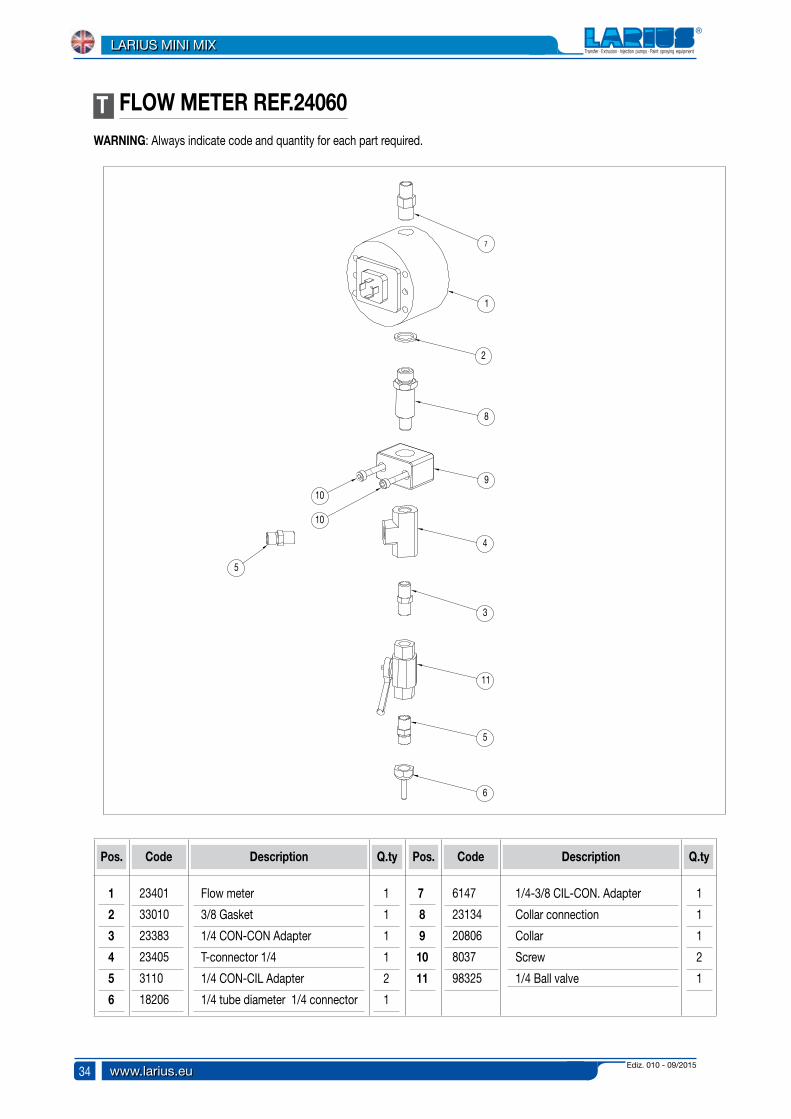
WARNING: Always indicate code and quantity for each part required.
T FLOW METER REF.24060
Pos.
Flow meter
3/8 Gasket
1/4 CON-CON Adapter
T-connector 1/4
1/4 CON-CIL Adapter
1/4 tube diameter 1/4 connector
Code Description
1
2
3
4
5,
6
Q.ty
1
1
1
1
2
1
Pos. Code Description Q.ty
7,
8
9
10
11
1/4-3/8 CIL-CON. Adapter
Collar connection
Collar
Screw
1/4 Ball valve
1
1
1
2
1
23401
33010
23383
23405
3110
18206
6147
23134
20806
8037
98325
Ediz. 010 - 09/2015 www.larius.eu
LARIUS MINI MIX
35
1
2
2
3
3
4
4
4
4
5
5
5
5
6
6
6
6
7 7
4
4
4
4
U CARRIAGE BASE REF.24040
Pos.
Carriage
Front wheels
Rear wheels
Washers
Code Description
1
2
3
4
Q.ty
1
2
2
20
Pos. Code Description Q.ty
5,
6
7,
Screw
Screw
Tap
16
4
2
24041
22087
22087/1
96753
32004
34008
95229
WARNING: Always indicate code and quantity for each part required.
Ediz. 010 - 09/2015www.larius.eu
LARIUS MINI MIX
36
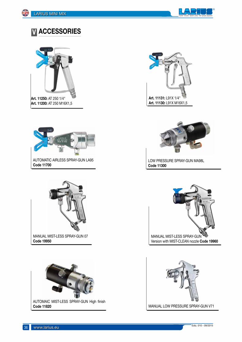
ACCESSORIESV
AUTOMATIC AIRLESS SPRAY-GUN LA95 Code 11700
LOW PRESSURE SPRAY-GUN MA98LCode 11300
MANUAL MIST-LESS SPRAY-GUN 07Code 19950
MANUAL MIST-LESS SPRAY-GUN Version with MIST-CLEAN nozzle Code 19960
AUTOMAIC MIST-LESS SPRAY-GUN High finish Code 11820 MANUAL LOW PRESSURE SPRAY-GUN V71
Art. 11250: AT 250 1/4"Art. 11200: AT 250 M16X1,5
Art. 11131: L91X 1/4"Art. 11130: L91X M16X1,5
Ediz. 010 - 09/2015 www.larius.eu
LARIUS MINI MIX
37
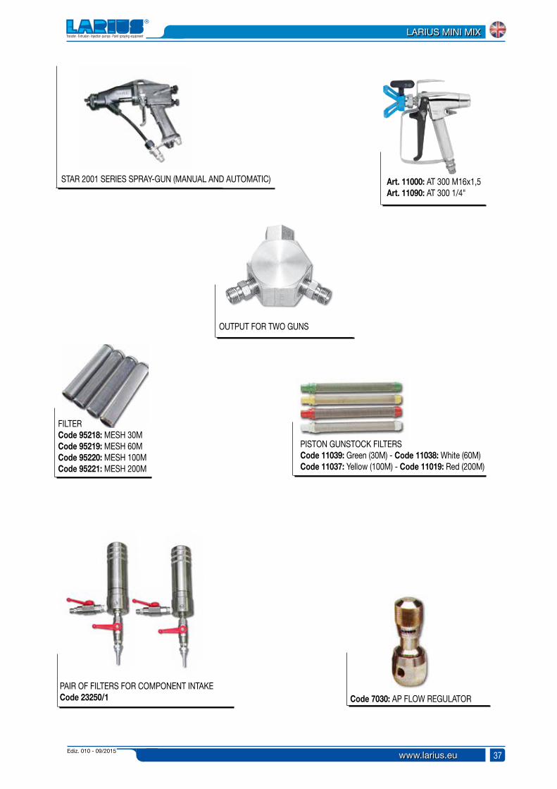
OUTPUT FOR TWO GUNS
PISTON GUNSTOCK FILTERSCode 11039: Green (30M) - Code 11038: White (60M)Code 11037: Yellow (100M) - Code 11019: Red (200M)
FILTERCode 95218: MESH 30MCode 95219: MESH 60MCode 95220: MESH 100MCode 95221: MESH 200M
Code 7030: AP FLOW REGULATOR
STAR 2001 SERIES SPRAY-GUN (MANUAL AND AUTOMATIC)
PAIR OF FILTERS FOR COMPONENT INTAKECode 23250/1
Art. 11000: AT 300 M16x1,5Art. 11090: AT 300 1/4"
Ediz. 010 - 09/2015www.larius.eu
LARIUS MINI MIX
38
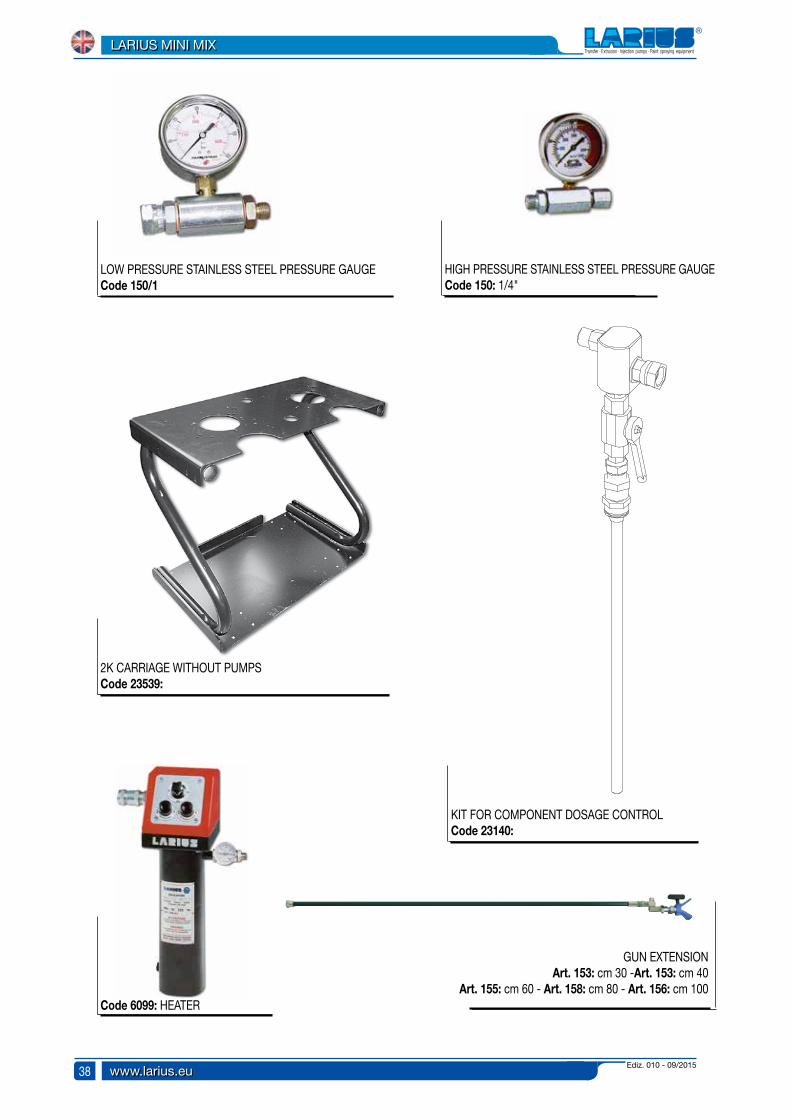
2K CARRIAGE WITHOUT PUMPSCode 23539:
KIT FOR COMPONENT DOSAGE CONTROL Code 23140:
HIGH PRESSURE STAINLESS STEEL PRESSURE GAUGECode 150: 1/4"
LOW PRESSURE STAINLESS STEEL PRESSURE GAUGECode 150/1
Code 6099: HEATER
GUN EXTENSIONArt. 153: cm 30 -Art. 153: cm 40
Art. 155: cm 60 - Art. 158: cm 80 - Art. 156: cm 100

Ediz. 010 - 09/2015 www.larius.eu
LARIUS MINI MIX
39
Art. 300: FAST-CLEAN base UE 11/16x16
FAST-CLEAN
Art. 303: GASKET
FAST-CLEAN TIP
Nozzles code
07-2007-4009-2009-4011-2011-4013-2013-4013-6015-2015-4015-6017-2017-4017-6019-2019-40
19-6021-2021-4021-6023-2023-4023-6025-2025-4025-6027-2027-4027-6027-8029-2029-4029-60
29-8031-4031-6031-8033-4033-6033-8039-4039-6039-8043-4043-6043-8051-4051-6051-80
Code 18270: SUPER FAST-CLEAN base UE 11/16x16
Art. 18280: GASKET
SUPER FAST-CLEAN TIP
SUPER FAST-CLEAN
Nozzles code
SFC07-20SFC07-40SFC09-20SFC09-40SFC11-20SFC11-40SFC13-20SFC13-40SFC13-60SFC15-20SFC15-40SFC15-60SFC17-20SFC17-40SFC17-60SFC19-20SFC19-40
SFC19-60SFC21-20SFC21-40SFC21-60SFC23-20SFC23-40SFC23-60SFC25-20SFC25-40SFC25-60SFC27-20SFC27-40SFC27-60SFC27-80SFC29-20SFC29-40SFC29-60
SFC29-80SFC31-40SFC31-60SFC31-80SFC33-40SFC33-60SFC33-80SFC39-40SFC39-60SFC39-80SFC43-40SFC43-60SFC43-80SFC51-40SFC51-60SFC51-80

Ediz. 010 - 09/2015www.larius.eu
LARIUS MINI MIX
40
1
2
2
3
3
4
4
5
5
6
3456
7 8
9
9
9
10
10
7
11
77
7
12
13
14
5
6
1516
2
ASSEMBLY DRAWING OF THE CARRIAGE FOR HIGH PRESSURE WITH MATERIAL SUCTION
Pos.
2K Carriage
Ghibli 30:1 div. stainless steel
1/2-3/8 reduction
1/4-1/4 M-F Elbow connector
3/8 ball valve
3/8 tube diameter 12 elbow attachment
3/8 tube diameter 10 air attachment
T-connector for tube diameter 10
Code Description
1
2
3
4
5,
6
7,
8
Q.ty
1
3
3
2
3
3
4
1
Pos. Code Description Q.ty
9
10
11
12
13
14
15
16
Filter with pressure gauge
Air unit
3/8-1/4 reduction
3/8 T-connector
3/8 Bayonet attachment
1/4 elbow for tube diameter 10
M-F 3/8 elbow
3/8 Adaptor
3
2
3
1
1
1
1
1
23539
96056
96261
5255
91101
91410
5390
510049
23563
91107/1
22066
3379
10103
8123
91102
91020
GHIBLI 30:1
RIF. 23540 (WITH SUCTION)
RIF. 23550 (WITH GRAVITY TANK)

Ediz. 010 - 09/2015 www.larius.eu
LARIUS MINI MIX
41
1
2
2
23
3
3
4
4
4
5
6
6
7
8
8
9
9
9
9
10
11
12
13
14
1516
12
ASSEMBLY DRAWING OF THE CARRIAGE FOR LOW PRESSURE WITH MATERIAL SUCTION
Pos.
2K CarriageLarius 2 with regulatorsFlow regulatorNutSelf-tightening nutWasherScrewAir unit3/8 tube diameter 10 air attachment
Description Q.ty
133312241224
Code Q.ty
3/8 Bayonet attachment3/8 T-connector1/4 elbow for tube diameter 10T-connector for tube diameter 8M-F 3/8 elbow3/8 CON Adaptor3/8 ball valveComplete suction tube
11211113
235398000K720181073637967533400891107/15392
1010333795100885100209110291020911018144
LARIUS 2
RIF. 23551 (WITH SUCTION)
RIF. 23541 (WITH GRAVITY TANK)

Ediz. 010 - 09/2015www.larius.eu
LARIUS MINI MIX
42
1
2
2
3
3
4
4
5
5
6
34567 8
9
9
9
10
10
7
11
77
7
12
13
14
5
6
1516
2
ASSEMBLY DRAWING OF THE CARRIAGE FOR LOW PRESSURE WITH MATERIAL SUCTION
2K CarriageVega 5:11/2-3/8 reductionElbow connector 1/4-1/4 M-F3/8 ball valve3/8 tube diameter 12 elbow attachment3/8 tube diameter 10 elbow attachmentT-connector for tube diameter 10
Code
1234 5,67,8
13323341
Pos. Code Description Q.ty
910111213141516
Filter with pressure gaugeAir unit1/4-3/8 reduction3/8 T-connector3/8 Bayonet attachment1/4 elbow for tube diameter 10M-F 3/8 elbow3/8 Adaptor
32311111
235399136396261525591101914105390510049
2356391107/12206633791010381239110291020
VEGA 5:1
RIF. 23543 (WITH SUCTION)
RIF. 2354 (WITH GRAVITY TANK)

Ediz. 010 - 09/2015 www.larius.eu
LARIUS MINI MIX
43
1
2
3
4
5
6
7
8
9
9
8
10
11
12
13
14
ASSEMBLY DRAWING OF THE FILTER FOR CARRIAGE 2K REF.23563
Pos.
Fitting wih pressure gaugeFilter tankFilter sieve springScreen filterScreen supportGasketFilter base
Code Description
1234 5,67,
Q.ty
1111111
Pos. Code Description Q.ty
891011121314
1/4-1/4 CON AdaptorBall valve1/4 AdaptorElbow connector 1/4Copper sealConnectorTap 1/4
2211111
150983849620295220962079620396206
2338398325983835255330123301598386
PAINT SPRAYING EQUIPMENT
L’innovazione.Quella vera.

PAINT SPRAYING EQUIPMENT
L’innovazione.Quella vera.
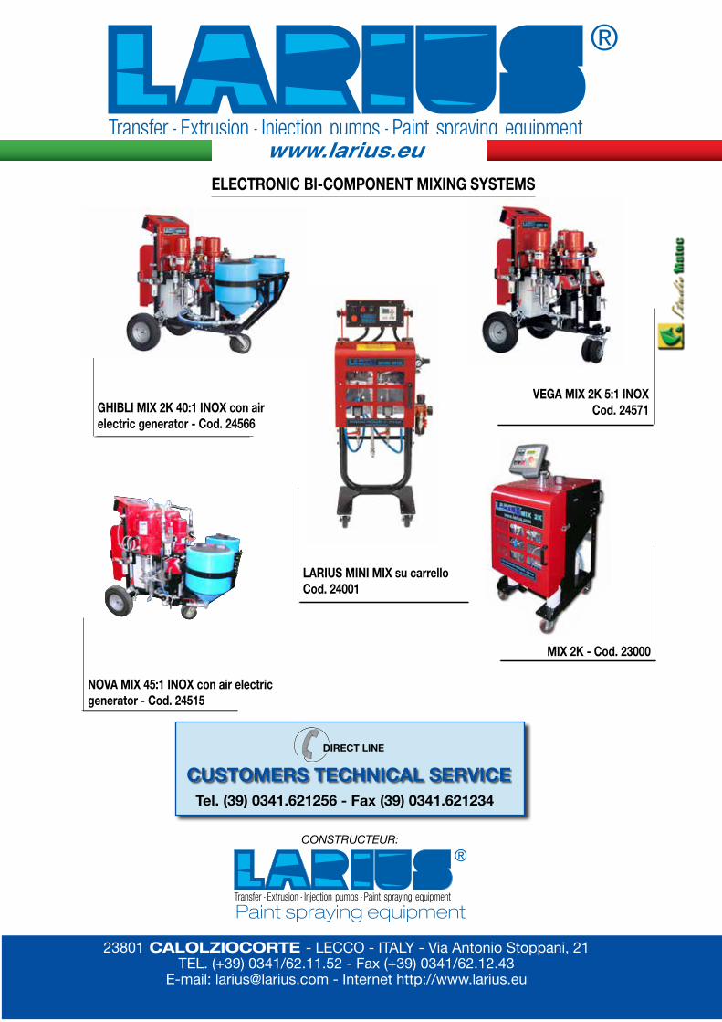
ELECTRONIC BI-COMPONENT MIXING SYSTEMS
GHIBLI MIX 2K 40:1 INOX con airelectric generator - Cod. 24566
VEGA MIX 2K 5:1 INOX Cod. 24571
LARIUS MINI MIX su carrello Cod. 24001
NOVA MIX 45:1 INOX con air electric generator - Cod. 24515
MIX 2K - Cod. 23000
DIRECT LINE
CUSTOMERS TECHNICAL SERVICETel. (39) 0341.621256 - Fax (39) 0341.621234
www.larius.eu
23801 CALOLZIOCORTE - LECCO - ITALY - Via Antonio Stoppani, 21TEL. (+39) 0341/62.11.52 - Fax (+39) 0341/62.12.43
E-mail: [email protected] - Internet http://www.larius.eu
CONSTRUCTEUR:
Paint spraying equipment


![Fumes Et Al. 2014 [Deciduous Teeth]](https://static.fdocuments.net/doc/165x107/577c83a81a28abe054b5b1d5/fumes-et-al-2014-deciduous-teeth.jpg)