
Laboratory Testing Methods of Cavitation Erosion
16
Chapter 2 Laboratory Testing Methods of Cavitation Erosion Georges L. Chahine, Jean-Pierre Franc and Ayat Karimi Abstract This chapter presents in detail several cavitation erosion testing meth- ods commonly used in the laboratory. The vibratory cavitation apparatus (G32) is described with its two variants, the direct method using a specimen attached to the vibrating tip of the ultrasonic horn and the alternative method using a fixed specimen facing the horn tip. In the cavitating jet apparatus (G134 and its vari- ants), a jet is discharged at high pressure and velocity in a cell whose pressure may be controlled to adjust the cavitation number. This results in a shear type cavitation whose aggressiveness may be enhanced by a proper design of the nozzle shape and piping assembly. A high-speed cavitation tunnel equipped with a radial divergent test section is also presented. This particular test section generates an unsteady cavity attached to the nozzle exit with cavitation erosion damage concentrated in the cavity closure region. Usual testing procedures together with typical erosion patterns and mass loss results obtained in such facilities are also presented. 2.1 Introduction Proper evaluation of new materials for their resistance to cavitation erosion requires a comprehensive effort addressing both the intensity of the cavitation field and the resistance of the material. In the absence of historical data on the G. L. Chahine (&) DYNAFLOW, INC., 10621-J Iron Bridge Road, Jessup, MD, USA e-mail: glchahine@dynaflow-inc.com J.-P. Franc (&) LEGI, Grenoble, France e-mail: [email protected] A. Karimi (&) EPFL, Lausanne, Switzerland e-mail: ayat.karimi@epfl.ch K.-H. Kim et al. (eds.), Advanced Experimental and Numerical Techniques for Cavitation Erosion Prediction, Fluid Mechanics and Its Applications 106, DOI: 10.1007/978-94-017-8539-6_2, ȑ Springer Science+Business Media Dordrecht 2014 21
Transcript of Laboratory Testing Methods of Cavitation Erosion
Chapter 2Laboratory Testing Methods of CavitationErosion
Georges L. Chahine, Jean-Pierre Franc and Ayat Karimi
Abstract This chapter presents in detail several cavitation erosion testing meth-ods commonly used in the laboratory. The vibratory cavitation apparatus (G32) isdescribed with its two variants, the direct method using a specimen attached to thevibrating tip of the ultrasonic horn and the alternative method using a fixedspecimen facing the horn tip. In the cavitating jet apparatus (G134 and its vari-ants), a jet is discharged at high pressure and velocity in a cell whose pressure maybe controlled to adjust the cavitation number. This results in a shear type cavitationwhose aggressiveness may be enhanced by a proper design of the nozzle shape andpiping assembly. A high-speed cavitation tunnel equipped with a radial divergenttest section is also presented. This particular test section generates an unsteadycavity attached to the nozzle exit with cavitation erosion damage concentrated inthe cavity closure region. Usual testing procedures together with typical erosionpatterns and mass loss results obtained in such facilities are also presented.
2.1 Introduction
Proper evaluation of new materials for their resistance to cavitation erosionrequires a comprehensive effort addressing both the intensity of the cavitation fieldand the resistance of the material. In the absence of historical data on the
G. L. Chahine (&)DYNAFLOW, INC., 10621-J Iron Bridge Road, Jessup, MD, USAe-mail: [email protected]
J.-P. Franc (&)LEGI, Grenoble, Francee-mail: [email protected]
A. Karimi (&)EPFL, Lausanne, Switzerlande-mail: [email protected]
K.-H. Kim et al. (eds.), Advanced Experimental and Numerical Techniquesfor Cavitation Erosion Prediction, Fluid Mechanics and Its Applications 106,DOI: 10.1007/978-94-017-8539-6_2, � Springer Science+Business Media Dordrecht 2014
21
performance of a new material in the target cavitating flow fields, experimentalstudies in the laboratory offer a convenient means of assessing the cavitationerosion performance.
Field erosion studies have been conducted for hydraulic turbines and pumps(e.g. [1–5]), but for marine applications, small scale laboratory tests are morecommon. These laboratory experimental studies aim at obtaining within therequired short time periods an evaluation of the cavitation resistance of the newmaterial, whereas in the real field cavitation erosion may occur after a longduration of exposure.
Such accelerated erosion test techniques include the utilization of ultrasonicvibration devices to generate the cavitation [6–8], cavitation flow loops with strongflow separation, vortex or venturi effects [9–11], rotating discs and submergedcavitating jets [12–15], and other methods. There are also attempts to test modelpropellers in water tunnels [16].
Some of these techniques are standardized and follow the American Society forTesting and Materials (ASTM) Standards [17]. The ultrasonic technique and theliquid jet technique are the two most popular laboratory techniques for testingcavitation erosion characteristics of materials.
In this chapter, three different laboratory testing methods and equipments arepresented in detail, and are used to generate the erosion data presented in Part 1 ofthis book. They are vibratory devices (ASTM G32), cavitating liquid jets (ASTMG134), and a high-speed cavitation tunnel.
2.2 Vibratory Cavitation Apparatus (ASTM G32)
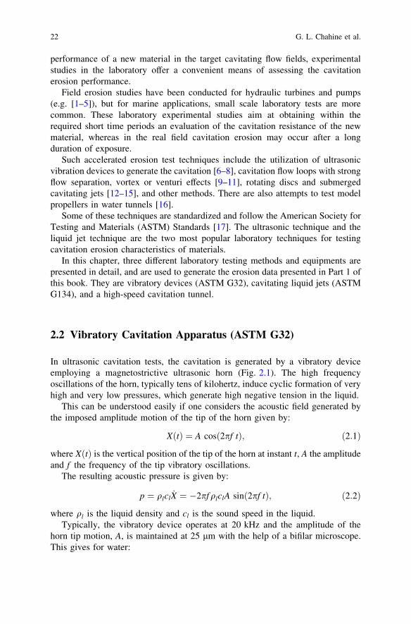
In ultrasonic cavitation tests, the cavitation is generated by a vibratory deviceemploying a magnetostrictive ultrasonic horn (Fig. 2.1). The high frequencyoscillations of the horn, typically tens of kilohertz, induce cyclic formation of veryhigh and very low pressures, which generate high negative tension in the liquid.
This can be understood easily if one considers the acoustic field generated bythe imposed amplitude motion of the tip of the horn given by:
XðtÞ ¼ A cosð2pf tÞ; ð2:1Þ
where XðtÞ is the vertical position of the tip of the horn at instant t, A the amplitudeand f the frequency of the tip vibratory oscillations.
The resulting acoustic pressure is given by:
p ¼ qlcl _X ¼ �2pf qlclA sinð2pf tÞ; ð2:2Þ
where ql is the liquid density and cl is the sound speed in the liquid.Typically, the vibratory device operates at 20 kHz and the amplitude of the
horn tip motion, A, is maintained at 25 lm with the help of a bifilar microscope.This gives for water:
22 G. L. Chahine et al.
p ¼ �4:7� 106 sinð2pf tÞ Pascals: ð2:3Þ
Since the amplitude of the pressure oscillations is much larger than the ambientpressure (actually 47 atmospheres), this results in pressure drops during the neg-ative pulse cycle much below the critical pressure of most liquids (see Sect. 1.1.3).
A sample ‘‘button’’ of the material being tested is affixed to the end of the hornand is subjected to the cavitation resulting from the vibration of the horn. Ahemispherical cavitation cloud forms at the exposed face of the sample and exe-cutes severe dynamics resulting in bubble cloud growth and collapse. The ASTMG32-09 [17, 18] specifies the sample diameter, 16 mm, the vibration frequency,20 kHz, and amplitude, 50 lm peak-to-peak, and the shape and size of the con-tainer in order to minimize variations among different tests and laboratories due toacoustic interaction between transducer and container. A 2,000 ml beaker filledwith distilled water and with the tip of the horn submerged 8 mm beneath the freesurface is required. In addition, the temperature is controlled by immersing thebeaker in a water bath maintained at 25 ± 2 �C.
In an ‘‘alternative’’ G32 test configuration [12, 19] (also known as the stationaryspecimen method), a stationary material sample is placed at a small distance,typically 0.5 mm, below the vibrating horn tip made of a cavitation resistantbutton (e.g. Titanium). Deviations from the ASTM G32 method have to be doc-umented. The cavitation erosion tests presented in Chap. 5 used a sample diameterof 12.7 mm instead of 16 mm recommended by the ASTM for both the direct andalternative methods. The alternative G32 method is especially useful for testing
Fig. 2.1 Ultrasonic cavitation erosion test setup at DYNAFLOW. The ultrasonic horn tip vibrates at20 kHz and generates cavitation bubbles around the tip. The right picture shows the alternativeG32 configuration. The sample is placed in the square support plate below the cylindrical horn.The reddish tip is the Titanium ‘‘button’’. Cavitation under the horn is difficult to see as it is limitedto the gap between the ‘‘button’’ and the sample. The white spots are bubbles generated by thevibrations at the free surface of the container and at the periphery of the sample holder
2 Laboratory Testing Methods of Cavitation Erosion 23
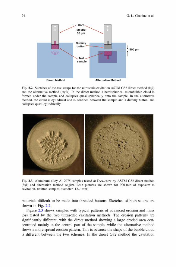
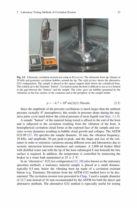
materials difficult to be made into threaded buttons. Sketches of both setups areshown in Fig. 2.2.
Figure 2.3 shows samples with typical patterns of advanced erosion and massloss tested by the two ultrasonic cavitation methods. The erosion patterns aresignificantly different, with the direct method showing a large eroded area con-centrated mainly in the central part of the sample, while the alternative methodshows a more spread erosion pattern. This is because the shape of the bubble cloudis different between the two schemes. In the direct G32 method the cavitation
Horn
20 kHz 50 µm
Direct Method
Test sample
Dummy button
Alternative Method
500 µm
Fig. 2.2 Sketches of the test setups for the ultrasonic cavitation ASTM G32 direct method (left)and the alternative method (right). In the direct method a hemispherical microbubble cloud isformed under the sample and collapses quasi spherically onto the sample. In the alternativemethod, the cloud is cylindrical and is confined between the sample and a dummy button, andcollapses quasi-cylindrically
Fig. 2.3 Aluminum alloy Al 7075 samples tested at DYNAFLOW by ASTM G32 direct method(left) and alternative method (right). Both pictures are shown for 900 min of exposure tocavitation. (Button samples diameter: 12.7 mm)
24 G. L. Chahine et al.
cloud collapses in a hemispherical way towards the tested sample (see Fig. 2.2left), while in the alternative method, the cavitation bubble cloud collapses in acylindrical way (see Fig. 2.2 right). Cavitation clouds collapsing cylindricallywere found to be much less erosive than the hemi-spherically collapsing cavitationclouds [12, 19].
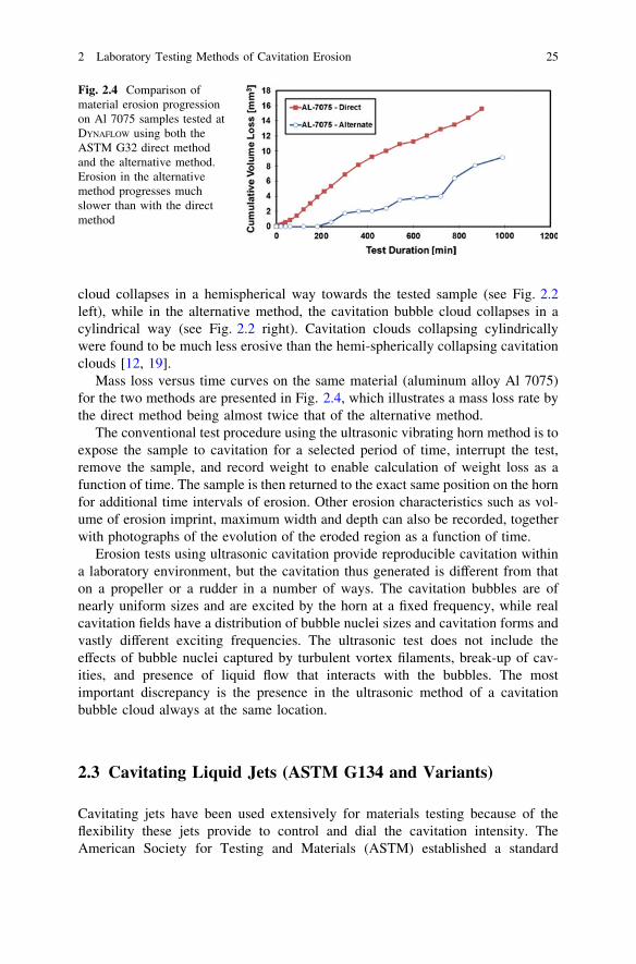
Mass loss versus time curves on the same material (aluminum alloy Al 7075)for the two methods are presented in Fig. 2.4, which illustrates a mass loss rate bythe direct method being almost twice that of the alternative method.
The conventional test procedure using the ultrasonic vibrating horn method is toexpose the sample to cavitation for a selected period of time, interrupt the test,remove the sample, and record weight to enable calculation of weight loss as afunction of time. The sample is then returned to the exact same position on the hornfor additional time intervals of erosion. Other erosion characteristics such as vol-ume of erosion imprint, maximum width and depth can also be recorded, togetherwith photographs of the evolution of the eroded region as a function of time.
Erosion tests using ultrasonic cavitation provide reproducible cavitation withina laboratory environment, but the cavitation thus generated is different from thaton a propeller or a rudder in a number of ways. The cavitation bubbles are ofnearly uniform sizes and are excited by the horn at a fixed frequency, while realcavitation fields have a distribution of bubble nuclei sizes and cavitation forms andvastly different exciting frequencies. The ultrasonic test does not include theeffects of bubble nuclei captured by turbulent vortex filaments, break-up of cav-ities, and presence of liquid flow that interacts with the bubbles. The mostimportant discrepancy is the presence in the ultrasonic method of a cavitationbubble cloud always at the same location.
2.3 Cavitating Liquid Jets (ASTM G134 and Variants)
Cavitating jets have been used extensively for materials testing because of theflexibility these jets provide to control and dial the cavitation intensity. TheAmerican Society for Testing and Materials (ASTM) established a standard
Fig. 2.4 Comparison ofmaterial erosion progressionon Al 7075 samples tested atDYNAFLOW using both theASTM G32 direct methodand the alternative method.Erosion in the alternativemethod progresses muchslower than with the directmethod
2 Laboratory Testing Methods of Cavitation Erosion 25
method using specific conditions and orifice type under the G134 in 1995 [20].Cavitation intensity produced by cavitating jets can be varied in a wide rangethrough adjustment of the type of the jet, the jet velocity, the jet diameter, the jetangle, the standoff distance, and the ambient pressure in which they are discharged[14]. The jet pressure can be as high as 300 MPa for some applications. Thisflexibility makes a cavitating jet a useful research and testing tool to study para-metrically the effect of cavitation intensity on material behavior.
Compared to the ultrasonic horn testing (G32), the cavitation generated by acavitating jet provides more realistic cavitation bubble clouds than that by ultra-sonic horn, with distribution of various size micro bubbles, shear flows withvortices, and dense bubble clouds, which collapse on the sample. With the controlof the operating pressure, the jet angle, and the standoff, the testing time can becontrolled to provide either quick erosion for an initial screening or acceleratederosion more relevant to the real flows.
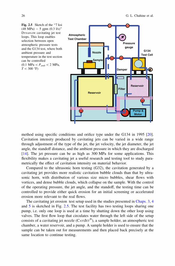
The cavitating jet erosion test setup used in the studies presented in Chaps. 3, 4and 5 is sketched in Fig. 2.5. The test facility has two testing loops sharing onepump, i.e. only one loop is used at a time by shutting down the other loop usingvalves. The first flow loop that circulates water through the left side of the setupconsists of a cavitating jet nozzle (CAVIJET
�), a sample holder, an atmospheric testchamber, a water reservoir, and a pump. A sample holder is used to ensure that thesample can be taken out for measurements and then placed back precisely at thesame location to continue testing.
Reservoir
Reservoir
Damper
Filter
Pump & Motor
Pressure gauge
Nozzle
Sample
G134Test Cell
Atmospheric Test Chamber
Fig. 2.5 Sketch of the ‘‘7 ksi(48 MPa) - 5 gpm (0.3 l/s)’’DYNAFLOW cavitating jet testloops. This loop enablesselection between openatmospheric pressure testsand the G134 test, where bothambient pressure andtemperature in the test sectioncan be controlled(0.1 MPa \ Pamb \ 2 MPa,T \ 300 �F)
26 G. L. Chahine et al.
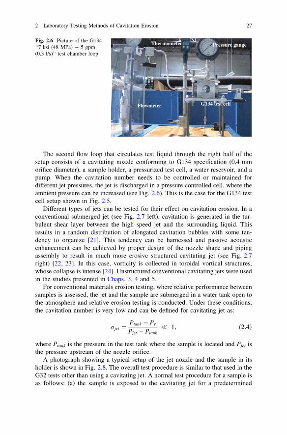
The second flow loop that circulates test liquid through the right half of thesetup consists of a cavitating nozzle conforming to G134 specification (0.4 mmorifice diameter), a sample holder, a pressurized test cell, a water reservoir, and apump. When the cavitation number needs to be controlled or maintained fordifferent jet pressures, the jet is discharged in a pressure controlled cell, where theambient pressure can be increased (see Fig. 2.6). This is the case for the G134 testcell setup shown in Fig. 2.5.
Different types of jets can be tested for their effect on cavitation erosion. In aconventional submerged jet (see Fig. 2.7 left), cavitation is generated in the tur-bulent shear layer between the high speed jet and the surrounding liquid. Thisresults in a random distribution of elongated cavitation bubbles with some ten-dency to organize [21]. This tendency can be harnessed and passive acousticenhancement can be achieved by proper design of the nozzle shape and pipingassembly to result in much more erosive structured cavitating jet (see Fig. 2.7right) [22, 23]. In this case, vorticity is collected in toroidal vortical structures,whose collapse is intense [24]. Unstructured conventional cavitating jets were usedin the studies presented in Chaps. 3, 4 and 5.
For conventional materials erosion testing, where relative performance betweensamples is assessed, the jet and the sample are submerged in a water tank open tothe atmosphere and relative erosion testing is conducted. Under these conditions,the cavitation number is very low and can be defined for cavitating jet as:
rjet ¼Ptank � Pv
Pjet � Ptank� 1; ð2:4Þ
where Ptank is the pressure in the test tank where the sample is located and Pjet isthe pressure upstream of the nozzle orifice.
A photograph showing a typical setup of the jet nozzle and the sample in itsholder is shown in Fig. 2.8. The overall test procedure is similar to that used in theG32 tests other than using a cavitating jet. A normal test procedure for a sample isas follows: (a) the sample is exposed to the cavitating jet for a predetermined
Flowmeter G134 test cell
Thermometer Pressure gaugeFig. 2.6 Picture of the G134‘‘7 ksi (48 MPa) - 5 gpm(0.3 l/s)’’ test chamber loop
2 Laboratory Testing Methods of Cavitation Erosion 27

Fig. 2.7 Conventional CAVIJET� cavitating jet (left) and structured cavitating jet generated by a
STRATOJET� (right). Both pictures were taken using large scale nozzles geometrically scaled up
while conserving cavitation number and Strouhal number. The left CAVIJET� nozzle had an orifice
diameter of 2.5 cm, while the right STRATOJET� orifice had a diameter of 1 cm. The cavitating
vortex rings in the STRATOJET� were emitted with a frequency corresponding to a Strouhal
number of 0.3 at the cavitation number of 0.5
Sample holder
Nozzle
Sample
Erosion pattern
Sample holder
Nozzle
Sample
Fig. 2.8 A typical cavitating jet erosion test setup at DYNAFLOW (left): the sample is 2.5cm 9 2.0 cm 9 2.5 cm. The nozzle diameter is about 2 mm and the standoff distance is about2.5 cm. The right picture shows more specialized testing; here a cylindrically shaped sample isplaced under the nozzle. The whole rod piece can be held in place under the jet. The jet and thesamples shown in the pictures are submerged in water during the test
28 G. L. Chahine et al.

period of time, (b) the test is interrupted, (c) the sample is taken out from its holderfor examination, and (d) the erosion is characterized by weight and depth mea-surement. Photographs of the progression of the erosion patterns such as shown inFig. 2.9 are taken at selected times. The sample is then returned for additionaltesting, and the process is repeated. The time intervals are appropriately selected tocapture a cumulative weight loss curve displaying as much as possible the char-acteristic S-curve (see Chap. 5).
2.4 High-speed Cavitation Tunnels
Cavitation erosion tests can also be conducted in high-speed cavitation tunnels. Inorder to be able to characterize the resistance to cavitation erosion of hardmaterials within reasonable exposure times, cavitating flows of sufficiently highaggressiveness are required. As aggressiveness increases with flow velocity,cavitation erosion tunnels are often designed for high velocities and consequentlyhigh pressures.
Figure 2.10 presents a typical example of such a facility. The whole facility isdesigned for a maximum pressure of 4 MPa (40 bar) corresponding to a maximumvelocity of about 90 m/s. The facility is equipped with a 80 kW centrifugal pump,which can provide a flow rate of up to 11 l/s. A heat exchanger of 80 kW limits theincrease in temperature during long duration tests.
The facility comprises a downstream tank of 1 m3 pressurized with nitrogen bymeans of a pressurization vessel. The small section of the pressurization vessellimits the dissolution of nitrogen into water so that the dissolved gas content isexpected to be almost independent of the pressurization level. Pressurization isrequired to control the cavitation number which, in turn, controls the extent of
Fig. 2.9 Cavitation erosion pattern on metals created by a CAVIJET� cavitating jet. The left figure
shows the erosion pattern on the rod sample shown in Fig. 2.8 (right), which explains theelliptical shape of the eroded area. The right picture shows a more typical erosion pattern on a flatsample. In both pictures the erosion areas had typical size of the order of a centimeter, thesamples were surface treated proprietary stainless steels and the jet pressure was about 40 MPa
2 Laboratory Testing Methods of Cavitation Erosion 29
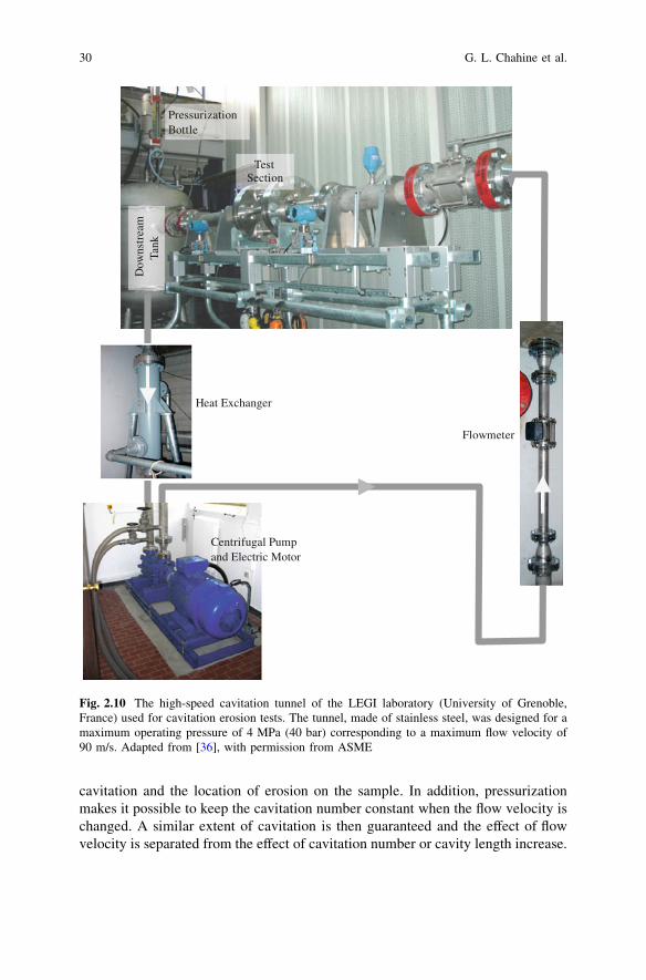
cavitation and the location of erosion on the sample. In addition, pressurizationmakes it possible to keep the cavitation number constant when the flow velocity ischanged. A similar extent of cavitation is then guaranteed and the effect of flowvelocity is separated from the effect of cavitation number or cavity length increase.
Dow
nstr
eam
Tank
Heat Exchanger
Flowmeter
Test Section
PressurizationBottle
Centrifugal Pumpand Electric Motor
Fig. 2.10 The high-speed cavitation tunnel of the LEGI laboratory (University of Grenoble,France) used for cavitation erosion tests. The tunnel, made of stainless steel, was designed for amaximum operating pressure of 4 MPa (40 bar) corresponding to a maximum flow velocity of90 m/s. Adapted from [36], with permission from ASME
30 G. L. Chahine et al.
Several pressure sensors are used to control the operating point. A flow metermeasures the flow rate Q in the test section and two pressure sensors give theupstream and downstream pressures Pu and Pd respectively. They are located farupstream and downstream of the test section in the inlet and outlet ducts of largediameter (90 mm) with respect to that of the nozzle (16 mm).
The cavitation number is defined by:
r ¼ Pd � Pv
Pu � Pd; ð2:5Þ
where Pv is the liquid vapor pressure. A temperature sensor is also used to checkthat the temperature rise during long erosion tests remains limited to typically afew degrees Celsius.
Different types of test sections have been used to investigate cavitation erosionin high-speed tunnels such as a Venturi with or without a central body [25–27],slot cavitator [28–34], cylindrical specimen spanning the tunnel [35] or radialdivergent [36].
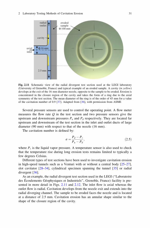
As an example, the radial divergent test section used in the LEGI (‘‘Laboratoiredes Écoulements Géophysiques et Industriels’’, Grenoble, France) facility is pre-sented in more detail in Figs. 2.11 and 2.12. The inlet flow is axial whereas theoutlet flow is radial. Cavitation develops from the nozzle exit and extends into theradial diverging channel. The sample to be eroded faces the nozzle and is locatedat a distance of 2.5 mm. Cavitation erosion has an annular shape similar to theshape of the closure region of the cavity.
16 mm
2.5 mm
radial outlet
eroded sample100 mm
axial inlet
cavity
Fig. 2.11 Schematic view of the radial divergent test section used at the LEGI laboratory(University of Grenoble, France) and typical example of an eroded sample. A cavity (in yellow)develops at the exit of the 16 mm diameter nozzle, opposite to the sample to be eroded. Erosion isconcentrated in the closure region of the cavity and takes the form of a ring due to the axialsymmetry of the test section. The mean diameter of the ring is of the order of 45 mm for a valueof the cavitation number of 0.9 [37]. Adapted from [36], with permission from ASME
2 Laboratory Testing Methods of Cavitation Erosion 31
For the erosion tests conducted at LEGI, the tunnel is usually operated at acavitation number around 0.9. With this value of r, the cavity closure point islocated at a radial distance of the order of 22.5 mm from the axis (see Fig. 2.13).Using the definition (2.5) of the cavitation number, the pressure drop through thetest section is:
Pu � Pd ¼Pu � Pv
1þ r: ð2:6Þ
In this equation, the vapor pressure Pv is generally negligible with respect to theupstream pressure. Since the cavitation number is around 1, Eq. (2.6) shows thatthe downstream pressure, Pd, in the cavitating test section, and the pressure dropacross the nozzle, Pu � Pd, are each about half the upstream pressure.
Using Bernoulli equation, a typical velocity on the cavity can be derived:
Vc ffiffiffiffiffiffiffiffiffi
2Pu
q
s
; ð2:7Þ
where q is the liquid density. Equation (2.7) assumes that the pressure on thecavity surface (which is expected to be close to the vapor pressure) is negligiblewith respect to the upstream pressure and that the velocity in the inlet duct of largediameter (90 mm) is negligible with respect to the velocity in the test section. Asan example, for an upstream pressure of 4 MPa, the velocity on the cavity isVc ffi 90 m=s. For this typical operating point, the measured flowrate is 8.2 l/s. Theequivalent flow velocity in the minimum section area corresponding to thecylindrical section of diameter 16 mm and thickness 2.5 mm at the exit of the
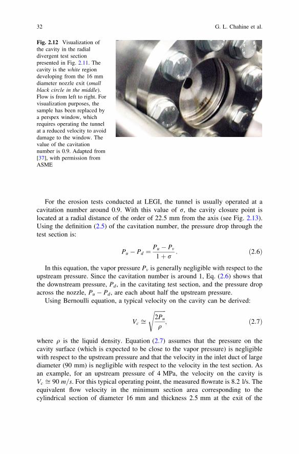
Fig. 2.12 Visualization ofthe cavity in the radialdivergent test sectionpresented in Fig. 2.11. Thecavity is the white regiondeveloping from the 16 mmdiameter nozzle exit (smallblack circle in the middle).Flow is from left to right. Forvisualization purposes, thesample has been replaced bya perspex window, whichrequires operating the tunnelat a reduced velocity to avoiddamage to the window. Thevalue of the cavitationnumber is 0.9. Adapted from[37], with permission fromASME
32 G. L. Chahine et al.
nozzle (see Fig. 2.11) is 65 m/s. This estimate assumes that the flow in this sectionis purely liquid.
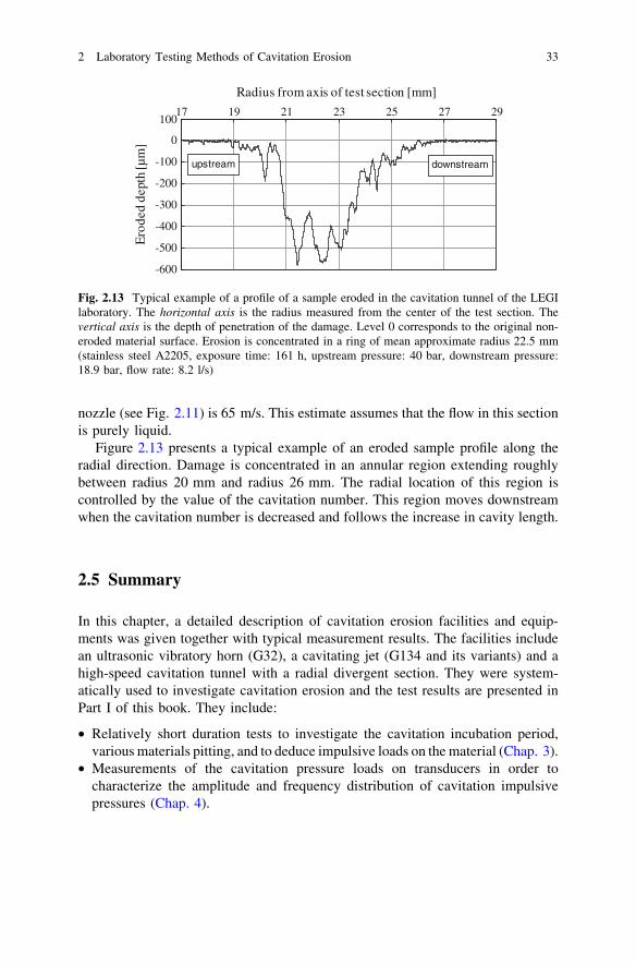
Figure 2.13 presents a typical example of an eroded sample profile along theradial direction. Damage is concentrated in an annular region extending roughlybetween radius 20 mm and radius 26 mm. The radial location of this region iscontrolled by the value of the cavitation number. This region moves downstreamwhen the cavitation number is decreased and follows the increase in cavity length.
2.5 Summary
In this chapter, a detailed description of cavitation erosion facilities and equip-ments was given together with typical measurement results. The facilities includean ultrasonic vibratory horn (G32), a cavitating jet (G134 and its variants) and ahigh-speed cavitation tunnel with a radial divergent section. They were system-atically used to investigate cavitation erosion and the test results are presented inPart I of this book. They include:
• Relatively short duration tests to investigate the cavitation incubation period,various materials pitting, and to deduce impulsive loads on the material (Chap. 3).
• Measurements of the cavitation pressure loads on transducers in order tocharacterize the amplitude and frequency distribution of cavitation impulsivepressures (Chap. 4).
-600
-500
-400
-300
-200
-100
0
10017 19 21 23 25 27 29
Ero
ded
dept
h [µ
m]
Radius from axis of test section [mm]
upstream downstream
Fig. 2.13 Typical example of a profile of a sample eroded in the cavitation tunnel of the LEGIlaboratory. The horizontal axis is the radius measured from the center of the test section. Thevertical axis is the depth of penetration of the damage. Level 0 corresponds to the original non-eroded material surface. Erosion is concentrated in a ring of mean approximate radius 22.5 mm(stainless steel A2205, exposure time: 161 h, upstream pressure: 40 bar, downstream pressure:18.9 bar, flow rate: 8.2 l/s)
2 Laboratory Testing Methods of Cavitation Erosion 33
• Long duration tests to characterize mass loss evolution with time due to cavi-tation erosion on various materials for different cavitation aggressiveness levels(Chap. 5).
References
1. Billet M (2005) The special committee on cavitation erosion on propellers and appendages onhigh powered/high speed ships. Paper presented at the 24th International Towing TankConference (ITTC), Edinburgh, UK, 4–10 Sept 2005
2. Grekula M, Bark G (2001) Experimental study of cavitation in a kaplan model turbine. Paperpresented at the 4th International Symposium on Cavitation (CAV2001), Pasadena, CA,20–23 Jun 2001
3. Farhat M, Bourdon P (1998) Extending repair intervals of hydro turbines by mitigatingcavitation erosion. Paper presented at the CEA Electricity’98 Conference and Exposition,Toronto, 26–29 Apr 1998
4. Farhat M, Bourdon P, Lavigne P, Simoneau R (1997) The hydrodynamic aggressiveness ofcavitating flows in hydro turbines. Paper presented at the ASME Fluids Engineering DivisionSummer Meeting, Vancouver, BC, 22–26 Jun 1997
5. Turbomachinery Society of Japan (2010) Guideline for prediction and evaluation ofcavitation erosion in pumps. Tokyo
6. Hammitt FG, Chao C, Kling CL, Mitchell TM, Rogers DO (1970) Round-Robin test withvibratory cavitation and liquid impact facilities of 6061–T 6511 aluminum alloy, 316stainless steel and commercially pure nickel. Mater Res Stand 10:16–36
7. Chao C, Hammitt FG, Kling CL (1968) ASTM round-robin test with vibratory cavitation andliquid impact facilities of 6061–T6 aluminum alloy, 316 stainless steel, commercially purenickel, vol 84. The University of Michigan Report MMPP-344-3-T/01357-4-T, Ann Arbor
8. Light KH (2005) Development of a cavitation erosion resistant advanced material system.Master of science thesis, The University of Maine, Orono, ME
9. Dominguez-Cortazar MA, Franc J-P, Michel J-M (1997) The erosive axial collapse of acavitating vortex: an experimental study. J Fluids Eng 119(3):686–691
10. Hammitt FG (1966) Damage to solids caused by cavitation. Philos Trans R Soc of Lond SerA Math Phys Sci 260(1110):245–255
11. Escaler X, Avellan F, Egusquiza E (2001) Cavitation erosion prediction from inferred forcesusing material resistance data. Paper presented at the 4th international symposium oncavitation, Pasadena, California, 20–23 Jun 2001
12. March PA (1987) Evaluating the relative resistance of materials to cavitation erosion: acomparison of cavitating jet results and vibratory results. Paper presented at the ASMEcavitation and multiphase flow forum, Cincinnati, 14–17 Jun 1987
13. Momma T, Lichtarowicz A (1995) A study of pressures and erosion produced by collapsingcavitation. Wear 186–187(Part 2):425–436. doi:10.1016/0043-1648(95)07144-x
14. Chahine GL, Courbière P (1987) Noise and erosion of self-resonating cavitating jets. J FluidsEng 109(4):429–435
15. Lee MK, Kim WW, Rhee CK, Lee WJ (1999) Liquid impact erosion mechanism andtheoretical impact stress analysis in tin-coated stream turbine blade materials. Metall MaterTrans A 30A:961–968
16. Pfitsch W, Gowing S, Fry D, Donnelly M, Jessup S (2009) Development of measurementtechniques for studying propeller erosion damage in severe wake fields. Paper presented atthe 7th international symposium on cavitation (CAV2009), Ann Arbor, Michigan, 17–22 Aug2009
34 G. L. Chahine et al.
17. Annual Book of ASTM Standards (2010) Section 3: metals test methods and analyticalprocedures, vol 03.02. Annual Book of ASTM Standards, West Conshohocken
18. Designation: G 32-09: Standard Test Method for Cavitation Erosion Using VibratoryApparatus. Annual Book of ASTM Standards (2010) Section 3: Metals test methods andanalytical procedures, vol 03.02. West Conshohocken, pp 94–109
19. Hansson I, Mørch KA (1980) The dynamics of cavity clusters in ultrasonic (vibratory)cavitation erosion. J Appl Phys 51(9):4651–4658
20. Designation: G134-95: standard test method for erosion of solid materials by a cavitatingliquid Jet. Annual Book of ASTM Standards (2010) Section 3: metals test methods andanalytical procedures, vol 03.02, West Conshohocken, pp 558–571
21. Crow SC, Champagne FH (1971) Orderly structure in jet turbulence. J Fluid Mech48(03):547–591. doi:10.1017/S0022112071001745
22. Johnson VE, Chahine GL, Lindenmuth WT, Conn AF, Frederick GS, Giacchino GJ (1984)Cavitating and structured jets for mechanical bits to increase drilling rate. Part I: theory andconcepts. J Energy Res Technol 106(2):282–288
23. Johnson VE, Chahine GL, Lindenmuth WT, Conn AF, Frederick GS, Giacchino GJ (1984)Cavitating and structured jets for mechanical bits to increase drilling rate. Part II:experimental results. J Energy Res Technol 106(2):289–294
24. Chahine GL, Genoux PF (1983) Collapse of a cavitating vortex ring. J Fluids Eng105(4):400–405
25. Hattori S, Sun B-H, Hammitt FG, Okada T (1985) An application of bubble collapse pulseheight spectra to venturi cavitation erosion of 1100-0 aluminum. Wear 103(2):119–131.doi:10.1016/0043-1648(85)90128-0
26. Franc J-P, Michel J-M (1997) Cavitation erosion research in France: the state of the art. J MarSci Technol 2:233–244
27. Okada T, Hammitt FG (1981) Cavitation erosion in vibratory and venturi facilities. Wear69(1):55–69
28. Steller J, Krella A, Koronowicz J, Janicki W (2005) Towards quantitative assessment ofmaterial resistance to cavitation erosion. Wear 258(1–4):604–613. doi:10.1016/j.wear.2004.02.015
29. Krella A (2011) An experimental parameter of cavitation erosion resistance for tin coatings.Wear 270(3–4):252–257. doi:10.1016/j.wear.2010.10.065
30. Krella A (2005) Influence of cavitation intensity on X6CrNiTi18-10 stainless steelperformance in the incubation period. Wear 258(11–12):1723–1731. doi:10.1016/j.wear.2004.11.025
31. Krella A, Czyzniewski A (2006) Cavitation erosion resistance of Cr–N coating deposited onstainless steel. Wear 260(11–12):1324–1332. doi:10.1016/j.wear.2005.09.018
32. Krella A, Czyzniewski A (2008) Cavitation erosion resistance of nanocrystalline tin coatingdeposited on stainless steel. Wear 265(7–8):963–970. doi:10.1016/j.wear.2008.02.004
33. Krella A, Czyzniewski A (2009) Cavitation resistance of Cr–N coatings deposited onaustenitic stainless steel at various temperatures. Wear 266(7–8):800–809. doi:10.1016/j.wear.2008.11.002
34. Krella A, Czyzniewski A (2007) Influence of the substrate hardness on the cavitation erosionresistance of tin coating. Wear 263(1–6):395–401. doi:10.1016/j.wear.2007.02.003
35. Coleman SL, Scott VD, McEnaney B, Angell B, Stokes KR (1995) Comparison of tunnel andjet methods for cavitation erosion testing. Wear 184(1):73–81. doi:10.1016/0043-1648(94)06563-2
36. Franc J-P (2009) Incubation time and cavitation erosion rate of work-hardening materials.J Fluids Eng 131(2):021303
37. Franc J-P, Riondet M, Karimi A, Chahine GL (2011) Impact load measurements in an erosivecavitating flow. J Fluids Eng 133(12):121301–121308
2 Laboratory Testing Methods of Cavitation Erosion 35

http://www.springer.com/978-94-017-8538-9


![CAVITATION EROSION DAMAGE OF SCROLL STEEL PLATES BY …eprints.bournemouth.ac.uk/21507/1/Cavitation erosion damage.pdf · change [3]. Cavitation erosion damage is caused by material](https://static.fdocuments.net/doc/165x107/5f8d8bf450244c5d60228439/cavitation-erosion-damage-of-scroll-steel-plates-by-erosion-damagepdf-change.jpg)


![Experimental Research on Cavitation Erosion Detection Based on … · 2012-10-09 · estimate cavitation erosion by observing the removal of the paint [3]. They detect cavitation](https://static.fdocuments.net/doc/165x107/5e93bba127dcb37304714469/experimental-research-on-cavitation-erosion-detection-based-on-2012-10-09-estimate.jpg)


