
FIRST RESULTS OF CAVITATION EROSION BEHAVIOR OF PLASMA …
6
Proceedings of COBEM 2009 20th International Congress of Mechanical Engineering Copyright © 2009 by ABCM November 15-20, 2009, Gramado, RS, Brazil FIRST RESULTS OF CAVITATION EROSION BEHAVIOR OF PLASMA NITRIDED ASTM CA-6NM MARTENSITIC STAINLESS STEEL Ângela Nardelli Allenstein, [email protected] Silvio Francisco Brunatto, [email protected] Universidade Federal do Paraná, 81531-990, Curitiba, PR, Brazil Augusto José de Almeida Buschinelli, [email protected] Universidade Federal de Santa Catarina, 88040-900, Florianópolis, SC, Brazil Abstract. The ASTM CA-6NM martensitic stainless steel samples were plasma nitrided using dc electrical discharge in abnormal regime and the cavitation erosion behavior were determined by means cavitation testing. Results indicate the alteration of the surface characteristics by means of plasma nitriding implyes in improvement of the cavitation resistance of the studied material. Keywords: Cavitation erosion, ASTM CA-6NM martensitic stainless steel, Plasma nitriding 1. INTRODUCTION The martensitic wrought stainless steels, CA-6NM, were developed in Suisse to improve the weldability of conventional martensitic stainless steels like, for example the ASTM CA-15. Classified by ASTM as a soft martensitic stainless steel, the CA-6NM continuing to evaluate to attend the market, which needs steels with superior mechanical properties and facilities to fabricate. This stainless steel, after tempering, presents excellent mechanical properties, as resistance, cavitation erosion and great tenacity, also at low temperature. Due these characteristics and its hardenability, CA-6NM is utilized in diverse applications, normally in the manufacturing of large pieces as hydraulic turbine rotors, pumps and compressors, as studied (Crawford, 1974), (Gooch, 1995) and “Bilmes et al. 2000”. Otherwise, nitriding is a thermochemical surface treatment widely used to treat steels and alloys. The main advantages of nitriding are the improvement of wear and frictional properties, corrosion and fatigue resistance as recently work (Sun and Bell, 1991). Plasma nitriding as studied (Edenhofer, 1974), (Rie, 1999) and (Berg, 2000) is one of the most versatile nitriding processes with many advantages over the conventional salt-bath and gas nitriding. As pointed out by literature (Jack, 1973) and (Lightfoot, 1973) the presence of alloying elements, particularly nitrides forming, have a strong influence on the hardening, morphology and kinetics characteristics of the nitrided surface. The influence of nitride forming elements is dependent on the degree of interaction with nitrogen. Elements like Al and Ti have a strong interaction with nitrogen, while the interaction of Cr is dependent on the alloy content on steel. It is considered that chromium content higher 5.6 wt% presents strong interaction characteristics. Recently (Pinedo and Monteiro, 2004) studied the kinetics of plasma nitriding in a martensitic stainless steel AISI 420. Nitridings were performed at 480, 500, 520, 540 and 560 °C, to 4 hours, in a 75 % N 2 + 25 % H 2 gaseous mixtures, and 250 Pa ( 1,87 Torr) pressure. For all the nitriding temperatures, the nitrided surface was composed of the compound layer and the diffusion zone, even at low temperatures, as a result of the high nitrogen potential on the gas mixture. The compound zone was formed with ’-Fe 4 N, -Fe 2-3 N and CrN nitrides. The maximum nitriding surface hardness was up to 1500 HV 0.025 . The hardness profiles showed a step shaped decrease from the maximum hardness to the core hardness. This behavior is a consequence of the complex nitriding reactions that take place at the interface, and reflects the nitrogen compositional profile across the nitrided case. “Alphonsa et al, (2001)” also studied martensitic stainless steel AISI 420 plasma nitrided. The nitriding was executed at 530 °C, in a 20 h time, in 20 % N 2 + 80 % H 2 gaseous mixture and 3 – 4 mbar (2,25 – 3,00 Torr) pressure. It was verified by x-ray diffraction that the compound layer on surface was formed by -Fe 3 N phase with dispersion of CrN phase between 2-5 m from surface and also a minority phase of ’-Fe 4 N phase. The compound layer presented superficial hardness of 1300 HV and thickness of 60 m. It was also detected a direct relation between surface microhardness values increase and nitrogen percent, in volume. So, in the present work, it was studied the erosion-cavitation behavior of plasma nitrided CA-6NM martensitic stainless steel samples. The plasma nitriding was done at 500 °C, 2 and 6 hours of treatment, 4 Torr and with gaseous mixture of 5 % N 2 + 95 % H 2 . The results were analyzed by optical microscope, x-ray diffraction and microhardness measurements. 2. MATERIAL AND METHODS The CA-6NM martensitic stainless steel wrought bar was received in the tempered condition presenting hardness of 22 HRC. The chemical composition in weight % was 0,032% C, 12.25% Cr, 4.42% Ni, 0.63% Mn, 0.522% Si, 0.43% Mo and Fe balance. In the as received tempered state, the microstructure was composed of martensitic matrix with some
Transcript of FIRST RESULTS OF CAVITATION EROSION BEHAVIOR OF PLASMA …

Proceedings of COBEM 2009 20th International Congress of Mechanical Engineering Copyright © 2009 by ABCM November 15-20, 2009, Gramado, RS, Brazil
FIRST RESULTS OF CAVITATION EROSION BEHAVIOR OF PLASMA NITRIDED ASTM CA-6NM MARTENSITIC STAINLESS STEEL
Ângela Nardelli Allenstein, [email protected] Silvio Francisco Brunatto, [email protected] Universidade Federal do Paraná, 81531-990, Curitiba, PR, Brazil Augusto José de Almeida Buschinelli, [email protected] Universidade Federal de Santa Catarina, 88040-900, Florianópolis, SC, Brazil Abstract. The ASTM CA-6NM martensitic stainless steel samples were plasma nitrided using dc electrical discharge in abnormal regime and the cavitation erosion behavior were determined by means cavitation testing. Results indicate the alteration of the surface characteristics by means of plasma nitriding implyes in improvement of the cavitation resistance of the studied material. Keywords: Cavitation erosion, ASTM CA-6NM martensitic stainless steel, Plasma nitriding
1. INTRODUCTION
The martensitic wrought stainless steels, CA-6NM, were developed in Suisse to improve the weldability of conventional martensitic stainless steels like, for example the ASTM CA-15. Classified by ASTM as a soft martensitic stainless steel, the CA-6NM continuing to evaluate to attend the market, which needs steels with superior mechanical properties and facilities to fabricate. This stainless steel, after tempering, presents excellent mechanical properties, as resistance, cavitation erosion and great tenacity, also at low temperature. Due these characteristics and its hardenability, CA-6NM is utilized in diverse applications, normally in the manufacturing of large pieces as hydraulic turbine rotors, pumps and compressors, as studied (Crawford, 1974), (Gooch, 1995) and “Bilmes et al. 2000”.
Otherwise, nitriding is a thermochemical surface treatment widely used to treat steels and alloys. The main advantages of nitriding are the improvement of wear and frictional properties, corrosion and fatigue resistance as recently work (Sun and Bell, 1991). Plasma nitriding as studied (Edenhofer, 1974), (Rie, 1999) and (Berg, 2000) is one of the most versatile nitriding processes with many advantages over the conventional salt-bath and gas nitriding.
As pointed out by literature (Jack, 1973) and (Lightfoot, 1973) the presence of alloying elements, particularly nitrides forming, have a strong influence on the hardening, morphology and kinetics characteristics of the nitrided surface. The influence of nitride forming elements is dependent on the degree of interaction with nitrogen. Elements like Al and Ti have a strong interaction with nitrogen, while the interaction of Cr is dependent on the alloy content on steel. It is considered that chromium content higher 5.6 wt% presents strong interaction characteristics.
Recently (Pinedo and Monteiro, 2004) studied the kinetics of plasma nitriding in a martensitic stainless steel AISI 420. Nitridings were performed at 480, 500, 520, 540 and 560 °C, to 4 hours, in a 75 % N2 + 25 % H2 gaseous mixtures, and 250 Pa ( 1,87 Torr) pressure. For all the nitriding temperatures, the nitrided surface was composed of the compound layer and the diffusion zone, even at low temperatures, as a result of the high nitrogen potential on the gas mixture. The compound zone was formed with ’-Fe4N, -Fe2-3N and CrN nitrides. The maximum nitriding surface hardness was up to 1500 HV0.025. The hardness profiles showed a step shaped decrease from the maximum hardness to the core hardness. This behavior is a consequence of the complex nitriding reactions that take place at the interface, and reflects the nitrogen compositional profile across the nitrided case.
“Alphonsa et al, (2001)” also studied martensitic stainless steel AISI 420 plasma nitrided. The nitriding was executed at 530 °C, in a 20 h time, in 20 % N2 + 80 % H2 gaseous mixture and 3 – 4 mbar (2,25 – 3,00 Torr) pressure. It was verified by x-ray diffraction that the compound layer on surface was formed by -Fe3N phase with dispersion of CrN phase between 2-5m from surface and also a minority phase of ’-Fe4N phase. The compound layer presented superficial hardness of 1300 HV and thickness of 60 m. It was also detected a direct relation between surface microhardness values increase and nitrogen percent, in volume.
So, in the present work, it was studied the erosion-cavitation behavior of plasma nitrided CA-6NM martensitic stainless steel samples. The plasma nitriding was done at 500 °C, 2 and 6 hours of treatment, 4 Torr and with gaseous mixture of 5 % N2 + 95 % H2. The results were analyzed by optical microscope, x-ray diffraction and microhardness measurements. 2. MATERIAL AND METHODS
The CA-6NM martensitic stainless steel wrought bar was received in the tempered condition presenting hardness of 22 HRC. The chemical composition in weight % was 0,032% C, 12.25% Cr, 4.42% Ni, 0.63% Mn, 0.522% Si, 0.43% Mo and Fe balance. In the as received tempered state, the microstructure was composed of martensitic matrix with some
Proceedings of COBEM 2009 20th International Congress of Mechanical Engineering Copyright © 2009 by ABCM November 15-20, 2009, Gramado, RS, Brazil
ferrite-. Before nitriding, the samples were cut in wire electrical discharge machine from the original bar obtaining samples in the 20x30x10 mm dimensions.
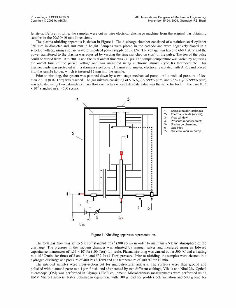
The plasma nitriding apparatus is shown in Figure 1. The discharge chamber consisted of a stainless steel cylinder 350 mm in diameter and 380 mm in height. Samples were placed in the cathode and were negatively biased in a selected voltage, using a square waveform pulsed power supply of 3.6 kW. The voltage was fixed to 660 ± 20 V and the power transferred to the plasma was adjusted by varying the time switched on (ton) of the pulse. The ton of the pulse could be varied from 10 to 200 s and the total on/off time was 240 s. The sample temperature was varied by adjusting the on/off time of the pulsed voltage and was measured using a chromel/alumel (type K) thermocouple. This thermocouple was protected with a stainless steel cover, 1.5 mm in diameter, electrically isolated with Al2O3 and placed into the sample holder, which is inserted 12 mm into the sample.
Prior to nitriding, the system was pumped down by a two-stage mechanical pump until a residual pressure of less than 2.6 Pa (0.02 Torr) was reached. The gas mixture consisting of 5 % N2 (99.999% pure) and 95 % H2 (99.999% pure) was adjusted using two datametrics mass flow controllers whose full scale value was the same for both, in the case 8.33 x 10⁻⁶ standard m3s-1 (500 sccm).
Figure 1. Nitriding apparatus representation.
The total gas flow was set to 5 x 10⁻⁶ standard m3s-1 (300 sccm) in order to maintain a ‘clean’ atmosphere of the discharge. The pressure in the vacuum chamber was adjusted by manual valves and measured using an Edward capacitance manometer of 1.33 x 10⁴ Pa (100 Torr) full scale. Plasma nitriding was carried out at 500 °C and a heating rate 15 °C/min, for times of 2 and 6 h, and 532 Pa (4 Torr) pressure. Prior to nitriding, the samples were cleaned in a hydrogen discharge at a pressure of 400 Pa (3 Torr) and at a temperature of 300 °C for 10 min.
The nitrided samples were cross-section cut for microstructural analysis. The surfaces were then ground and polished with diamond paste to a 1 m finish, and after etched by two different etchings, Vilella and Nital 2%. Optical microscope (OM) was performed in Olympus PME equipment. Microhardness measurements were performed using HMV Micro Hardness Tester Schimadzu equipment with 100 g load for profiles determination and 500 g load for
1- Sample holder (cathode); 2- Thermal shields (anode); 3- View window; 4- Pressure measurement; 5- Discharge chamber; 6- Gas inlet; 7- Outlet to vacuum pump.
Proceedings of COBEM 2009 20th International Congress of Mechanical Engineering Copyright © 2009 by ABCM November 15-20, 2009, Gramado, RS, Brazil
surface measurements. Additionally, X-ray diffractometry (XRD) analysis was performed on surfaces of nitrided samples, using a Shimadzu equipment, for = 1,54 nm copper tube.
The cavitation experiment was performed in agreement with ASTM G32/85 standard. This test consisted of specimen weight-loss partial determination as function of testing time. Cavitated region of each sample was characterized by Scanning Electronic Microscope (SEM) and X-ray diffraction.
3. RESULTS AND DISCUSSION
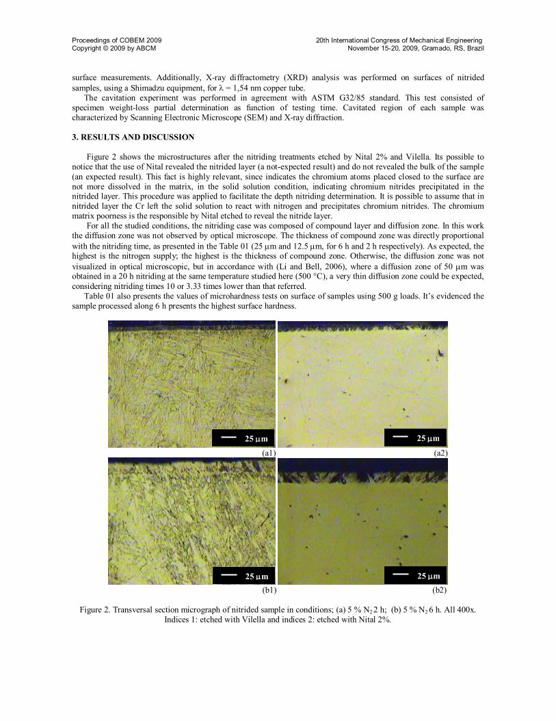
Figure 2 shows the microstructures after the nitriding treatments etched by Nital 2% and Vilella. Its possible to
notice that the use of Nital revealed the nitrided layer (a not-expected result) and do not revealed the bulk of the sample (an expected result). This fact is highly relevant, since indicates the chromium atoms placed closed to the surface are not more dissolved in the matrix, in the solid solution condition, indicating chromium nitrides precipitated in the nitrided layer. This procedure was applied to facilitate the depth nitriding determination. It is possible to assume that in nitrided layer the Cr left the solid solution to react with nitrogen and precipitates chromium nitrides. The chromium matrix poorness is the responsible by Nital etched to reveal the nitride layer.
For all the studied conditions, the nitriding case was composed of compound layer and diffusion zone. In this work the diffusion zone was not observed by optical microscope. The thickness of compound zone was directly proportional with the nitriding time, as presented in the Table 01 (25 m and 12.5 m, for 6 h and 2 h respectively). As expected, the highest is the nitrogen supply; the highest is the thickness of compound zone. Otherwise, the diffusion zone was not visualized in optical microscopic, but in accordance with (Li and Bell, 2006), where a diffusion zone of 50 m was obtained in a 20 h nitriding at the same temperature studied here (500 °C), a very thin diffusion zone could be expected, considering nitriding times 10 or 3.33 times lower than that referred.
Table 01 also presents the values of microhardness tests on surface of samples using 500 g loads. It’s evidenced the sample processed along 6 h presents the highest surface hardness.
(a1) (a2)
(b1) (b2)
Figure 2. Transversal section micrograph of nitrided sample in conditions; (a) 5 % N2 2 h; (b) 5 % N2 6 h. All 400x. Indices 1: etched with Vilella and indices 2: etched with Nital 2%.
25 m 25 m
25 m 25 m
Proceedings of COBEM 2009 20th International Congress of Mechanical Engineering Copyright © 2009 by ABCM November 15-20, 2009, Gramado, RS, Brazil
Table 01. Compound zone thickness and the respectably hardness values of the nitriding condition.
Nitriding Condition Thickness of compound zone (m) Vickers Hardness (HV0,5) 5 % N2 - 6 h 25 1173 5 % N2 - 2 h 12,5 950 Not-nitrided - 250
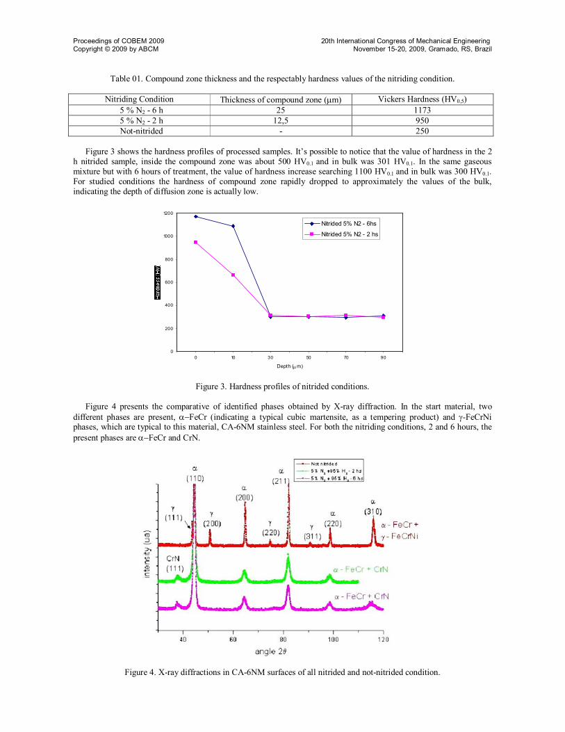
Figure 3 shows the hardness profiles of processed samples. It’s possible to notice that the value of hardness in the 2
h nitrided sample, inside the compound zone was about 500 HV0.1 and in bulk was 301 HV0.1. In the same gaseous mixture but with 6 hours of treatment, the value of hardness increase searching 1100 HV0.1 and in bulk was 300 HV0.1. For studied conditions the hardness of compound zone rapidly dropped to approximately the values of the bulk, indicating the depth of diffusion zone is actually low.
0
200
400
600
800
1000
1200
0 10 30 50 70 90
Depth (m)
Nitrided 5% N2 - 6hs
Nitrided 5% N2 - 2 hs
Figure 3. Hardness profiles of nitrided conditions.
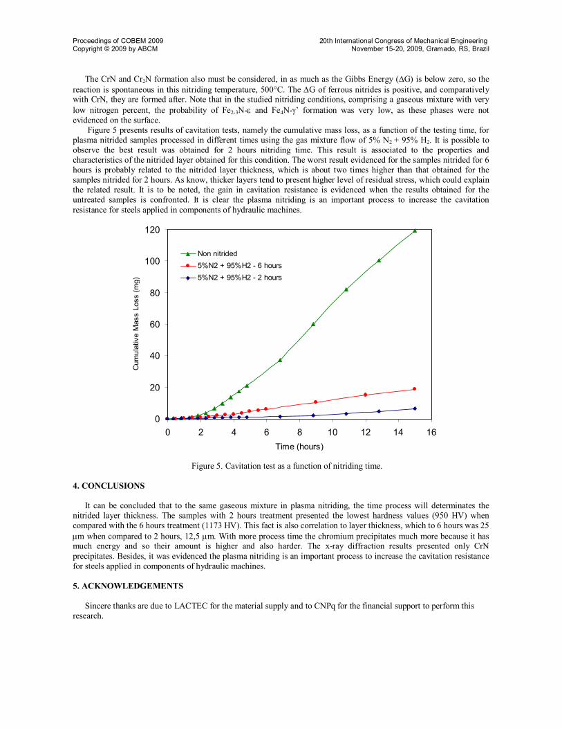
Figure 4 presents the comparative of identified phases obtained by X-ray diffraction. In the start material, two different phases are present, FeCr (indicating a typical cubic martensite, as a tempering product) and -FeCrNi phases, which are typical to this material, CA-6NM stainless steel. For both the nitriding conditions, 2 and 6 hours, the present phases are FeCrand CrN.
Figure 4. X-ray diffractions in CA-6NM surfaces of all nitrided and not-nitrided condition.
Proceedings of COBEM 2009 20th International Congress of Mechanical Engineering Copyright © 2009 by ABCM November 15-20, 2009, Gramado, RS, Brazil
The CrN and Cr2N formation also must be considered, in as much as the Gibbs Energy (G) is below zero, so the reaction is spontaneous in this nitriding temperature, 500°C. The G of ferrous nitrides is positive, and comparatively with CrN, they are formed after. Note that in the studied nitriding conditions, comprising a gaseous mixture with very low nitrogen percent, the probability of Fe2-3N- and Fe4N-’ formation was very low, as these phases were not evidenced on the surface.
Figure 5 presents results of cavitation tests, namely the cumulative mass loss, as a function of the testing time, for plasma nitrided samples processed in different times using the gas mixture flow of 5% N2 + 95% H2. It is possible to observe the best result was obtained for 2 hours nitriding time. This result is associated to the properties and characteristics of the nitrided layer obtained for this condition. The worst result evidenced for the samples nitrided for 6 hours is probably related to the nitrided layer thickness, which is about two times higher than that obtained for the samples nitrided for 2 hours. As know, thicker layers tend to present higher level of residual stress, which could explain the related result. It is to be noted, the gain in cavitation resistance is evidenced when the results obtained for the untreated samples is confronted. It is clear the plasma nitriding is an important process to increase the cavitation resistance for steels applied in components of hydraulic machines.
0
20
40
60
80
100
120
0 2 4 6 8 10 12 14 16Time (hours)
Cum
ulat
ive
Mas
s Lo
ss (m
g)
Non nitrided5%N2 + 95%H2 - 6 hours5%N2 + 95%H2 - 2 hours
Figure 5. Cavitation test as a function of nitriding time.
4. CONCLUSIONS
It can be concluded that to the same gaseous mixture in plasma nitriding, the time process will determinates the nitrided layer thickness. The samples with 2 hours treatment presented the lowest hardness values (950 HV) when compared with the 6 hours treatment (1173 HV). This fact is also correlation to layer thickness, which to 6 hours was 25 m when compared to 2 hours, 12,5 m. With more process time the chromium precipitates much more because it has much energy and so their amount is higher and also harder. The x-ray diffraction results presented only CrN precipitates. Besides, it was evidenced the plasma nitriding is an important process to increase the cavitation resistance for steels applied in components of hydraulic machines. 5. ACKNOWLEDGEMENTS
Sincere thanks are due to LACTEC for the material supply and to CNPq for the financial support to perform this research.
Proceedings of COBEM 2009 20th International Congress of Mechanical Engineering Copyright © 2009 by ABCM November 15-20, 2009, Gramado, RS, Brazil
6. REFERENCES Alphonsa, I., Chainani, A., Raole, P.M., Ganguli, B., John, P.I., 2001, “A Study of Martensitic Stainless Steel AISI 420
modified using plasma nitriding”, Institute for Plasma Research, Bhat, Gandhinagar, Elsevier, Gujarat, India, pp. 382-428.
Berg, M., Budtz-Jørgensen, C.V., Reitz, H., Schweitz, K.O., Chevallier, J., Kringhøj, P., et al, 2000, Surf. Coat. Technol, 124, pp. 25–31.
Bilmes, P.D.; Llorente, C.L.; Pérez I. J., 2000, “Toughness and microstructure of 13Cr4NiMo high strength steel welds”, Journal of Materials Engineering and Performance, 09, pp 609-615.
Crawford, J. D. CA-6NM an Update., 1974, “In; 29th Annual Steel Founder's Society of America Technical and Operating Conference”, pp. 1-13.
Edenhofer, B., 1974, “Heat Treatment Metals Part 1”, pp 23–28. Gooch, T. G., 1995, “Heat Treatment of Welding 13%Cr-4%Ni Martensitic Stainless Steel for Sour Service”, Welding
Research Supplement, pp 213-222. Jack, D. H., 1973, “Proceedings of the Heat Treatment”, Londony UK, pp. 39–50. Li, C.X., Bell, T., 2006, “Corrosion properties of plasma nitrided AISI 410 martensitic stainless steel in 3.5% NaCl and
1% HCl aqueous solutions”, Elsevier Corrosion Science 48, pp. 2036–2049. Lightfoot, J., Jack, D.H., 1973, “Proceedings of the Heat Treatment”, Londony UK, pp. 59–65. Pinedo, C., Monteiro, W., 2004, “On the kinetics of plasma nitriding a martensitic stainless steel type AISI 420”,
Elsevier, Surface and Coatings Technology 179, pp. 119–123. Rie. K.-T., 1999, Surf. Coat. Technol., 112, pp. 56–62. Sun. T., Bell. T., 1991, “Mater. Sci. Eng.” 140, pp. 419–434.


![Evaluation of cavitation erosion resistance of Al-Si ...€¦ · cavitation erosion models based on bulk mechanical properties [11-13] were performed in order to predict the erosion](https://static.fdocuments.net/doc/165x107/602fbc102d0fbb7b2944c54a/evaluation-of-cavitation-erosion-resistance-of-al-si-cavitation-erosion-models.jpg)


