L1: 6.111 Course Overview - MIT
27
L1: 6.111 Spring 2006 1 Introductory Digital Systems Laboratory L1: 6.111 Course Overview L1: 6.111 Course Overview Course Website: http://web.mit.edu/6.111/www/s2006/ Acknowledgements: Rex Min Some lecture material adapted from J. Rabaey, A. Chandrakasan, B. Nikolic, “Digital Integrated Circuits: A Design Perspective” Copyright 2003 Prentice Hall/Pearson.
Transcript of L1: 6.111 Course Overview - MIT

L1: 6.111 Spring 2006 1Introductory Digital Systems Laboratory
L1: 6.111 Course OverviewL1: 6.111 Course Overview
Course Website: http://web.mit.edu/6.111/www/s2006/
Acknowledgements:Rex Min
Some lecture material adapted from J. Rabaey, A. Chandrakasan, B. Nikolic, “Digital Integrated Circuits: A Design Perspective” Copyright 2003 Prentice Hall/Pearson.
L1: 6.111 Spring 2006 2Introductory Digital Systems Laboratory
6.111 Staff Contact Information6.111 Staff Contact Information
In-charge and LecturerProf. Anantha P. Chandrakasan – [email protected] (38-107, x8-7619)
Course Assistant: Margaret Flaherty – [email protected] (38-107, x3-0016)
Teaching Assistants (TAs) - x3-7350, office hours in 38-600Javier Castro ([email protected])Theodoros Konstantakopoulos ([email protected])Kyeong-Jae Lee ([email protected])
Lab Aides (LAs)Christopher Falling ([email protected]), Amir Hirsch ([email protected]), James J. Wnorowski ([email protected]), Yun Wu ([email protected])
Technical InstructorGim P. Hom ([email protected], Room 38-644, x4-3373)
Stock ClerkArlin Mason (lab kits) - [email protected] (38-600, x3-4674)John Sweeney (5th floor) - [email protected] (38-501, x3-0601)
L1: 6.111 Spring 2006 3Introductory Digital Systems Laboratory
Recommended BooksRecommended Books
Logic Design:Randy Katz, Gaetano Borriello, Contemporary Logic Design, Pearson Education, 2005
Verilog: there are plenty of good Verilog books and on-line resources. We recommend the book below for a basic introduction to Verilog:
Samir Palnitkar, Verilog HDL, Pearson Education (2nd edition)

L1: 6.111 Spring 2006 4Introductory Digital Systems Laboratory
6.111 Goals and Prerequisite6.111 Goals and Prerequisite
Design and Implement Complex Digital SystemsFundamentals of logic design : combinational and sequential blocksSystem integration with multiple components (memories, discrete components, FPGAs, etc.)Use a Hardware Design Language (Verilog) for digital designInterfacing issues with analog components (ADC, DAC, sensors, etc.)Understand different design metrics: component/gate count and implementation area, switching speed, energy dissipation and powerUnderstand different design methodologies and mapping strategies(discrete logic, FPGAs vs. custom integrated circuits)Design for test Demonstrate a large scale digital or mixed-signal system
PrerequisitePrior digital design experience is NOT Required6.004 is not a prerequisite!
Take 6.004 before 6.111 orTake 6.004 after 6.111 orTake both in the same term
Must have basic background in circuit theorySome basic material might be a review for those who have taken 6.004
L1: 6.111 Spring 2006 5Introductory Digital Systems Laboratory
Overview of LabsOverview of Labs
Lab 1: Basics of Digital Logic (Discrete Devices)Learn about lab equipment in the Digital Lab (38-600): oscilloscopes and logic analyzersExperiment with logic gates, flip-flops, device characterizationIntroduction to Verilog
Lab 2: Simple FSM (Traffic Light Controller)Design and implement simple Finite State Machines (FSM)Use Verilog to program an FPGAReport and its revision will be evaluated for CI-M
Lab 3: Simple FSM (Memory Tester)Learn how to use an SRAM and testing techniques
Lab 4: Complex FSM (Pong Game)Design a system with multiple FSMs (Major/Minor FSM)Video interface
L1: 6.111 Spring 2006 6Introductory Digital Systems Laboratory
Final ProjectFinal Project
Done in groups of two or three Open endedYou and the staff negotiate a project proposal
Must emphasize digital concepts, but inclusion of analog interfaces (e.g., data converters, sensors or motors) common and often desirableProposal ConferenceDesign Review(s)
Design presentation in class (% of the final grade for the in-class presentation)Top projects will be considered for design awardsStaff will provide help with project definition and scope, design, debugging, and testingIt is extremely difficult for a student to receive an A without completing the final project.
L1: 6.111 Spring 2006 7Introductory Digital Systems Laboratory
Grading and CollaborationGrading and Collaboration
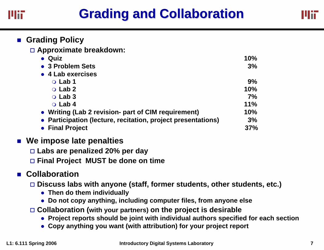
Grading PolicyApproximate breakdown:
Quiz 10%3 Problem Sets 3%4 Lab exercises
Lab 1 9%Lab 2 10%Lab 3 7%Lab 4 11%
Writing (Lab 2 revision- part of CIM requirement) 10%Participation (lecture, recitation, project presentations) 3%Final Project 37%
We impose late penaltiesLabs are penalized 20% per dayFinal Project MUST be done on time
CollaborationDiscuss labs with anyone (staff, former students, other students, etc.)
Then do them individuallyDo not copy anything, including computer files, from anyone else
Collaboration (with your partners) on the project is desirableProject reports should be joint with individual authors specified for each sectionCopy anything you want (with attribution) for your project report
L1: 6.111 Spring 2006 8Introductory Digital Systems Laboratory
The First ComputerThe First Computer
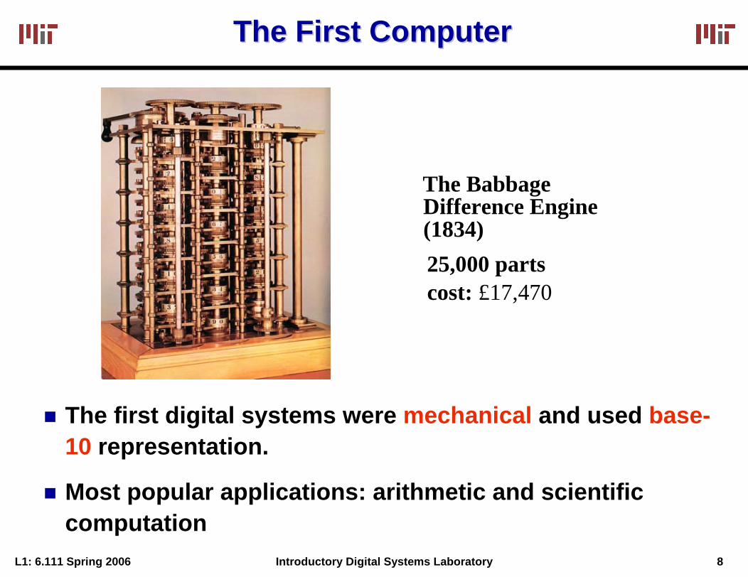
The BabbageDifference Engine(1834)25,000 partscost: £17,470
The first digital systems were mechanical and used base-10 representation.
Most popular applications: arithmetic and scientific computation
L1: 6.111 Spring 2006 9Introductory Digital Systems Laboratory
Meanwhile, in the World of TheoryMeanwhile, in the World of Theory……
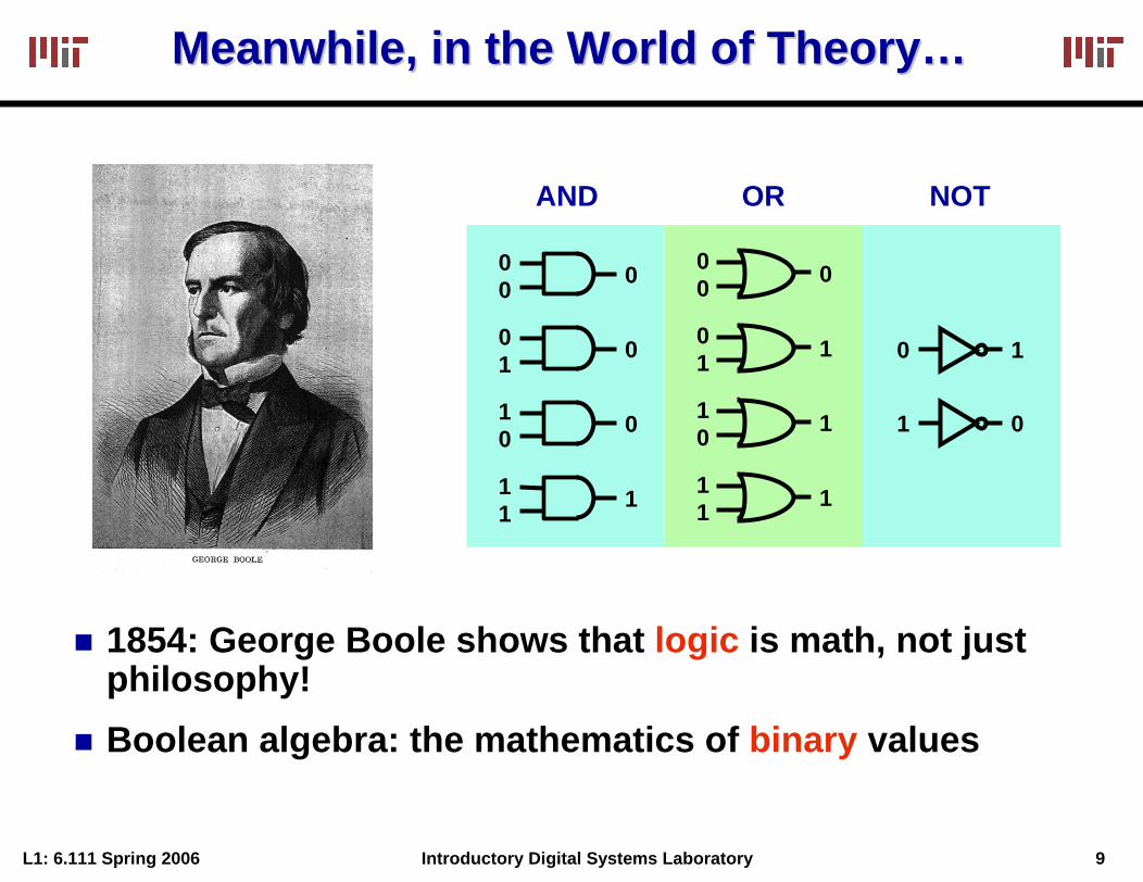
AND OR NOT
00 0
01 1
10 1
11 1
00 0
01 0
10 0
11 1
0 1
1 0
1854: George Boole shows that logic is math, not just philosophy!Boolean algebra: the mathematics of binary values
L1: 6.111 Spring 2006 10Introductory Digital Systems Laboratory
Key Link Between Logic and CircuitsKey Link Between Logic and Circuits
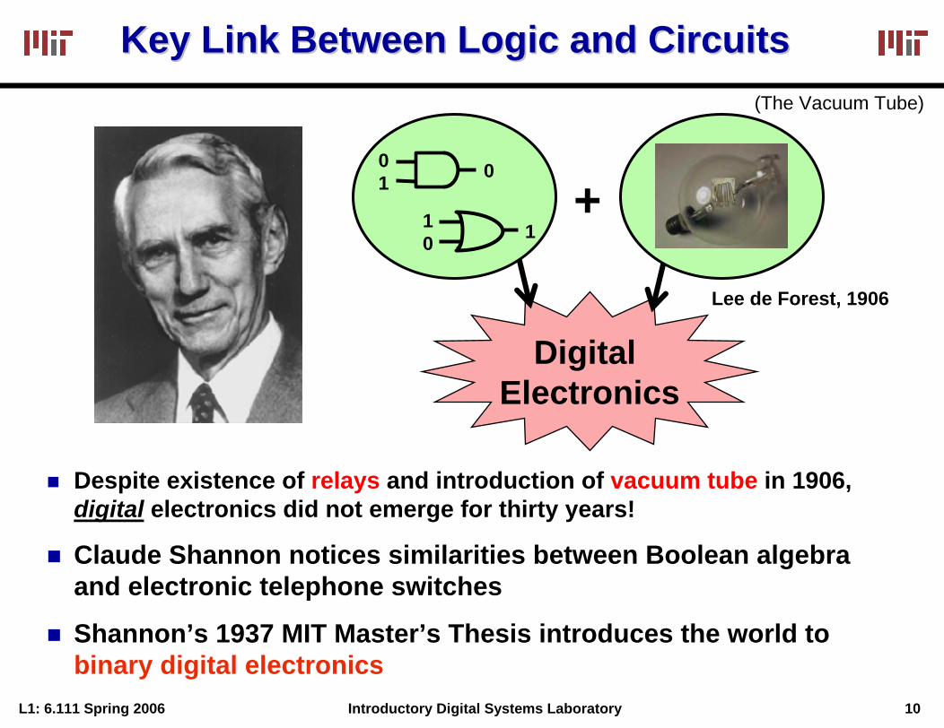
Digital Electronics
01 0
10 1
Lee de Forest, 1906
(The Vacuum Tube)
+
Despite existence of relays and introduction of vacuum tube in 1906, digital electronics did not emerge for thirty years!
Claude Shannon notices similarities between Boolean algebra and electronic telephone switches
Shannon’s 1937 MIT Master’s Thesis introduces the world to binary digital electronics
L1: 6.111 Spring 2006 11Introductory Digital Systems Laboratory
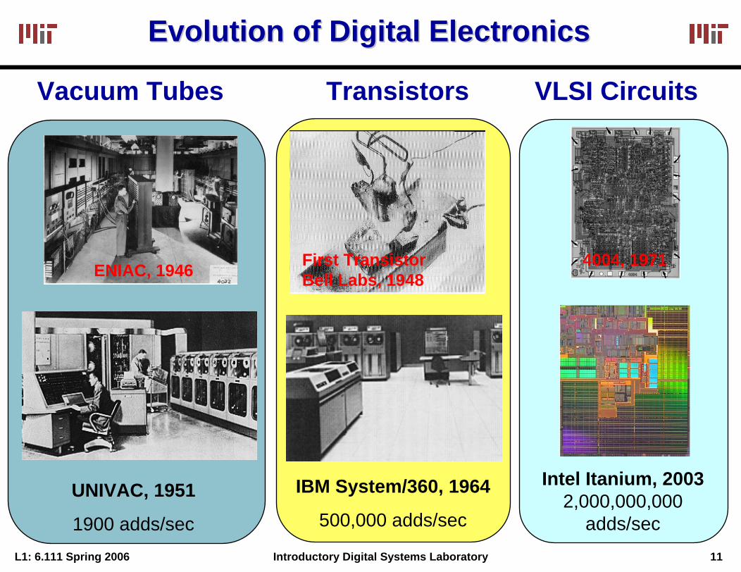
Evolution of Digital ElectronicsEvolution of Digital Electronics
Vacuum Tubes Transistors VLSI Circuits
4004, 1971First TransistorBell Labs, 1948ENIAC, 1946
Intel Itanium, 20032,000,000,000
adds/sec
IBM System/360, 1964
500,000 adds/secUNIVAC, 1951
1900 adds/sec
L1: 6.111 Spring 2006 12Introductory Digital Systems Laboratory
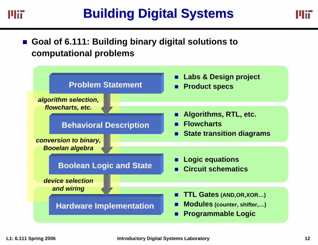
Building Digital SystemsBuilding Digital Systems
Goal of 6.111: Building binary digital solutions to computational problems
Hardware Implementation
Boolean Logic and State
Behavioral Description
conversion to binary,Booelan algebra
device selectionand wiring
algorithm selection,flowcharts, etc.
Problem StatementLabs & Design projectProduct specs
Algorithms, RTL, etc.FlowchartsState transition diagrams
Logic equationsCircuit schematics
TTL Gates (AND,OR,XOR…)Modules (counter, shifter,…)Programmable Logic

L1: 6.111 Spring 2006 13Introductory Digital Systems Laboratory
Building Digital Systems with Building Digital Systems with HDLsHDLs
Logic synthesis using a Hardware Description Language (HDL) automates the most tedious and error-prone aspects of design
Hardware Implementation
HDL Description
Behavioral Description
software-likeprogramming
automated synthesis
algorithm selection,flowcharts, etc.
Problem StatementLabs & Design projectProduct specs
Algorithms, RTL, etc.FlowchartsState transition diagrams
Verilog codeVHDL code
Programmable LogicCustom ASICs
L1: 6.111 Spring 2006 14Introductory Digital Systems Laboratory
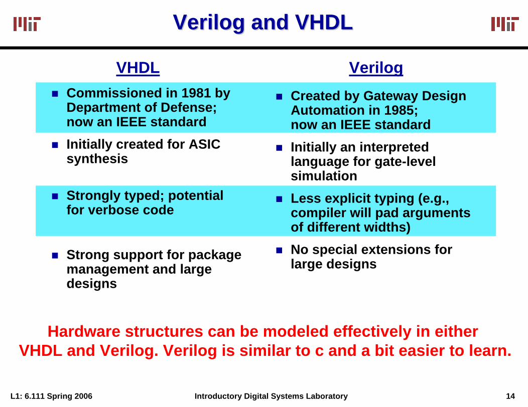
VerilogVerilog and VHDLand VHDL
Created by Gateway Design Automation in 1985; now an IEEE standardInitially an interpreted language for gate-level simulationLess explicit typing (e.g., compiler will pad arguments of different widths)No special extensions for large designs
Commissioned in 1981 by Department of Defense; now an IEEE standardInitially created for ASIC synthesis
Strongly typed; potential for verbose code
Strong support for package management and large designs
VHDL Verilog
Hardware structures can be modeled effectively in either VHDL and Verilog. Verilog is similar to c and a bit easier to learn.
L1: 6.111 Spring 2006 15Introductory Digital Systems Laboratory
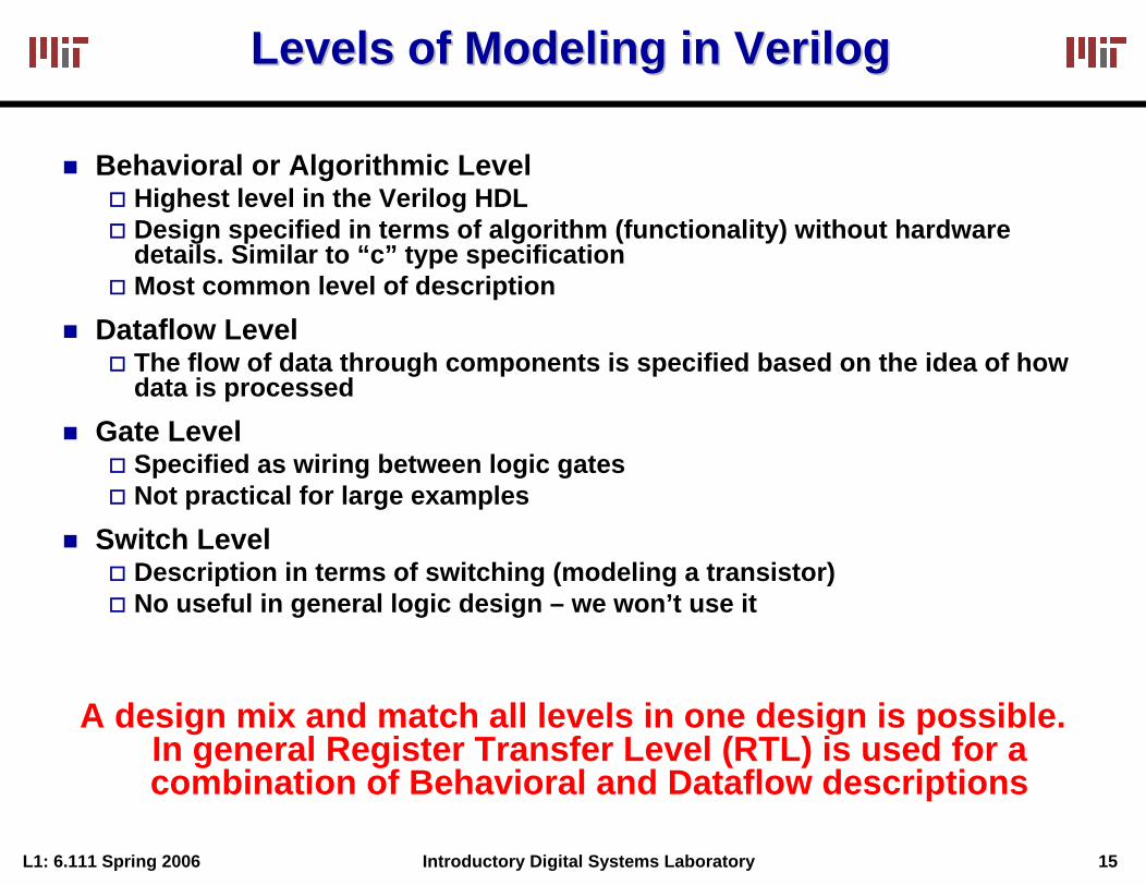
Levels of Modeling in Levels of Modeling in VerilogVerilog
Behavioral or Algorithmic LevelHighest level in the Verilog HDLDesign specified in terms of algorithm (functionality) without hardware details. Similar to “c” type specificationMost common level of description
Dataflow LevelThe flow of data through components is specified based on the idea of how data is processed
Gate LevelSpecified as wiring between logic gatesNot practical for large examples
Switch LevelDescription in terms of switching (modeling a transistor)No useful in general logic design – we won’t use it
A design mix and match all levels in one design is possible. In general Register Transfer Level (RTL) is used for a combination of Behavioral and Dataflow descriptions
L1: 6.111 Spring 2006 16Introductory Digital Systems Laboratory
VerilogVerilog HDLHDL
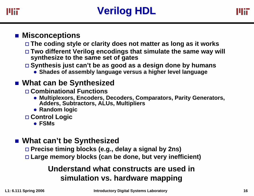
MisconceptionsThe coding style or clarity does not matter as long as it works Two different Verilog encodings that simulate the same way will synthesize to the same set of gatesSynthesis just can’t be as good as a design done by humans
Shades of assembly language versus a higher level language
What can be SynthesizedCombinational Functions
Multiplexors, Encoders, Decoders, Comparators, Parity Generators, Adders, Subtractors, ALUs, MultipliersRandom logic
Control LogicFSMs
What can’t be SynthesizedPrecise timing blocks (e.g., delay a signal by 2ns)Large memory blocks (can be done, but very inefficient)
Understand what constructs are used in simulation vs. hardware mapping
L1: 6.111 Spring 2006 17Introductory Digital Systems Laboratory
Embedded Digital SystemEmbedded Digital System
A/D
Sync.
digitize
synchronize
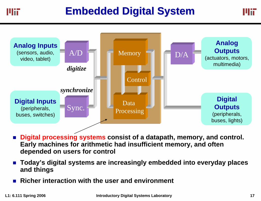
Digital processing systems consist of a datapath, memory, and control. Early machines for arithmetic had insufficient memory, and oftendepended on users for controlToday’s digital systems are increasingly embedded into everyday placesand thingsRicher interaction with the user and environment
Data Processing
Control
MemoryAnalog Inputs
(sensors, audio, video, tablet)
Digital Inputs(peripherals,
buses, switches)
D/A
DigitalOutputs
(peripherals,buses, lights)
Analog Outputs
(actuators, motors, multimedia)
L1: 6.111 Spring 2006 18Introductory Digital Systems Laboratory
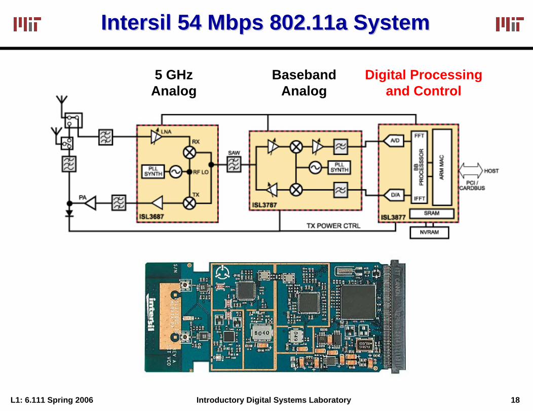
IntersilIntersil 54 Mbps 802.11a System54 Mbps 802.11a System
Digital Processingand Control
BasebandAnalog
5 GHzAnalog
L1: 6.111 Spring 2006 19Introductory Digital Systems Laboratory
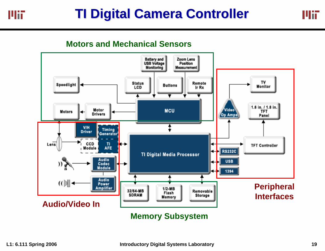
TI Digital Camera ControllerTI Digital Camera Controller
Motors and Mechanical Sensors
PeripheralInterfaces
Audio/Video InMemory Subsystem
L1: 6.111 Spring 2006 20Introductory Digital Systems Laboratory
RealReal--World Performance MetricsWorld Performance Metrics
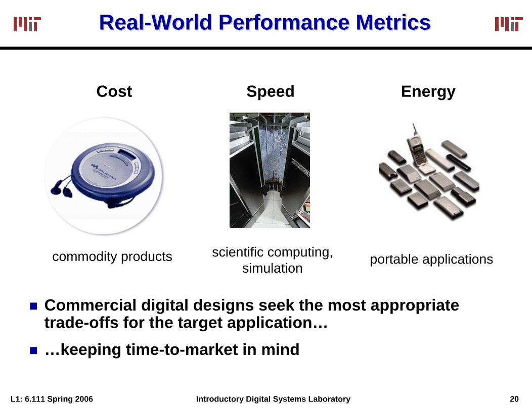
Cost Speed Energy
scientific computing,simulation
commodity products portable applications
Commercial digital designs seek the most appropriate trade-offs for the target application……keeping time-to-market in mind
L1: 6.111 Spring 2006 21Introductory Digital Systems Laboratory
Verification and TestingVerification and Testing
Design can be fun. Verification/testing is hard work.Verification by simulation (and formally through test benches) is a critical part of the design process.The physical hardware must be tested to debug the mapping process and manufacturing defects. Physical realizations often do not allow access to internal signals. We will introduce formal methods to observe and control internal state.
Verification and Design for Test (DFT) are important components of digital design

L1: 6.111 Spring 2006 22Introductory Digital Systems Laboratory
The Inverter: Voltage Transfer CharacteristicThe Inverter: Voltage Transfer Characteristic
Truth Table
VOH = f (VOL)VOL = f (VOH)VM = f (VM)
IN OUT IN OUT
0 1
1 0
Digital circuits perform operations on logical (or Boolean) variables
A logical variable is a mathematical abstraction. In a physical implementation, such a variable is represented by an electrical quantity
V(x)
V(y)
V OH
V OL
VM
V OHV OL
fV(y)=V(x)
(Switching Threshold)
Nominal Voltage Levels
L1: 6.111 Spring 2006 23Introductory Digital Systems Laboratory
Example Noise Sources in Digital CircuitsExample Noise Sources in Digital Circuits
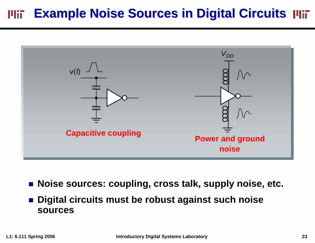
Capacitive coupling
v(t)
Power and groundnoise
VDD
Noise sources: coupling, cross talk, supply noise, etc.Digital circuits must be robust against such noise sources
L1: 6.111 Spring 2006 24Introductory Digital Systems Laboratory
The Inverter: Noise Margin The Inverter: Noise Margin
Truth TableIN OUT
0 1
1 0
IN OUT
"1"
"0"
VOHVIH
VILVOL
UndefinedRegion
V(x)VIHV
IL
Slope = -1
Slope = -1
VOLVOH
V(y)
VOH
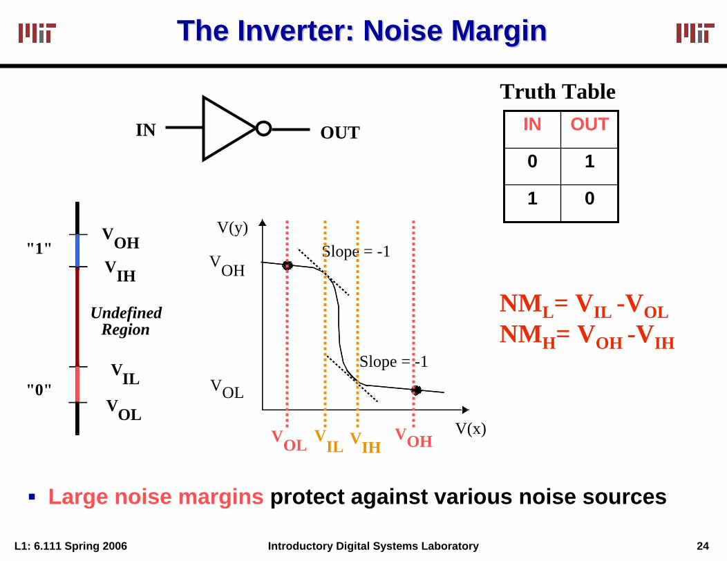
NML= VIL -VOLNMH= VOH -VIH
VOL
Large noise margins protect against various noise sources
L1: 6.111 Spring 2006 25Introductory Digital Systems Laboratory
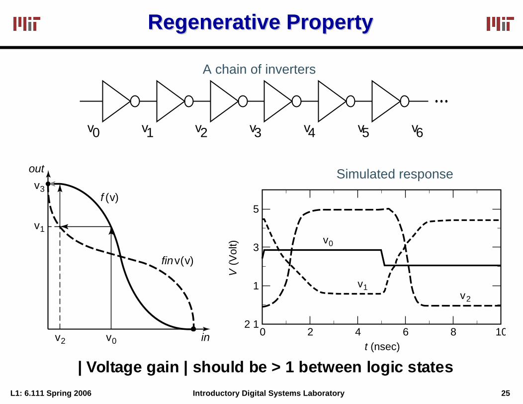
Regenerative PropertyRegenerative Property
A chain of inverters
v0 v1 v2 v3 v4 v5 v6
2
V (V
olt)
4
v0
v1v2
t (nsec)0
2 1
1
3
5
6 8 10
Simulated response
v2
v1
f (v)
finv(v)
v3
out
v0 in
| Voltage gain | should be > 1 between logic states
L1: 6.111 Spring 2006 26Introductory Digital Systems Laboratory
Lab Hours, Equipment, ComputersLab Hours, Equipment, Computers
The normal lab hours are (please be out by the indicated time):
Monday through Thursday – 9:00 AM to 11:45 PMFriday – 9:00 AM to 5:15 PMSaturday – CLOSEDSunday – noon to 11:45 PMHours for Holidays, Spring Break, etc. is posted on the course website
Please do not move or reconfigure computers and other lab equipment (logic analyzers, scopes, power supplies, etc.). Please turn off the power switch for the labkit when you are done for the day. Please report any equipment malfunctions (Logic Analyzers, Computers, labkit, etc.) by tagging such equipment. Also email [email protected] will use the following tools installed on the lab PCs (courtesy of Intel):
ModelSim (powerful front-end simulator for Verilog), Xilinx ISE (software for Xilinx FPGAs), Office (Microsoft word, power point, etc.)
You can use WinSCP to transfer files between the lab PCs and athenaUse a USB flash drive (provided with your kit) to save your workperiodicallyOn athena use ‘setup 6.111’- ‘setup 6.111’ sources /mit/6.111/.attachrc which attaches 6.111-nfs and sources /mit/6.111-nfs/.attachrc which sets up your path and environment variables, etc.
L1: 6.111 Spring 2006 27Introductory Digital Systems Laboratory
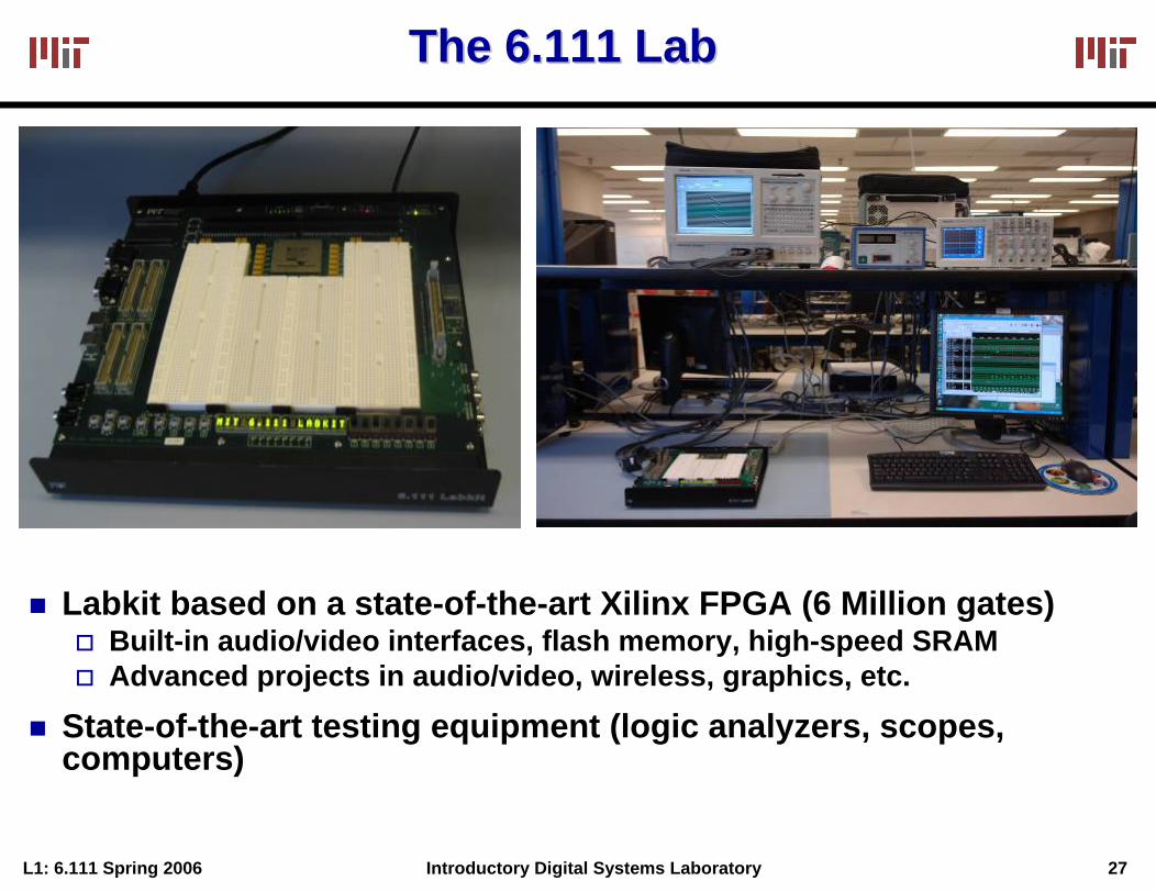
The 6.111 Lab The 6.111 Lab
Labkit based on a state-of-the-art Xilinx FPGA (6 Million gates)Built-in audio/video interfaces, flash memory, high-speed SRAMAdvanced projects in audio/video, wireless, graphics, etc.
State-of-the-art testing equipment (logic analyzers, scopes, computers)