KURUKSHETRA UNIVERSITYKURUKSHETRA Bachelor of …
39
KURUKSHETRA UNIVERSITYKURUKSHETRA Bachelor of Technology (Electrical Engineering) Scheme of Studies/Examination Semester-IV (w.e.f. Session 2019-20 onwards) * Subjects Common with IV Semester. B.Tech. [Electrical & Electronics Engg.] Scheme, K.U.K. **MC-902A is a mandatory credit-less course in which the students will be required to get passing marks in the major test. Note: All the students have to undergo 4 to 6 weeks Industrial Training after 4 th semester which will be evaluated in 5 th semester. Course No. Subject L:T:P Hours/ Week Credits Examination Schedule (Marks) Major Test Minor Test Practical Total EE-202A Digital Electronics 3:1:0 4 4 75 25 0 100 EE-204A Signals and Systems 3:1:0 4 4 75 25 0 100 *EE- 206A Electrical Machines – II 3:1:0 4 4 75 25 0 100 *EE-208A Power Electronics 3:1:0 4 4 75 25 0 100 EE-216A Electromagnetic Fields 3:0:0 3 3 75 25 0 100 *EE-210A Electrical Machines- II Lab 0:0:2 2 1 - 40 60 100 *EE-212A Power Electronics Lab 0:0:2 2 1 - 40 60 100 EE-214A Digital Electronics Laboratory 0:0:2 2 1 - 40 60 100 **MC-902A Constitution of India 3:0:0 3 - 100 - 0 100 Total 28 22 375 245 180 800
Transcript of KURUKSHETRA UNIVERSITYKURUKSHETRA Bachelor of …

KURUKSHETRA UNIVERSITYKURUKSHETRA Bachelor of Technology (Electrical Engineering)
Scheme of Studies/Examination Semester-IV (w.e.f. Session 2019-20 onwards)
* Subjects Common with IV Semester. B.Tech. [Electrical & Electronics Engg.] Scheme, K.U.K. **MC-902A is a mandatory credit-less course in which the students will be required to get passing marks in the major test.
Note: All the students have to undergo 4 to 6 weeks Industrial Training after 4thsemester which will be
evaluated in 5thsemester.
S. No.
Course No. Subject L:T:P Hours/ Week
Credits
Examination Schedule (Marks) Duration of Exam
(Hrs) Major Test
Minor Test
Practical Total
1 EE-202A Digital Electronics 3:1:0 4 4 75 25 0 100 3
2 EE-204A Signals and Systems 3:1:0 4 4 75 25 0 100 3
3 *EE- 206A Electrical Machines – II 3:1:0 4 4 75 25 0 100 3
4 *EE-208A Power Electronics 3:1:0 4 4 75 25 0 100 3
5 EE-216A Electromagnetic Fields 3:0:0 3 3 75 25 0 100 3
7 *EE-210A Electrical Machines- II Lab 0:0:2 2 1 - 40 60 100 3
8 *EE-212A Power Electronics Lab 0:0:2 2 1 - 40 60 100 3
9 EE-214A Digital Electronics Laboratory 0:0:2 2 1 - 40 60 100 3
10 **MC-902A Constitution of India 3:0:0 3 - 100 - 0 100 3
Total 28 22 375 245 180 800

EE-202A Digital Electronics 3L:0T:0P 3 credits
Course Outcomes: At the end of this course, students will demonstrate the ability to
Understand working of logic families and logicgates.
Design and implement Combinational and Sequentiallogic circuits.
Understand the process of Analog to Digital conversion and Digital to Analog conversion.
Be able to use PLDs to implement the given logicalproblem. Unit-I Fundamentals of Digital Techniques: Digital signal, review of number systems, binary codes, BCD, Excess-3, Gray, EBCDIC, ASCII, logic gates- AND, OR, NOT, NAND, NOR, EX-OR, Boolean algebra, Error detection and correction, hamming code.
Unit-II Combination Design using Gates: Design using gates, K- map and Quine-Mccluskey methods of simplification. Combinational design using MSI Devices Multiplexers and Demultiplexers and their uses as logic elements, Decoders, Adders/Subtracters, BCD arithmetic circuits, Encoders, Decoders/Drivers for display devices.
Unit-III Design of Sequential circuits: Flip flops: S-R, J-K, T,D, master slave, edge triggered, shift registers, sequence generators, counters- asynchronous and synchronous, ring counters and Johnson Counter. D/A &A/D Converters: D/A converters- weighted resistor and R-2 R ladder, specifications for D/A converters, A/D converters: Sample and hold circuits, Quantization, Parallel-comparator, successive approximation, counting type, dual slope ADC.
Unit-IV Digital logic families: Bipolar logic families: RTL, DTL, DCTL, HTL, TTL, ECL, MOS, and CMOS logic families. Tristate logic, interfacing of CMOS and TTL families. Programmable logic devices: ROM, PLA, PAL, FPGA and CPLDS. REFERENCES: 1. Modern Digital Electronics (Edition III) : R.P. Jain, TMH. 2. Digital Integrated Electronics: Taub& Schilling, MGH 3. Digital Principles and Applications: Malvino& Leach, MGH 4. Digital Fundamentals,Floyd,11thEd.,Pearson. Note: The paper setter will set the paper as per the question paper templates provided.

Lesson Plan
Name of Faculty: - Rajiv Sharma Discipline: - Electrical Engg.
Semester: - 4th
Subject: - Digital Electronics (EE-202A) Lesson Plan Duration: - 15 week
Work Load (Lecture/Practical):- Lecture=03, Tutorial=01, Practical=02
Week Theory Practical
Lecture
Day
Topic Practical
Day
Topic
1st 1. Introduction of subject and
review of basic terms
1
1) Study of TTL gates- AND,
OR, NOR, NAND, NOT,
EX-OR, EX-NOR.
2. Digital signal, logic gates, AND,
OR, NOT, NAND, NOR, EX-OR
3. Boolean algebra
2nd 4. Binary codes
2
Design & realize a given
function using K-Map and
verify its performance.
5. BCD
6. Excess-3
3rd 7. Gray, EBCDIC, ASCII
3
2) To verify the operation of
multiplexer &
Demultiplexers.
8. Error detection, Error correction
codes
9. UNIT Test
4th 10. Design using gates
4 3) To verify the operation of
comparator.
11. Karnaugh map
12. Quine-McCluskey methods of
simplification
5th 13. Quine-McCluskey methods of
simplification 5
4) To verify the truth tables
of S-R, J-K, T& D type flip
flops
14. Multiplexers
15. Demultiplexers, Encoders
6th 16. Decoders
6 5) To verify the operation of
bi-directional shift register.
17. Design of Half and Full Adder
18. Design of Half and Full
Subtractor, BCD arithmetic
circuits
7th 19. Drivers for display devices
7 Revision 20. Revision
21. Unit Test
8th 22. Sequential circuits: Flip flops: S-
R and J-K ,Flip flops: T and D
8
6) To design & verify the
operation of 3-bit
synchronous counter.
23. Flip flops: Master Slave and
Edge triggered
24. Sequence generators, Shift
Registers
9th 25. Counters : Asynchronous
counters 9
7) Design a 4-bit shift register
and verify its operation of a
ring counter and a Johnson
counter.
26. Synchronous counters
27. Ring counters, Johnson Counter

10th 28. D/A converters: weighted
resistor, R-2 R ladder network
10
To design and verify the
operation of asynchronous
UP/DOWN decade counter
using JK flip flop
29. specifications for D/A converters
30. A/D converters : Sample and
hold circuits
11th 31. Quantization, Parallel-comparator
11 Design Half Adder & Full
adder
32. Successive approximation, counting type
33. Dual Slope ADC, Specifications
of ADCs
12 34. Revision
12 Design Half Subtractor &
Full Subtractor 35. Unit Test
36. Bipolar logic families RTL, DTL, DCTL logic families
13 37. HTL logic families
13 To Study 4-Bit Comparator 38. TTL, ECL, MOS logic families
39. CMSO, Tristate logic families
14 40. interfacing of CMOS, TTL
14 Revision 41. ROM, PLA, PAL
42. FPGA
15 43. CPLDS
15 Revision 44. Revision
45. Unit Test
Tutorial Sheets
Unit-I
1. Express the following number in Binary, Octal & Hexadecimal.
i) (1947)10 (ii) (6725)10 (iii) (2421)10 (iv) (738)8 (v) (A7.F3)16
2. Convert the following binary to gray
(i) 10101 (ii) 110101 (iii) 1101011 (iv) 10110101
3. Reduce the following expressions using Boolean algebra:
(i) AB+A+ABC(AB+C) (ii) AB+ABC+A(B+AB)
(iii) A(B+C(AB+AC)) (iv) AB+AB+AB+AB
4. What is parity generator? Explain its working.
5. What is use of code converter? Design a code converter for binary to gray and gray to binary.
Unit-II
1. What does SOP means? Implement the expression: AB+BCD+EFGH using logic gates.
2. Reduce and implement in NOR logic.
F=∑m (0,2,3,5,7,9,11,12,13,14,15)
3. Reduce F=∑m (0, 2, 3, 5, 7) using mapping.
4. What is POS method of Boolean expression?
5. Describe difference between half adder and full adder.
6. What is the function of comparator? How it works?
7. Describe function of decoder. Design a 4 to 16 line decoder.
8. Design an 8 to 3 encoder using binary inputs and outputs.
9. Discuss use of multiplexers in digital electronics.
10. Explain functioning of demultiplexers.
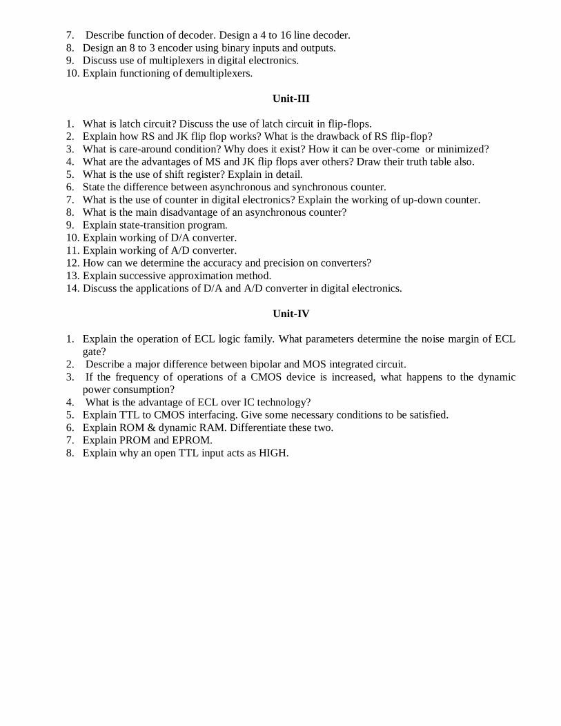
Unit-III
1. What is latch circuit? Discuss the use of latch circuit in flip-flops.
2. Explain how RS and JK flip flop works? What is the drawback of RS flip-flop?
3. What is care-around condition? Why does it exist? How it can be over-come or minimized?
4. What are the advantages of MS and JK flip flops aver others? Draw their truth table also.
5. What is the use of shift register? Explain in detail.
6. State the difference between asynchronous and synchronous counter.
7. What is the use of counter in digital electronics? Explain the working of up-down counter.
8. What is the main disadvantage of an asynchronous counter?
9. Explain state-transition program.
10. Explain working of D/A converter.
11. Explain working of A/D converter.
12. How can we determine the accuracy and precision on converters?
13. Explain successive approximation method.
14. Discuss the applications of D/A and A/D converter in digital electronics.
Unit-IV
1. Explain the operation of ECL logic family. What parameters determine the noise margin of ECL
gate?
2. Describe a major difference between bipolar and MOS integrated circuit.
3. If the frequency of operations of a CMOS device is increased, what happens to the dynamic
power consumption?
4. What is the advantage of ECL over IC technology?
5. Explain TTL to CMOS interfacing. Give some necessary conditions to be satisfied.
6. Explain ROM & dynamic RAM. Differentiate these two.
7. Explain PROM and EPROM.
8. Explain why an open TTL input acts as HIGH.


.
Course Outcomes: At the end of this course, students will demonstrate the ability to
Understand the concepts of continuous time and discrete timesystems.
Analyse systems in complex frequencydomain.
Understand sampling theorem and itsimplications.
Unit-I Introduction to Signals: Continuous and discrete time signals, deterministic and stochastic signals, periodic and aperiodic signals, even and odd signals, energy and power signals, exponential and sinusoidal signals and singular functions. Signal representation in terms of singular functions, Introduction to Systems: Linear and non-linear systems, time invariant and time varying systems ,lumped and distributed systems, deterministic and stochastic systems, casual and non-causal systems, analog and discrete/digital memory and memory less systems.
Unit-II Random Variables: Introduction to Random Variables, PDF, CDF Linear Time Invariant Systems: Introduction to linear time invariant (LTI) systems, properties of LTI systems, convolution integral, convolution sum, causal LTI systems described by differential and difference equations. Concept of impulse response.
Unit-III Discretization of Analog Signals: Introduction to sampling, sampling theorem and its proof. Effect of under sampling, reconstruction of a signal from sampled signal. Fourier Series :Continuous time Fourier series (CTFS), Properties of CTFS, Convergence of Fourier series.
Unit-IV Fourier Transform: Continuous Time Fourier Transform (CTFT), Properties of CTFT, Systems characterized by linear constant- coefficient differential equations. Discrete time Fourier transform (DTFT), Properties of DTFT, Duality, Systems characterized by linear constant coefficient difference equations. Laplace Transform: Introduction to Laplace transform, Region of convergence for laplace transform, Inverse Laplace transform, Properties of Laplace transform, Analysis and characterization of LTI systems using LaplaceTransform. REFERENCES : 1. Oppenheim, Willsky, Nawab, Signals and Systems, Prentice Hall India, 2nd Edition, 2009 2. Simon Haykins – “Signal & Systems”, Wiley Eastern 3. Tarun Kumar Rawat, Signals and Systems, Oxford University Press. Note: The paper setter will set the paper as per the question paper templates provided.
EE-204A Signals and Systems 2L:1T:0P 3 credits

Lesson Plan
Name of the teacher with designation: - Rishi Sarup Sharma (Assoc. Prof.) Department- Electrical Engg.
Subject : Signals & Systems ( 4th Semester), Computer Methods in power System (8th Semester) Lec
tur
e
Class Topic/Chapter covered Acad
emic
Activ
ity
Test
/
Assi
gnm
ent
1. 4thsem Introduction of subject and review of basic terms Lect.
2. 4thsem Different types of signals Lect.
3. 4thsem Periodic, impulse, singular functions Lect.
4. 4thsem Continuous and discrete time signals, deterministic and stochastic signals Lect.
5. 4thsem Periodic and aperiodic signals, even and odd signals, Lect.
6. 4thsem energy and power signals Lect.
7. 4thsem exponential and sinusoidal signals and singular functions. Lect.
8. 4thsem Signal representation in terms of singular functions. Lect.
9. 4thsem Linear and non-linear systems,
Lect.
19. 4thsem Time invariant and time varying systems Lect. Test
11. 4thsem Lumped and distributed , deterministic and stochastic systems Lect.
12. 4thsem Casual and non-causal systems Lect.
13. 4thsem Analog and discrete/digital memory and memory less systems. Lect.
14. 4thsem Introduction to Random Variables, PDF, CDF Lect.
15. 4thsem Introduction to linear time invariant (LTI) systems Lect.
16. 4thsem Properties of LTI systems Lect.
17. 4thsem Convolution integral, , convolution sum Lect.
18. 4thsem Causal LTI systems described by differential and difference equations. Lect. Test
19. 4thsem Concept of impulse response. Lect.
20. 4thsem Introduction to sampling, sampling theorem and its proof. Lect.
21. 4thsem Effect of under sampling, reconstruction of a signal from sampled signal. Lect.
22. 4thsem time Fourier series (CTFS) Lect.
23. 4thsem Properties of CTFS Lect.
24. 4thsem Convergence of Fourier series Lect.
25. 4thsem Continuous Time Fourier Transform (CTFT), Lect.
26. 4thsem Properties of CTFT Lect.
27. 4thsem Systems characterized by linear constant- coefficient differential equations.
Lect.
28. 4thsem Discrete time Fourier transform (DTFT) Lect. Test
29. 4thsem Properties of DTFT Lect.
30. 4thsem Duality Lect.
31. 4thsem Systems characterized by linear constant coefficient difference equations. Lect.
32. 4thsem Continuous Time Fourier Transform (CTFT), Lect.
33. 4thsem Introduction to Laplace transform, Properties of Laplace transform, Lect.
34. 4thsem Analysis and characterization of LTI systems using Laplace Transform. Lect.
35. 4thsem Region of convergence for Laplace transform, Inverse Laplace transform, Lect.
36. 4thsem Solution of University paper (Unit-I and II) Lect.
37. 4thsem Solution of University paper (Unit-III and IV) Lect. Test

Tute Sheets Unit-I
1. What are the basic operations on signals ? Discuss. 2. Examine whether following signals rae periodic or not?
a. X(t) = sin πt u(t) b. jej6t c. 3u(t) + 2 sin 2t d. 3 sin 200πt + 4 cos 100t 3. Determine the power and rms value of the signal x(t) = A sin (w0t + Ф) 4. Determine whether the following signals are time-invariant or not?
a. Y(t) = t2 x(t) b. y(n) = x2(n-2) c. y(t) = e2x(t) d. y(t) = x(t) sin 10 πt 5. Find whether the following systems are stable or not?
a. H(t) = (2+e-3t) u(t) b. y(t) = (t+5) u(t) c. h(t) = e2t u(t) d. h(t) = (1/RC) e-t/RC u(t) UNIT-II
1. A box contains 3 red, 4 white and 5 black balls. One ball is drawn at random . Find the probability that it is
A. Red B. not Black and C. Black or white
2. In an experiment =, three coins are tossed simultaneously. If the number of heads is the random variable, find the
probability function for this random variable.
3. What is meant by CDF? Give the properties of CDF.
4. The joint PDf of two random variables is expressed as FXY(x.y). If the random variable X and Y are statistically
independent, then show that fXY(x,y) = FX(x) FY(y)
Here fX(x) is the PDF of random variable X and fY(y) is the PDF of random variable Y.
5. The joint probability density function of two random variables X and Y is given as
FXY (x,y) = C(2x +y) for 0<x<2, O<y<3
= 0, elsewhere
Determine the value of constant C.
UNIT-III
1. State and explain the sampling theorem?
2. Explain the trigonometric Fourier series. What are its symmetric conditions?
3. Discuss the following properties of CTFS;
a. Time-shifting b. Frequency-shifting c . Convolution
4. Obtain the Fourier series representation of a periodic rectangular waveform.
5. Explain the concept of negative frequency.
Unit-IV
1. .Evaluate the fourier transform of a single-sided exponential function e-at u(t) .Draw its spectrum.
2. Find the Fourier transform of the Gate function.
3. State and prove the final value theorem.
4. Determine the Laplace transform of the square wave.
5. Evaluate the Laplace transform of the damped sine and cosine functions.


UNIT-I
Induction Machines: Basic concept of Induction machines: winding factors, generated e.m.f. and m.m.f distribution, a.c. winding, rotating magnetic field. 3-phase Induction Motor: Construction, features, production of torque, phasor diagram, equivalent circuit, performance analysis, torque -slip characteristics, running, light and blocked rotor test, load test on 3-ph I.M.
UNIT-II Single phase induction motors:- Constructional features & double revolving field theory, equivalent circuit, determination of parameters. Split phase, starting methods, types& applications. Starting of 3-ph I.M. Starting methods of squirrel cage and wound rotor induction motor. Induction Generator-Operation, applications, advantages.
UNIT-III Three Phase Synchronous Generators: Principle, construction, EMF equation, armature winding, armature reaction, equivalent circuit, voltage regulation - synchronous reactance method , Rothert’sm.m.f method, Potier triangle method, Output power equation, power angle curve, two reactance theory, slip test, Transient and subtransient reactance, synchronization, parallel operation.
UNIT-IV Three Phase Synchronous Motor: Construction, Principle of operation, Equivalent circuit, torque, power developed, starting, V-curve, Hunting-causes , effects & reduction , synchronous condenser applications. Comparison between induction motor and synchronous motor, high startig torque motors. Suggested Books: 1. A. E. Fitzgerald and C. Kingsley, "Electric Machinery”, McGraw Hill Education, 2013. 2. M. G. Say, “Performance and design of AC machines”, CBS Publishers, 2002. 3. P. S. Bimbhra, “Electrical Machinery”, Khanna Publishers, 2011. 4. I. J. Nagrath and D. P. Kothari, “Electric Machines”, McGraw Hill Education, 2010. 5. A. S. Langsdorf, “Alternating current machines”, McGraw Hill Education, 1984.
Note: The paper setter will set the paper as per the question paper templates provided.
EE-206A Electrical Machines-II
L T P Credit Major Test
Minor Test Total Time
3 1 - 4 75 25 100 3h
Purpose To familiarize the students with the basics of Electrical Machines
Course Outcomes
CO1 Understand the concepts of rotating magnetic fields.
CO 2 Understand the operation of ac machines.
CO 3 Analyse performance characteristics of ac machines.
CO 4 Analyse synchronous machine

LECTURE PLAN
LECTURES TOPICS
L1 Winding factor, generated e.m.f. and m.m.f. of distributed ac winding.
L2 Rotating magnetic field
L3 Effects of rotatings magnetic field
L4 Induction Machines : Constructional feature
L5 Production of torque, phasor diagram
L6 Equivalent circuit, performance analysis
L7 Torque slip characteristics.
L8 Testing - Light running, blocked rotor
L9 Load Test
L10 Effect of rotor resistance, deep bar induction motor
L11 Double cage Induction motor
L12 Generator operation
L13 Wound rotor induction motor
L14 Starting methods of squirrel cage
L15 Wound motor induction motor
L16 Introduction of space harmonics
L17 Effects of space harmonics
L18 Single phase induction motors : Constructional features
L19 Double field revolving theory
L20 Equivalent circuit.
L21 Determination of parameters
L22 Split phase starting methods
L23 Applications
L24 Synchronous Machine; - Construction
L25 Cylindrical rotor machine
L26 Alternator - e.m.f., circuit. model, phasor diagram
L27 Armature reaction, synchronous impedance
L28 Voltage regulation & different methods
L29 Synchronous motors- principle, circuit model, phase or diagram
L30 Effect of load
L31 Operating characteristics of machines, V-curves
L32 Starting methods of motor
L33 Salient pot machine - two reaction theory
L34 Phasor diagram/power angle characteristics
L35 Xd&Xq
L36 Parallel operation of alternator - Synchronization L37 Load division

Tute Sheets
UNIT -1
1. Explain generated EMF of distributed winding. 2. Explain MMF of distributed winding. 3. Explain the construction and working principle of 3 phase induction motor. 4. Draw and explain the Torque-speed charteristics of three phase induction motor. 5. On short circuit test, a 6 pole 50, HZ, 3 phase induction motor with stator resistance equal to
equivalent stand still rotor resistance, took 200A and 80Kw. Calculate the starting torque. 6. Discuss the points of similarities between a transformer and induction motor. Hence explain
why an induction machine, is a generalized transformer.
UNIT 2
1. Explain various methods of starting of squirrel cage and wound rotor Induction motor. 2. Write short notes on –
i. Generator operation
ii. Deep bar Induction motor
iii. Double cage Induction motor 3. Explain the Double field revolving theory of Single phase induction motor. 4. Explain the construction of Single phase Induction motor.
UNIT - 3
1. Explain the constructional feature of Synchronous generator. 2. Explain the parallel operation of Alternator. 3. Explain the MMF method or Potier Triangle method of voltage regulation. 4. Explain synchronizing the Alternator.
UNIT – 4
1. Explain why synchronous motor is not self-starting. 2. Explain the principle of operation of synchronous motor and effect of load on it. 3. Draw and explain the V-curves for synchronous motor. Compare the induction motor and
synchronous motor.


EE-208A Power Electronics
L T P Credit Major Test
Minor Test Total Time
3 - - 3 75 25 100 3h
Purpose To familiarize the students with the Converter and Power switching device
Course Outcomes
CO1 Understand the differences between signal level and power level devices.
CO 2 Analyse controlled rectifier circuits.
CO 3 Analyse the operation of DC-DC choppers.
CO 4 Analyse the operation of voltage source inverters.
UNIT-I Power switching devices : Diode, Thyristor, MOSFET, IGBT: I-V Characteristics; Firing circuit for thyristor; Voltage and current commutation of a thyristor; Gate drive circuits for MOSFET and IGBT.
UNIT-II Thyristor rectifiers Single-phase half-wave and full-wave rectifiers, Single-phase full-bridge thyristor rectifier with Rload and highly inductive load; Three-phase full-bridge thyristor rectifier with R-load and highly inductive load; Input current wave shape and power factor.
UNIT-III DC-DC buck converter: Elementary chopper with an active switch and diode, concepts of duty ratio and average voltage, power circuit of a buck converter, analysis and waveforms at steady state, duty ratio control of output voltage. DC-DC boost converter: Power circuit of a boost converter, analysis and waveforms at steady state, relation between duty ratio and average output voltage.
UNIT-IV Single-phase voltage source: Power circuit of single-phase voltage source inverter, switch states and instantaneous output voltage, square wave operation of the inverter, concept of average voltage over a switching cycle, bipolar sinusoidal modulation and unipolar sinusoidal modulation, modulation index and output voltage. Suggested Books: 1. M. H. Rashid, “Power electronics: circuits, devices, and applications”, Pearson Education India, 2009. 2. N. Mohan and T. M. Undeland, “Power Electronics: Converters, Applications and Design”, John Wiley & Sons,
2007. 3. R. W. Erickson and D. Maksimovic, “Fundamentals of Power Electronics”, Springer Science & Business
Media, 2007. 4. L. Umanand, “Power Electronics: Essentials and Applications”, Wiley India, 2009. Note: The paper setter will set the paper as per the question paper templates provided.

Lesson Plan Lecture
Day
Topic
1. Introduction
2. Diode
3. Thyristor 4. Numerical Practice
5. MOSFET
6. IGBT: I-V Characteristics
7. Firing circuit for thyristor
8. Numerical Practice
9. Voltage and current commutation of a thyristor
10. Voltage and current commutation of a thyristor
11. Gate drive circuits for MOSFET and IGBT
12. Numerical Practice
13. Gate drive circuits for MOSFET and IGBT
14. Revision
15. Test
16. Numerical Practice
17. Single-phase half-wave and full-wave rectifiers
18. Single-phase half-wave and full-wave rectifiers
19. Single-phase half-wave and full-wave rectifiers
20. Numerical Practice
21. Single-phase full-bridge thyristor rectifier with Rload and highly inductive load
22. Single-phase full-bridge thyristor rectifier with Rload and highly inductive load
23. Single-phase full-bridge thyristor rectifier with Rload and highly inductive load
24. Numerical Practice
25. Three-phase full-bridge thyristor rectifier with R-load and highly inductive load
26. Three-phase full-bridge thyristor rectifier with R-load and highly inductive load
27. Input current wave shape and power factor.
28. Numerical Practice
29. Revision
30. Test
31. Elementary chopper with an active switch and diode
32. Numerical Practice
33. Concepts of duty ratio and average voltage
34. Power circuit of a buck converter
35. Analysis and waveforms at steady state, duty ratio control of output voltage
36. Numerical Practice
37. Analysis and waveforms at steady state, duty ratio control of output voltage
38. Power circuit of a boost converter
39. Analysis and waveforms at steady state
40. Numerical Practice
41. Relation between duty ratio and average output voltage
42. Revision
43. Test
44. Numerical Practice
45. Power circuit of single-phase voltage source inverter 46. Switch states and instantaneous output voltage, square wave operation of the inverter
47. Switch states and instantaneous output voltage, square wave operation of the inverter
48. Numerical Practice
49. Concept of average voltage over a switching cycle
50. Bipolar sinusoidal modulation and unipolar sinusoidal modulation

51. Bipolar sinusoidal modulation and unipolar sinusoidal modulation
52. Numerical Practice
53. Modulation index and output voltage
54. Revision
55. Test
56. Numerical Practice
57. Revision
58. Revision
59. Revision
60. Test

Tutorial Sheet-1
Q1. Which is the Power semiconductor device having a) Highest switching speed; b) Highest voltage / current ratings; c) Easy drive features; d) Can be most effectively paralleled; e) Can be protected against over-currents with a fuse; f) Gate-turn off capability with regenerative features; g) Easy drive and High power handling capability Q2. An SCR requires 50 mA gate current to switch it on. It has a resistive load and is supplied from a 100 V DC supply. Specify the Pulse transformer details and the circuit following it, if the driver circuit supply voltage is 10 V and the gate-cathode drop is about 1 V. Q3. A Power BJT is used to switch an inductive load carrying 20 A. The supply voltage is 200V,
switching frequency and duty cycle are 1 KHZ and 0.5 respectively. Switching times are as follows. td
=
1μs, tri
= tfv1
= 8 μs, tfv2
= 0, ts = 12 μs, t
fi = t
rv2 = 8 μs, t
rv1 = 0. CEsatcV = 1.0V at i = 20 A
Calculate switching and conduction losses in the transistor. Q4. A thyristor has a maximum average current rating 1200 Amps for a conduction angle of 180°. Find the corresponding rating for Φ = 60°. Assume the current waveforms to be half cycle sine wave. Q5. Explain the effect of increasing the magnitude of the gate current and junction temperature on (i) forward and reverse break down voltages, (ii) forward and reverse leakage currents. Q6.
A MOSFET has the following parameters
VGS
(th) = 3V, gfs
= 3, CGS
= 800 PF, CGD
= 250 PF. The MOSFET is used to switch an inductive load of 15
Amps from 150V supply. The switching frequency is 50 kHz. The gate drive circuit has a driving voltage
of 15V and output resistance of 50Ω. Find out the switching loss in the MOSFET.
Q7. An IGBT is used to switch a resistive load of 5Ω from a DC supply of 350 volts as shown in the inset
of Fig 7.4 (a). The ON state gate voltage is vgE
= 15v. For the IGBT, vgE
(th) = 4 volts and gts
= 25. Find
out the maximum current flowing through the IGBT in the event of a short circuit fault across the load.
Also find out the power dissipation inside the device.
Q8. What is the role of dv/dt in operation of a thyristor? How can a high dv/dt cause an unwanted
trigerring? Discuss.
Q9. Draw and explain the trigerring circuits of a thyristor.
Q10. What is meant by commutation of SCR? Draw circuits and explain the methods for it.
Tutorial Sheet 2
Q1. Derive expressions for various performance indices of a controlled rectifier circuit.
Q2. A single phase fully controlled bridge converter operates in the continuous conduction mode
from a 230V, 50HZ single phase supply with a firing angle α = 30°. The load resistance and
inductances are 10Ω and 50mH respectively. Find out the 6th harmonic load current as a percentage
of the average load current.

Q3. A 220 V, 20A, 1500 RPM separately excited dc motor has an armature resistance of 0.75Ω and
inductance of 50mH. The motor is supplied from a 230V, 50Hz, single phase supply through a fully
controlled bridge converter. Find the no load speed of the motor and the speed of the motor at the
boundary between continuous and discontinuous modes when α = 25°.
Q4. Is it possible to operate a single phase fully controlled half wave converter in the inverting mode?
Explain.
Q5. A single phase half controlled converter is used to supply the field winding of a separately
excited dc machine. With the rated armature voltage the motor operates at the rated no load speed for
a fining angle α =0°. Find the value of α which will increase the motor no load speed by 30%.
Neglect lasses and saturation. Assume continuous conduction.
Q6.A single phase half controlled converter is used to boost the no load speed of a separately excited
dc machine by weakening its field supply. At α = 0° the half controlled converter produces the rated
field voltage. If the field inductance is large enough to make the field current almost ripple face what
will be the input power factor when the dc motor no load speed is bossed to 150%?
Q7. A three phase fully controlled bridge converter operating from a 3 phase 220 V, 50 Hz supply is
used to charge a battery bank with nominal voltage of 240 V. The battery bank has an internal
resistance of 0.01 Ω and the battery bank voltage varies by ± 10% around its nominal value between
fully charged and uncharged condition. Assuming continuous conduction find out. (i) The range of
firing angle of the converter. (ii) The range of ac input power factor. (iii) The range of charging
efficiency. When the battery bank is charged with a constant average charging current of 100 Amps
through a 250 mH lossless inductor.
Q8. A 220V, 750 RPM, 200A separately excited dc motor has an armature resistance of 0.05 Ω. The
armature is fed from a three phase non circulating current dual converter. If the forward converter
operates at a firing angle of 70º i) At what speed will the motor deliver rated torque. ii) What should
be the firing angle in the regenerative braking mode when the motor delivers half the rated torque at
600 rpm. Assume continuous conduction. Supply voltage is 400 V.
Q9. If a free wheeling diode is connected across the output terminals of a three phase fully controlled
converter will the performance of converter will be similar to a half controlled converter? Justify your
answer.
Q10. A battery with a nominal voltage of 200V and internal resistance of 10mΩ has to be charged at
a constant current of 20 amps from a 3 phase 220V 50 Hz power supply. Which of the following
converters will give better performance with respect to input current displacement factor, distortion
factor and power factor? (i) 3 phase fully controlled converter; (ii) 3 phase half controlled converter.
Tutorial Sheet – 3
Q1. A Chopper circuit is operating on TRC at a frequency of 2 kHz on a 460 V supply. If the load
voltage is 350 volts, calculate the conduction period of the thyristor in each cycle.
Q2. Input to the step up chopper is 200 V. The output required is 600 V. If the conducting time of
thyristor is 200 ssec. Compute Chopping frequency, If the pulse width is halved for constant
frequency of operation, find the new output voltage.

Q3. A dc chopper has a resistive load of and input voltage. When chopper is ON, its voltage drop is
1.5 volts and chopping frequency is 10 kHz. If the duty cycle is 80%, determine the average output
voltage and the chopper on time.
Q4. In a dc chopper, the average load current is 30 Amps, chopping frequency is 250 Hz. Supply
voltage is 110 volts. Calculate the ON and OFF periods of the chopper if the load resistance is 2
ohms.
Q5. Discuss the main classification of dc to dc thyristor converters. Which of these is more
commonly employed and why?
Q6. Describe the principle of step-up chopper. Derive an expression for the average output voltage in
terms of input dc voltage and duty cycle. State the assumptions made.
Tutorial Sheet – 4
Q1. A single phase half bridge inverter has a resistance of 2.5Ω and input DC voltage of 50V.
Calculate the following −RMS voltage occurring at the fundamental frequency, power Output, Peak current and average current, Harmonic RMS voltage and Total harmonic distortion. Q2. What are line-commutated inverters? How do they operate? Explain the difference between line-commutated and force-commutated inverters. Q3. What is the purpose of connecting diodesin antiparallel with thyristors in inverter circuits? Explain how these diodes come into play. Q4. Write Fourier series expression for the output voltages and currents obtained from single-phase half-bridge and full-bridge inverters. Q5. A single phase full bridge inverter is connected to an RL load. For a dc source voltage Vs and
output frequency f = 1/T, obtain expressions for load current and steady state current as a function of
time for the first two half cycles of the output voltage. For R = 20Ω and L = 0.1H, obtain the
expression for load current and steady state current, with source voltage 240V dc and frequency of
output voltage as 50 Hz.
Q6. A Single-phase bridge inverter is fed from 230Vdc. In the output voltage wave, only fundamental
component of voltage is considered. Determine the rms current ratings of an SCR and a diode of
bridge type loads: (i) R=2Ω and (ii) wL = 2Ω. Also, find the repetitive peak voltage that may appear
across the thyristor in part (i) and (ii).

Sample Paper Power Electronics (EE-208A)
MM. 75 Time: 3 Hours Note: Q1 and Q2 are compulsory. Attempt one question from each unit.
Q1 (a). Define holding and latching current of a thyristor. (b). What are the effects of firing angle on a converter? (c). What are the types of commutation? Define them also. (d). Explain the meaning of commutation and its types in regard to dc-dc choppers. (e). What is an inverter and its types? (3x5) Q2 (a). Explain the difference between power diode and signal diode. (b). What are the advantages of freewheeling diodes in a controlled in a controlled rectifier? (c). Discuss the advantages and disadvantages of Load Commutated Choppers. (d). Compare the methods of commutation used in bridge inverters. (5x4)
Unit 1
Q3. What is a thyristor? Give its constructional details. Describe different modes of operation of a thyristor with the help of its static V-I characteristics.Explain the need of commutation in thyristor circuits. What are the different methods of commutation schemes? (10) Q4. For an SCR, gate-cathode characteristic is given by Vg = 1 + 10Ig. Gate source voltage is a rectangular pulse of 15V with 20 µ sec duration. For an average gate power dissipation of 0.3W and peak gate drive power of 5W, compute (i) the resistance to be connected in series with SCR gate, (ii) the trigerring frequency, and, (iii) the duty cycle of the triggering pulse.(10)
Unit 2
Q5. A single-phase half-wave SCR circuit feeds power to a resistive load. Draw waveforms for source voltage, load voltage, load current and voltage across the SCR for a given firing angle of α. Hence obtain the expression for average and rms load voltages in terms of source voltage and firing angle. (10) Q6. Draw the circuit for a three-phase full convertor bridge with resistive load. Sketch the waveform for output voltage for a firing angle of 0o and overlap angle of 30o. Also, sketch thewaveform for output voltage for a firing angle of 30o and overlap angle of 30o. Indicate the conduction of various SCRs in these waveforms. (10)
Unit 3
Q7. Describe the operation of a dc chopper operation. Derive an expression for its average dc output voltage. Explain with appropriate waveforms, the different control strategies used for obtaining variable output voltage from a dc chopper. Which one of these is preferred over the other and why? (10) Q8. A chopper has the following data: T = 1000µs, R = 2Ω, L = 5mH. Find the duty cycle α, so that per unit value of minimum load current does not fall below, (i) 0.1 and (ii) 0.3 of Vs/R.(10)
Unit 4
Q9. Describe the working of a single phase half bridge inverter. What is its main drawback and how can it be overcome. (10) Q10. A single phase full bridge inverter is connected to an RL load. For a dc source voltage Vs and output frequency f = 1/T, obtain expressions for load current and steady state current as a function of time for the first two half cycles of the output voltage. For R = 20Ω and L = 0.1H, obtain the expression for load current and steady state current, with source voltage 240V dc and frequency of output voltage as 50 Hz. (10)

Unit-I
Review of Vector Calculus Vector algebra-addition, subtraction, components of vectors, scalar and vector multiplications, triple products, three orthogonal coordinate systems (rectangular, cylindrical and spherical). Vector calculus- differentiation, partial differentiation , integration, vector operat ordel, gradient, divergence and curl; integral theorems of vectors. Conversionofavectorfromonecoordinatesystemtoanother.
Unit-II Static Electric Field Coulomb’s law, Electric field intensity, Electrical field due to point charges. Line, Surface and Volume charge distributions. Gauss law and its applications. Absolute Electric potential, Potential difference, Calculation of potential differences for different configurations. Electric dipole, Electrostatic Energy and Energydensity.
Unit-III Conductors, Dielectrics and Capacitance Current and current density, Ohms Law in Point form, Continuity of current, Boundary conditions of perfect dielectric materials. Permittivity of dielectric materials, Capacitance, Capacitance of a two wire line, Poisson’s equation, Laplace’s equation, Solution of Laplace and Poisson’s equation, Application of Laplace’s and Poisson’s equations.
Unit-IV Static Magnetic Fields and Maxwell’s Equations: Biot-Savart Law, Ampere Law, Magnetic flux and magnetic flux density, Scalar and Vector Magnetic potentials. Steady magnetic fields produced by current carrying conductors. Nature of magnetic materials, Magnetization and permeability, Magnetic boundary conditions. Maxwell’s equations in differential and integral forms and their physical significances in circuit and field theory. Text / References:
1. M.N.O.Sadiku,“ElementsofElectromagnetics”,OxfordUniversityPublication,2014.
2. A.Pramanik,“Electromagnetism-Theoryandapplications”,PHILearningPvt.Ltd,New Delhi,2009. 3. A. Pramanik, “Electromagnetism-Problems with solution”, Prentice Hall India,2012.
EE-216A Electromagnetic Fields 3L:1T:0P 4 credits
Course Outcomes
At the end of the course, students will demonstrate the ability
To understand the basic laws ofelectromagnetism.
To obtain the electric and magnetic fields for simple configurations under static conditions.
To analyse time varying electric and magneticfields.
To understand Maxwell’s equation in different forms and differentmedia.
To understand the propagation of EMwaves. This course shall have Lectures and Tutorials. Most of the students find difficult to visualize electric and magnetic fields. Instructors may demonstrate various simulation tools to visualize electric and magnetic fields in practical devices like transformers, transmission lines and machines.

4. G. W. Carter, “The electromagnetic field in its engineering aspects”, Longmans,1954. 5. W.J.Duffin,“ElectricityandMagnetism”,McGrawHillPublication,1980. 6. W.J.Duffin,“AdvancedElectricityandMagnetism”,McGrawHill,1968.
7. E. G. Cullwick, “The Fundamentals of Electromagnetism” , Cambridge University Press, 1966. 8. B. D. Popovic, “Introductory Engineering Electromagnetics”, Addison-Wesley
Educational Publishers, International Edition,1971. 9. W. Hayt, “Engineering Electromagnetics”, McGraw Hill Education,2012.
Note: The paper setter will set the paper as per the question paper templates provided.
LIST OF EXPERIMENTS:
1) To perform load test on a 3-phase induction motor & DC generator set and to determine the efficiency of induction motor.
2) Determine mechanical losses by light running of a 3-phase induction motor. 3) Study and starting of 1-phase induction motor. To perform light running and block rotor test and to determine
the parameters of the equivalent circuit. 4) To perform the open circuit test and block rotor test on 3-phase induction motor and draw the circle diagram. 5) To perform & study effect of rotor resistance on a poly phase slip ring induction motor. 6)To calculate regulation by synchronous impedance method:- a) Conduct open and short circuit test on a three phase alternator. b) Determine and plot variation of synchronous impedance with If c) Determine SCR d) Determine regulations for 0.8 lagging power factor, 0.8 leading power factor and unity PF. 7) To plot V curves of a synchronous machine. a) Determination of Xo of a synchronous machine. b) Measurement Xd&Xq (Direct axis and Quardrature axis reactance) by slip test 8) To measure Xq of synchronous machine (negative sequence reactance). 9) To calculate regulation by ZPF method. 10) To perform and study parallel operation of synchronous generators. Note: At least eight experiments should be performed from above list.
EE -210A Electrical Machines Lab-II
L T P Credit Practical Minor Test Total Time
- - 2 1 60 40 100 3h

LIST OF EXPERIMENTS:
1. To Plot the firing characteristics of given silicon control rectifier. a. By varying the gate current Ig keeping forward voltage Vak fixed. b. By varying forward voltage Vak keeping gate current fixed. 2. To study the V-I characteristics of given UJT. To plot graph between Ve and Ie . To find
negative resistance from the graph. 3. To plot V-I characteristics of given Triac in I and III quadrant. 4. To plot the drain characteristics of given F.E.T & to evaluate the parameter rd, Idss. 5. To study the UJT based relaxation oscillator & to evaluate the dynamic resistance. 6. To study & draw the characteristics of DC-DC chopper power circuit 7. To study the characteristics of single phase fully controlled converter circuit. 8. To study the characteristics of 3-phase fully controlled converter power circuit. 9. To study single phase Mc Murray Inverter power circuit. 10. To study single phase cyclo-converter circuit. Note: At least eight experiments should be performed from above list.
EE -212A Power Electronics Lab
L T P Credit Practical Minor Test Total Time
- - 2 1 60 40 100 3h

LIST OF EXPERIMENTS: 1) Study of TTL gates- AND, OR, NOR, NAND, NOT, EX-OR, EX-NOR. 2) Design & realize a given function using K-Map and verify its performance. 3) To verify the operation of multiplexer & Demultiplexers. 4) To verify the operation of comparator. 5) To verify the truth tables of S-R, J-K, T& D type flip flops 6) To verify the operation of bi-directional shift register. 7) To design & verify the operation of 3-bit synchronous counter. 8) To design and verify the operation of synchronous UP/DOWN decade counter using JK flip flop & drive a
seven segment display using the same. 9) To design and verify the operation of asynchronous UP/DOWN decade counter using JK flip flop & drive a
seven segment display using the same. 10) To design and realize sequence generator for a given sequence using JK Flip flop. 11) Study of CMOS NAND & NOR gates and interfacing between TTL and CMOS gates. 12) Design a 4-bit shift register and verify its operation of a ring counter and a Johnson counter. Note: At least ten experiments should be performed from above list.
EEN -214A Digital Electronics Lab
L T P Credit Practical Minor Test Total Time
- - 2 1 60 40 100 3h

UNIT-I Meaning of the constitution law and constitutionalism, Historical perspective of the Constitution of India. Salient features and characteristics of the Constitution ofIndia. Scheme of the fundamentalrights
UNIT -II The scheme of the Fundamental Duties and its legal status. The Directive Principles of State Policy – Its importance and implementation. Federal structure and distribution of legislative and financial powers between the Union and theStates. Parliamentary Form of Government in India – The constitution powers and status of the President ofIndia
UNIT - III Amendment of the Constitutional Powers and Procedure. The historical perspectives of the constitutional amendments inIndia. Emergency Provisions: National Emergency, President Rule, Financial Emergency. Local Self Government – Constitutional Scheme inIndia.
UNIT-IV Scheme of the Fundamental Right to Equality. Scheme of the Fundamental Right to certain Freedom under Article19.Scope of the Right to Life and Personal Liberty under Article21.
Text Books
1. Constitution of India. Prof.Narender Kumar (2008) 8thedition. Allahabad LawAgency.
ReferenceBooks:
1. The constitution of India. P.M. Bakshi (2016) 15thEdition. Universal lawPublishing. Note: The paper setter will set the paper as per the question paper templates provided.
MC-902A Constitution of India
Lecture Tutorial Practical Major Test Minor Test Total Time
3 - - 75 25 100 3 Hrs.
Purpose To know the basic features of Constitution of India
Course Outcomes
CO1 The students will be able to know about salient features of the Constitution of India.
CO2 To know about fundamental duties and federal structure of Constitution of India.
CO3 To know about emergency provisions in Constitution of India.
CO4 To know about fundamental rights under constitution of India.

Week Lecture
Day
Class Topic/Chapter Covered Academic
Activity
Test/
Assignment
1st L1 B.Tech ELE- 4th
Semester Meaning of the constitution law and
constitutionalism
Lecture
L2 B.Tech ELE- 4th
Semester
Do Lecture
L3 B.Tech ELE- 4th
Semester
Do Lecture
2nd L4 B.Tech ELE- 4th
Semester
Historical perspective of the Constitution of India.
Lecture
L5 B.Tech ELE- 4th
Semester
Do Lecture
L6 B.Tech ELE- 4th
Semester
Do Lecture
3rd L7 B.Tech ELE- 4th
Semester
Salient features and characteristics of the Constitution of India.
Lecture
L8 B.Tech ELE- 4th
Semester
Do Lecture
L9 B.Tech ELE- 4th
Semester
Do Lecture
4th L10 B.Tech ELE- 4th
Semester
Scheme of the fundamental rights Lecture
L11 B.Tech ELE- 4th
Semester
Do Lecture
L12 B.Tech ELE- 4th
Semester
Do Lecture Assignment
from 1st Unit
5th L13 B.Tech ELE- 4th
Semester The scheme of the Fundamental Duties and its legal status.
Lecture
L14 B.Tech ELE- 4th
Semester
Do Lecture
L15 B.Tech ELE- 4th
Semester
Do Lecture
6th L16 B.Tech ELE- 4th
Semester The Directive Principles of State Policy – Its importance and implementation.
Lecture
L17 B.Tech ELE- 4th
Semester
Do Lecture
L18 B.Tech ELE- 4th
Semester
Do Lecture
7th L19 B.Tech ELE- 4th
Semester
Federal structure and distribution of legislative and financial powers between the Union and the States.
Lecture
L20 B.Tech ELE- 4th
Semester
Do Lecture
L21 B.Tech ELE- 4th
Semester
Do Lecture
8th L2 B.Tech ELE- 4th
Semester
Do Lecture

L22 B.Tech ELE- 4th
Semester
Parliamentary Form of Government in India – The constitution powers and status of the President of India
Lecture
L23 B.Tech ELE- 4th
Semester
Do Lecture
9th L24 B.Tech ELE- 4th
Semester
Do Lecture
L25 B.Tech ELE- 4th
Semester
Do Lecture Assignment
from 2nd unit
L26 B.Tech ELE- 4th
Semester Amendment of the Constitutional Powers
and Procedure. Lecture
10th L27 B.Tech ELE- 4th
Semester
Do Lecture
L28
B.Tech ELE- 4th
Semester
Do Lecture
L29
B.Tech ELE- 4th
Semester The historical perspectives of the constitutional amendments in India.
Lecture
11th L30
B.Tech ELE- 4th
Semester
Do Lecture
L31 B.Tech ELE- 4th
Semester
Do Lecture
L32 B.Tech ELE- 4th
Semester Emergency Provisions: National Emergency
Lecture
12th L33 B.Tech ELE- 4th
Semester
Do Lecture
L34 B.Tech ELE- 4th
Semester
President Rule Lecture
L35 B.Tech ELE- 4th
Semester
Do Lecture
13th L36 B.Tech ELE- 4th
Semester Financial Emergency. Lecture
L37
Add
On’s
B.Tech ELE- 4th
Semester
Do Lecture
L38
Add
On’s
B.Tech ELE- 4th
Semester
Do Lecture
14th L39
Add
On’s
B.Tech ELE- 4th
Semester
Local Self Government – Constitutional Scheme in India.
Lecture
L40
Add
On’s
B.Tech ELE- 4th
Semester
Do Lecture
L41
Add
On’s
B.Tech ELE- 4th
Semester
Do Lecture Assignment
from 3rdUnit

15th L42 B.Tech ELE- 4th
Semester
Scheme of the Fundamental Right to Equality.
Lecture
L43 B.Tech ELE- 4th
Semester
Do Lecture
L44 B.Tech ELE- 4th
Semester
Do Lecture
16th L45 B.Tech ELE- 4th
Semester Scheme of the Fundamental Right to
certain Freedom under Article 19. Lecture
L46 B.Tech ELE- 4th
Semester
Do Lecture
L47 B.Tech ELE- 4th
Semester
Do Lecture
L48 B.Tech ELE- 4th
Semester Scope of the Right to Life and Personal Liberty under Article 21.
Lecture
L49 B.Tech ELE- 4th
Semester
Do Lecture
L50 B.Tech ELE- 4th
Semester
Do Lecture
L51 B.Tech ELE- 4th
Semester
Do Lecture Assignment
from 4th Unit
Tutorial Sheet 1
1. Define constitution law.
2. What is constitutionalism?
3. Analyse the historical perspective of constitution of India in detail.
4. Discuss the salient features and characteristics of constitution of India.
5. Discuss the scheme of fundamental rights in constitution of India.
Tutorial Sheet 2
1. Discuss the scheme of fundamental duties and their legal status.
2. Explain the directive principles of state policy.
3. Discuss the importance and implementation of the directive principles of state policy.
4. Analyse the Federal structure and distribution of legislative power between union and the states.
5. Analyse the Federal structure and distribution of financial powers between the union and states.
6. Discuss the constitutional powers and status of president of India.
Tutorial Sheet 3
1. Analyse the amendment of constitutional power and procedure.
2. Discuss the historical perspectives of the constitutional amendment in India.
3. Examine the emergency provision in the constitutional scheme of India.
Tutorial Sheet 4
1. Discuss the scheme of fundamental rights to equality.

2. Elaborate the scheme of fundamental right to certain freedom under article 19.
3. Discuss the scope of right to life and personal liberty under article 21.
Sample Paper Constitution of India
MC-902 Time allowed: 3 Hours Maximum marks: 75 Note: The question paper carrys III parts, Part A & B is compulsory. Which is of 15 and 20 marks respectively. Part C is of 40 marks,attempt four questions by selecting at least one question from each unit.
Part A (5*3) = 15 Answer the following questions:
1. Define Constitutionalism.
2. Define characteristics of constitution of India.
3. List the scheme of fundamental rights.
4. List the fundamental duties.
5. Define president rule.
Part B (4*5) = 20 1. Discuss the historical perspective of constitution of India.
2. Discuss the federal structure and distribution of legislative and financial power between the union and the states.
3. Discuss the amendment of constitutional powers and procedures.
4. Analyse the scope of right to life and personal liberty under article 21.
Part C (4*10) = 40 Unit I
1. Discuss the salient features and characteristics of constitution of India.
2. Explain the scheme of fundamental rights in the constitution of India.
Unit II
1. Discuss the importance and implementations of directive principles of state policy.
2. Explain the parliamentary form of Govt. In India.
Unit III
1. Examine the amendments of constitutional powers and procedures in detail.
2. Discuss the emergency provisions: National , financial and presidential in detail.
Unit IV
1. Discuss the fundamental rights to equality.
2. Explain the scheme of fundamental rights to certain freedom under article 19.

Unit-I
Review of Vector Calculus Vector algebra-addition, subtraction, components of vectors, scalar and vector multiplications, triple products, three orthogonal coordinate systems (rectangular, cylindrical and spherical). Vector calculus- differentiation, partial differentiation , integration, vector operat ordel, gradient, divergence and curl; integral theorems of vectors. Conversion of a vector from one coordinate system to another.
Unit-II Static Electric Field Coulomb’s law, Electric field intensity, Electrical field due to point charges. Line, Surface and Volume charge distributions. Gauss law and its applications. Absolute Electric potential, Potential difference, Calculation of potential differences for different configurations. Electric dipole, Electrostatic Energy and Energydensity.
Unit-III Conductors, Dielectrics and Capacitance Current and current density, Ohms Law in Point form, Continuity of current, Boundary conditions of perfect dielectric materials. Permittivity of dielectric materials, Capacitance, Capacitance of a two wire line, Poisson’s equation, Laplace’s equation, Solution of Laplace and Poisson’s equation, Application of Laplace’s and Poisson’s equations.
Unit-IV Static Magnetic Fields and Maxwell’s Equations: Biot-Savart Law, Ampere Law, Magnetic flux and magnetic flux density, Scalar and Vector Magnetic potentials. Steady magnetic fields produced by current carrying conductors. Nature of magnetic materials, Magnetization and permeability, Magnetic boundary conditions. Maxwell’s equations in differential and integral forms and their physical significances in circuit and field theory. Text / References:
10. M.N.O.Sadiku,“ElementsofElectromagnetics”,OxfordUniversityPublication,2014. 11. A.Pramanik,“Electromagnetism-Theoryandapplications”,PHILearningPvt.Ltd,New Delhi,2009. 12. A. Pramanik, “Electromagnetism-Problems with solution”, Prentice Hall India,2012. 13. G. W. Carter, “The electromagnetic field in its engineering aspects”, Longmans,1954.
14. W.J.Duffin,“ElectricityandMagnetism”,McGrawHillPublication,1980. 15. W.J.Duffin,“AdvancedElectricityandMagnetism”,McGrawHill,1968.
16. E. G. Cullwick, “The Fundamentals of Electromagnetism” , Cambridge University Press, 1966. 17. B. D. Popovic, “Introductory Engineering Electromagnetics”, Addison-Wesley
Educational Publishers, International Edition,1971. 18. W. Hayt, “Engineering Electromagnetics”, McGraw Hill Education,2012.
Note: The paper setter will set the paper as per the question paper templates provided.
EE-216A Electromagnetic Fields 3L:1T:0P 4 credits
Course Outcomes
At the end of the course, students will demonstrate the ability
To understand the basic laws ofelectromagnetism.
To obtain the electric and magnetic fields for simple configurations under static conditions.
To analyse time varying electric and magneticfields.
To understand Maxwell’s equation in different forms and differentmedia.
To understand the propagation of EMwaves. This course shall have Lectures and Tutorials. Most of the students find difficult to visualize electric and magnetic fields. Instructors may demonstrate various simulation tools to visualize electric and magnetic fields in practical devices like transformers, transmission lines and machines.
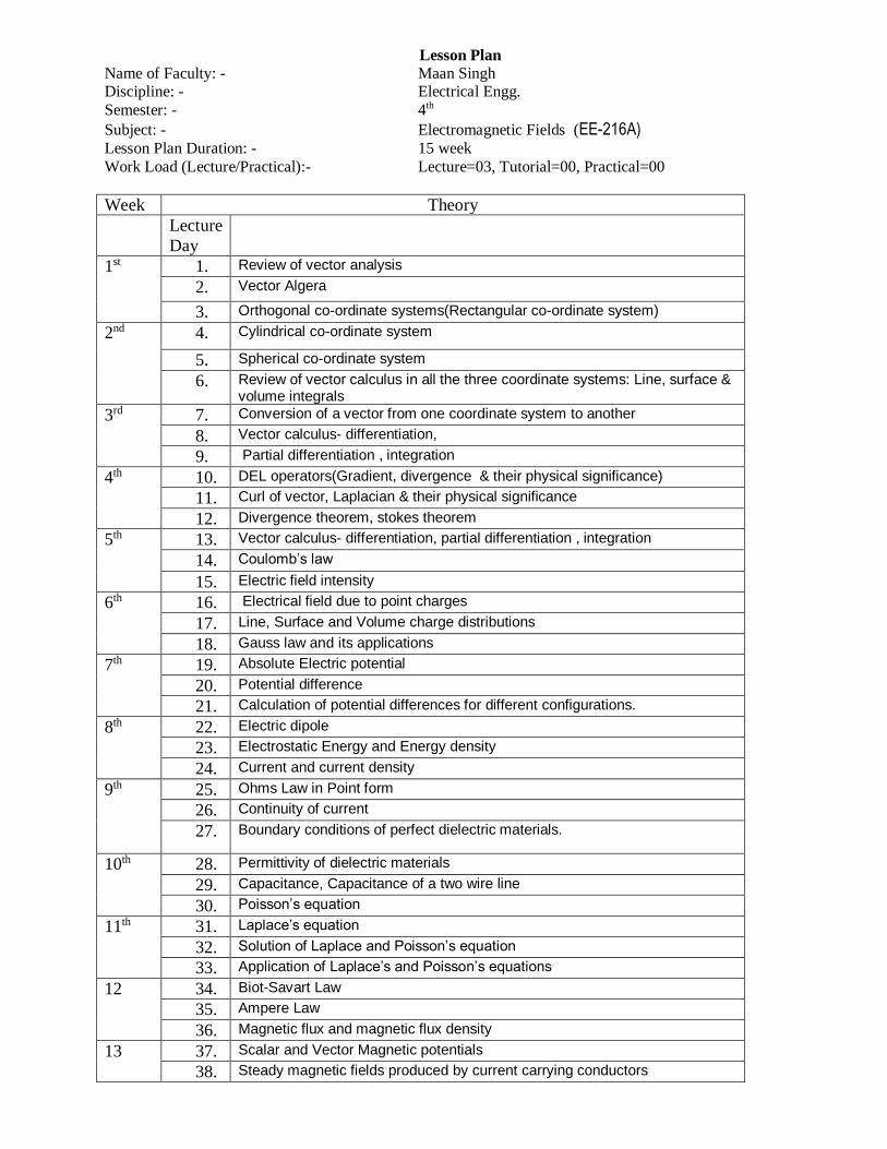
Lesson Plan
Name of Faculty: - Maan Singh Discipline: - Electrical Engg.
Semester: - 4th
Subject: - Electromagnetic Fields (EE-216A) Lesson Plan Duration: - 15 week
Work Load (Lecture/Practical):- Lecture=03, Tutorial=00, Practical=00
Week Theory
Lecture
Day
1st 1. Review of vector analysis
2. Vector Algera
3. Orthogonal co-ordinate systems(Rectangular co-ordinate system)
2nd 4. Cylindrical co-ordinate system
5. Spherical co-ordinate system
6. Review of vector calculus in all the three coordinate systems: Line, surface & volume integrals
3rd 7. Conversion of a vector from one coordinate system to another
8. Vector calculus- differentiation,
9. Partial differentiation , integration
4th 10. DEL operators(Gradient, divergence & their physical significance)
11. Curl of vector, Laplacian & their physical significance
12. Divergence theorem, stokes theorem
5th 13. Vector calculus- differentiation, partial differentiation , integration
14. Coulomb’s law
15. Electric field intensity
6th 16. Electrical field due to point charges
17. Line, Surface and Volume charge distributions
18. Gauss law and its applications
7th 19. Absolute Electric potential
20. Potential difference
21. Calculation of potential differences for different configurations.
8th 22. Electric dipole
23. Electrostatic Energy and Energy density
24. Current and current density
9th 25. Ohms Law in Point form
26. Continuity of current
27. Boundary conditions of perfect dielectric materials.
10th 28. Permittivity of dielectric materials
29. Capacitance, Capacitance of a two wire line
30. Poisson’s equation
11th 31. Laplace’s equation
32. Solution of Laplace and Poisson’s equation
33. Application of Laplace’s and Poisson’s equations
12 34. Biot-Savart Law
35. Ampere Law
36. Magnetic flux and magnetic flux density
13 37. Scalar and Vector Magnetic potentials
38. Steady magnetic fields produced by current carrying conductors

39. Nature of magnetic materials
14 40. Magnetization and permeability
41. Magnetic boundary conditions
42. Maxwell’s equations in differential forms and their physical significances in circuit and field theory
15 43. Maxwell’s equations in integral forms and their physical significances in circuit and field theory
44. Revision
45. Revision
TUTORIAL SHEET-1
1. State and prove Stoke’s theorem and also state significance of theorem.
2. State and explain Gauss law in electrostatics with applications.
3. Find the angle between A=101x + 21z and B=41x + 0.51z using both, dot and cross product. 4. Find the unit vector directed from (2,-5,2) toward (15,-5,3).
5. Discuss Gradient, divergence and curl and their physical significance.
TUTORIAL SHEET-2
1. State and proof gauss law .and explain applications of gauss law.
2. Drive an expression for the electric field due to a straight and infinite Uniformly charged wire
of length ‘L’ meters and with a charge density of + c/m at a point P which lies along the
perpendicular bisector of wire.
3. Derive the boundary conditions of the normal and tangential components of electric
field at the inter face of two media with different dielectrics.
4. Derive the boundary conditions of the normal and tangential components of electric field at
the inter face of two media with different dielectrics.
5. A uniform line charge L =25Nc/m lies on the x=3m and y=4m in free space . Find the electric
field intensity at a point (2,3,15)m.
TUTORIAL SHEET-3 1. The resistance of round long wire of diameter 3mm is 4.04 ohm/km.If current of 40 A flow through
the wire, find
(a) The conductivity of the wire and identify the material of the wire.
(b) The electric current density of the wire.
2. Determine the total current in the wire of radius 1.6mm if J=500az/ῤ A/m2. 3. Drive and Explain the Poisson’s Equation.
4. Drive and Explain the Laplace’s Equation.
5. Determine the capacitance of a conducting sphare of radius 5cm deeply immersed in sea water (ɛr=80). TUTORIAL SHEET-4
1. Explain Biot Savart’s Law.
2. Derive the expressions for boundary conditions in magnetic fields.
3. Derive the expression for torque developed in a rectangular closed circuit carrying current I a
uniform field.
4. Derive the expressions for magnetic flux intensity due to solenoid of the coil. 5. Write Maxwell’s equations in differential and integral form for free space.
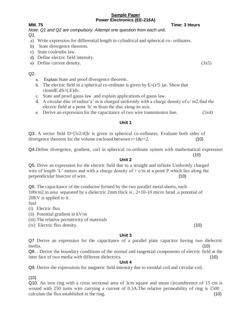
Sample Paper Power Electronics (EE-216A)
MM. 75 Time: 3 Hours Note: Q1 and Q2 are compulsory. Attempt one question from each unit. Q1.
a) Write expression for differential length in cylindrical and spherical co- ordinates.
b) State divergence theorem.
c) State coulombs law.
d) Define electric field intensity.
e) Define current density. (3x5)
Q2.
a. Explain State and proof divergence theorem.
b. The electric field in a spherical co-ordinate is given by E=(r/5 )ar. Show that
closedE.dS=(.E)dv.
c. State and proof gauss law .and explain applications of gauss law.
d. A circular disc of radius‘a’ m is charged uniformly with a charge density of c/ m2.find the electric field at a point ‘h’ m from the disc along its axis.
e. Derive an expression for the capacitance of two wire transmission line. (5x4)
Unit 1
Q3. A vector field D=[5r2/4]Ir is given in spherical co-ordinates. Evaluate both sides of
divergence theorem for the volume enclosed between r=1&r=2. (10)
Q4.Define divergence, gradient, curl in spherical co-ordinate system with mathematical expression (10)
Unit 2
Q5. Drive an expression for the electric field due to a straight and infinite Uniformly charged
wire of length ‘L’ meters and with a charge density of + c/m at a point P which lies along the perpendicular bisector of wire. (10)
Q6. The capacitance of the conductor formed by the two parallel metal sheets, each
100cm2,in area separated by a dielectric 2mm thick is , 2×10⁻¹⁰ micro farad .a potential of
20KV is applied to it .
find
(i) Electric flux
(ii) Potential gradient in kV/m
(iii) The relative permittivity of materials
(iv) Electric flux density. (10)
Unit 3
Q7 Derive an expression for the capacitance of a parallel plate capacitor having two dielectric
media. (10)
Q8. . Derive the boundary conditions of the normal and tangential components of electric field at the
inter face of two media with different dielectrics. (10)
Unit 4
Q9. Derive the expressions for magnetic field intensity due to toroidal coil and circular coil. (10)
Q10. An iron ring with a cross sectional area of 3cm square and mean circumference of 15 cm is
wound with 250 turns wire carrying a current of 0.3A.The relative permeability of ring is 1500 .
calculate the flux established in the ring. (10)