
Kristofer Gamstedt Presentation at CICY, Mérida, Mexico · Presentation at CICY, Mérida, Mexico...
42
15/10/2016 1 Cellulose-based nanocomposites Kristofer Gamstedt October 14, 2016 Presentation at CICY, Mérida, Mexico Uppsala University Stockholm Uppsala
-
Upload
dangkhuong -
Category
Documents
-
view
220 -
download
0
Transcript of Kristofer Gamstedt Presentation at CICY, Mérida, Mexico · Presentation at CICY, Mérida, Mexico...

15/10/2016
1
Cellulose-based nanocomposites
Kristofer Gamstedt
October 14, 2016
Presentation at CICY, Mérida, Mexico
Uppsala University
StockholmUppsala
15/10/2016
2
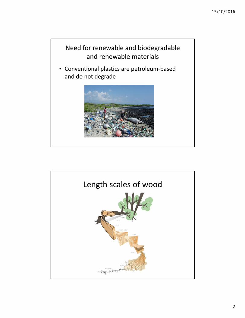
Need for renewable and biodegradable
and renewable materials
• Conventional plastics are petroleum-based
and do not degrade
Length scales of wood
15/10/2016
3
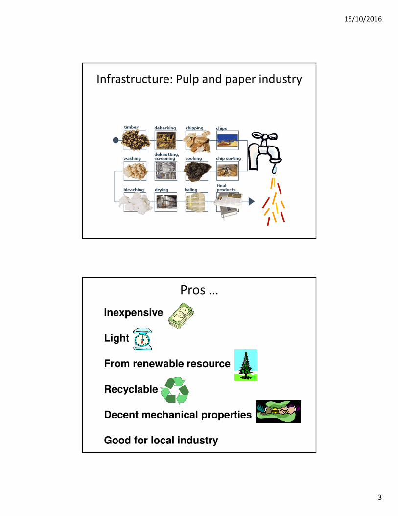
Infrastructure: Pulp and paper industry
Pros …
Inexpensive
Light
From renewable resource
Recyclable
Decent mechanical properties
Good for local industry
15/10/2016
4
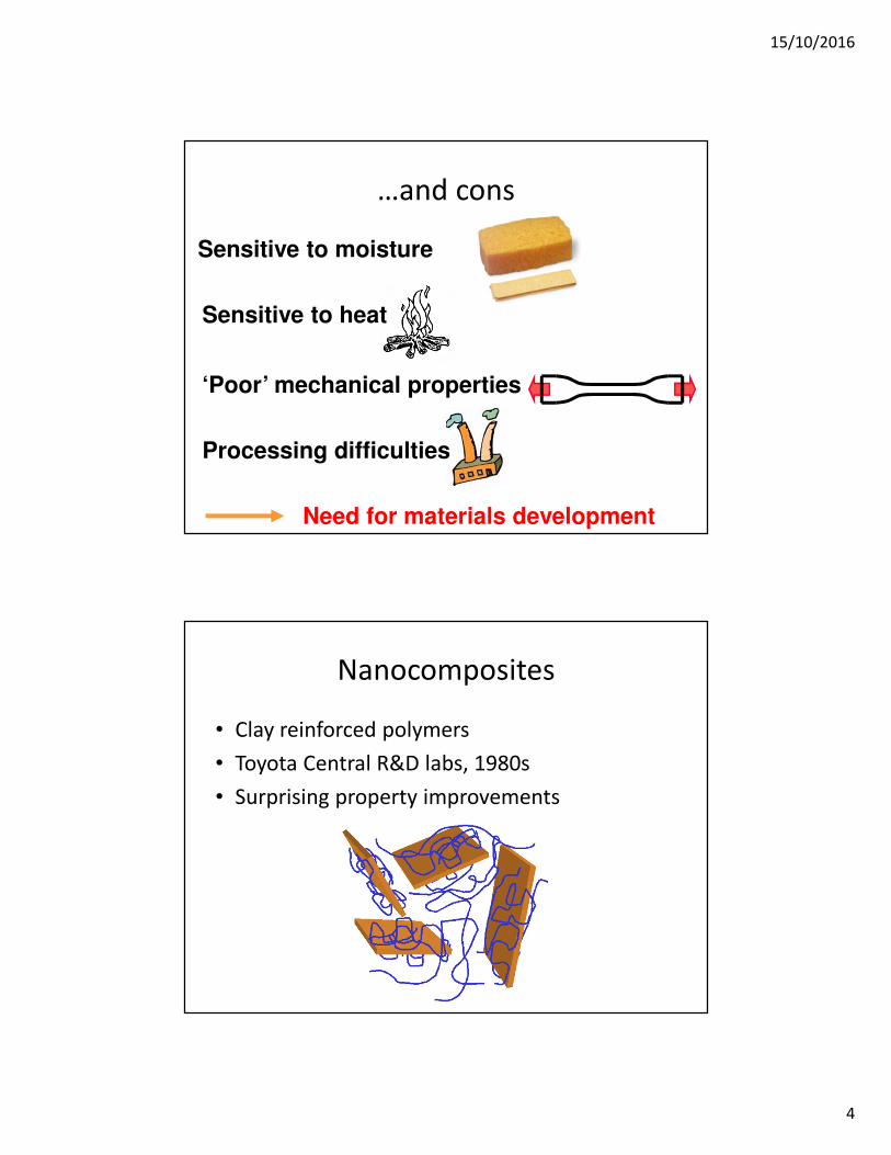
…and cons
Sensitive to heat
Processing difficulties
Need for materials development
Sensitive to moisture
‘Poor’ mechanical properties
Nanocomposites
• Clay reinforced polymers
• Toyota Central R&D labs, 1980s
• Surprising property improvements
15/10/2016
5
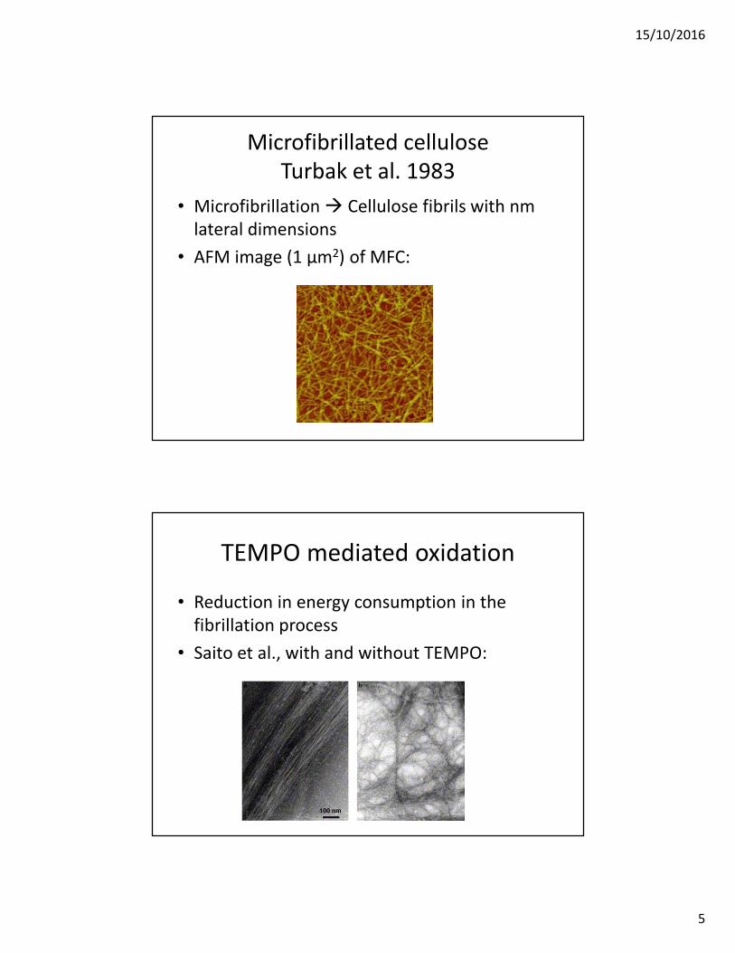
Microfibrillated cellulose
Turbak et al. 1983
• Microfibrillation Cellulose fibrils with nm
lateral dimensions
• AFM image (1 µm2) of MFC:
TEMPO mediated oxidation
• Reduction in energy consumption in the
fibrillation process
• Saito et al., with and without TEMPO:
15/10/2016
6
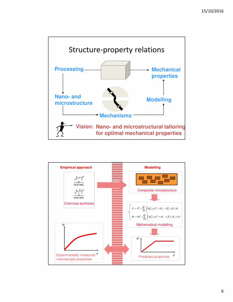
Structure-property relations
Processing Mechanicalproperties
Nano- and microstructure
Mechanisms
Modelling
Nano- and microstructural tailoringfor optimal mechanical properties
Vision:
Empirical approach Modelling
Chemical synthesis
OHO
OO
O
OO
OO
O
H
WOOD FIBRIL
WOOD FIBRIL
Experimentally measured macroscopic properties
ε
σ
Composite microstructure
∑ ∫=
−
−+′+=N
k
z
z
kkjjjkljll
k
k
zHzKQNN1
m0
1
d ))(()( βε
∑ ∫=
−
−+′+=N
k
z
z
kkjjjkljll
k
k
zzHzKQMM1
m0
1
d ))(()( βε
Mathematical modelling
Predicted properties ε
σ
15/10/2016
7
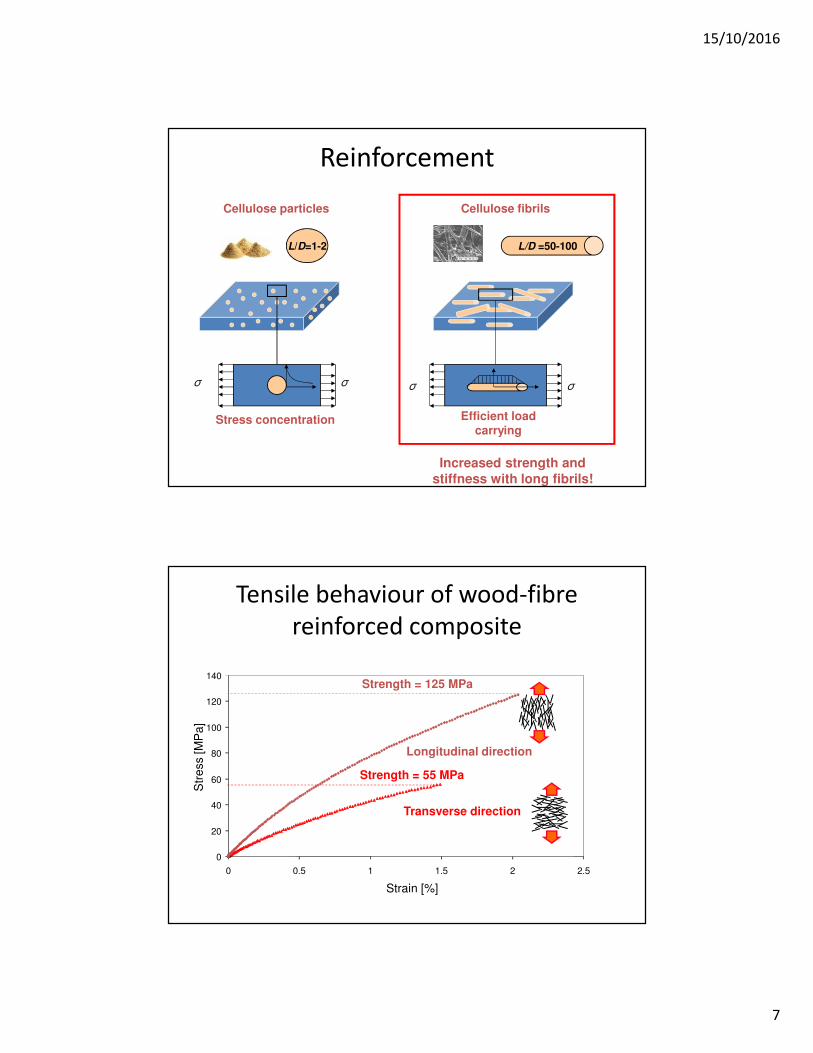
Reinforcement
L/D =50-100L/D=1-2
Cellulose particles Cellulose fibrils
σ σ σ σ
Stress concentration Efficient load carrying
Increased strength and stiffness with long fibrils!
0
20
40
60
80
100
120
140
0 0.5 1 1.5 2 2.5
Strain [%]
Str
ess [M
Pa
]
Transverse direction
Longitudinal direction
Strength = 55 MPa
Strength = 125 MPa
Tensile behaviour of wood-fibre
reinforced composite
15/10/2016
8
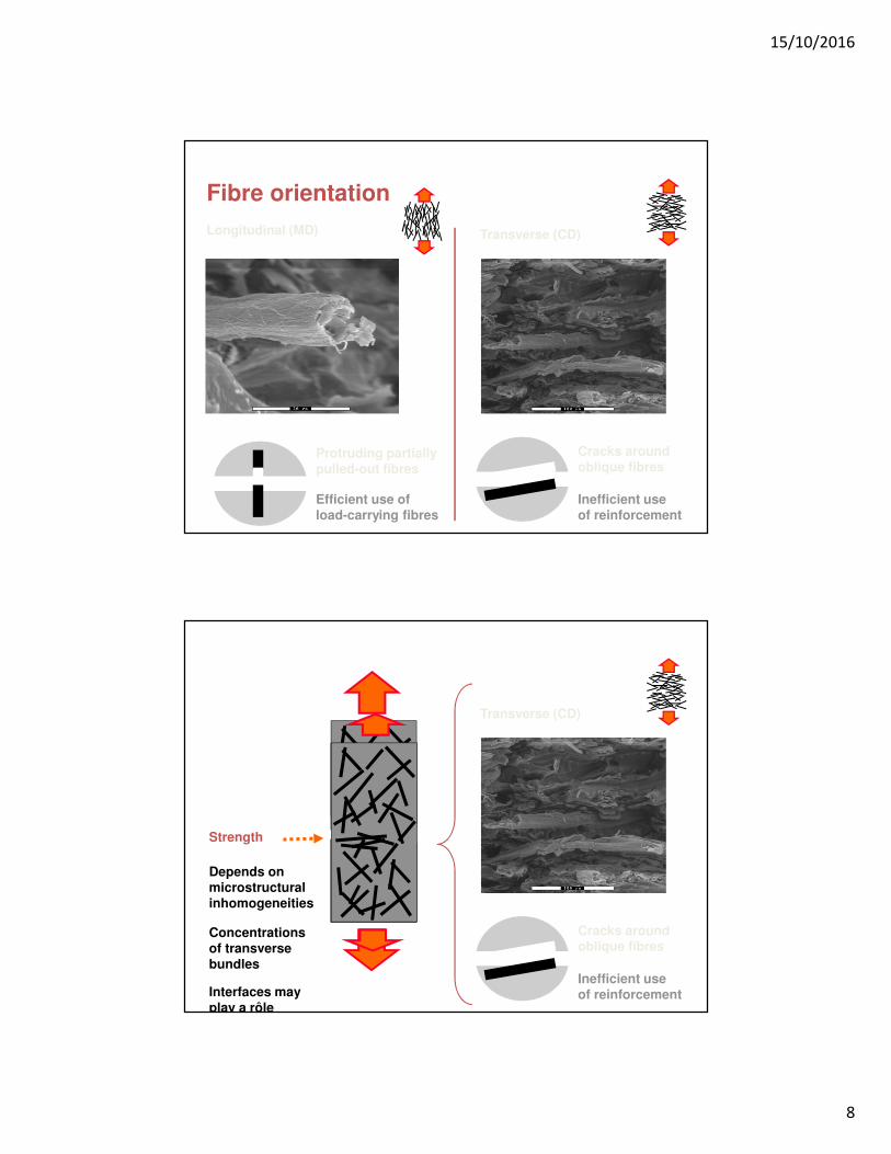
Fibre orientation
Longitudinal (MD) Transverse (CD)
Protruding partiallypulled-out fibres
Cracks aroundoblique fibres
Efficient use ofload-carrying fibres
Inefficient useof reinforcement
Transverse (CD)
Cracks aroundoblique fibres
Inefficient useof reinforcement
Strength
Depends onmicrostructuralinhomogeneities
Concentrationsof transversebundles
Interfaces mayplay a rôle

15/10/2016
9
Failed specimens
Failure at different locations
at microstructural ‘defects’
Empirical approachMechanism-based
approach
Improved materials development !
Micromechanics as a tool for quantitative materials design !
Tailoring of material structures
15/10/2016
10
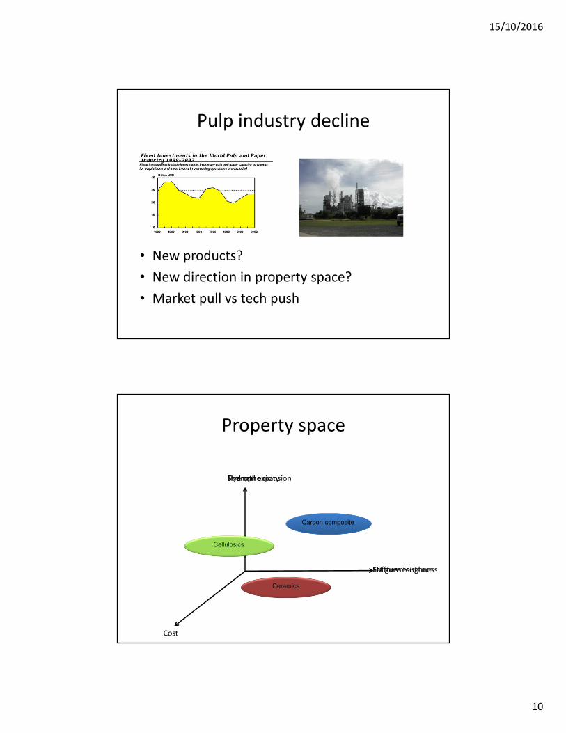
Pulp industry decline
• New products?
• New direction in property space?
• Market pull vs tech push
Property space
Carbon composite
Cellulosics
Ceramics
Hydrophobicity
Fracture toughness
Cost
Fatigue resistance
Themral expansionStrength
Stiffness
15/10/2016
11
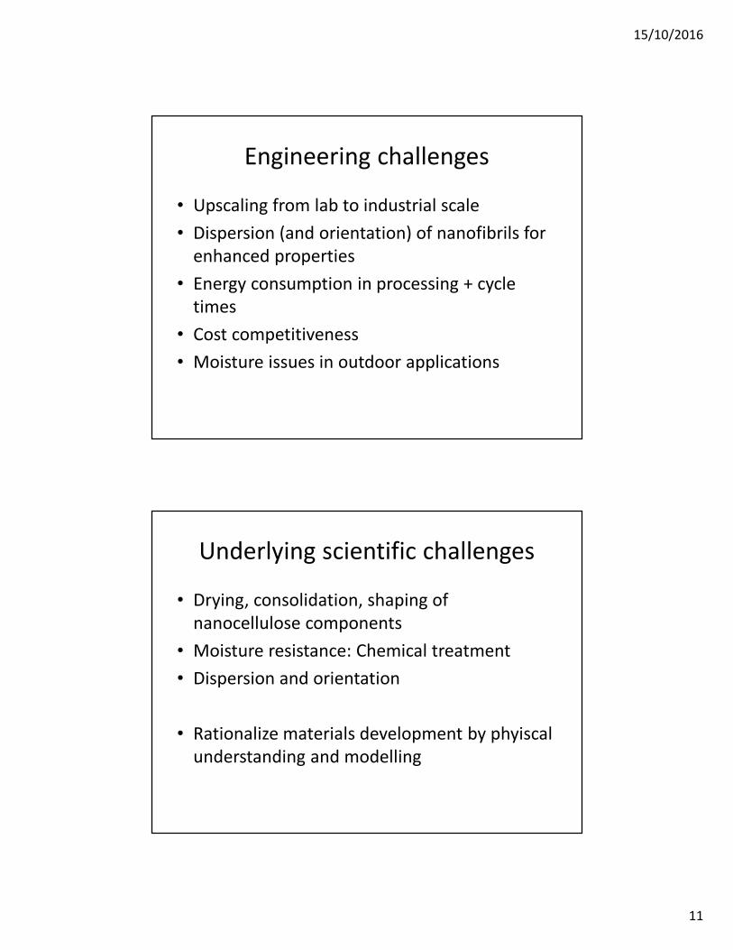
Engineering challenges
• Upscaling from lab to industrial scale
• Dispersion (and orientation) of nanofibrils for
enhanced properties
• Energy consumption in processing + cycle
times
• Cost competitiveness
• Moisture issues in outdoor applications
Underlying scientific challenges
• Drying, consolidation, shaping of
nanocellulose components
• Moisture resistance: Chemical treatment
• Dispersion and orientation
• Rationalize materials development by phyiscal
understanding and modelling
15/10/2016
12
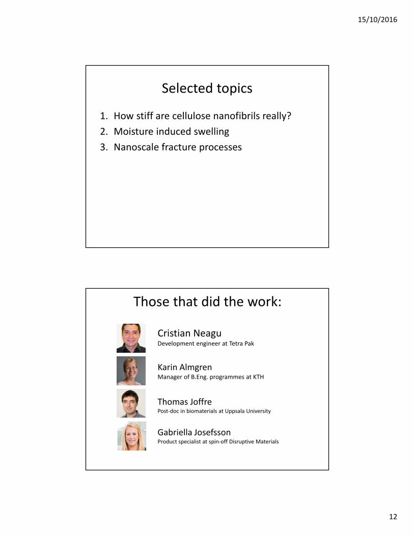
Selected topics
1. How stiff are cellulose nanofibrils really?
2. Moisture induced swelling
3. Nanoscale fracture processes
Those that did the work:
Cristian NeaguDevelopment engineer at Tetra Pak
Karin AlmgrenManager of B.Eng. programmes at KTH
Thomas JoffrePost-doc in biomaterials at Uppsala University
Gabriella JosefssonProduct specialist at spin-off Disruptive Materials

15/10/2016
13
Prediction of elastic properties of wood cellulose nanofibrils
Gabriella Josefsson, Kristofer Gamstedt
Ångström Laboratory, Uppsala University, Sweden
Bjørn Steinar Tanem, Yanjun Li, Per Erik Vullum
SINTEF Materials & Chemistry, Trondheim, Norway
Estimation of stiffness of nanofibrillated cellulose
E = 10 GPa
E = 20 GPa
E = 150 GPa
E = ? GPaNFC
15/10/2016
14
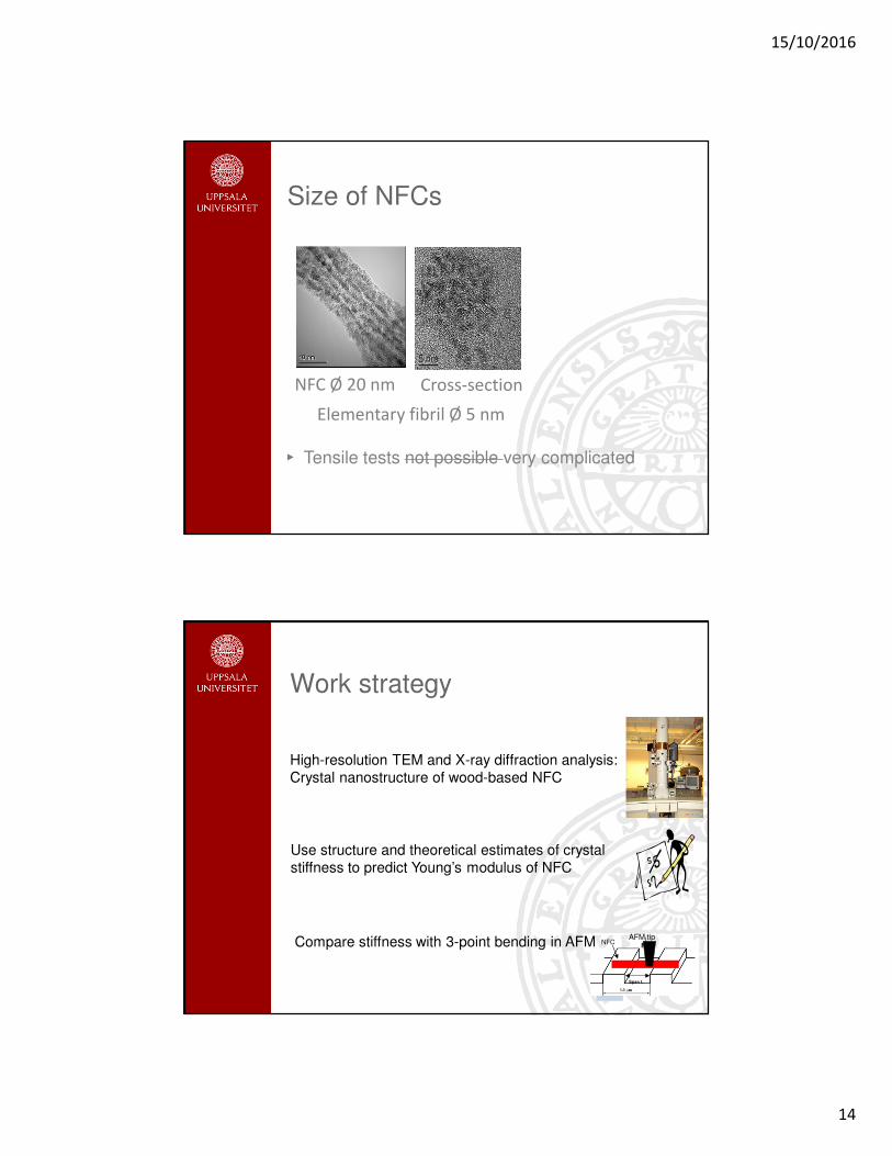
Size of NFCs
Cross-section
5 nm5 nm
NFC Ø 20 nm
Elementary fibril Ø 5 nm
Tensile tests not possible very complicated
Work strategy
High-resolution TEM and X-ray diffraction analysis: Crystal nanostructure of wood-based NFC
Use structure and theoretical estimates of crystal stiffness to predict Young’s modulus of NFC
Compare stiffness with 3-point bending in AFM FNFC
Span L
AFM tip

15/10/2016
15
Wood NFC from homogenized Norway spruce sulphite pulp (Borregaard)
S
Cellulose microfibril
Fibril
Hemicellulose
Lignin
Wood pulp fibre
S
S
P
3
2
1
Ø 20-30 nm
Ø 3-5 nm
NFC dimensions
15/10/2016
16
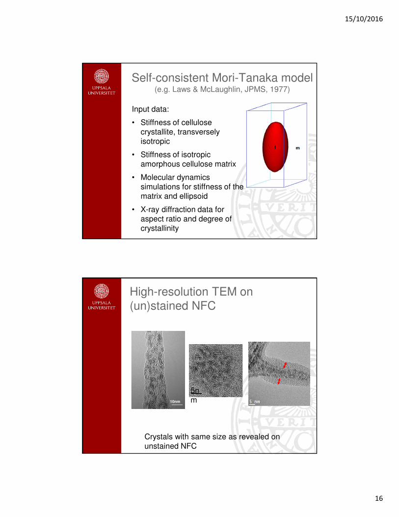
Self-consistent Mori-Tanaka model(e.g. Laws & McLaughlin, JPMS, 1977)
Input data:
• Stiffness of cellulosecrystallite, transverselyisotropic
• Stiffness of isotropicamorphous cellulose matrix
• Molecular dynamicssimulations for stiffness of the matrix and ellipsoid
• X-ray diffraction data for aspect ratio and degree ofcrystallinity
High-resolution TEM on (un)stained NFC
Crystals with same size as revealed on unstained NFC
5nm10nm

15/10/2016
17
X-ray diffraction results
10 15 20 25 30 35 40
2θ (degree)
Inte
ns
ity
Estimates based on Scherrer equation
Crystal width: D =0.9λ/Bcos(θ) at (200)
Crystal length: D =0.9λ/Bcos(θ) at (004)
Crystallinity: (I200 – IAm)/I200
Iβ(200)
Iβ(004)
An aspect ratio of 1.9 is obtained
A crystallinity of 69% is obtained
Crystals oriented along fibril direction
Crystallite aspect ratio
X-ray diffraction data from wood cell wall typically give an aspect ratio of ~ 5-8
M. Peura et. al. Trees 2008, 22, 49-61 (Norway spruce)
M. Peura et. al, Wood Sci Tecnol 2007, 41, 565-583 (Norway spruce)
Chemical/enzymatic pretreatment and homogenization reduce the crystal aspect ratio in MFC?
15/10/2016
18
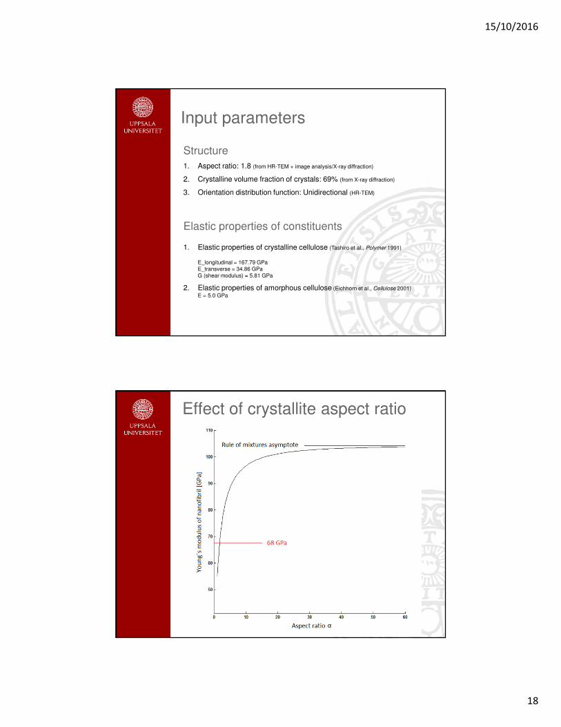
Structure
1. Aspect ratio: 1.8 (from HR-TEM + image analysis/X-ray diffraction)
2. Crystalline volume fraction of crystals: 69% (from X-ray diffraction)
3. Orientation distribution function: Unidirectional (HR-TEM)
Elastic properties of constituents
1. Elastic properties of crystalline cellulose (Tashiro et al., Polymer 1991)
E_longitudinal = 167.79 GPaE_transverse = 34.86 GPaG (shear modulus) = 5.81 GPa
2. Elastic properties of amorphous cellulose (Eichhorn et al., Cellulose 2001)
E = 5.0 GPa
Input parameters
Effect of crystallite aspect ratio
15/10/2016
19
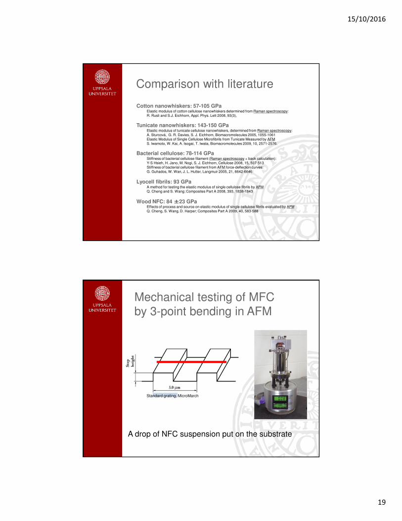
Comparison with literature
Cotton nanowhiskers: 57-105 GPaElastic modulus of cotton cellulose nanowhiskers determined from Raman spectroscopy: R. Rusli and S.J. Eichhorn, Appl. Phys. Lett 2008, 93(3),
Tunicate nanowhiskers: 143-150 GPaElastic modulus of tunicate cellulose nanowhiskers, determined from Raman spectroscopy: A. Sturcová, G. R. Davies, S. J. Eichhorn, Biomacromolecules 2005, 1055-1061Elastic Modulus of Single Cellulose Microfibrils from Tunicate Measured by AFMS. Iwamoto, W. Kai, A. Isogai, T. Iwata, Biomacromolecules 2009, 10, 2571-2576.
Bacterial cellulose: 78-114 GPaStiffness of bacterial cellulose filament (Raman spectroscopy + back calculation): Y-S Hsieh, H. Jano, M. Nogi, S. J. Eichhorn, Cellulose 2008, 15, 507-513Stiffness of bacterial cellulose filament from AFM force-deflection curves: G. Guhados, W. Wan, J. L. Hutter, Langmuir 2005, 21, 6642-6646
Lyocell fibrils: 93 GPaA method for testing the elastic modulus of single cellulose fibrils by AFM Q. Cheng and S. Wang; Composites Part A 2008, 393, 1838-1843
Wood NFC: 84 ±±±±23 GPaEffects of process and source on elastic modulus of single cellulose fibrils evaluated by AFMQ. Cheng, S. Wang, D. Harper; Composites Part A 2009, 40, 583-588
Mechanical testing of MFC by 3-point bending in AFM
Standard grating, MicroMarch
A drop of NFC suspension put on the substrate

15/10/2016
20
FMFC
Span L
AFM tip
Beam load-deflection relation
FL3
192δIE =
πD4
64I =
100 nm100 nm
Shape of MFC cross-section
TEM cross section of macrofibrils TEM cross section of MFC
Moment of inertia: Solid cylinder
5 nm
15/10/2016
21
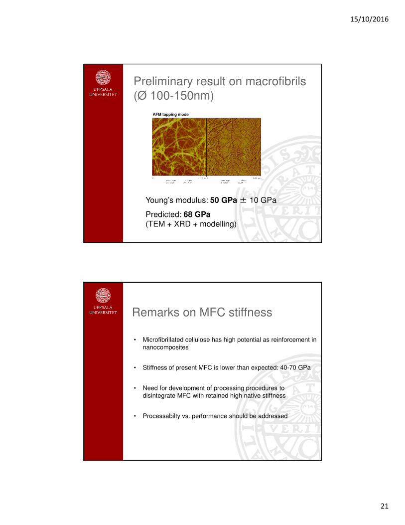
Preliminary result on macrofibrils (Ø 100-150nm)
Young’s modulus: 50 GPa± 10 GPa
Predicted: 68 GPa(TEM + XRD + modelling)
AFM tapping mode
Remarks on MFC stiffness
• Microfibrillated cellulose has high potential as reinforcement in nanocomposites
• Stiffness of present MFC is lower than expected: 40-70 GPa
• Need for development of processing procedures to disintegrate MFC with retained high native stiffness
• Processabilty vs. performance should be addressed
15/10/2016
22
Moisture-induced dimensionally instability
Contribution from cellulose microfibrils
Moisture uptake in wood-
based materials
polysaccharides
Dimensional instability, degradation of properties, fungal attack etc.
15/10/2016
23
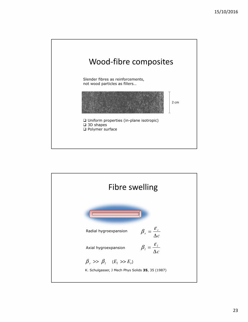
Wood-fibre composites
Slender fibres as reinforcements, not wood particles as fillers…
Uniform properties (in-plane isotropic) 3D shapes Polymer surface
2 cm
Fibre swelling
c
rr
∆=
εβRadial hygroexpansion
c
ll
∆=
εβAxial hygroexpansion
lr ββ >> (El >> Er)
K. Schulgasser, J Mech Phys Solids 35, 35 (1987)
15/10/2016
24
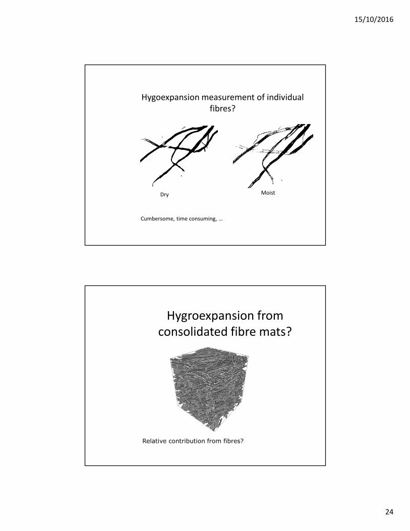
Hygoexpansion measurement of individual
fibres?
Dry Moist
Cumbersome, time consuming, …
Hygroexpansion from
consolidated fibre mats?
Relative contribution from fibres?
15/10/2016
25
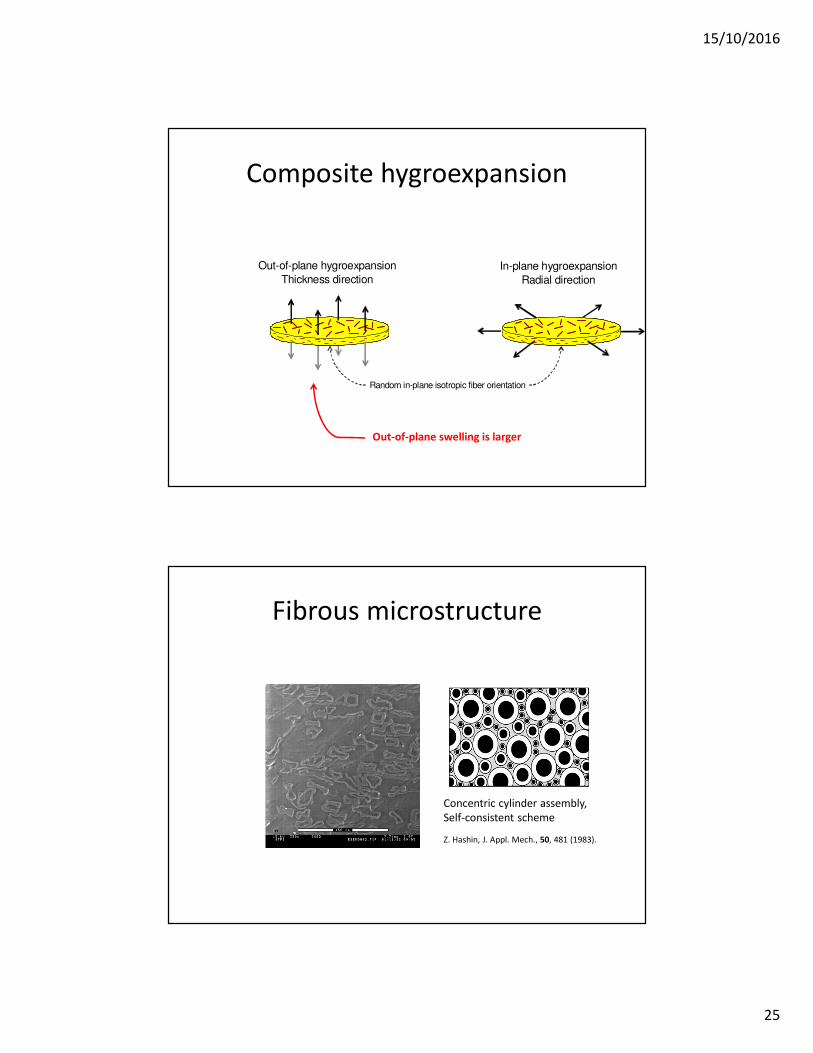
Composite hygroexpansion
Out-of-plane hygroexpansion
Thickness directionIn-plane hygroexpansion
Radial direction
Random in-plane isotropic fiber orientation
Out-of-plane swelling is larger
Fibrous microstructure
Concentric cylinder assembly,
Self-consistent scheme
Z. Hashin, J. Appl. Mech., 50, 481 (1983).

15/10/2016
26
Laminate analogy
Laminate theory
)42(8
1
)46(8
1
)4233(8
1
66122211
LAM
66
66122211
LAM
12
66122211
LAM
22
LAM
11
QQQQQ
QQQQQ
QQQQQQ
+−+=
−++=
+++==
TLTTL
TLTLTTTLLAM
2
)(
EEE
EEEL
rν
ββνβββ
++
+++=
In-plane stiffness
In-plane hygroexpansion

15/10/2016
27
Swelling constraint
L
T
z
In-plane isotropic substrate
Thin unidirectional ply
r
Calculated out-of-plane
hygroexpansion
TLTTL
LTTL
L
LT
T
T'T
LAM
2
)(
EEE
EE
EEz
ν
ββννββ
++
−
−+=
Experimentally measured
Depends on E and β of consituents
( )∑=
−N
i
iziz
1
2
fT
LAMLAM
,
fT
),(min
ββββ
x
Back out fibre hygroexpansion:

15/10/2016
28
Materials
Fibres
• Bleached kraft softwood fibres, Imatra Mill, Finland
Untreated - reference
• Same fibres
Cross-linked BTCA (butyltetracarboxylic acid)
Matrix
• Polylactic acid
Composite
• 30 and 40 v% fibres
• Hot-press moulding
Fibres of polylactic acid
Hot-pressing of commingled fibre mats
Maintained fibre slenderness
Wood fibresConsolidated solid composite
HeatPressure
15/10/2016
29
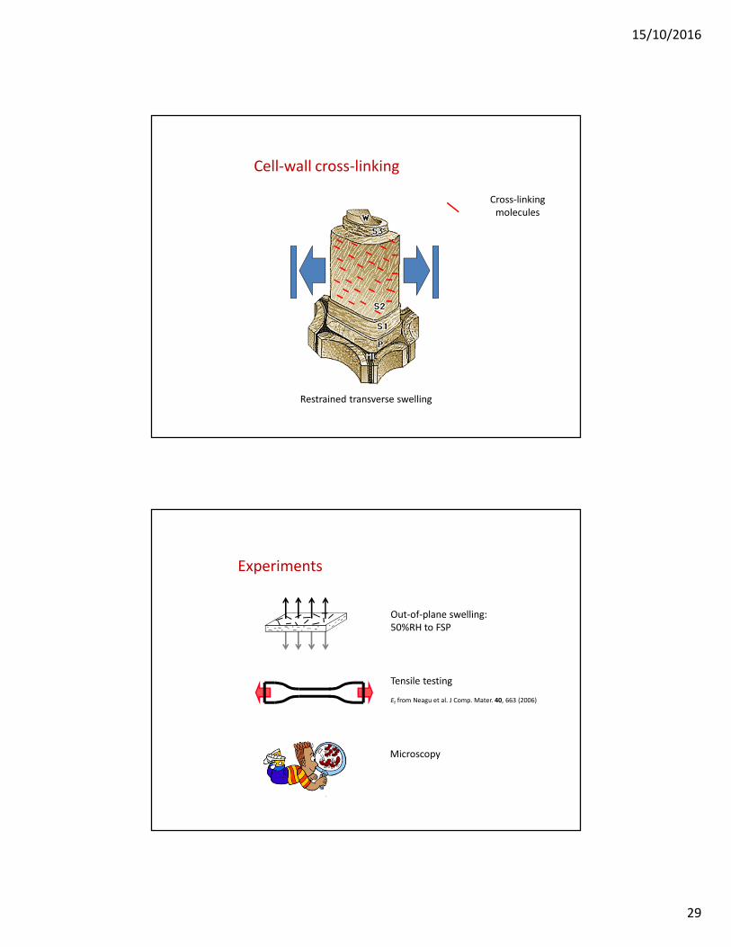
Cell-wall cross-linking
Cross-linking
molecules
Restrained transverse swelling
Experiments
Out-of-plane swelling:
50%RH to FSP
Tensile testing
Ef from Neagu et al. J Comp. Mater. 40, 663 (2006)
Microscopy

15/10/2016
30
Input parameters
Em
(GPa)νm
βm
(ε/RH)
EfL BTCA
(GPa)νfL ref, νfT ref
EfL ref
(GPa)νfL BTCA, νfT BTCA
3.6 0. 35 10-4 34.4 0.3 37.7 0.3
Constituent properties (measured or assumed)
Composite swelling (Vf = 0.40)
Reference 8.5 %
Cross-linked 4.8 %
Back calculation
δ
RH
ββββfibre = ?

15/10/2016
31
Results
Type β (ε/RH)
Reference 0.17
Cross-linked 0.10
Estimated from paper properties 0.22I. Kajanto & K. Niskanen. Paper Physics, Fapet(1998)
Determined by FEM simulations 0.12-0.13K. Persson, PhD thesis LTH (2000)
Estimated from wood samples 0.21 L. Wallström et al. Holz Roh Werkst. 53, 87 (1995)
Effect of anisotropy ratio
0
0.02
0.04
0.06
0.08
0.1
0.12
0.14
0.16
0.18
0.2
1 3 5 7 9
Anisotropy ratio E L/E T
Tra
ns
ve
rse
co
eff
icie
nt
of
hy
gro
ex
pa
ns
ion
Reference
BTCA
L
T
T
L
β
β=
E
Emust be assumed
15/10/2016
32
Concluding remarks
• Sensitivity to moisture
• Inverse modelling to identify transverse fibre hygroexpansion
coefficient
• Cell-wall cross-linking reduce hygroexpansion coefficient
significantly
• Simple method that could be used in ranking fibre modification
• Almgren et al. Polym. Compos. 31, 762 (2010), Joffre et al.
(2014, 2015)
Characterization of nanoscale fracture processes
Fengzhen Sun (PhD student)Kristofer Gamstedt
Collaboration wtih Hu Li (graduate student), Klaus Leifer (professor)
Applied Materials Science, Uppsala University
Henrik Lindberg (professor emeritus)Luleå University of Technology 64
15/10/2016
33
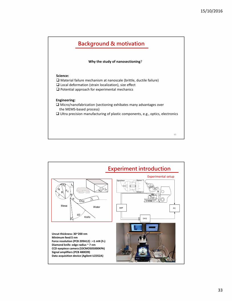
Background & motivation
Why the study of nanosectioning?
65
Science:
Material failure mechanism at nanoscale (brittle, ductile failure)
Local deformation (strain localization), size effect
Potential approach for experimental mechanics
Engineering:
Micro/nanofabrication (sectioning exhibates many advantages over
the MEMS-based process)
Ultra precision manufacturing of plastic components, e.g., optics, electronics
Uncut thickness: 30~200 nm
Minimum feed:5 nm
Force resolution (PCB 209A12) : <1 mN (Fc)
Diamond knife: edge radius ~ 7 nm
CCD eyepiece camera (S3CMOS05000KPA)
Signal amplifiers (PCB 480E09)
Data acquisition device (Agilent U2352A)
Experiment introductionExperimental setup
66
15/10/2016
34
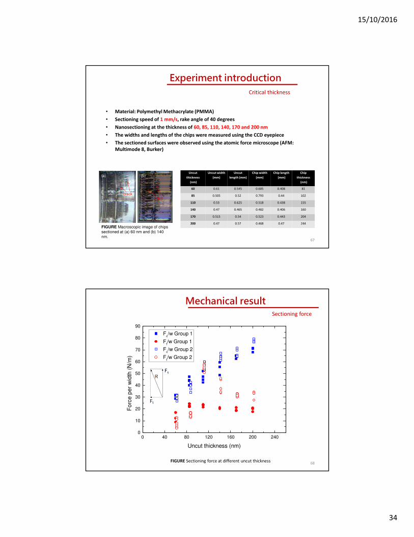
• Material: Polymethyl Methacrylate (PMMA)
• Sectioning speed of 1 mm/s, rake angle of 40 degrees
• Nanosectioning at the thickness of 60, 85, 110, 140, 170 and 200 nm
• The widths and lengths of the chips were measured using the CCD eyepiece
• The sectioned surfaces were observed using the atomic force microscope (AFM:
Multimode 8, Burker)
Experiment introductionCritical thickness
Uncut
thickness
(nm)
Uncut width
(mm)
Uncut
length (mm)
Chip width
(mm)
Chip length
(mm)
Chip
thickness
(nm)
60 0.61 0.545 0.605 0.408 81
85 0.505 0.52 0.793 0.44 102
110 0.53 0.625 0.518 0.438 155
140 0.47 0.465 0.482 0.406 160
170 0.515 0.54 0.523 0.443 204
200 0.47 0.57 0.468 0.47 244
67
(b)
crackcrack
FIGURE Macroscopic image of chips sectioned at (a) 60 nm and (b) 140 nm.
(a)
0 40 80 120 160 200 2400
10
20
30
40
50
60
70
80
90
Fc/w Group 1
Ft/w Group 1
Fc/w Group 2
Ft/w Group 2
Fo
rce
pe
r w
idth
(N
/m)
Uncut thickness (nm)
Mechanical resultSectioning force
FIGURE Sectioning force at different uncut thickness68
15/10/2016
35
[ ] 32144444 344444 21
4434421fracture
friction
c
ndeformatioplastic
yc RwVV
FwVtVF +−
⋅−+⋅=)cos(
sinsin)sec()()( 0
αφ
φβαβγτ
[ ]
−
−+
−−⋅+−+−=
−
−⋅
−−−
)(cos
)sin(sin
)cos(
cos
)cos(
sin)tan(cot
sin
1
)(cos
1
)cos()cos(
sinsin1
2
22
αφ
αφφ
αφ
φ
αβ
βαφφ
φαφαφαβ
φβ
Z
Q
Rwt
Q
wF
y
c +
= 0
γτ
[ ])cos()cos(/sinsin1correctionfriction αφαβφβ −−−=Q
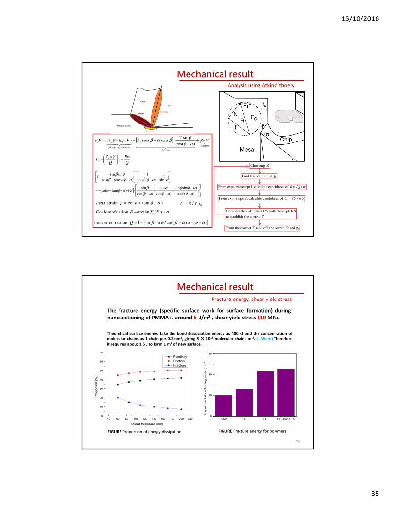
Mechanical resultAnalysis using Atkins’ thoery
)tan(cotstrainshear αφφγ −+=
αβ += )arctan(frictionCoulomb ct FF
Q, optimum theFind φ
wIQR / of candidates calculate I, intercerpt expt. From =
γτ wSQ / of candidates calculate S, slope expt. From y =
correct Z theestablish to
S/I expt. with theS/I calculated theCompare
y and Rcorrect theoff read correct Z, theFrom τ
ZChoosing
0/ tRZ yτ=
69
The fracture energy (specific surface work for surface formation) during
nanosectioning of PMMA is around 6 J/m2 , shear yield stress 110 MPa.
Theoretical surface energy: take the bond dissociation energy as 400 kJ and the concentration of
molecular chains as 1 chain per 0.2 nm2, giving 5×××× 1018 molecular chains m-2. (I. Ward) Therefore
it requires about 1.5 J to form 1 m2 of new surface.
40 60 80 100 120 140 160 180 200 2200
10
20
30
40
50
60
70
Pro
port
ion
(%
)
Uncut thickness (nm)
Plasticity
Friction
Fracture
PMMA PS PC DGEBA/DETA0
10
20
30
Exp
eri
me
nta
l se
ctio
nin
g w
ork
, (J
/m2)
Mechanical resultFracture energy, shear yield stress
FIGURE Fracture energy for polymersFIGURE Proportion of energy dissipation
70
15/10/2016
36
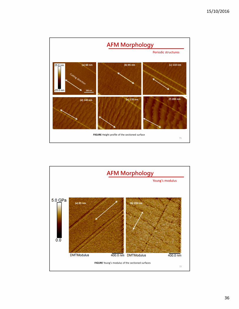
500 nm
(a) 60 nm (b) 85 nm (c) 110 nm
(d) 140 nm (e) 170 nm (f) 200 nm
AFM MorphologyPeriodic structures
FIGURE Height profile of the sectioned surface
71
(a) 85 nm (b) 200 nm
FIGURE Young’s modulus of the sectioned surfaces
AFM MorphologyYoung’s modulus
72

15/10/2016
37
• 60 nm: the sectioned surface is flat and smooth
• 85 nm: short and feeble wave-like features appears
• 110 nm: long and periodic wave-like structures (perpendicular to the
sectioning direction, bandwidth: 54 nm)
• 140, 170 and 200 nm: the periodicity becomes more pronounced
Uncut thickness (nm) Chip thickness (nm) Average spacing (nm)
60 81 --
85 102 --
110 155 150
140 160 215
170 204 209
200 244 383
AFM Morphology
Table 1 Average spacing between two adjecent structures
Periodicity of band
73
J. Black. On microscopic plastic instabilities in metal
machining chips, Metallurgical Transactions,1972
M Jiang, L Dai. Formation mechanism of lamellar chips
during machining of bulk metallic glass, Acta
Materialia, 2009
AFM MorphologyFormation of shear band
74

15/10/2016
38
AFM Morphology
(a) (b)
(c) (d)
Formation of periodic structures
FIGURE Schematic of the formation of periodic structures
sV
sV
FIGURE Schematic of the periodic structures
The influence of sectioning speed
76

15/10/2016
39
77
• Material: Polymethyl Methacrylate (PMMA)
• Sectioning depth of 85 nm, rake angle of 40 degrees
• Nanosectioning at the speed of 0.25, 0.5, 1.0 ,3.0, 10.0 mm/s
• Measurement of the widths and lengths of the chips by CCD eyepiece
• Morphology of the sectioned surfaces by atomic force microscope (AFM:
Multimode 8, Burker)
Experiment introductionCritical speed
0.5 mm/s0.25 mm/s
1.0 mm/s 3.0 mm/s 10 mm/s
AFM Morphology
15/10/2016
40
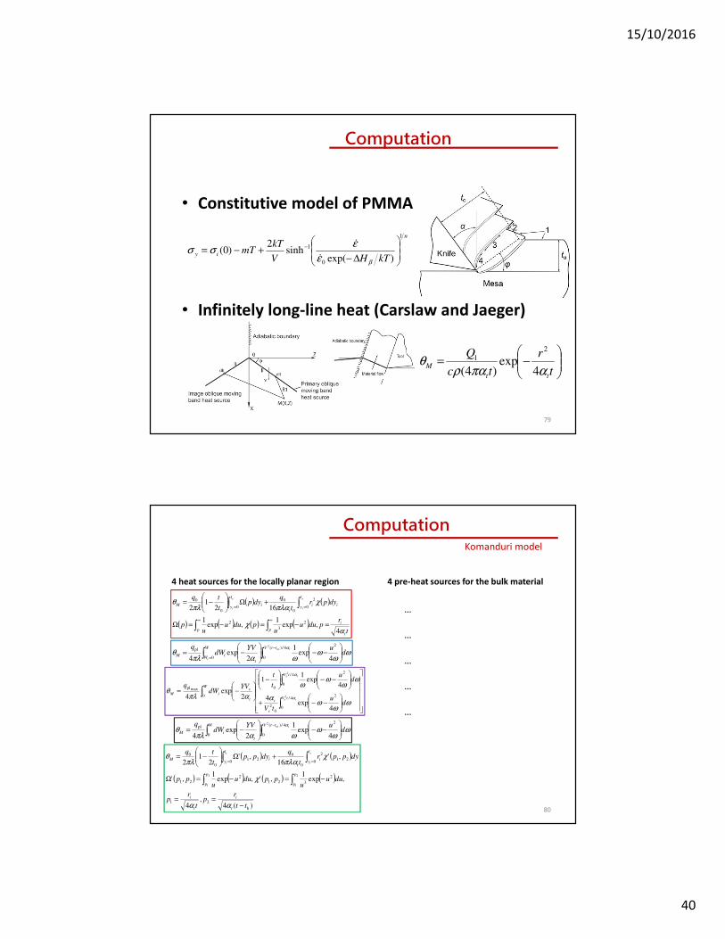
Computation
• Constitutive model of PMMA
• Infinitely long-line heat (Carslaw and Jaeger)
79
n
iykTHV
kTmT
1
0
1
)exp(sinh
2)0(
∆−+−= −
βε
εσσ
&
&
−=
t
r
tc
Q
tt
Mαπαρ
θ4
exp)4(
2
1
4 heat sources for the locally planar region
80
( ) ( )
( ) ( ) ( ) ( )t
rpduu
upduu
up
dyprt
qdyp
t
tq
t
i
pp
l
yii
t
l
yiM
s
i
s
i
αχ
χπλαπλ
θ
4,exp
1,exp
1
1621
2
2
3
2
0
2
0
0
00
0
=−=−=Ω
+Ω
−=
∫∫
∫∫∞∞
==
ωω
ωωαπλ
θα
duYV
dWq toi
i
ttVW
Wt
iM
−−
−= ∫∫
−
= 4exp
1
2exp
4
24/)(
00
pl2
−−+
−−
−
−=
∫
∫∫
ts
ts
tV
s
t
tV
W
t
siM
du
tV
du
t
t
YVdW
q
α
α
ωω
ωα
ωω
ωω
απλθ
4/
0
2
0
2
24/
00
0
maxpl
2
2
4exp
4
4exp
11
2exp
4
ωω
ωωαπλ
θα
duYV
dWq toittVW
t
iM
−−
−= ∫∫
−
4exp
1
2exp
4
24/)(
00
pl2
( ) ( )
( ) ( ) ( ) ( )
)(4,
4
,exp1
,',exp1
,'
,'16
,'2
12
h
21
2
321
2
21
021
2
0
0
021
0
0
2
1
2
1
tt
rp
t
rp
duuu
ppduuu
pp
dypprt
qdypp
t
tq
t
i
t
i
p
p
p
p
l
yi
t
l
yiM
s
i
s
i
−==
−=−=Ω
+Ω
−=
∫∫
∫∫ ==
αα
χ
χπλαπλ
θ
4 pre-heat sources for the bulk material
ComputationKomanduri model
…
…
…
…
…
15/10/2016
41
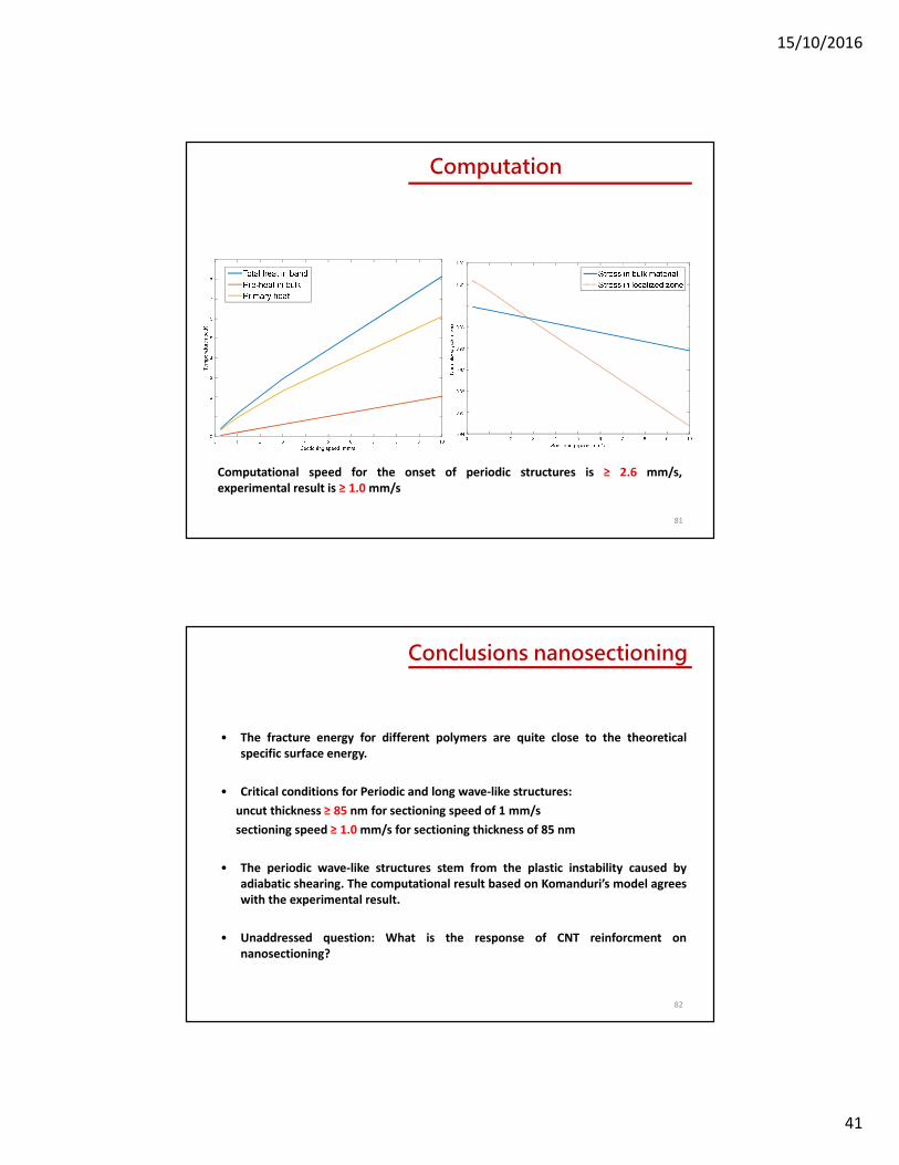
81
Computation
Computational speed for the onset of periodic structures is ≥ 2.6 mm/s,
experimental result is ≥ 1.0 mm/s
Conclusions nanosectioning
• The fracture energy for different polymers are quite close to the theoretical
specific surface energy.
• Critical conditions for Periodic and long wave-like structures:
uncut thickness ≥ 85 nm for sectioning speed of 1 mm/s
sectioning speed ≥ 1.0 mm/s for sectioning thickness of 85 nm
• The periodic wave-like structures stem from the plastic instability caused by
adiabatic shearing. The computational result based on Komanduri’s model agrees
with the experimental result.
• Unaddressed question: What is the response of CNT reinforcment on
nanosectioning?
82

15/10/2016
42
Thank you for your attention!
83