KOWA INSTRUCTION MANUAL Congratulations on your purchase of the KOWA SL-17. This manual provides a...
32
INSTRUCTION MANUAL PORTABLE SLIT-LAMP KOWA EU KOWA SL-17
-
Upload
phamnguyet -
Category
Documents
-
view
213 -
download
1
Transcript of KOWA INSTRUCTION MANUAL Congratulations on your purchase of the KOWA SL-17. This manual provides a...

INSTRUCTION MANUAL
PORTABLE SLIT-LAMP
KOWA
EUKOWA SL-17


I
Congratulations on your purchase of the KOWA SL-17. This manual provides a description of the operating procedures and important precautions to be observed during its use. Please read this manual carefully to ensure
manual in an easily accessible location for future reference.
This manual describes important precautions to be observed when you use the instrument to ensure that the instrument is used safely without causing any damage to the human body or property of the purchaser and other persons.The following designations and pictorial symbols should be fully comprehended before reading the manual.
Meanings of designations
Warning Improper operation may result in serious injury*1 or death.
Caution Improper operation may result in bodily injury*2 or property damage*3.
causes a subsequent complication or requires hospitalization or long-term outpatient treatment.
outpatient treatment.*3 Damage to property means extensive damage to a house and/or household goods as well as a domestic animal and pet.
Meanings of symbols
Graphical indication of any warning and caution.What is warned is explicitly and pictorially indicated by a picture or its associated mes-sage on or near a pictorial symbol.
Graphical indication of prohibited operation (prohibitive item).What is prohibited is explicitly and pictorially indicated by a picture or its associated mes-sage on or near a pictorial symbol.
Graphical indication of any mandatory action (obligatory item).What must always be done is explicitly and pictorially indicated by a picture or its associ-ated message on or near a pictorial symbol.
Disclaimer
Kowa is not responsible for:
loss of stored data and so forth).
Introduction
II
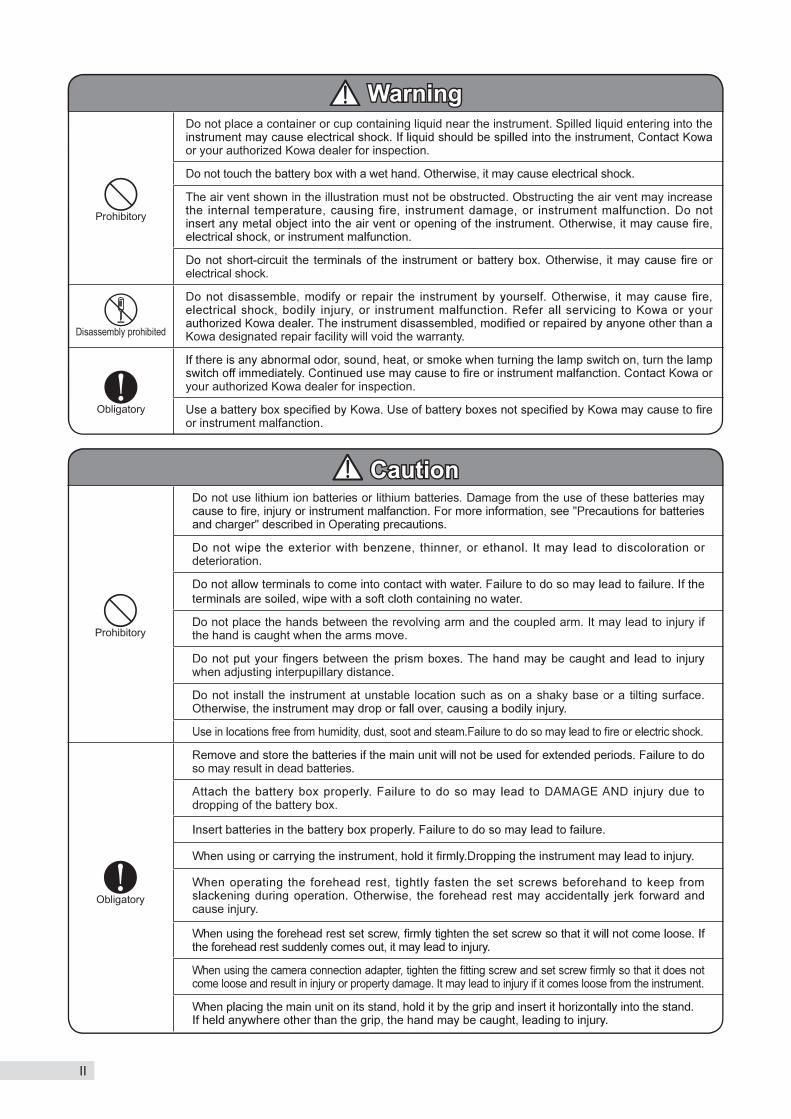
Warning
Prohibitory
Do not place a container or cup containing liquid near the instrument. Spilled liquid entering into the
or your authorized Kowa dealer for inspection.
The air vent shown in the illustration must not be obstructed. Obstructing the air vent may increase
electrical shock.
Disassembly prohibited Kowa designated repair facility will void the warranty.
Obligatory
your authorized Kowa dealer for inspection.
or instrument malfanction.
Caution
Prohibitory
Do not use lithium ion batteries or lithium batteries. Damage from the use of these batteries may
deterioration.
Do not place the hands between the revolving arm and the coupled arm. It may lead to injury if the hand is caught when the arms move.
when adjusting interpupillary distance.
Do not install the instrument at unstable location such as on a shaky base or a tilting surface.
Obligatory
so may result in dead batteries.
dropping of the battery box.
cause injury.
come loose and result in injury or property damage. It may lead to injury if it comes loose from the instrument.

III
Meanings of symbols
Symbol for “Follow instruction manual for use”
Symbol for “Type B applied part”
Symbol for “Authorised Repre-sentative in the European Com-munity”
Symbol for “Manufacturer”

IV
1. Operating environment
instrument. Strictly observe the following environmental conditions.Operational Transport and storage
Environmental temperature 10 to 35 15 to 55 Relative humidity 30 to 90 % 10 to 95 %
Atmospheric pressure 800 to 1 060 hPa
2. Precautions for electrical systems
2) Kowa is not liable for malfunction and/or damages resulting from maintenance and/or repairs performed by a third party other than an agent authorized by Kowa.
3) Kowa is not liable for malfunction and/or damages resulting from maintenance and/or repairs using parts other
3. Precautions when using this instrument 1) Disinfect all parts accessible by the patient with alcohol. 2) Handle the instrument carefully and do not subject it to strong impact. Do not operate the instrument after it has
3) Disinfect using alcohol the parts accessible by the patient. Severe damage or deterioration of the exterior Deterioration or leaking of batteries
5) Always cover this instrument with dust cover when not in use in order to protect.
4. Disposal precautions
disposal is handled by a licensed industrial waste disposal contractor in accordance with the applicable regulations and ordinances.
Precautions for batteries and charger
Make sure that batteries are inserted in the instrument in correct polarity positions. Batteries inserted in the wrong direction may lead to failure.
Prohibitory Do not use lithium ion batteries or lithium batteries. Damage from the use of these batteries
Read respective instruction manuals for precautions on batteries and chargers.
Obligatory
for extended periods (three months or longer). Leaving the batteries inside the instrument for
contact the respective battery or charger manufacturers.
Operating precautions

V
Precautions: use of medical electrical system
1. Precautions for use of medical electrical systemThis instrument constitutes medical electric system by connecting with the following optional accessories.
In order to take or save the picture with camera connection adapter of SL-17.
Recommended camera can be installed in patient environment (within a radius of 1.5m around a patient).
secure system according to notes currently written here.
2. Precautions for use of medical electrical system 1) Any medical electrical equipment that is connected to this system to compose a medical system must
comply with IEC 60601-1. 2) Any non-medical electrical equipment that is connected to this system to compose a medical system must
comply with safety standards of IEC or ISO provisions applicable to such non-medical electrical equipment. 3) The system which consists of this instrument and other electrical devices (here in after referred to as
“this system”) must comply with IEC 60601-1 when may be installed and used all within a limited patient environment
4) This system must comply with safety standards of IEC or ISO provisions when may be installed and used outside patient environment.
7) Do not place or install the devices and the system components on the unstable or inclined table.
3. Daily maintenance and cleaning System components
excessive soils. Do not use chemicals or solvents such as thinner or benzene. (As the monitor screen

VI
Operational considerations for a hospital grade electrical instrument (safety and accident prevention)
2. The following items shall be considered when installing the instrument. 1) Install at a location away from water or accidental splashing.
4) Instrument must not be installed at locations where chemicals are stored or gasses are generated.
3. The following items shall be considered before using the instrument.
2) Use of other instruments and appliances on the same power outlet is liable to cause errors and incorrect output resulting in incorrect diagnosis or hazards.
4. The following items shall be considered when using the instrument. 1) Make sure to minimize the time required for diagnosis. 2) Always assure that the instrument and patient are in good condition.
of the instrument while assuring the patient’s safety. 4) Do not allow the patient to touch any part of the instrument except for the forehead rest.
5. The following items shall be considered after using the instrument. 1) The following shall be considered regarding storage location.
( ) Store at a location away from water or accidental splashing.( -
(( ) Instrument must not be stored at locations where chemicals are stored or gasses are generated.
3) The instrument must be cleaned after using so that there will be no problem when using it again.
6. In case of a problem or malfunction, do not attempt to repair the instrument by yourself. Appropriately
8. Maintenance 1) Periodically check the instrument and its components for any abnormality.
that it is in normal condition and operates safely.
9. Be careful of the possibility that incorrect operation may be caused by strong electromagnetic waves.This instrument is examined based on IEC 60601-1-2.The purpose of this standard is to keep safety against the dangerous obstacle in typical medical facilities.
relocate this instrument and other apparatus or extend the distance between those instruments.
VII
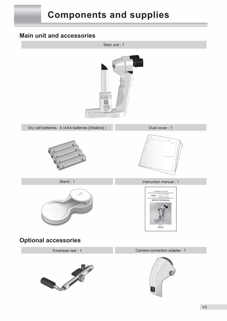
Components and supplies
Main unit and accessoriesMain unit : 1
Dust cover : 1
Stand : 1 Instruction manual : 1
Optional accessoriesCamera connection adapter : 1

VIII
Contents

memo
1
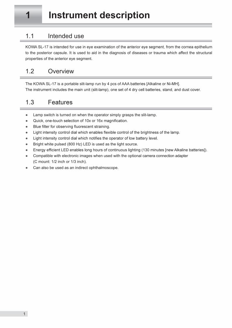
1.1 Intended use
to the posterior capsule. It is used to aid in the diagnosis of diseases or trauma which affect the structural properties of the anterior eye segment.
1.2 Overview
The KOWA SL-17 is a portable slit-lamp run by 4 pcs of .
Lamp switch is turned on when the operator simply grasps the slit-lamp.
Bright white pulsed (800 Hz) LED is used as the light source.
Compatible with electronic images when used with the optional camera connection adapter (C mount: 1/2 inch or 1/3 inch).
Can also be used as an indirect ophthalmoscope.
1 Instrument description

2
1 Instrument description
1Main unit (slit-lamp)
Bottom view
Light intensity control dialTurn the light intensity control dial to the right or left; the light become b r igh te r o r darke r respectively
replace batteries by blinks when battery level becomes low.
Upper cover
Lamp switch
lever with grip in hand. Release the lever to turn it off.
Magnifying power select leverTurn the lever in the directions of to select a magnifying power of 10 or 16.
Coupled arm
Grip
Battery box
Revolving arm
Objective lensAn image 10 t imes as large as a subject can be observed. An image 16 times as large as a subject can be observed by advancing the lens.
Eyecup
Slit-disk
Spot-diskSelect the spot diameter or use of the blue filter. Select a spot diameter of
12mm.
Air vent
Arm swing
angle scale
Point to the swing angle sca le of illumination light.
Projection lens
EyepieceDiopter adjustment ring
Adjusts the diopter.
Prism box
part both ways.
Red dot

3
2 Preparation
2.1 Inserting batteries in the main unit
Remove the battery box from the main unit.
out to open it.
battery box. The method of inserting batteries is to insert from the terminal and push on the terminal.
Return the battery box to the main unit. Insert the battery box until the tab makes a click sound.
damage or injury.
Push the lamp switch to see if the lamp and the light intensity control dial light.
2.2 Adjusting interpupillary distance and diopter
Adjusting interpupillary distance
interpupillary distance width by rotating both prism boxes in opposite directions.
Adjusting diopter With the diopter adjustment ring turned to its full plus (
into the eyepiece with each eye while slowly turning it to its minus ( )
A person wearing eyeglasses may use the eyepiece with the eyecup folded forward.

4
memo

5
3 How to use
3.1 How to operate the slit lamp
Use the grip to hold the main unit securely in your hand. Place the thumb of your other hand on the side of the upper cover of
Stabilize slit width indication by adjusting the distance between
* main unit.)Please push the lamp switch and irradiate the light for various observation of eye.
3.2 How to operate other functions
Turn the magnifying power select lever to the left as indicated by
arrow-head to select a magnifying power of 16. Turn it to the right to select a magnifying power of 10.
Changing slit-width
point marking a red dot. Changing the spot light size/inserting the blue filter spot light can
be switched among 12 mm by rotating the
is inserted. Depending on a combination of the slit-disk and the spot-
Light adjustment Turn the light intensity control dial to the right or left; the light
Turn to the left Turn to the right
Dark Bright 1 2 3 4 5

6
3 How to use
3
How
to use
3.3 How to use the stand
Hold the main unit by the grip and insert it horizontally into the stand.
Caution
Prohibitory
Do not install the main unit and stand at a unstable location such as on a shaky base or a
injury.
Obligatory
7
3 How to use
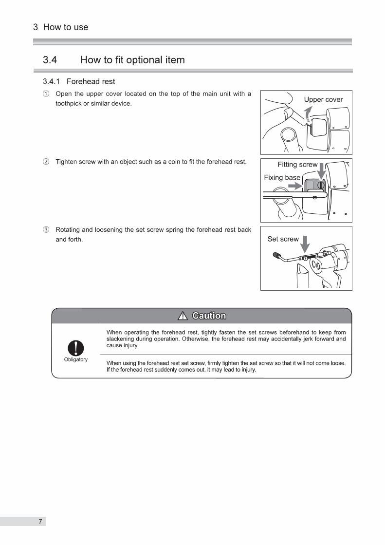
Open the upper cover located on the top of the main unit with a toothpick or similar device.
Rotating and loosening the set screw spring the forehead rest back and forth.
Caution
Obligatory
cause injury.

8
3 How to use
3
How
to use
3.4.2 Camera connection adapter Open the upper cover located on the top of the main unit with a
toothpick or similar device.
Loosen the locking screw attached to right and left both sides of the
not project. Tighten the locking screw the camera connection adapter with the
magnifying power of 16.
Caution
Obligatoryso that it does not come loose and result in injury or property damage. It may lead to injury if it comes loose from the instrument.

9
This instrument is a precision instrument and daily maintenance and inspection may affect the imaging results.Please read this section carefully in order to use this instrument correctly and safely.
4.1 Regular maintenance
Make sure to place the dust cover on the instrument after use.
Clean the terminal part of the main unit and the battery box and batteries with a soft piece of cloth
remove batteries from the battery box.
4.2 Daily inspection
Inspect this instrument in accordance with “KOWA SL-17 daily inspection table” below.
KOWA SL-17 daily inspection table
Inspection item Procedure Acceptability criteria
Main unit(slit-lamp)
Enclosure Visually verify that there is no problem. There is no deformation.
Projection lensObjective lensLens of eyepieces
Visually verify that there are no f laws or contaminants on the lenses.
Lamp switch Operate the switch to see i f i t works normally. light intensity control dial should
light.
Slit-diskSpot-disk
Move the disk to see that it moves without any problems and has clicks.
The disk should move smoothly. There should be clicks.
Magnifying power select lever
Move the lever to see that it moves without any problems. The lever should move smoothly.
Light intensity control dial
Move the dial to see that it moves without any problems. The dial should move smoothly.
Rating labelVisually check that the label is securely instal led and that al l indications are clearly visible.
The labe l must be securely installed.All indications must be clearly visible.
Terminal part Visually check if the terminal parts are soiled.
They should not be soiled or black.
Battery box
Enclosure Visually verify that there is no problem. There is no deformation.
Terminal part Visually check if the terminal parts are soiled.
They should not be soiled or black.
Stand Enclosure Visually verify that there is no problem. There is no deformation.
4 Maintenance and inspection
10
4 Maintenance and inspection
4
Maintenance and inspection
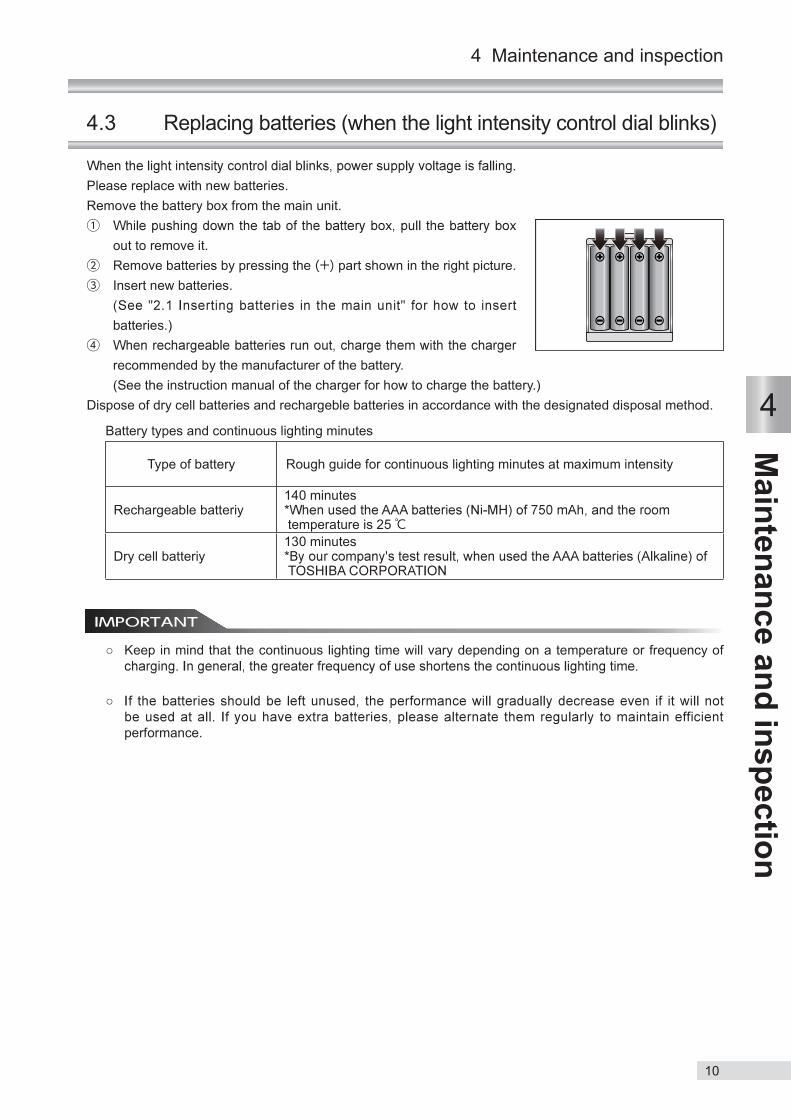
4.3 Replacing batteries (when the light intensity control dial blinks)
Please replace with new batteries.Remove the battery box from the main unit.
out to remove it. Remove batteries by pressing the part shown in the right picture. Insert new batteries.
batteries.)
recommended by the manufacturer of the battery. (See the instruction manual of the charger for how to charge the battery.)Dispose of dry cell batteries and rechargeble batteries in accordance with the designated disposal method.
Battery types and continuous lighting minutes
Type of battery Rough guide for continuous lighting minutes at maximum intensity
Rechargeable batteriy140 minutes
temperature is 25
Dry cell batteriy130 minutes
Keep in mind that the continuous lighting time will vary depending on a temperature or frequency of
performance.

11
4 Maintenance and inspection
4.4 Cleaning
4.4.1 Cleaning and disinfecting the forehead rest
Make sure to wipe the forehead rest with rubbing alcohol as soon as a patient completes the examination.
4.4.2 Cleaning the exterior
Caution
Prohibitory
deterioration.
clean it. Blow off debris or dust on the lens surfaces using a blower. When it cannot cleaned by step
with cleaning solution made from ethyl alcohol and ether (1:1) and lightly wipe whole surface of the lens starting from its center in a circular motion. Repeat this step several times.
If any soil is left after step .
If any soil cannot be removed by steps through dealer.
beforehand may scratch the lens surface.
and ether.
Do not use any other agent or cloth.

12
5
Troubleshooting 5 Troubleshooting
following list and apply the applicable remedy. If the described applicable remedy does not eliminate the problem
This section describes troubleshooting procedures to solve problems you may encounter.Abnormal performance of the instrument
Problem What to check State of instrument Applicable remedy
The lamp does not light when the lamp switch is pushd.
Is the battery box in place? Mount the battery box.
Is the light intensity control dial blinking?insert the rechargeable batteries which are not being charged enough.Replace new batteries.
Battery is coming out.positions.
Are the batteries being inserted in opposite of the positive and negative? positions written on the battery box.
Spot-disk is wrongly set at a point away from the red dot.
Set the spot-disk at the red dot.
Slit-disk is wrongly set at a point away from the red dot.
Set the slit-disk at the red dot.
Does the light intensity control dial rotate? dial to the right to increase light intensity.
The lamp goes off quickly. (battery consumption is fast)
Are the batteries charged?charge the batteries.
Are the batteries depleted?Replace with new batteries.Rechargeable batteries gradually deplete after repeating charge and discharge.
The slit tilts.Slit-disk is wrongly set at a point away from the red dot.
Set the slit-disk and spot-disk at the red dot.
Part of the illumination light or slit is obscured.
Slit-disk or spot-disk is wrongly set at a point away from the red dot.
Set the slit-disk at the red dot.
Out of focus.Diopter is wrongly set at a point away from a desired value.
Adjust to a desired diopter.
13
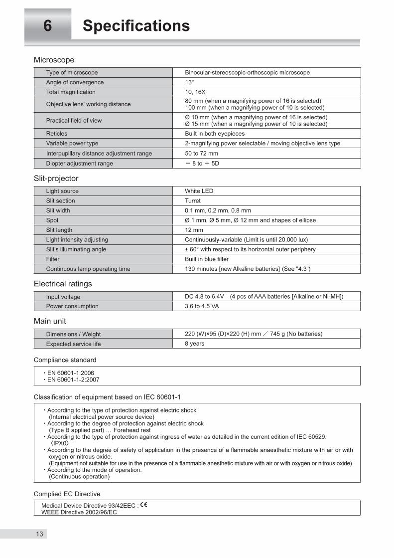
MicroscopeType of microscope Binocular-stereoscopic-orthoscopic microscopeAngle of convergence 13°
80 mm (when a magnifying power of 16 is selected)100 mm (when a magnifying power of 10 is selected)Ø 10 mm (when a magnifying power of 16 is selected)Ø 15 mm (when a magnifying power of 10 is selected)
Reticles Built in both eyepiecesVariable power type 2-magnifying power selectable / moving objective lens type
Interpupillary distance adjustment range 50 to 72 mm
Diopter adjustment range 8 to 5D
Slit-projectorLight source White LEDSlit section TurretSlit widthSpot Ø Ø Ø 12 mm and shapes of ellipseSlit length 12 mmLight intensity adjusting
± 60° with respect to its horizontal outer periphery
Continuous lamp operating time
Electrical ratingsInput voltage DC 4.8 to 6.4VPower consumption 3.6 to 4.5 VA
Main unitDimensions / Weight 220 (W)×95 (D)×220 (H) mm
Expected service life 8 years
Compliance standard
According to the type of protection against electric shock (Internal electrical power source device)
According to the degree of protection against electric shock
According to the type of protection against ingress of water as detailed in the current edition of IEC 60529.
oxygen or nitrous oxide.
According to the mode of operation. (Continuous operation)
Complied EC Directive
Medical Device Directive 93/42EEC : WEEE Directive 2002/96/EC
14
7
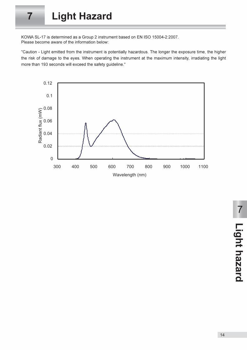
Light hazard 7 Light Hazard
Please become aware of the information below:

15
8 Electromagnetic compatibility
This instrument is a electrical medical instrument. Electrical medical instruments require special attention to the electromagnetic compatibility (EMC). The following section describes the EMC and precautions regarding
described.(The EMC of this instrument was tested based on IEC 60601-1-2.)
instrument) may adversely affect this instrument resulting in malfunctioning.
2. The electromagnetic compatibility (EMC) of this instrument was tested with the accessories shown below.
Camera connection adapter
3. This instrument is not designed to be used adjacent to a external instrument or placed on top of another.
constantly to ensure the instrument is functioning normally after such use has been adopted.
compatibility (EMC) of this instrument.
Basic operations
16
8 Electromagnetic compatibility
8
Electromagnetic com
patibility
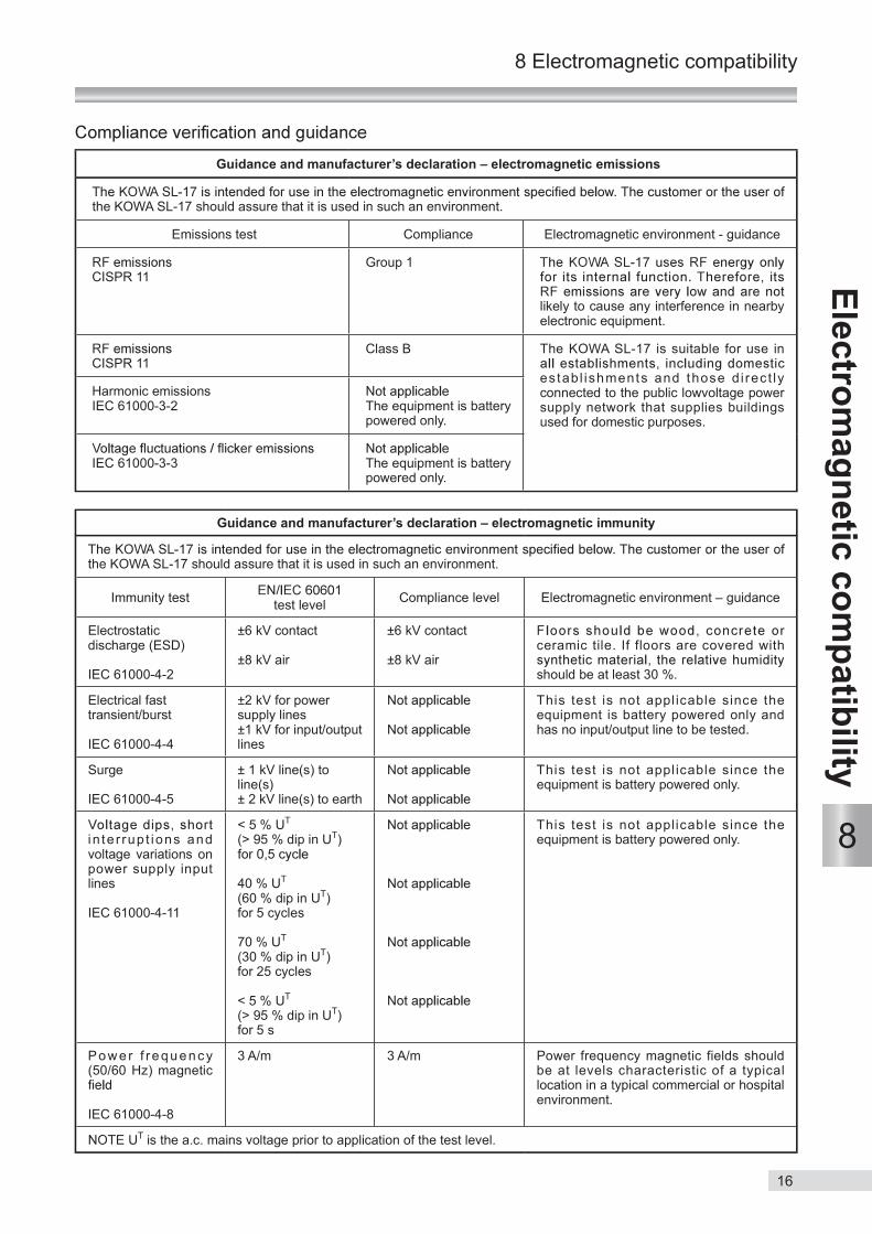
Guidance and manufacturer’s declaration – electromagnetic emissions
the KOWA SL-17 should assure that it is used in such an environment.
Emissions test Compliance Electromagnetic environment - guidance
CISPR 11Group 1
likely to cause any interference in nearby electronic equipment.
CISPR 11Class B The KOWA SL-17 is suitable for use in
estab l ishments and those d i rec t ly connected to the public lowvoltage power supply network that supplies buildings used for domestic purposes.
Harmonic emissionsIEC 61000-3-2 The equipment is battery
powered only.
IEC 61000-3-3 The equipment is battery powered only.
Guidance and manufacturer’s declaration – electromagnetic immunity
the KOWA SL-17 should assure that it is used in such an environment.
Immunity test test level Compliance level Electromagnetic environment – guidance
Electrostatic discharge (ESD)
IEC 61000-4-2
±6 kV contact
±8 kV air
±6 kV contact
±8 kV airceramic tile. If floors are covered with
should be at least 30 %.
Electrical fasttransient/burst
IEC 61000-4-4
±2 kV for power supply lines±1 kV for input/outputlines
This test is not appl icable since the equipment is battery powered only and has no input/output line to be tested.
Surge
IEC 61000-4-5
± 1 kV line(s) to line(s)± 2 kV line(s) to earth
This test is not appl icable since the equipment is battery powered only.
in te r rup t ions and voltage variations on power supply input lines
IEC 61000-4-11
< 5 % UT
(> 95 % dip in UT)
40 % UT
(60 % dip in UT)for 5 cycles
70 % UT
(30 % dip in UT)for 25 cycles
< 5 % UT
(> 95 % dip in UT)for 5 s
This test is not applicable since the equipment is battery powered only.
Pow er f r equenc y (50/60 Hz) magnetic
IEC 61000-4-8
3 A/m 3 A/m Power frequency magnetic fields should be at levels characteristic of a typical location in a typical commercial or hospital environment.
UT is the a.c. mains voltage prior to application of the test level.
17
8 Electromagnetic compatibility
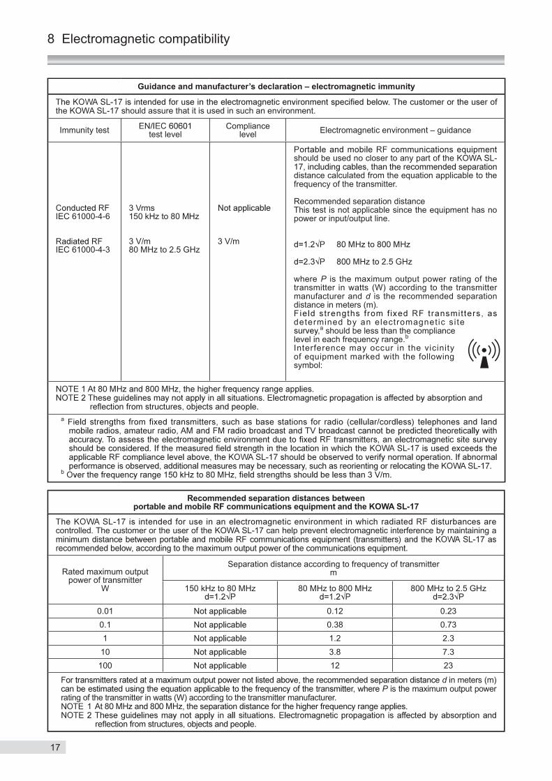
Guidance and manufacturer’s declaration – electromagnetic immunity
the KOWA SL-17 should assure that it is used in such an environment.
Immunity test test levelCompliance
level Electromagnetic environment – guidance
IEC 61000-4-6
IEC 61000-4-3
3 Vrms150 kHz to 80 MHz
3 V/m80 MHz to 2.5 GHz
3 V/m
should be used no closer to any part of the KOWA SL-
distance calculated from the equation applicable to the frequency of the transmitter.
Recommended separation distanceThis test is not applicable since the equipment has no power or input/output line.
where P is the maximum output power rating of the transmitter in watts (W) according to the transmitter manufacturer and d is the recommended separation distance in meters (m).
determined by an electromagnetic s i te a should be less than the compliance
level in each frequency range.bInterference may occur in the vicinity of equipment marked with the following symbol:
a
b
Recommended separation distances between portable and mobile RF communications equipment and the KOWA SL-17
controlled. The customer or the user of the KOWA SL-17 can help prevent electromagnetic interference by maintaining a
Rated maximum output power of transmitter
W
Separation distance according to frequency of transmitterm
150 kHz to 80 MHz 80 MHz to 800 MHz 800 MHz to 2.5 GHz
0.01 0.12 0.230.1 0.38 0.731 1.2 2.3
10 3.8 7.3100 12 23
d in meters (m) P is the maximum output power
rating of the transmitter in watts (W) according to the transmitter manufacturer. 1

18
memo


SL170 V1.0E 140515 KWPrinted in Japan