Korice 4-2014
20
No. 4, 2014 Mining & Metallurgy Engineering Bor 85 MINING AND METALLURGY INSTITUTE BOR ISSN: 2334-8836 (Štampano izdanje) UDK: 622 ISSN: 2406-1395 (Online) UDK: 626.877:662.613:666.952(045)=111 DOI:10.5937/MMEB1404085M Miomir Mikić * , Radmilo Rajković * , Daniela Urošević * , Ivana Jovanović * RECLAMATION THE ASH AND SLAG LANDFILL CASSETTE No. III OF THE TPP ''GACKO'' AFTER PHASE 3 ** Abstract At the end of the landfill operation, the all land requires remediation by soil-forming processes ini- tiation of reclaimed ground, but most of all restoration of vegetation by selecting the appropriate species of crop plants. Disposal of ash and slag from TPP Gacko, B&H was done in the cassette II, formed in the excavation area of the open pit Gračanica. With the need for a new space for disposal of ash and slag, a solution was found in the formation of cassette III below the existing cassette II. This paper de- scribes a method of reclamation, which will be done on the cassette III after completion the phase 3. Keywords: reclamation, landfill, ash and slag * Mining and Metallurgy Institute Bor ** This work is the result of the Project No. TR 33021 “Investigation and Monitoring the Changes of Stress-strain State in the Rock Mass “In-situ” around the Underground Rooms with Development a Model with Special Reference on the Tunel of the Krivelj River and Jama Bor”, funded by the Minis- try of Science and Technological Development of the Republic of Serbia 1 INTRODUCTION Technological process of coal combus- tion in the thermal power plants produces certain amounts of ash and slag that have to be transported and disposed at the selected location - landfill. Difficulties in the waste disposal and utilization result from perma- nent increase the mass of waste, as well as development of industry and mining, diverse their quality resulting from the diversity of industrial production [17]. In the last several decades, the industrial activity of enterprises caused great damages to the environment. One of the most onerous problems is the growing amount of waste. To reduce the storage, it becomes necessary to intensify direction of their disposal and recycling [18]. In many developed countries, the waste is a valuable resource that not only can, but must be re-used, if the aim of action is reduction of natural resources use. Yet, current know- ledge does not allow the use of all generated waste, so the storage is unavoidable [12]. Waste deposited on a disposal site often degrade a larger area than they directly take and may adversely affect the natural envi- ronment by occurrence of leachates, gases emitted from the ground or dust emissions into the atmosphere [11]. Waste also pol- lutes the surface water and groundwater as well as soil. Understanding the physical and chemical properties of industrial waste will enable the selection of optimal methods for biological remediation of disposal sites [20]. The use of furnace ash and carbide lime is often hindered, which is mainly related to the lack of appropriate processing technol- ogy of these materials. Therefore, only about 30% of furnace ash (mainly from coal com- bustion) is utilized, and the carbide lime is usually accumulated on disposal sites.
Transcript of Korice 4-2014

No. 4, 2014 Mining & Metallurgy Engineering Bor 85
MINING AND METALLURGY INSTITUTE BOR ISSN: 2334-8836 (Štampano izdanje) UDK: 622 ISSN: 2406-1395 (Online)
UDK: 626.877:662.613:666.952(045)=111 DOI:10.5937/MMEB1404085M
Miomir Mikić*, Radmilo Rajković*, Daniela Urošević*, Ivana Jovanović*
RECLAMATION THE ASH AND SLAG LANDFILL CASSETTE No. III OF THE TPP ''GACKO'' AFTER PHASE 3**
Abstract
At the end of the landfill operation, the all land requires remediation by soil-forming processes ini-tiation of reclaimed ground, but most of all restoration of vegetation by selecting the appropriate species of crop plants. Disposal of ash and slag from TPP Gacko, B&H was done in the cassette II, formed in the excavation area of the open pit Gračanica. With the need for a new space for disposal of ash and slag, a solution was found in the formation of cassette III below the existing cassette II. This paper de-scribes a method of reclamation, which will be done on the cassette III after completion the phase 3.
Keywords: reclamation, landfill, ash and slag
* Mining and Metallurgy Institute Bor ** This work is the result of the Project No. TR 33021 “Investigation and Monitoring the Changes of
Stress-strain State in the Rock Mass “In-situ” around the Underground Rooms with Development a Model with Special Reference on the Tunel of the Krivelj River and Jama Bor”, funded by the Minis-try of Science and Technological Development of the Republic of Serbia
1 INTRODUCTION
Technological process of coal combus-tion in the thermal power plants produces certain amounts of ash and slag that have to be transported and disposed at the selected location - landfill. Difficulties in the waste disposal and utilization result from perma-nent increase the mass of waste, as well as development of industry and mining, diverse their quality resulting from the diversity of industrial production [17]. In the last several decades, the industrial activity of enterprises caused great damages to the environment. One of the most onerous problems is the growing amount of waste. To reduce the storage, it becomes necessary to intensify direction of their disposal and recycling [18]. In many developed countries, the waste is a valuable resource that not only can, but must be re-used, if the aim of action is reduction of natural resources use. Yet, current know-
ledge does not allow the use of all generated waste, so the storage is unavoidable [12].
Waste deposited on a disposal site often degrade a larger area than they directly take and may adversely affect the natural envi-ronment by occurrence of leachates, gases emitted from the ground or dust emissions into the atmosphere [11]. Waste also pol-lutes the surface water and groundwater as well as soil. Understanding the physical and chemical properties of industrial waste will enable the selection of optimal methods for biological remediation of disposal sites [20]. The use of furnace ash and carbide lime is often hindered, which is mainly related to the lack of appropriate processing technol-ogy of these materials. Therefore, only about 30% of furnace ash (mainly from coal com-bustion) is utilized, and the carbide lime is usually accumulated on disposal sites.

No. 4, 2014 Mining & Metallurgy Engineering Bor 86
Industrial waste landfills
Landfills are the objects used for waste storage on the ground without disadvanta-geous effects on the environment both dur-ing operation and after its completion. Also, they are a part of the waste management systems, because it is not possible to utilize the entire mass of waste [16].
The coal combustion in the power plants produces a certain amount of ash and slag that have to be transported, deposited at a specific location. Fly ash is the finest frac-tion remaining after coal combustion in the thermal plants [1]. Fly ash is a heterogene-ous mixture of particles of different physical, chemical, mineralogical and morphological properties, which is produced by coal com-bustion in the power plants and character-ized by a certain quality of burnt coal, com-bustion technology and conditions of com-bustion [1]. Fine ash fractions can have a strong impact on degrading the environment and surroundings, especially in the periods of strong winds when being spread in the environment, which may lead to the major environmental problems, primarily harming the health of population [2].
In the case of secondary raw material which is obtained from the TPP Gacko, the air pollution is eliminated, because it is transported to the landfill in the form of hy-dro-mixture, i.e. in wet or submerged state [5]. Namely, the electro-filter ash from TPP Gacko belongs to the type of carbonate ash (high content of CaO), which means that it also has the cementation properties and in contact with water builds a compact material of certain mechanical strength. Thus the emission of fine ash particles in the air is prevented [5].
Characteristics of the ash and slag landfill in Gacko (Republic of Srpska)
Thermal Power Plant Gacko (Republic of Srpska) has done a disposal of ash since 1995 at the ash landfill in cassette I. After-many years of disposal of ash and slag in the
cassette I, and then in the cassette II, there was a reduction of landfill space and it was necessary to provide a new space for dis-posal of ash and slag and thus ensuring the continuous operation of TPP Gacko. An adequate solution is found in the formation of landfill in the cassette III, in the excava-tion area of the open pit Gračanica.
Location of the landfill of ash and slag in the cassette III was chosen as the best techno-economic solution for disposal of ash and slag from TPP gecko regarding to the location of settlement Gacko, devel-oped infrastructure, availability of space, and similar. The landfill of ash and slag in the cassette III is approximately rectangu-lar in shape, size 515x26 m and with one addition, size 210x130 m (Figure 1).
After completion the phase 3 and reac-hing the designed elevation of K+940 m above sea level in the cassette III, the recla-mation is carried out, thus permanently elimi-nating any negative impact of the ash landfill on the surrounding living space and air.
2 LOCATION OF THE ASH AND SLAG LANDFILL
The Mine and TPP Gacko are situated in the Gatački Energy Basin in the south-eastern part of the Republic of Srpska. Thermal power plant is a powerful and sig-nificant thermal power production capacity with the annual production and supply the common power system of effective 1.65 billion KWh of electricity.
The landfill of ash and slag of TPP Gacko is located on the western side of the town of Gacko at a distance of TPP by air line of about 1000 m. The river Gračanica is on the west side, and the relocated riverbed of the river Gračanica is on the southeast side, and the final contour of the field "A" or riverbed of the river Mušnica is on the southwest side. The internal and external landfills of marl from the open pit Gračanica are on the north side.

No. 4, 2014 Mining & Metallurgy Engineering Bor 87
Figure 1 Satellite image of ash and slag landfill
Initial situation for formation the land-
fill is the formed landfill on the cassettes I and II, phases 1 and 2 of the cassettes III to the final elevation K +940 m, and the prepared surface of the phase 3 of the cas
sette III. The final look of the cassettes I and II, and look of the subcassette II/1 and look of the phase 1 and 2 of the cassette III, with prepared surface of the phase 3 of the cassettes III is shown in Figure 2.
Figure 2 3D model of the initial situation for formation the ash and slga landfill in
the phase 3 of the cassette III in the program Gemcom 6.2
The ash and slag landfill was designed
in the program Gemcom 6.2 using the Pit Dump Design tool, final look of the land-fill is shown in Figure 3.
Landfill
Cassette III phase 3
TPP Gacko
Area for ash disposal of the phase 3

No. 4, 2014 Mining & Metallurgy Engineering Bor 88
Figure 3 3D model of the ash landfill in the phase 3 of the cassette III in the program Gemcom 6.2
3 LANDFILL RECLAMATION METHODS
At the end of landfill operation, the all land requires remediation by the soil-forming processes initiation of reclaimed ground, but most of all vegetation restora-tion by selection the appropriate utility plant species [15, 19]. The aim of reclamation is to restore the utility value of grounds by implementation the appropriate technical, agronomic and biological procedures, allow-ing the use of land for agriculture, munici-pal, forestry, etc. purposes [11].
Re-cultivation and revitalization the de-graded areas, formed by the coal mining, at the open pit Gračanica and later by disposal of ash and slag in the excavated area of the open pit involves re-cultivation.
To revitalize the degraded areas at the ash and slag landfill at the end of phase 3, the following will be applied:
1. Technical phase of optimal reme-diation includes:
a. excavation, loading, transport and unloading of humus, drainage material and marl;
b. construction the service road; c. formation of drainage system.
2. Biological phase of optimum reme-diation involves a complex of biote-chnical and phyto-ameliorative mea-sures for growing the forest planta-tions on the ash and slag landfill with the aim of restoring the ecosystem.
According to the physical and chemical properties of soil, geomorphology of land-fill, surface exposure of the areas to the south, climate conditions and natural vegeta-tion in the environments, the biological phase of optimum remediation should be considered with the afforestation of de-graded areas. Distribution of species on the surfaces during afforestation was carried out on the basis of micro-habitat conditions.
Total areas for remediation are given in Table 1
Ash landfill of the phase 3 of the cassette III
No. 4, 2014 Mining & Metallurgy Engineering Bor 89
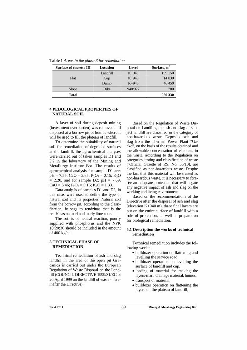
Table 1 Areas in the phase 3 for remediation Surface of cassette III Location Level Surface, m2
Flat Landfill K+940 199 150
Cup K+940 14 030 Dump K+940 46 450
Slope Dike 940/927 700 Total 260 330
4 PEDOLOGICAL PROPERTIES OF NATURAL SOIL
A layer of soil during deposit mining (investment overburden) was removed and disposed at a borrow pit of humus where it will be used to fill the plateau of landfill.
To determine the suitability of natural soil for remediation of degraded surfaces at the landfill, the agrochemical analyses were carried out of taken samples D1 and D2 in the laboratory of the Mining and Metallurgy Institute Bor. The results of agrochemical analysis for sample D1 are: pH = 7.55, CaO = 3.85; P2O5 = 0.15; K2O = 2.20, and for sample D2: pH = 7.69, CaO = 5.46; P2O5 = 0.16; K2O = 1.33.
Data analysis of samples D1 and D2, in this case, were used to define the type of natural soil and its properties. Natural soil from the borrow pit, according to the classi-fication, belongs to rendzinas that is the rendzinas on marl and marly limestone.
The soil is of neutral reaction, poorly supplied with phosphorus and the NPK 10:20:30 should be included in the amount of 400 kg/ha.
5 TECHNICAL PHASE OF REMEDIATION
Technical remediation of ash and slag landfill in the area of the open pit Gra-čanica is carried out under the European Regulation of Waste Disposal on the Land-fill (COUNCIL DIRECTIVE 1999/31/EC of 26 April 1999 on the landfill of waste - here-inafter the Directive).
Based on the Regulation of Waste Dis-
posal on Landfills, the ash and slag of sub-ject landfill are classified in the category of non-hazardous waste. Deposited ash and slag from the Thermal Power Plant ”Ga-cko”, on the basis of the results obtained and the allowable concentration of elements in the waste, according to the Regulation on categories, testing and classification of waste (''Official Gazette of RS, No. 56/10), are classified as non-hazardous waste. Despite the fact that this material will be treated as non-hazardous waste, it is necessary to fore-see an adequate protection that will negate any negative impact of ash and slag on the working and living environment.
Based on the recommendations of the Directive after the disposal of ash and slag (elevation K+940 m), three final layers are put on the entire surface of landfill with a role of protection, as well as preparation for biological remediation.
5.1 Description the works of technical remediation
Technical remediation includes the fol-lowing works:
bulldozer operation on flattening and levelling the service road,
bulldozer operation on levelling the surface of landfill and cup,
loading of material for making the layers-marl, drainage material, humus,
transport of material, bulldozer operation on flattening the
layers on the plateau of landfill,

No. 4, 2014 Mining & Metallurgy Engineering Bor 90
installation of drainage pipes and channels,
connecting the all parts of drainage system,
loading and transport of humus for remediation of slope (embankment).
Works on construction the service road
The service road will be constructed on the landfill plateau (Figure 5). The service road will be 5 m wide. The construction con-sists of flattening and levelling the ground with bulldozer.
Works on formation the final layer on the plateau of landfill
The material is taken from the formed landfills of marl, which are located near the
landfill, to set up the first layer on the land-fill plateau. Loading and transport of these materials are done on the landfill plateau. The work of mechanization on planning forms a layer of marl to height of 1 m (Fi-gure 4). In doing so, it is ensured that dou-ble-layer corrugated drainage pipes, Φ160 mm, are installed on predicted placers. These pipes are placed at distance of 80 m.
The function of these pipes is to collect water (weathering) and to drain the water to the sewers by the set drainage system. The all water in sewers is drained by gravity basin to the receiving manhole, and there the collected water via double-layer corrugated sewer pipes, Figure 5, is taken up to the ri-verbed. There it is discharged into the re-cipient.
Figure 4 Cross section of the landfill with view of all layers and service road
Figure 5 Cross section of the landfill with view of drainage system

No. 4, 2014 Mining & Metallurgy Engineering Bor 91
After unloading the material by truck, the planning of material is done by bull-dozer. In doing so, the care is taken that the planned surface has a drop of 1%.. Plateau is divided into sections of 80 m, Figure 6.
Each section has an appearance as shown in Figure 6, which shows drops of
this layer. In this way, the proper function-ing of drainage system is allowed. All collected water goes into the formed „channel” and from there the water is col-lected is the drainage pipe of Φ160 mm. This water is lowered down by the chan-nels into the main channel that was made between the service road and this layer.
Figure 6 View of the final layer segments
For the system functioning, it is nece-
ssary to form the first layer (marl) with a slight drop of 1% (drop is shown in Figure 6). In addition to the general decline, this layer is formed to have another drop towards ”inside”. As shown in Figure 6, a distance of 80 m on which the pipes will be placed, will be divided in half, where these halves will form a drop to inside ”inside”. and, by this way, all water will be lowered down to the pipes.
After completion the formation of the first layer, the formation of the second layer starts – so called drainage layer (Figure 4). The material that will be used for the prepa-ration of this layer consists of gravel, size 5-25 mm. Loading of this material will be made within the complex TPP Gacko. The investor does not own this material so that it is necessary to procure the same. In order to reduce the transport distance, the purchased materials will be disposed near the landfill
near that, i.e. the marl landfill. Thus it will be proceeded as the enough space will be created after utilization of material for form-ing the first layer, i.e. the layer of marl on landfill.
Transported material is deposited on piles by the newly formed layer as bulldozer could easily and quickly manipulate with it. For continuous operation of machinery at slopes of the newly formed layer of 1 m, a road will temporarily constructed in the cut, which will be turned back to the proper state after completion of works. Planning the de-posited material is also done by bull-dozers. The layer thickness is about 0.5 m.
The final layer is formed of humus. The temporary landfills are formed in the vicinity of the landfill, where the necessary quantity of humus will be transported to the landfill plateau. The layer thickness is about 1 m. Works on planning and levelling the final layer will be made by machinery - bulldozer.
No. 4, 2014 Mining & Metallurgy Engineering Bor 92
6 BIOLOGICAL PHASE OF OPTIMUM REMEDIATION
When reclamation of ash and slag land-fills is carried out using the biological meth-ods, the role of grasses that meet a number of conditions as pioneer plants in the devas-tated areas and soilless land is underlined. [11]. For those landfills reclamation, the selected plant species can be used that initi-ate a long-time biological renewal process. Their development prevents erosion and supports the process of soil formation.
Moreover, the use of woody plants eli-minates the possibility of consumption with yield of toxic or detrimental substances to humans and animals which can be taken in large quantities by certain plants species [13, 17].
For planting in the landfill and protective belt, the following species of trees and shrubs are recommended: Robinia psedu-dacaccia L., Betula verrucosa Ehrh., Alnus incana L., Alnus glutinosa Gaertn., Larix decidua Mill., Rosa rugosa Thunb., Populus robusta and serotina R. Hartig, Populus alba L., Salix purpurea L., Elaeagnus angustifolia L. and Tamarix gallica L. [14, 17].
The optimal phase of biological remedia-tion involves the application of phyto-ame-liorative measures on the substrate in order to establish and survival of vegetation to form a stable ecosystem. For the success of biological remediation, the previous works of agrotechnical and technical remediation are important as well as the implementation of measures of care and protection the cul
tures at all stages of their development. Se-lected cultures fit into the existing landscape and will contribute to more beautiful appear-ance of the micro location.
Taking into account the factors that in-fluence the biological remediation, pri-marily the substrate with physico-chemical properties, altitude and habitat conditions, there was not a great variety of cultures. It was decided that the application of afforesta-tion is the most suitable method of optimal biological phase of remediation on degraded areas of the landfill.
In selection of species for afforestation, their adaptation was taken into account to the conditions of the substrate, climate, good reception at planting and resistance to the action of the basic natural factors. The pio-neer species - acacia (lat. Robinia pseu-doacacia) was selected which has given the good results up to nowadays in reclamation the degraded areas with unfavorable condi-tions.
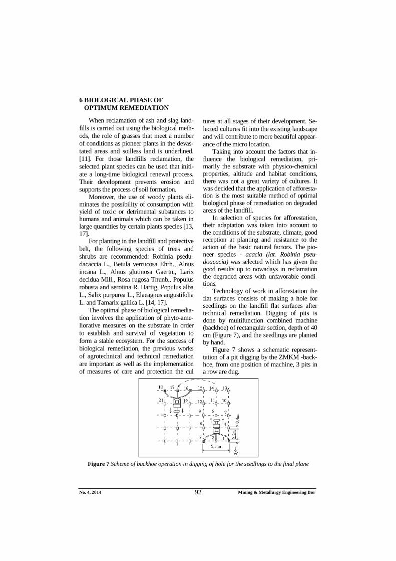
Technology of work in afforestation the flat surfaces consists of making a hole for seedlings on the landfill flat surfaces after technical remediation. Digging of pits is done by multifunction combined machine (backhoe) of rectangular section, depth of 40 cm (Figure 7), and the seedlings are planted by hand.
Figure 7 shows a schematic represent-tation of a pit digging by the ZMKM -back-hoe, from one position of machine, 3 pits in a row are dug.
Figure 7 Scheme of backhoe operation in digging of hole for the seedlings to the final plane

No. 4, 2014 Mining & Metallurgy Engineering Bor 93
The holes of seedlings are digged with a stroke of bucket clawing into the soil. Ac-cording to the measurements on the ground, from one position ZMKM-backhoe digs 3 holes for 90 s. If the time of digging includes also the machine moving, then digging time is 2 min. However, there are unforeseen delays as well as turning the machine at the end of the section. For this reason, it is as-sumed that the machine digs in an hour 60 holes for seedlings.
7 EFFECTS OF REMEDIATION THE ASH AND SLAG LANDFILL
Afforestation of degraded lands is pri-marily aimed to the preservation of the envi-ronment, breeding the landscape, deve-lopment of beekeeping and profit from the acacia wood. The root system of acacia is deep and binds substrate binds and stimu-lates t development of pedological processes [5]. Acacia species belongs to the biomelio-rative species - improves the soil properties and enables preparation for more economical species in the future [5].
Remediation effects of ash and slag land-fill are reflected in the fact that: Forest plantings provide better bon-
ding of soil, stimulate development of ground flora, activate pedological processes in the substrate by the root system, prevent insolation and drying of soil, blowing of strong winds and dust raising.
Afforestation of degraded areas on the ash and slag landfill contributes to the environmental protection, im-proving the microclimate and aest-hetic appearance of the environment.
Total degraded areas on landfills amount to 260,330 m2.
Total costs of remediation for 26,033 ha amount to: Ttotal = 1,577,125.64 € (dynamics of work 2 years).
Total price of remediation per one hec-tare amounts: 60,581.79 €/ha.
Total price of remediation per one m2 amounts: 6.057179 €/m2.
8 CONCLUSION
Wasted ash and slag, deposited on the landfill can be classified as disruptive and harmful to the environment. The available literature suggests that there are many plants that can be used for the reclamation of de-graded areas because they develop into bar-ren substrates very well, often contain toxic substances. In the case of the landfill of TPP Gacko, a pioneer species is adopted - acacia (lat. Robinia pseudoacacia), which has so far given the good results in reclamation of degraded areas with adverse conditions.
This work presents the method of opti-mum remediation and its effects that will have a positive impact on the environment.
REFERENCES
[1] I. Jovanović, M. Bugarin, S. Magda-linović: Review of Contemporary World Studies on Characteristics of Fly Ash as a Secondary Mineral Resource: Part 1; Mining and Metallurgy Engi-neering Bor 2/2013, pp. 147-156;
[2] Lj. Obradović, D. Urošević, G. Tomić: Physical Characterization of Ash and Slag from the Landfill in Medoševac; Mining Engineering, 1/2010, pp.57-68;
[3] Remediation of Degraded Areas at the Open Pit of Marl Trešnja Holcim Popovac, MMI Bor, Miomir Mikić, 2014 (in Serbian);
[4] Technical Project of Remediation the Ash and Slag Landfill, MMI IRM Bor, Miomir Mikić, June 2013 (in Serbian);
[5] M. Mikić, I. Jovanović, D. Urošević: Remediation the Ash and Slag Landfill Gacko – B&H, Mining and Metallurgy Engineering Bor, 1/2014, pp.105-112;

No. 4, 2014 Mining & Metallurgy Engineering Bor 94
[6] S. Krstić, M. Ljubojev, M. Mikić, V. Ljubojev: Methods of Geotechnical Investigations for Rehabilitation and Remediation the Flotation Tailing Dump Veliki Krivelj (Serbia), XIV Balkan Mineral Processing Congress, Proceedings, June, 2011, Tuzla, B&H pp. 851-853;
[7] D. Kržanović, M. Mikić, M. Ljubojev: Analysis the Spatial Position of Mining Facilities of the Veliki Krivelj Mine to the Proposed Tunnel Route for Relocation the Krivelj River, Mining Engineering, 3/2011, 2011, pp. 95-100;
[8] D. Kržanović, M. Mikić, M. Ljubojev: Analysis of Development Effects of the Veliki Krivelj Mine on Constru-ction the New Facilities for Deviation the Krivelj River, Mining Engineering 4/2011, 2011, pp. 57-65;
[9] M. Mikić, D. Kržanović, M. Ljubojev. Аuscultation and Zone Monitoring of Current Collector of the Кrivelj River below Flotation Tailing Dump "Veliki Krivelj", Serbia. 12th Scientific Geo-conference SGEM 2012, Proceedings, Volume I, Geology Exploration and Mining, Proceedings, 17-23 June, Albena Bulgaria, pp. 465-472;
[10] M. Ljubojev, D. Ignjatović, L. Djur-djevac-Ignjatović, V. Ljubojev, Preparations for Investigation the Tunnel Route and Field Surveying, Mining Engineering, No. 1, 2011, pp. 135-166;
[11] Żmuda K., Wiśniowska-Kielian B Industrial waste Landfills and Methods of their Reclamation, MENDELNET 2012, pp. 563-570;
[12] Antonkiewicz J. 2010. Właściwości fizykochemiczne odpadów przemy-słowych na składowiskach. Roczn. Glebozn., 61(3): 5-12;
[13] Antonkiewicz J. 2011. Ocena bio-dostępności metali ciężkich w odpa-dach zastosowanych do przyrodniczej rekultywacji składowiska odpadów niebezpiecznych. Zesz. Nauk UR w Krakowie, 484, Rozprawy 481, 131 p;
[14] Bender J., Gilewska M. 2004. Rekulty-wacja w świetle badań i wdrożeń. Roczn. Glebozn., 55(2): pp. 29-46;
[15] Klimont K. 2011. Rekultywacyjna efektywność osadów ściekowych na bezglebowym podłożu wapna poflo-tacyjnego i popiołów paleniskowych. Probl. Inż. Rol., 2: pp. 165-176;
[16] Łuniewski A., Łuniewski S. 2010. Od prymitywnych wysypisk do nowo-czesnych zakładów zagospodarowania odpadów. Wyd. Ekonomia i Środo-wisko, Białystok, pp. 159-162, 164, 172, 174-176, 179, 196-197;
[17] Maciak F. 1996. Ochrona i rekulty-wacja środowiska. Wyd. SGGW, Warszawa, pp. 120-122, 139, 141-144, 153, 259-266, 330, 334;
[18] Pyssa J. 2005. Odpady z energetyki – przemysłowe zagospodarowanie od-padów z kotłów fluidalnych. Gosp. Sur. Mineral., 21(3): pp. 83-92;
[19] Siuta J. 1998. Rekultywacja gruntów. Poradnik. IOŚ, Warszawa, p. 108-114;
[20] Woźniak M., Żygadło M. 2002. Moni-toring składowisk odpadów paleni-skowych. Regionalny Monitoring Środowiska Przyrodniczego, Kieleckie Towarzystwo Naukowe, 3: pp. 117-122.
Broj 4, 2014. Mining & Metallurgy Engineering Bor 95
INSTITUT ZA RUDARSTVO I METALURGIJU BOR ISSN: 2334-8836 (Štampano izdanje) UDK: 622 ISSN: 2406-1395 (Online)
UDK: 626.877:662:666.952(045)=163.41 DOI:10.5937/MMEB1404085M
Miomir Mikić*, Radmilo Rajković*, Daniela Urošević*, Ivana Jovanović*
REKULTIVACIJE DEPONIJE PEPELA I ŠLJAKE KASETA BR. III TE ''GACKO'' NAKON FAZE 3**
Izvod
Na kraju rada deponije, sva zemlja zahteva rekultivaciju pokretanjem procesa formiranja tla meliorisanog terena, ali pre svega obnove vegetacije izborom odgovarajućih vrsta biljnih kultura. Deponovanje pepela i šljake iz TE Gacko u Gacku, BiH vršilo se u kaseti II formiranoj u otkopnom prostoru površinskog kopa Gračanica. Sa potrebom novog prostora za deponovanje pepela i šljake nađeno je rešenje u formiranju kasete III u nastavku postojeće kasete II. Ovaj rad opisuje metodu rekultivacije koja će se izvršiti na kaseti III nakon završetka faze 3.
Ključne reči: rekultivacija, deponija, pepeo i šljaka
* Institut za rudarstvo i metalurgiju Bor **Rad je proizašao iz projekta broj TR 33021 „Istraživanje i praćenje promena naponsko defor-
macijskog stanja u stenskom masivu „in-situ“ oko podzemnih prostorija sa izradom modela sa posebnim osvrtom na tunel Kriveljske reke i Jame Bor“, koji je finansiran sredstvima Ministarstva zaprosvetu, nauku i tehnološki razvoj Republike Srbije
UVOD
U Tehnološkom procesu sagorevanja uglja u termoelektranama proizvodi odre-đene količine pepela i šljake koje treba trans-portovati i odložiti na izabranoj lokaciji – deponiji. Poteškoće u odlaganja otpada i korišćenja su rezultat trajnog povećanja mase otpada, kao i razvoja industrije i rudar-stva, a raznovrstan njihov kvalitet proizilazi iz raznolikosti industrijske proizvodnje [17]. U poslednjih nekoliko decenija industrijska aktivnost preduzeća izazvala je velike štete po životnu sredinu. Jedan od najvećih pro-blema je porast količine otpada. Da bi se smanjilo skladištenje, postaje neophodno intenziviranje u pravcu njihovog odlaganja i recikliranja [18]. U mnogim razvijenim zemljama otpad je vredan resurs koji ne samo da, ali mora biti ponovo iskorišćen, ako je cilj akcije smanjenje upotrebe pri-rodnih resursa. Ipak, trenutno znanje ne -
dozvoljava upotrebu svih generisanih otpada, tako da je skladištenje nezaobilazno [12].
Otpad deponovan u deponije često degradira veću površinu nego što direktno zauzima i može negativno uticati na priro-dnu sredinu zbog pojave procednih voda, gasova iz podzemnih emisija ili emisije pra-šine u atmosferu 11. Otpad takođe zagađu-ju površinske i podzemne vode, kao i zemlji-šta. Razumevanje fizičke i hemijske osobine industrijskog otpada će omogućiti izbor optimalnih metoda biološke rekultivacije deponije [20]. Upotreba pepela iz peći i karbidnog kreča je često ometana, što se uglavnom odnosi na nedostatak odgo-varajuće tehnologije prerade ovih materijala. Dakle, samo oko 30% pepela iz peći (uglavnom iz sagorevanja uglja) se koristi, a kreč se obično akumulira na odlagalištima.

Broj 4, 2014. Mining & Metallurgy Engineering Bor 96
Deponije industrijskog otpada
Deponije su objekti koji se koriste za skladištenje otpada na zemlji bez nepo-željnih efekata na životnu sredinu, kako za vreme rada tako i posle njegovog završetka. Takođe, one su deo sistema upravljanja otpadom, jer nije moguće da se iskoristi celokupna masa otpada [16].
Pri sagorevanju uglja u termoelektra-nama proizvodi se određena količine pepela i šljake koje treba transportovati, deponovati na određenoj lokaciji. Leteći pepeo pred-stavlja najfiniju frakciju koja zaostaje nakon sagorevanja uglja u termalnim postroje-njima. [1]. Leteći pepeo je heterogena meša-vina čestica različitih fizičkih, hemijskih, mineroloških i morfoloških osobina, koja nastaje sagorevanjem uglja u termoelektra-nama i čije su karakteristike određene kvali-tetom izgorelog uglja, tehnologijom sagore-vanja i uslovima sagorevanja. [1]. Fine frak-cije pepela mogu imati jak degradirajući uticaj na životnu sredinu i okolinu, posebno u periodu jakih vetrova, kada se raznose po okolini, što može dovesti do velikih ekolo-ških problema, a pre svega narušavanja zdravlja stanovništva, imajući u vidu da je ova sirovina kategorisana kao opasan otpad. [2]
U slučaju tehnogene sirovine koja se dobija iz TE Gacko, aerozagađenje je elimi-nisano, jer se transportuje na deponiju u vidu hidromešavine tj. u okvašenom, odnosno potopljenom stanju. [5] Naime, elektro-filterski pepeo iz TE Gacko pripada tipu karbonatnih pepela (visok sadržaj CaO), što znači da poseduje cementaciona svojstva i u kontaktu sa vodom gradi kompaktan materijal određene mehaničke čvrstoće. Na taj način sprečena je emisija finih čestica pepela u vazduh. [5].
Karakteristike deponije pepela i šljake u Gacku (Republika Srpska)
Termoelektrana Gacko (Republika Srpska) od 1995. g. odlaganje pepela vrši na deponiji pepela u kaseti I. Nakon dugo-
godišnjeg odlaganja pepela i šljake u kaseti I a zatim i kaseti II, došlo je do smanjenja odlagališnog prostora pa je bilo neophodno obezbediti novi prostor za deponovanje pepela i šljake i time obezbediti kontinualni rad TE Gacko. Adekvatno rešenje je nađeno u formiranju deponije u kaseti III, u otkop-nom prostoru površinskog kopa Gračanica.
Lokacija deponije i pepela u kaseti III je izabrano kao najpovoljnije tehno-eko-nomsko rešenje za odlaganje pepela i šljake iz TE Gacko s obzirom na lokaciju naselja Gacko, razvijene infrastrukture, raspolo-živosti prostora, i sl. Deponije pepela na kaseti III približno je pravougaonog oblika, dimenzija 515x265 m i jednim dodatkom dimenzija 210x130 m, (slika 1).
Nakon završetka faze 3 i dostizanja projektovane kote od K+940 mnv u kaseti III vrši se rekultivacija, čime se trajno eli-miniše bilo kakav negativni uticaj pepela iz deponije na okolni životni prostor i vazduh.
2. LOKACIJA DEPONIJE PEPELA I ŠLJAKE
Rudnik i Termoelektrana Gacko se na-laze u Gatačkom energetskom bazenu u jugoistočnom dijelu Republike Srpske. Termoelektrana je moćan i značajan ter-moenergetski proizvodni kapacitet sa go-dišnjom proizvodnjom i predajom u zajed-nički elektro-energetski sistem efektivnih 1.650.000.000 KWh električne energije.
Deponija pepela i šljake TE Gacko se nalazi na zapadnoj strani od grada Gacko i na udaljenosti od TE Gacko vazdušnom linijom oko 1.000 m. Sa zapadne strane je reka Gračanica a sa i jugoistočne strane je izmešteno korito reke Gračanice a sa jugo-zapadne strane je južna završna kontura po-lja „A“ odnosno korito rijeke Mušnice. Sa severne strane se nalaze unutrašnja i spoljašnja odlagališta laporca površinskog kopa Gračanica.
Broj 4, 2014. Mining & Metallurgy Engineering Bor 97
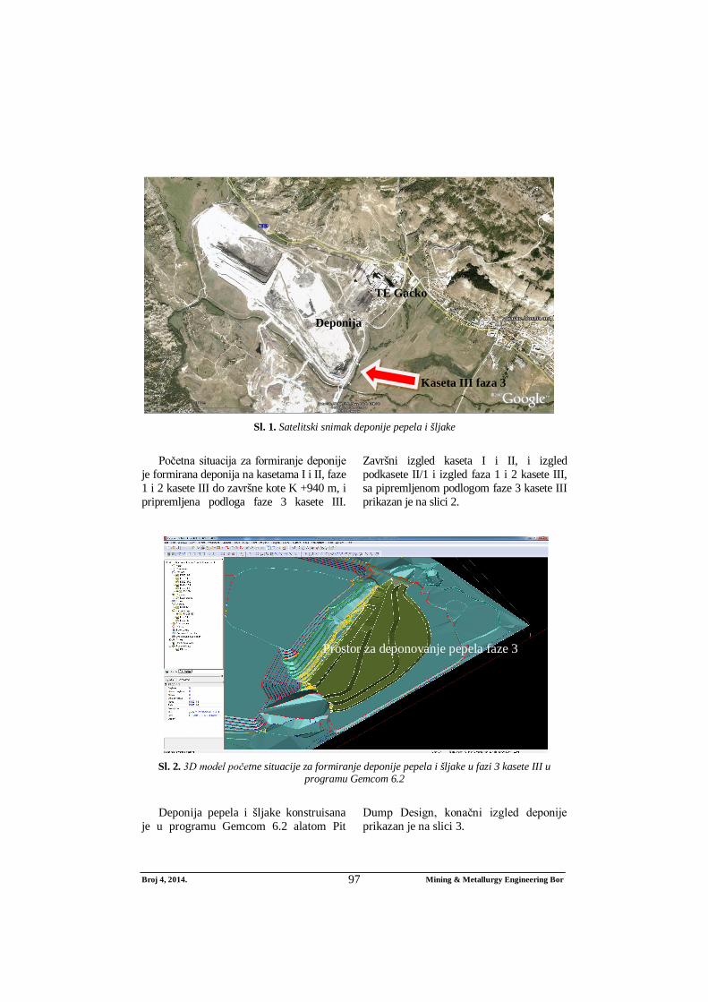
Sl. 1. Satelitski snimak deponije pepela i šljake
Početna situacija za formiranje deponije
je formirana deponija na kasetama I i II, faze 1 i 2 kasete III do završne kote K +940 m, i pripremljena podloga faze 3 kasete III.
Završni izgled kaseta I i II, i izgled podkasete II/1 i izgled faza 1 i 2 kasete III, sa pipremljenom podlogom faze 3 kasete III prikazan je na slici 2.
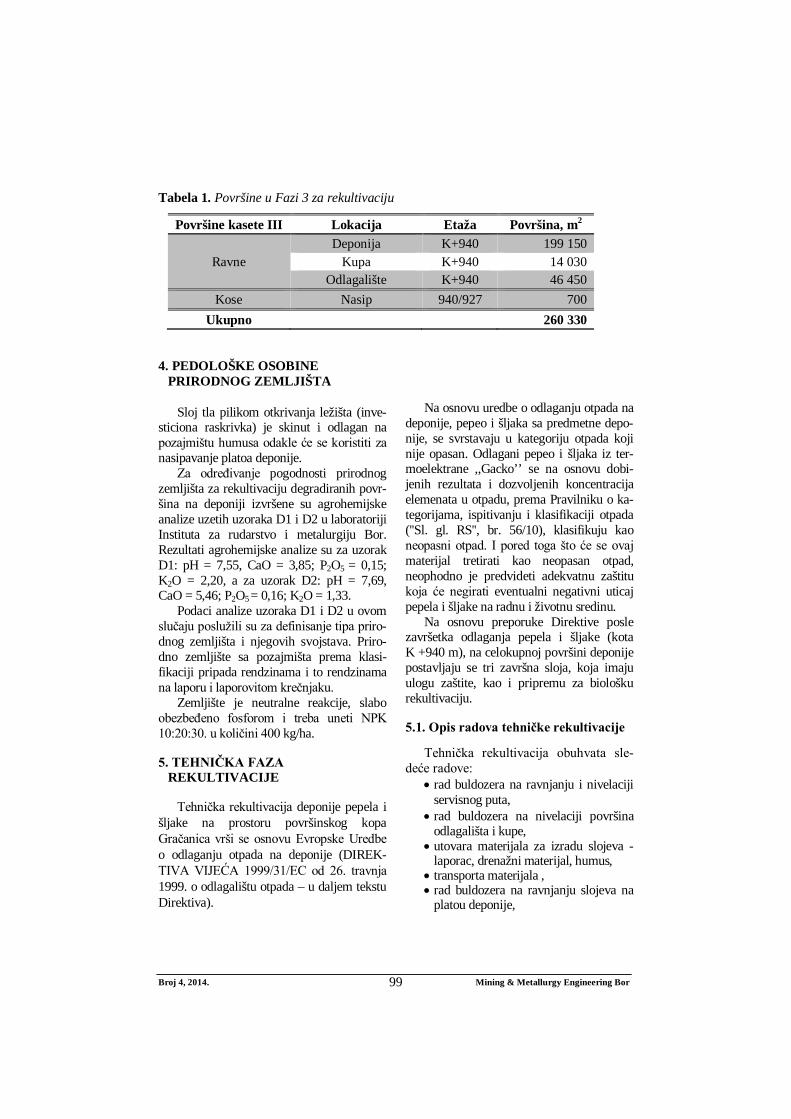
Sl. 2. 3D model početne situacije za formiranje deponije pepela i šljake u fazi 3 kasete III u
programu Gemcom 6.2
Deponija pepela i šljake konstruisana
je u programu Gemcom 6.2 alatom Pit Dump Design, konačni izgled deponije prikazan je na slici 3.
Deponija
Kaseta III faza 3
TE Gacko
Prostor za deponovanje pepela faze 3

Broj 4, 2014. Mining & Metallurgy Engineering Bor 98
Sl. 3. 3D model deponije pepela u fazi 3 kasete III u programu Gemcom 6.2
3. METODE REKULTIVACIJE DEPONIJE
Na kraju rada deponije, sva zemlja zah-teva rekultivaciju pokretanjem procesa for-miranja tla meliorisanog terena, ali pre svega obnove vegetacije izborom odgovarajućih vrsta biljnih kultura [15, 19]. Cilj remedija-cije je da se povrati upotrebna vrednost tla primenom odgovarajućih tehničkih, agrono-mskih i bioloških postupaka, omogućavajući korišćenje zemljišta za poljoprivredu, opšti-nske, šumarske svrhe, itd. [11].
Ponovno kultivisanje i revitalizaciju de-gradiranih površina nastalih ekploatacijom uglja na površinskom kopu Gračanica a kasnije deponovanjem pepela i šljake u otkopani prostor površinskog kopa podra-zumeva rekultivaciju.
Za revitalizaciju degradiranih površina na deponiji pepela i šljake, na kraju faze 3, primeniće se:
1. Tehnička faza optimalne rekulti-vacije uključuje:
a. otkopavanje, utovar, transport, i istovar humusa, drenažnog mate-rijala i laporca,
b. izradu servisnog puta, c. formiranje drenažnog sistema.
2. Biološka faza optimalne rekulti-vacije podrazumeva kompleks bio-tehničkih i fitomeliorativnih mera za uzgajanje šumskih kultura na depo-niji pepela i šljake u cilju obnavljanja ekosistema.
Prema fizičko hemijskim osobinama tla, geomorfologiji deponije, eksponiranost površina jugu, klimatskim uslovima i prior-dnoj vegetaciji u okruženju u obzir dolazi biološka faza optimalne rekultivacije sa pošumljavanjem degradiranih površina. Raspored vrsta po površinama prilikom po-šumljavanja vršena je na osnovu mikrosta-ničnih uslova.
Ukupne površine za rekultivaciju su date u tabeli 1
Deponija pepela faza 3 kasete III
Broj 4, 2014. Mining & Metallurgy Engineering Bor 99
Tabela 1. Površine u Fazi 3 za rekultivaciju
Površine kasete III Lokacija Etaža Površina, m2
Ravne Deponija K+940 199 150
Kupa K+940 14 030 Odlagalište K+940 46 450
Kose Nasip 940/927 700 Ukupno 260 330
4. PEDOLOŠKE OSOBINE PRIRODNOG ZEMLJIŠTA
Sloj tla pilikom otkrivanja ležišta (inve-sticiona raskrivka) je skinut i odlagan na pozajmištu humusa odakle će se koristiti za nasipavanje platoa deponije.
Za određivanje pogodnosti prirodnog zemljišta za rekultivaciju degradiranih povr-šina na deponiji izvršene su agrohemijske analize uzetih uzoraka D1 i D2 u laboratoriji Instituta za rudarstvo i metalurgiju Bor. Rezultati agrohemijske analize su za uzorak D1: pH = 7,55, CaO = 3,85; P2O5 = 0,15; K2O = 2,20, a za uzorak D2: pH = 7,69, CaO = 5,46; P2O5 = 0,16; K2O = 1,33.
Podaci analize uzoraka D1 i D2 u ovom slučaju poslužili su za definisanje tipa priro-dnog zemljišta i njegovih svojstava. Priro-dno zemljište sa pozajmišta prema klasi-fikaciji pripada rendzinama i to rendzinama na laporu i laporovitom krečnjaku.
Zemljište je neutralne reakcije, slabo obezbeđeno fosforom i treba uneti NPK 10:20:30. u količini 400 kg/ha.
5. TEHNIČKA FAZA REKULTIVACIJE
Tehnička rekultivacija deponije pepela i šljake na prostoru površinskog kopa Gračanica vrši se osnovu Evropske Uredbe o odlaganju otpada na deponije (DIREK-TIVA VIJEĆA 1999/31/EC od 26. travnja 1999. o odlagalištu otpada – u daljem tekstu Direktiva).
Na osnovu uredbe o odlaganju otpada na
deponije, pepeo i šljaka sa predmetne depo-nije, se svrstavaju u kategoriju otpada koji nije opasan. Odlagani pepeo i šljaka iz ter-moelektrane ,,Gacko’’ se na osnovu dobi-jenih rezultata i dozvoljenih koncentracija elemenata u otpadu, prema Pravilniku o ka-tegorijama, ispitivanju i klasifikaciji otpada (''Sl. gl. RS'', br. 56/10), klasifikuju kao neopasni otpad. I pored toga što će se ovaj materijal tretirati kao neopasan otpad, neophodno je predvideti adekvatnu zaštitu koja će negirati eventualni negativni uticaj pepela i šljake na radnu i životnu sredinu.
Na osnovu preporuke Direktive posle završetka odlaganja pepela i šljake (kota K +940 m), na celokupnoj površini deponije postavljaju se tri završna sloja, koja imaju ulogu zaštite, kao i pripremu za biološku rekultivaciju.
5.1. Opis radova tehničke rekultivacije
Tehnička rekultivacija obuhvata sle-deće radove:
rad buldozera na ravnjanju i nivelaciji servisnog puta,
rad buldozera na nivelaciji površina odlagališta i kupe,
utovara materijala za izradu slojeva - laporac, drenažni materijal, humus,
transporta materijala , rad buldozera na ravnjanju slojeva na
platou deponije,

Broj 4, 2014. Mining & Metallurgy Engineering Bor 100
postavljanje drenažnih cevi i kanaleta, povezivanje svih segmenata drenažnog
sistema, utovar i transport humusa za rekulti-
vaciju kosine (nasip).
Radovi na izgradnji servisnog puta
Servisni put će biti izgrađen na platou odlagališta (slika 5). Servisni put će biti širok 5 m. Sama izrada se sastoji od rav-njanja i nivelacije terena buldozerom.
Radovi na formiranju završnog sloja na platou deponije
Sa formiranih odlagališta laporca koji se nalaze u blizini deponije uzima se materijal
za postavljanje prvog sloja na platou depo-nije. Vrši se utovar i transport ovog mate-rijala na plato deponije. Radom meha-nizacije na planiranju formira se sloj laporca u visini od 1 m (slika 4). Pri tome se vodi računa da se na predviđenim mestima pos-tavljaju rebraste dvoslojne drenažne cevi Φ160 mm. Ove cevi se postavljaju na rasto-janju od 80 m.
Funkcija ovih cevi jeste da prikupljaju vodu (atmosferalije) i postavljenim siste-mom za drenažu odvode vodu do odvodnih kanala. Sva voda u odvodnim kanalima gra-vitacijski se sliva do prijemne šahte, odatle se prikupljena voda preko rebraste dvoslojne kanalizacione cevi, slika 5 odvodi do korita reke. Tu se ispušta u recipijent.
Sl. 4. Poprečni presek deponije sa prikazom svih slojeva i servisnog puta
Sl. 5. Poprečni presek deponije sa prikazom drenažnog sistema

Broj 4, 2014. Mining & Metallurgy Engineering Bor 101
Nakon istresanja materijala kamionom, prelazi se sa planiranjem materijala bul-dozerom. Pri tome se vodi računa da pla-nirana podloga ima pad 1 %. Plato je po-deljen na deonice od 80 m, slika 6.
Svaka deonica ima izgled prikazan na slici 6, na kojoj su prikazani padovi ovog
sloja. Na ovaj način se omogućuje pravilno funkcionisanje drenažnog sistema. Sva pri-kupljena voda odlazi u formirani ,,kanal’’ a odatle se voda skuplja sa drenažnom cevi Φ160 mm. Ova voda se kanaletama spušta u glavni kanal koji je izrađen između servis-nog puta i ovog sloja.
Sl. 6. Prikaz segmenta završnog sloja
Da bi sistem drenaže funkcionisao neop-
hodno je da se prvi sloj (laporac) formira sa blagim padom od 1 % (pad je prikazan na slici 6). Pored generalnog pada, ovaj sloj se formira da ima još jedan pad ka ,,unutra’’. Kako je prikazano na slici 6, rastojanje od 80 m na kojima će biti postavljene cevi, će se podeliti na pola, pri tome će ove polovine formirati pad ka ,,unutra’’ i na taj način će se sve vode slivati ka cevima.
Nakon završetka formiranja prvog sloja počinje se sa radom na formiranju drugog sloja – tzv. drenažnog sloja (slika 4). Mate-rijal koji će se primeniti za izradu ovog sloja sastoji se od šljunka veličine 5-25 mm. Utovar ovog materijala će se vršiti u okviru kompleksa TE Gacko. Investitor ne pose-duje ovaj materijal pa je neohodno da ga nabavi. Da bi se dužina transporta smanjila kupljeni materijal će se odložiti u blizini deponije tj. na odlagalištu laporca. Ovako će
se postupiti jer će se stvoriti dovoljno mesta nakon iskorišćenja materijala za formiranje prvog sloja tj. sloja laporca na deponiji.
Transportovani materijal se odlaže na gomile po novo formiranom sloju kako bi buldozer mogao da lakše i brže manipuliše sa njim. Da bi mehanizacija funkcionisala kontinualno po kosinama novoformiranog sloja od 1 m, će se privremeno napraviti put u useku koji će se nakon završetka radova vratiti u odgovarajuće stanje. Planiranje deponovanog materijala se takođe vrši bul-dozerima. Debljina sloja iznosi oko 0,5 m.
Završni sloj se formira od humusa. U blizini deponije su formirana privremena odlagališta humusa, odakle će se potrebna količina humusa transportovati do platoa deponije. Debljina sloja iznosi oko 1 m. Radovi na planiranje i nivelisanju zavr-šnog sloja će se vršiti mehanizacijom – buldozerom.
Broj 4, 2014. Mining & Metallurgy Engineering Bor 102
6. BIOLOŠKA FAZA OPTIMALNE REKULTIVACIJE
Kada se rekultivacija deponija pepela i šljake obavlja korišćenjem bioloških meto-da, uloga trava koje ispunjavaju niz uslova kao pionirskih biljaka uništenog zemljišta je podvučena. [11]. Za remedijaciju tih depo-nija, mogu se koristiti odabrane biljne vrste koje iniciraju dugogodišnji biološki proces obnavljanja. Njihov razvoj sprečava eroziju i podržava proces formiranja zemljišta.
Pored toga, upotreba drvenastih biljaka eliminiše mogućnost potrošnje sa prinosom od toksičnih ili štetnih materija na ljude i životinje koje mogu biti preduzete u velikim količinama pojedinih biljnih vrsta [13, 17].
Za sadnju na deponiji i u zaštitnom pojasu, preporučuje se sledeće vrste drveća i žbunja:. Robinia pseudoacaccia L., Betula verrucosa Ehrh., Alnus incana L., Alnus glu-tinosa Gaertn., Larix decidua Mill., Rosa rugosa Thunb., Populus robusta i serotina R. Hartig, Populus alba L., Salix pur-purea L., Elaeagnus angustifolia L. i Tamarix gallica L. [14, 17].
Biološka faze optimalne rekultivacije podrazumeva primenu fitomeliorativnih mera na supstratu u cilju uspostavljanja i opstanka vegetacije radi formiranja stabilnog ekosistema. Za uspeh biološke rekultivacije važni su prethodni radovi agrotehničke i tehničke rekultivacije kao i sprovođenje mera nege i zaštite podignutih kultura u
svim fazama njihovog razvoja. Izabrane kulture se uklapa u postojeći pejzaž i dopri-nosiće lepšem izgledu mikrolokacije.
Uzimajući u obzir faktore koji utiču na bilošku rekultivaciju, a pre svega podloga sa fizičko-hemijskim osobinama, nadmorska visina i uslove staništa, nije postojao veliki izbor kultura. Odlučeno je da se kao najpo-voljnija metoda biološke faze optimalne rekultivacije na degradiranim površinama deponije primeni pošumljavanje.
Za izbor vrsta za pošumljavanje vodilo se računa o njihovom prilagođavanju uslo-vima podloge, klime, dobrom prijemu pri sadnji i otpornosti na delovanje osnovnih prirodnih faktora. Izabrana je pionirska vrsta – bagrem (lat. Robinia pseudoacacia), koja je dosad dala dobre rezultate pri rekultivaciji na degradiranim površinama sa nepovoljnim uslovima.
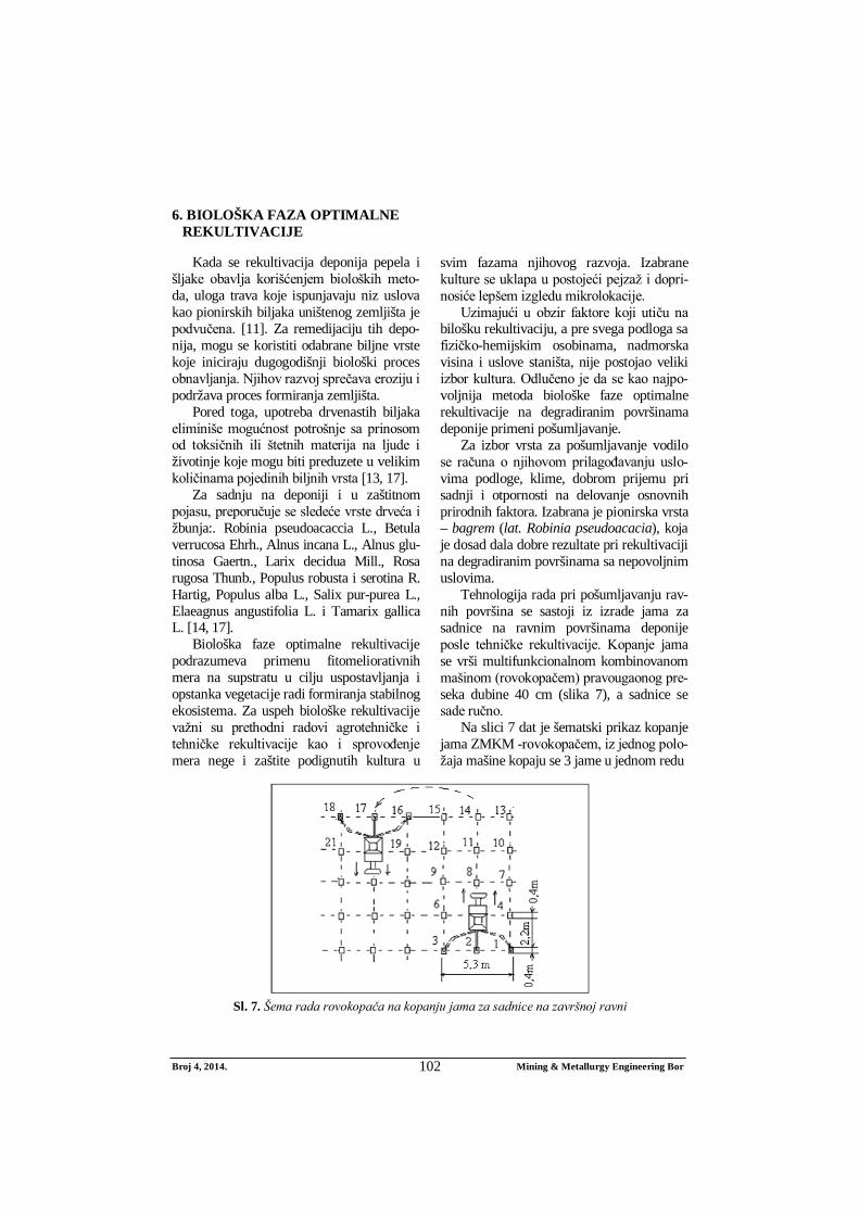
Tehnologija rada pri pošumljavanju rav-nih površina se sastoji iz izrade jama za sadnice na ravnim površinama deponije posle tehničke rekultivacije. Kopanje jama se vrši multifunkcionalnom kombinovanom mašinom (rovokopačem) pravougaonog pre-seka dubine 40 cm (slika 7), a sadnice se sade ručno.
Na slici 7 dat je šematski prikaz kopanje jama ZMKM -rovokopačem, iz jednog polo-žaja mašine kopaju se 3 jame u jednom redu
Sl. 7. Šema rada rovokopača na kopanju jama za sadnice na završnoj ravni

Broj 4, 2014. Mining & Metallurgy Engineering Bor 103
Jame sadnica se kopaju jednim potezom
zarivanja kašike u tlo. Prema merenjima na terenu iz jednog položaja ZMKM-rovo-kopač iskopa 3 jame za 90 s. Ako se u vreme kopanja uračuna i pomeranje mašine onda vreme kopanja iznosi 2 min. Međutim, postoje i nepredviđeni zastoji kao i okretanje mašine na kraju deonice. Iz tog razloga usvojeno je da za jedan sat mašinski se iskopa 60 jama za sadnice.
7. EFEKTI REKULTIVACIJE DEPONIJE PEPELA I ŠLJAKE
Pošumljavanje degradiranih površina na prvom mestu ima za cilj očuvanje životne okoline, oplemenjivanje pejzaža, razvoj pče-larstva i dobit od bagremove šume. Korenov sistem bagrema se duboko zakorenjuje i vezuje supstrat i podstiče razvijanje pedo-loških procesa. [5] Bagrem pripada biome-liorativnoj vrsti - popravlja svojstvo zemlji-šta i omogućava pripremu sredine za ekono-mičniju vrstu u budućem periodu [5].
Efekti rekultivacije deponije pepela i šljake ogledaju se u tome da: Šumski zasadi omogućavaju bolje
vezivanje zemljišta, stimulišu razvoj prizemne flore, aktiviraju pedološke procese u supstratu korenovim siste-mom, sprečavaju insolaciju i sušenje tla, duvanje jakih vetrova i podizanje prašine.
Pošumljavanjem degradiranih povr-šina na deponiji pepela i šljake dopri-nosi se zaštiti životne sredine, pobolj-šavanju mikroklime i estetskom izg-ledu okoline.
Ukupne degradirane površine na odlaga-lištima iznosi 260.330 m2.
Ukupni troškovi rekultivacije za 26,033 ha iznose: Tu= 1.577.125,64 € (dinamika rada 2 godine).
Ukupna cena rekultivacije po jednom hektaru iznosi: 60.581,79 €/ha.
Ukupna cena eurekultivacije po jednom m2 iznosi: 6,058179 €/m2.
8. ZAKLJUČAK
Otpadni pepeo i šljaka deponovani na deponiji mogu se klasifikovati kao reme-tilački i štetni za životnu sredinu. Dostupna literatura sugeriše da postoje mnoge biljke koje se mogu koristiti za remedijaciju degra-diranih površina jer se one razvijaju veoma dobro u jalovim podlogama koje često sadrže toksične materije.
U slučaju deponije TE Gacko usvojena je pionirska vrsta – bagrem (lat. Robinia pseudoacacia), koja je dosad dala dobre rezultate pri rekultivaciji na različitim degra-diranim površinama sa nepovoljnim uslo-vima.
U radu je prikazana metoda optimalne rekultivacije kao i njeni efekti koji će pozi-tivno uticati na životnu sredinu.
LITERATURA
[1] I. Jovanović, M. Bugarin, S. Magdali-nović: Pregled savremenih svetskih istraživanja o karakteristikama letećeg pepela kao sekundarne mineralne sirovine; deo 1, Mining and Metallurgy Engineering Bor, 2/2013, str. 157-166.
[2] Lj. Obradović, D. Urošević, G. Tomić: Fizička karakterizacija pepela i šljake sa deponije u Medoševcu, Rudarski radovi 1/2010, str. 57-68.
[3] Rekultivacija degradiranih površina na površinskom kopu laporca Trešnja Holcim Popovac, IRM Bor, M. Mikić, 2014
[4] Tehnički projekat rekultivacije depo-nije pepela i šljake, IRM Bor, M. Mi-kić, Jun 2013.
[5] M. Mikić, I. Jovanović, D. Urošević: Rekultivacija deponije pepela i šljake Gacko – BiH, Mining and Metallurgy Engineering Bor, 1/2014, str. 113-120.
Broj 4, 2014. Mining & Metallurgy Engineering Bor 104
[6] S. Krstić, M. Ljubojev, M. Mikić, V. Ljubojev: ,,Methods of geotechnical investigations for rehabilitation and remediation the flotation tailing dump Veliki Krivelj (Serbia)“, XIV Balkan mineral processing congress, Procee-dings, Jun, 2011, Tuzla, BIH, str. 851-853.
[7] D. Kržanović, M. Mikić, M. Ljubo-jev: Analiza prostornog položaja rud-ničkih objekata rudnika Veliki Krivelj u odnosu na predloženu trasu tunela za izmeštanje Kriveljske reke, Rudarski radovi, 3/2011, str. 89-94
[8] D. Kržanović, M. Mikić, M. Ljubojev: Analiza uticaja razvoja rudnika Veliki Krivelj na izgradnju novih objekata za devijaciju Kriveljske reke, Rudarski radovi, 4/2011, str. 49-56
[9] M. Mikić, D. Kržanović, M. Ljubojev. Аuscultation and zone monitoring of current collector of the Кrivelj river below flotation tailing dump "Veliki Krivelj", Serbia. 12th Scientific Geo-conference SGEM 2012, proceedings volume I, Geology Exploration and Mining. Proceedings, 17-23th June, Albena Bulgaria. str. 465-472.
[10] M. Ljubojev, D. Ignjatović, L. Djur-djevac Ignjatović, V. Ljubojev, Prepa-rations for Investigation the Tunnel Route and Field Surveying, Mining Engineering Journal, No. 1, 2011, str. 135-166.
[11] Żmuda K., Wiśniowska-Kielian B Industrial waste landfills and methods their reclamation, MENDELNET 2012, (563-570)
[12] Antonkiewicz J. 2010. Właściwości fizykochemiczne odpadów przemy-słowych na składowiskach. Roczn. Glebozn., 61(3): str. 5-12.
[13] Antonkiewicz J. 2011. Ocena bio-dostępności metali ciężkich w odpa-dach zastosowanych do przyrodniczej rekultywacji składowiska odpadów niebezpiecznych. Zesz. Nauk UR w Krakowie, 484, Rozprawy 481, 131 p.
[14] Bender J., Gilewska M. 2004. Rekul-tywacja w świetle badań i wdrożeń. Roczn. Glebozn., 55(2): str. 29-46.
[15] Klimont K. 2011. Rekultywacyjna efektywność osadów ściekowych na bezglebowym podłożu wapna poflo-tacyjnego i popiołów paleniskowych. Probl. Inż. Rol., 2: str. 165-176.
[16] Łuniewski A., Łuniewski S. 2010. Od prymitywnych wysypisk do nowo-czesnych zakładów zagospodarowania odpadów. Wyd. Ekonomia i Śro-dowisko, Białystok, str. 159-162, 164, 172, 174-176, 179, 196-197.
[17] Maciak F. 1996. Ochrona i rekul-tywacja środowiska. Wyd. SGGW, Warszawa, p. 120-122, 139, 141-144, 153, 259-266, 330, 334.
[18] Pyssa J. 2005. Odpady z energetyki – przemysłowe zagospodarowanie odpadów z kotłów fluidalnych. Gosp. Sur. Mineral., 21(3): str. 83-92.
[19] Siuta J. 1998. Rekultywacja gruntów. Poradnik. IOŚ, Warszawa, p. 108-114.
[20] Woźniak M., Żygadło M. 2002. Moni-toring składowisk odpadów paleni-skowych. Regionalny Monitoring Środowiska Przyrodniczego, Kieleckie Towarzystwo Naukowe, 3: str. 117-122.