KeV Harmonics from Solid Targets - The Relatvisitic Limit and Attosecond pulses Matt Zepf Queens...
26
keV Harmonics from Solid Targets - The Relatvisitic Limit and Attosecond pulses Matt Zepf Queens University Belfast Dromey et al. Queen’s University Belfast Krushelnick et al, Imperial College Norreys et al, RAL
-
date post
21-Dec-2015 -
Category
Documents
-
view
213 -
download
0
Transcript of KeV Harmonics from Solid Targets - The Relatvisitic Limit and Attosecond pulses Matt Zepf Queens...

keV Harmonics from Solid Targets -
The Relatvisitic Limit and Attosecond pulses
Matt Zepf
Queens University Belfast
B.Dromey et al. Queen’s University BelfastK. Krushelnick et al, Imperial CollegeP. Norreys et al, RAL

Outline
High Harmonic Generation from Solid Targets
Harmonics from solid targets – Background
Experimental resultsThe relativistic limit – high conversion efficiencieskeV harmonics – coherent fs radiationAngular distribution- beamed keV radiation
Potential for very bright attosecond pulse generation

Ultra High Harmonic Generation - the principle
• High power pulse tightly focused onto a solid target
• Critical surface oscillates with v approaching cRelativistically oscillating mirror = (1+(a0)2/2)1/2
• Reflected waveform is modified from sine to ~sawtooth
Incident Pulse
Reflected Pulse
Process intrinsically phased locked for all harmonics!
Zeptosecond pulses possible at keV
Harmonic efficiency is FT of reflected waveformTrain of as pulses (analogous to mode-locking)

Typical spectra – Conversion efficiency follows power law scaling
Conversion efficiency scales
q~n-p
With p=5.5…3.3 forI=5 1017…1019Wcm-2
(a0=0.6 .. 3)
Very high orders become rapidly more efficient at high intensitiese.g. 100th harmonic~I3
From Norreys, Zepf et al., PRL, 1832 (1996)
PIC predicts q~n-2.5 >1020Wcm-2. (a0>10) and 1000s of orders
0.01
0.1
1
10
100
1000
10 100 1000 10000
Pu
lse
du
rati
on
(as
)
nF
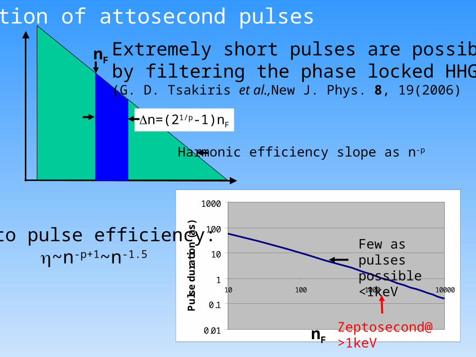
Duration of attosecond pulses
n=(21/p-1)nF
Few as pulsespossible <1keV
Zeptosecond@>1keV
nFExtremely short pulses are possible by filtering the phase locked HHG(G. D. Tsakiris et al.,New J. Phys. 8, 19(2006)
Harmonic efficiency slope as n-p
Atto pulse efficiency:~n-p+1~n-1.5

Realistic experimental configuration
Filters (~0.1µm thick) have negligible dispersion
(G. D. Tsakiris et al.,New J. Phys. 8, 19(2006)

Consequences from the oscillating mirror model
Oscillating Mirror
Flat, sharply defined critical density surface
• Flatness results in specular
reflection of the harmonics
• Well defined mirror surfacegives high conversion efficiency Phase locked harmonics – as pulses possible
Surface denting/bowing in response to laser can change collimation.Surface roughness important for Ångstrom radiation.
Harmonic efficiency depends strongly on plasma scale length, L
L/ 0.1-0.2
Short, high contrast pulses appear ideal.
Single cycle pulses to generate atto pulses

Experimental Setup:
CCD or image plate detectors
Grating spectrometer or von Hamos crystal spectrometer
Target position
Double plasma Mirror Setup
Incident laser pulse: f3 cone
Pulse Energy: up to 500JPulse energy with PM:up to 150 JPulse duration: 500-600fsContrast (no PM) >107:1Contrast with PMs: >1011:1Peak intensity (with PM) 2.5 1020Wcm-2

Experimental data from Vulcan PW shows p=2.5.2 for a=10
HIGH EFFICIENCY10-4@60 eV (17nm)10-6@250eV (4nm)
Extremely high photon numbersand brightness:
10131 photons10231ph s-1mrad-2 (0.1%BW)
Relativistic scaling pREL=2.5
Published: B. Dromey et al, Nature Physics, 2006
10
1
10-1
10-2
Inte
nsit
y/
/arb
. unit
sN
orm
alis
ed
at
1200
th
ord
er
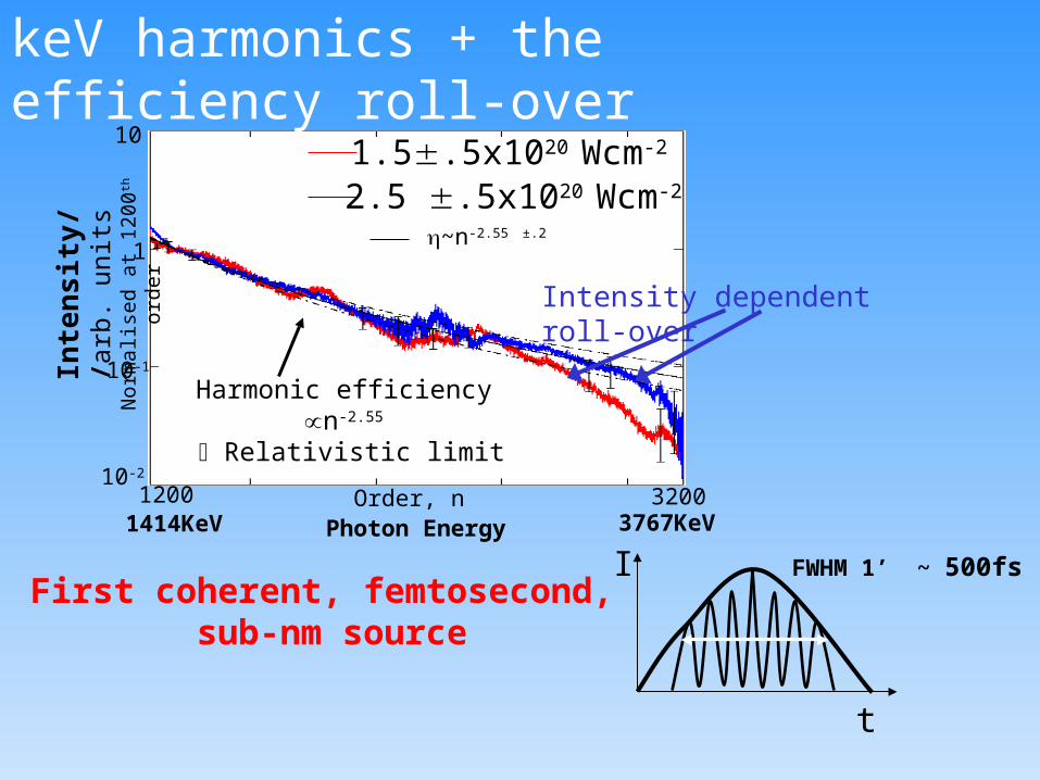
Order, n1200 3200
2.5 .5x1020 Wcm-2
1.5.5x1020 Wcm-2
Harmonic efficiency n-
2.55
Relativistic limit
~n-2.55 ±.2
Photon Energy1414KeV 3767KeV
Intensity dependent roll-over
keV harmonics + the efficiency roll-over
First coherent, femtosecond, sub-nm source
I
t
FWHM 1’ ~ 500fs
1
10
100
1000
10000
1 10 100
a0
Ro
ll-o
ver
po
siti
on
(o
rder
n)
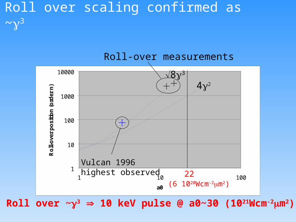
Roll over scaling confirmed as ~3
83
4
22
Roll-over measurements
Vulcan 1996highest observed
(6 1020Wcm-2m2)
Roll over ~3 10 keV pulse @ a0~30 (1021Wcm-2m2)
1
0.8
0.6
0.4
0.2 7x10¹⁹Wcm-2
2.5x10²⁰Wcm-2
Inte
nsit
y/
arb
. unit
s
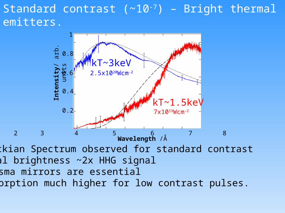
Wavelength /Å2 3 4 5 6 7 8
kT~1.5keV
kT~3keV
Standard contrast (~10-7) – Bright thermal emitters.
Planckian Spectrum observed for standard contrastSignal brightness ~2x HHG signalPlasma mirrors are essentialAbsorption much higher for low contrast pulses.
1
0.8
0.6
0.4
0.2
-100 50 0 50 100 150
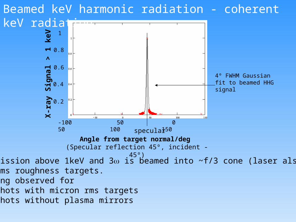
Angle from target normal/deg (Specular reflection 45º, incident -45º)
X-r
ay S
ign
al >
1 k
eV
4º FWHM Gaussian fit to beamed HHG signal
specular
Beamed keV harmonic radiation - coherent keV radiation
X-ray emission above 1keV and 3 is beamed into ~f/3 cone (laser also f/3) for nm rms roughness targets.No beaming observed for
-shots with micron rms targets-shots without plasma mirrors

Surface denting
Ponderomotive pressure can deform surface. (under the current conditions some deformation is unavoidableDenting required to explain our results:~ 0.1m
This would lead to the same divergence for all harmonics in agreement with results.
Solution: use shorter pulses to prevent surface deformation
Laser

• Harmonics from solids are efficient way of producing as pulses up to keV photon energies.
•Ideal for converting ultra high power pulses (100’s of TW)
•HHG in the relativistic limit has been demonstrated.
• Simple geometry for as-pulse production (surface harmonics, phase locked with flat phase, dispersion free system)
•Two possible schemes: polarisation switching or single cycle pulses
•Angular divergence limit remains a question mark: have we reached DL performance?
•Contrast requirements (>1010) are a challenge for fs lasers
Summary

Surface roughness
Laser
Surface roughness would impact on the highest orders only-Unlikely to be a major factor in this experiment
Solution: highly polished targets

Imprinted phase aberration
Phase errors in fundamental beam are passed on to harmonics
n~n Laser
Divergence of harmonics can be strongly affected (cf doubling of high power laser beams)
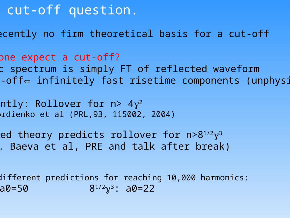
The cut-off question.
Until recently no firm theoretical basis for a cut-off
Should one expect a cut-off?Harmonic spectrum is simply FT of reflected waveformno cut-off infinitely fast risetime components (unphysical)
Recently: Rollover for n> 42 (Gordienko et al (PRL,93, 115002, 2004)
Revised theory predicts rollover for n>81/23
(T. Baeva et al, PRE and talk after break)
Very different predictions for reaching 10,000 harmonics:
42: a0=50 81/23: a0=22

What determines the angular distribution?
2) Why do keV harmonics beam at all?Surface roughness should prevent beaming(Wavelength<< initial surface roughness for keV harmonics)what reduces the surface roughness
a) smoothing in the expansion phase?b) Relativistic length contraction (highest harmonics are only generatedat max. surface )
1) What determines the angular distribution?Diffraction limited peformance would suggest harmonic~Laser/n harmonic~10-4 rad for keV harmonics.
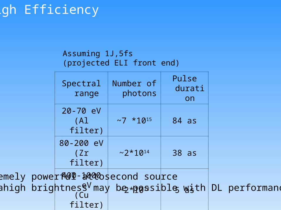
High Efficiency
Spectral range
Number of photons
Pulse duration
20-70 eV(Al filter)
~7 *1015 84 as
80-200 eV(Zr filter)
~2*1014 38 as
400-1000 eV(Cu filter)
~2*1012 5 as
Assuming 1J,5fs(projected ELI front end)
Extremely powerful attosecond sourceUltrahigh brightness may be possible with DL performance

Experimental paramters
Pulse Energy (No Plasma Mirror):up to 500JPulse energy with PM: up to 150 JPulse duration: 500-600fsContrast (no PM) >107:1Contrast with PMs: >1011:1Spot size: ~7mPeak intensity (with PM) 2.5 1020Wcm-2

Attosecond pulses by spectral filtering
Removing optical harmonics + fundamental changes wave from from saw-tooth to individual as-pulses and sub-as pulsesfrom (G. D. Tsakiris et al.,New J. Phys. 8, 19(2006)
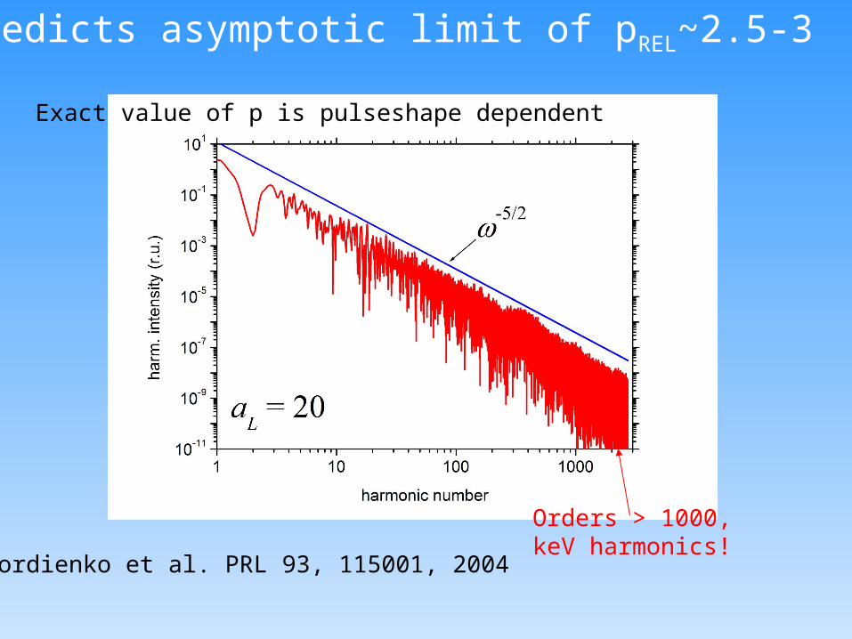
PIC predicts asymptotic limit of pREL~2.5-3
Orders > 1000,keV harmonics!
Exact value of p is pulseshape dependent
Gordienko et al. PRL 93, 115001, 2004

Conversion efficiency into attosecond pulses
Conv eff at filter peak: f|~(nf)-p
Bandwidth: n~(21/p-1)nF
Pulse efficiency: pulse~(21/p-1)nF-(p-1)~n-3/2
1.00E-07
1.00E-06
1.00E-05
1.00E-04
1.00E-03
1.00E-02
1.00E-01
1.00E+00
1 10 100 1000 10000
Centre frequency (n)
Co
nv
ers
ion
eff
icie
nc
y
~n-3/2
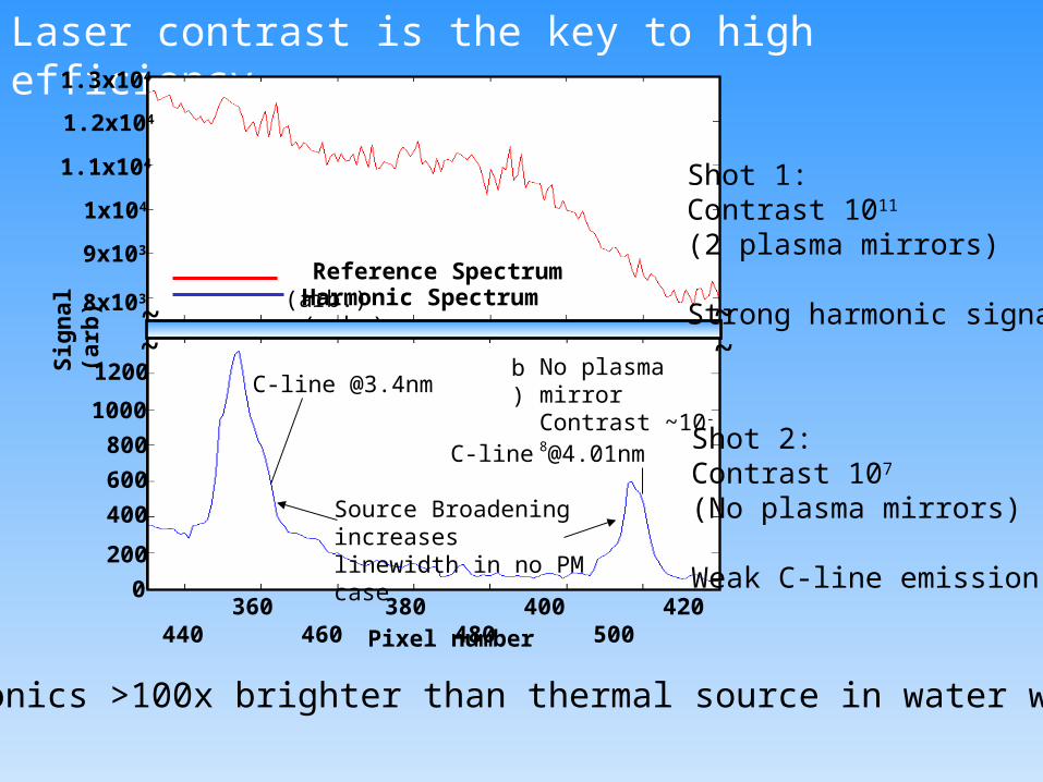
Laser contrast is the key to high efficiency.
360 380 400 420 440 460 480 500
Harmonic Spectrum (arb.) Reference Spectrum (arb.)
Pixel number
C-line @3.4nm
C-line @4.01nm
9x10³
1x10⁴
1.1x10⁴
1.3x10⁴
0
1.2x10⁴
~
200
~No plasma mirrorContrast ~10-8
Source Broadening increaseslinewidth in no PM case
Sig
nal
(ar
b)
b)
~~
8x10³
400
600
800
1000
1200
Shot 1:Contrast 1011
(2 plasma mirrors)
Strong harmonic signal.
Shot 2:Contrast 107
(No plasma mirrors)
Weak C-line emission
Harmonics >100x brighter than thermal source in water window