Kennametal Twist Drills
12
H613 Solid Carbide Drills Combination Tools Modular Drills Indexable Drills QPV Drills Twist Drills/ Taps & Dies Counterboring Tools Rotating Boring Tools Holemaking Tech Data Special Tooling/ Adapters Toolholding Systems Index axis—The imaginary straight line that forms the longitudinal centerline of a drill. backtaper—A slight decrease in diameter from front to back in the body of a drill. body—The portion of a drill extending from the shank or neck to the outer corners of the cutting lips. body clearance diameter—The portion of the land that has been cut away so it will not bind against the walls of the hole. chisel edge—The edge at the end of the web that connects the cutting lips. chisel edge angle—The included angle between the chisel edge and cutting lip, as viewed from the end of a drill. clearance diameter—The diameter over the cut-away portion of the drill lands. drill—A rotary end cutting tool having one or more cutting lips, and having one or more helical or straight flutes for the passage of chips and the admission of a cutting fluid. drill diameter—The diameter over the margins of a drill measured at the point. feeds—Feed rates for drilling are governed by the drill diameter, machinability of materials, and depth of hole. Small drills, harder materials, and deeper holes require additional considerations in selecting the proper feed rates. flute length—The length from the outer corners of the cutting lips to the extreme back of the flutes. Includes the sweep of the tool used to generate the flutes and therefore does not indicate the usable length of flutes. flutes—Helical or straight grooves cut or formed in the body of a drill that provide cutting lips, permit removal of chips, and allow cutting fluid to reach the cutting lips. helix angle—The angle formed by the leading edge of the land with a plane containing the axis of a drill. ipm—ipr x rpm = feed rate in inches per minute ipr—inches per revolution land—The peripheral portion of the body between adjacent flutes. land width—The distance between the leading edge and heel of the land; measured at a right angle to the leading edge. lead—The axial advance of a leading edge of the land in one turn around the circumference. lip relief angle—The axial relief angle at the outer corner of the lip; measured by projection to a plane tangent to the periphery at the outer corner of the lip. lips—The cutting edges of a two-flute drill extending from the chisel edge to the periphery. margin—The cylindrical portion of the land, which is not cut away, to provide clearance. neck—The section of reduced diameter between the body and the shank of a drill. overall length—The length from the extreme end of the shank to the outer corners of the cutting lip. It does not include the conical shank end often used on straight shank drills, nor the conical cutting point used on both straight and taper shank drills. point—The cutting end of a drill, made up of the ends of the lands and the web. In form, it resembles a cone, but departs from a true cone to furnish clearance behind the cutting lips. • conventional—Conventional points with 118° included point angles are the most commonly used because they provide satisfactory results in a wide variety of materials. A possible limitation is that the straight chisel edge contributes to walking at the drill point, often making it necessary to spot the hole for improved accuracy. Parts of the Technical Section were reprinted from the Metal Cutting Tool Handbook with permission from United States Cutting Tool Institute. (Continued on next page.) tang tang drive neck axis taper shank shank diameter straight shank shank length helix angle point angle drill diameter chisel edge angle lip relief angle overall length flutes margin body lip web flute length land body clearance diameter Kennametal Twist Drills KHSS Drill Dictionary
Transcript of Kennametal Twist Drills
H613
Solid
Car
bide
Drill
sCo
mbi
natio
nTo
ols
Mod
ular
Dril
lsIn
dexa
ble
Drill
sQP
VDr
ills
Twist
Dril
ls/Ta
ps &
Dies
Coun
terb
orin
gTo
ols
Rota
ting
Borin
gTo
ols
Hole
mak
ing
Tech
Dat
aSp
ecia
l Too
ling/
Adap
ters
Tool
hold
ing
Syste
ms
Inde
x
axis—The imaginary straight line that forms the longitudinal centerline of a drill.
backtaper—A slight decrease in diameter from front to back in thebody of a drill.
body—The portion of a drill extending from the shank or neck to theouter corners of the cutting lips.
body clearance diameter—The portion of the land that has been cutaway so it will not bind against the walls of the hole.
chisel edge—The edge at the end of the web that connects the cutting lips.
chisel edge angle—The included angle between the chisel edge andcutting lip, as viewed from the end of a drill.
clearance diameter—The diameter over the cut-away portion of thedrill lands.
drill—A rotary end cutting tool having one or more cutting lips, andhaving one or more helical or straight flutes for the passage of chipsand the admission of a cutting fluid.
drill diameter—The diameter over the margins of a drill measured at the point.
feeds—Feed rates for drilling are governed by the drill diameter,machinability of materials, and depth of hole. Small drills, harder materials, and deeper holes require additional considerations inselecting the proper feed rates.
flute length—The length from the outer corners of the cutting lips tothe extreme back of the flutes. Includes the sweep of the tool used togenerate the flutes and therefore does not indicate the usable lengthof flutes.
flutes—Helical or straight grooves cut or formed in the body of a drillthat provide cutting lips, permit removal of chips, and allow cutting fluidto reach the cutting lips.
helix angle—The angle formed by the leading edge of the land with aplane containing the axis of a drill.
ipm—ipr x rpm = feed rate in inches per minute
ipr—inches per revolution
land—The peripheral portion of the body between adjacent flutes.
land width—The distance between the leading edge and heel of theland; measured at a right angle to the leading edge.
lead—The axial advance of a leading edge of the land in one turnaround the circumference.
lip relief angle—The axial relief angle at the outer corner of the lip;measured by projection to a plane tangent to the periphery at theouter corner of the lip.
lips—The cutting edges of a two-flute drill extending from the chiseledge to the periphery.
margin—The cylindrical portion of the land, which is not cut away, toprovide clearance.
neck—The section of reduced diameter between the body and theshank of a drill.
overall length—The length from the extreme end of the shank to theouter corners of the cutting lip. It does not include the conical shankend often used on straight shank drills, nor the conical cutting pointused on both straight and taper shank drills.
point—The cutting end of a drill, made up of the ends of the landsand the web. In form, it resembles a cone, but departs from a truecone to furnish clearance behind the cutting lips.
• conventional—Conventional points with 118° included point angles are the most commonly used because they provide satisfactory results in a wide variety of materials. A possible limitation is that the straight chiseledge contributes to walking at thedrill point, often making it necessary to spot the hole forimproved accuracy.Parts of the Technical Section were reprinted from the Metal Cutting Tool Handbook
with permission from United States Cutting Tool Institute.(Continued on next page.)
tangtang drive
neck
axis
taper shank
shankdiameter
straightshank
shanklength
helix angle
point angle
drill diameter
chiseledge anglelip relief
angle
overall length
flutes
marginbody
lipwebflute length lan
d
body clearancediameter
Kennametal Twist DrillsKHSS Drill Dictionary
H614
Solid
Car
bide
Drill
sCo
mbi
natio
nTo
ols
Mod
ular
Dril
lsIn
dexa
ble
Drill
sQP
VDr
ills
Twist
Dril
ls/Ta
ps &
Dies
Coun
terb
orin
gTo
ols
Rota
ting
Borin
gTo
ols
Hole
mak
ing
Tech
Dat
aSp
ecia
l Too
ling/
Adap
ters
Tool
hold
ing
Syste
ms
Inde
x
Kennametal Twist DrillsKHSS Drill Dictionary (cont’d.)
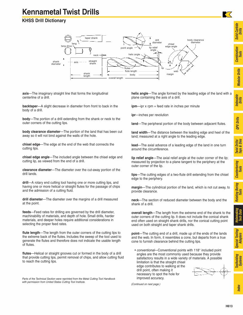
• split—Split points (commonlycalled Crankshaft points) wereoriginally developed for use ondrills designed for deep oilholes in automotive crankshafts.Since its inception, the split point has gained widespread use and is applied to both 118° and 135° includedpoint angles. Its main advantages are the ability to reduce thrustand eliminate walking at the drill point. This is a distinct advantage when the drill is used in a portable drill or in drillingapplications where bushings cannot be used. The split point alsohas two positive rake cutting edges extending to the center of thedrill, which can assist as a chipbreaker to produce small chips thatcan readily be ejected.
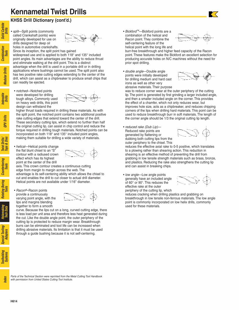
• notched—Notched pointswere developed for drillingtough alloys. Commonly usedon heavy web drills, this pointdesign can withstand thehigher thrust loads required in drilling these materials. As withthe split point, the notched point contains two additional positiverake cutting edges that extend toward the center of the drill.These secondary cutting lips, which extend no further than halfthe original cutting lip, can assist in chip control and reduce thetorque required in drilling tough materials. Notched points can beincorporated on both 118° and 135° included point angles, making them suitable for drilling a wide variety of materials.
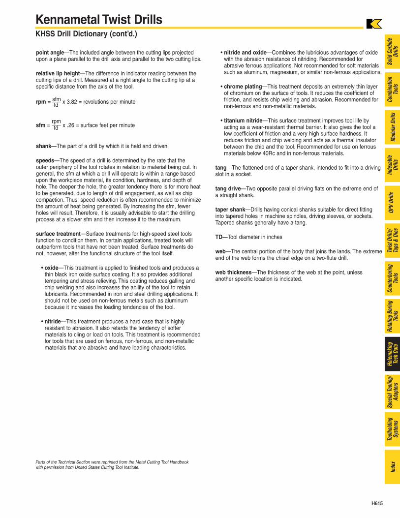
• helical—Helical points changethe flat blunt chisel to an “S”contour with a radiused crowneffect which has its highestpoint at the center of the drillaxis. This crown contour creates a continuous cutting edge from margin to margin across the web. The advantage is its self-centering ability which allows the chisel tocut and enables the drill to cut closer to actual drill diameter.Helical points are not available under 1/16" diameter.
• Racon®–Racon points provide a continuously varying point angle, with thelips and margins blendingtogether to form a smoothcurve. Because the lips cut on a long, curved cutting edge, thereis less load per unit area and therefore less heat generated duringthe cut. Like the double angle point, the outer periphery of thecutting lip is protected to reduce margin wear. Breakthroughburrs can be eliminated and tool life can be increased whendrilling abrasive materials. Its limitation is that it must be usedthrough a guide bushing because it is not self-centering.
• Bickford™—Bickford points are acombination of the helical andRacon point. They combine theself-centering feature of the helical point with the long life andburr-free breakthrough and higher feed capacity of the Raconpoint. These features make the Bickford an excellent selection forproducing accurate holes on N/C machines without the need forprior spot drilling.
• double angle—Double anglepoints were initially developed for drilling medium and hard castirons as well as other very abrasive materials. Their purposewas to reduce corner wear at the outer periphery of the cuttinglip. The point is generated by first grinding a larger included angle,and then a smaller included angle on the corner. This providesthe effect of a chamfer, which not only reduces wear, butimproves hole size, acts as a chipbreaker, and reduces chippingcorners of the lips when drilling hard materials. This point can beused to reduce breakthrough burr in soft materials. The length ofthe corner angle should be 1/3 the original cutting lip length.
• reduced rake (Dub Lip)—Reduced rake points are generated by flattening or dubbing both cutting lips from theouter periphery to the chisel. Thisreduces the effective axial rake to 0-5 positive, which translatesto a plowing rather than shearing action. This reduction in shearing is an effective method of preventing the drill from grabbing in low tensile strength materials such as brass, bronze,and plastics. Reducing the rake also strengthens the cutting lipand can assist in breaking chips.
• low angle—Low angle pointsgenerally have an included angleof 60° or 90°. This reduces theeffective rake at the outer periphery of the cutting lip, whichreduces cracking when drilling plastics and grabbing on breakthrough in low tensile non-ferrous materials. The low anglepoint is commonly incorporated on low helix drills, commonlyused for these materials.
Parts of the Technical Section were reprinted from the Metal Cutting Tool Handbookwith permission from United States Cutting Tool Institute.
H615
Solid
Car
bide
Drill
sCo
mbi
natio
nTo
ols
Mod
ular
Dril
lsIn
dexa
ble
Drill
sQP
VDr
ills
Twist
Dril
ls/Ta
ps &
Dies
Coun
terb
orin
gTo
ols
Rota
ting
Borin
gTo
ols
Hole
mak
ing
Tech
Dat
aSp
ecia
l Too
ling/
Adap
ters
Tool
hold
ing
Syste
ms
Inde
x
Kennametal Twist DrillsKHSS Drill Dictionary (cont’d.)
point angle—The included angle between the cutting lips projectedupon a plane parallel to the drill axis and parallel to the two cutting lips.
relative lip height—The difference in indicator reading between thecutting lips of a drill. Measured at a right angle to the cutting lip at aspecific distance from the axis of the tool.
rpm = sfm x 3.82 = revolutions per minutetd
sfm = rpm
x .26 = surface feet per minutetd
shank—The part of a drill by which it is held and driven.
speeds—The speed of a drill is determined by the rate that the outer periphery of the tool rotates in relation to material being cut. Ingeneral, the sfm at which a drill will operate is within a range basedupon the workpiece material, its condition, hardness, and depth ofhole. The deeper the hole, the greater tendency there is for more heatto be generated, due to length of drill engagement, as well as chipcompaction. Thus, speed reduction is often recommended to minimizethe amount of heat being generated. By increasing the sfm, fewerholes will result. Therefore, it is usually advisable to start the drillingprocess at a slower sfm and then increase it to the maximum.
surface treatment—Surface treatments for high-speed steel toolsfunction to condition them. In certain applications, treated tools willoutperform tools that have not been treated. Surface treatments donot, however, alter the functional structure of the tool itself.
• oxide—This treatment is applied to finished tools and produces athin black iron oxide surface coating. It also provides additionaltempering and stress relieving. This coating reduces galling andchip welding and also increases the ability of the tool to retainlubricants. Recommended in iron and steel drilling applications. Itshould not be used on non-ferrous metals such as aluminumbecause it increases the loading tendencies of the tool.
• nitride—This treatment produces a hard case that is highly resistant to abrasion. It also retards the tendency of softer materials to cling or load on tools. This treatment is recommendedfor tools that are used on ferrous, non-ferrous, and non-metallicmaterials that are abrasive and have loading characteristics.
• nitride and oxide—Combines the lubricious advantages of oxidewith the abrasion resistance of nitriding. Recommended for abrasive ferrous applications. Not recommended for soft materialssuch as aluminum, magnesium, or similar non-ferrous applications.
• chrome plating—This treatment deposits an extremely thin layerof chromium on the surface of tools. It reduces the coefficient offriction, and resists chip welding and abrasion. Recommended fornon-ferrous and non-metallic materials.
• titanium nitride—This surface treatment improves tool life by acting as a wear-resistant thermal barrier. It also gives the tool alow coefficient of friction and a very high surface hardness. Itreduces friction and chip welding and acts as a thermal insulatorbetween the chip and the tool. Recommended for use on ferrousmaterials below 40Rc and in non-ferrous materials.
tang—The flattened end of a taper shank, intended to fit into a drivingslot in a socket.
tang drive—Two opposite parallel driving flats on the extreme end ofa straight shank.
taper shank—Drills having conical shanks suitable for direct fittinginto tapered holes in machine spindles, driving sleeves, or sockets.Tapered shanks generally have a tang.
TD—Tool diameter in inches
web—The central portion of the body that joins the lands. The extremeend of the web forms the chisel edge on a two-flute drill.
web thickness—The thickness of the web at the point, unless another specific location is indicated.
Parts of the Technical Section were reprinted from the Metal Cutting Tool Handbookwith permission from United States Cutting Tool Institute.
H616
Solid
Car
bide
Drill
sCo
mbi
natio
nTo
ols
Mod
ular
Dril
lsIn
dexa
ble
Drill
sQP
VDr
ills
Twist
Dril
ls/Ta
ps &
Dies
Coun
terb
orin
gTo
ols
Rota
ting
Borin
gTo
ols
Hole
mak
ing
Tech
Dat
aSp
ecia
l Too
ling/
Adap
ters
Tool
hold
ing
Syste
ms
Inde
x
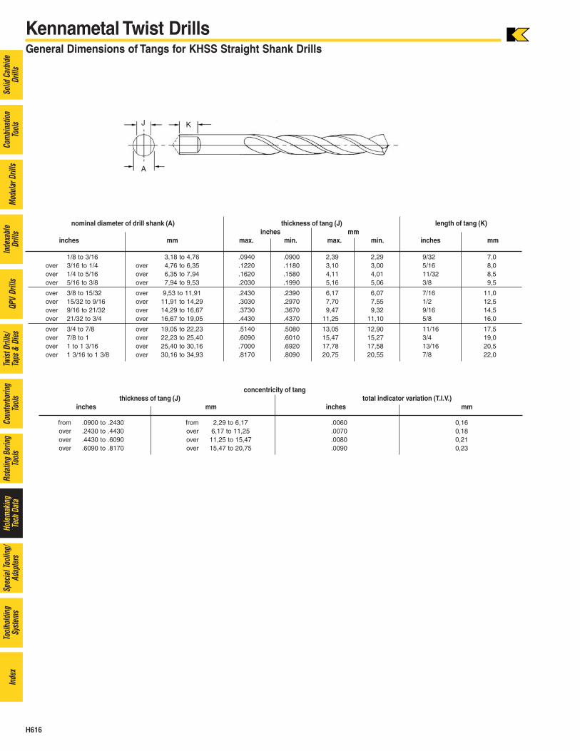
Kennametal Twist DrillsGeneral Dimensions of Tangs for KHSS Straight Shank Drills
1/8 to 3/16 3,18 to 4,76 .0940 .0900 2,39 2,29 9/32 7,0over 3/16 to 1/4 over 4,76 to 6,35 .1220 .1180 3,10 3,00 5/16 8,0over 1/4 to 5/16 over 6,35 to 7,94 .1620 .1580 4,11 4,01 11/32 8,5over 5/16 to 3/8 over 7,94 to 9,53 .2030 .1990 5,16 5,06 3/8 9,5
over 3/8 to 15/32 over 9,53 to 11,91 .2430 .2390 6,17 6,07 7/16 11,0over 15/32 to 9/16 over 11,91 to 14,29 .3030 .2970 7,70 7,55 1/2 12,5over 9/16 to 21/32 over 14,29 to 16,67 .3730 .3670 9,47 9,32 9/16 14,5over 21/32 to 3/4 over 16,67 to 19,05 .4430 .4370 11,25 11,10 5/8 16,0
over 3/4 to 7/8 over 19,05 to 22,23 .5140 .5080 13,05 12,90 11/16 17,5over 7/8 to 1 over 22,23 to 25,40 .6090 .6010 15,47 15,27 3/4 19,0over 1 to 1 3/16 over 25,40 to 30,16 .7000 .6920 17,78 17,58 13/16 20,5over 1 3/16 to 1 3/8 over 30,16 to 34,93 .8170 .8090 20,75 20,55 7/8 22,0
from .0900 to .2430 from 2,29 to 6,17 .0060 0,16over .2430 to .4430 over 6,17 to 11,25 .0070 0,18over .4430 to .6090 over 11,25 to 15,47 .0080 0,21over .6090 to .8170 over 15,47 to 20,75 .0090 0,23
nominal diameter of drill shank (A) thickness of tang (J) length of tang (K)inches mm
inches mm max. min. max. min. inches mm
concentricity of tangthickness of tang (J) total indicator variation (T.I.V.)
inches mm inches mm
H617
Solid
Car
bide
Drill
sCo
mbi
natio
nTo
ols
Mod
ular
Dril
lsIn
dexa
ble
Drill
sQP
VDr
ills
Twist
Dril
ls/Ta
ps &
Dies
Coun
terb
orin
gTo
ols
Rota
ting
Borin
gTo
ols
Hole
mak
ing
Tech
Dat
aSp
ecia
l Too
ling/
Adap
ters
Tool
hold
ing
Syste
ms
Inde
x
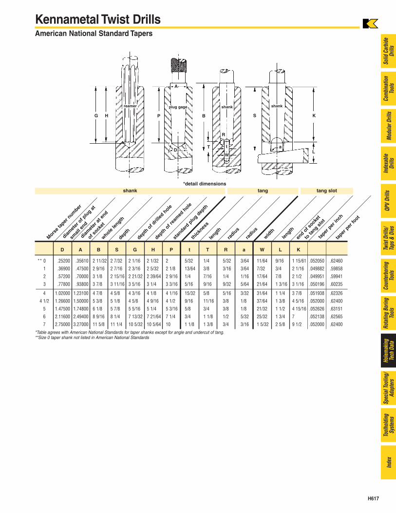
Kennametal Twist DrillsAmerican National Standard Tapers
** 0 .25200 .35610 2 11/32 2 7/32 2 1/16 2 1/32 2 5/32 1/4 5/32 3/64 11/64 9/16 1 15/61 .052050 .62460
1 .36900 .47500 2 9/16 2 7/16 2 3/16 2 5/32 2 1/8 13/64 3/8 3/16 3/64 7/32 3/4 2 1/16 .049882 .59858
2 .57200 .70000 3 1/8 2 15/16 2 21/32 2 39/64 2 9/16 1/4 7/16 1/4 1/16 17/64 7/8 2 1/2 .049951 .59941
3 .77800 .93800 3 7/8 3 11/16 3 5/16 3 1/4 3 3/16 5/16 9/16 9/32 5/64 21/64 1 3/16 3 1/16 .050196 .60235
4 1.02000 1.23100 4 7/8 4 5/8 4 3/16 4 1/8 4 1/16 15/32 5/8 5/16 3/32 31/64 1 1/4 3 7/8 .051938 .62326
4 1/2 1.26600 1.50000 5 3/8 5 1/8 4 5/8 4 9/16 4 1/2 9/16 11/16 3/8 1/8 37/64 1 3/8 4 5/16 .052000 .62400
5 1.47500 1.74800 6 1/8 5 7/8 5 5/16 5 1/4 5 3/16 5/8 3/4 3/8 1/8 21/32 1 1/2 4 15/16 .052626 .63151
6 2.11600 2.49400 8 9/16 8 1/4 7 13/32 7 21/64 7 1/4 3/4 1 1/8 1/2 5/32 25/32 1 3/4 7 .052138 .62565
7 2.75000 3.27000 11 5/8 11 1/4 10 5/32 10 5/64 10 1 1/8 1 3/8 3/4 3/16 1 5/32 2 5/8 9 1/2 .052000 .62400
*Table agrees with American National Standards for taper shanks except for angle and undercut of tang.**Size 0 taper shank not listed in American National Standards
G PH B
aL
R
T
W
KS
Dt
reamer plug gage
A
shank shank
Morse
taper
num
ber
D A B S G H P t T R a W L K
diamet
er o
f plu
g at
small
end
diamet
er a
t end
of sock
et
whole len
gth
depth
depth
of d
rilled
hole
depth
of r
eam
ed h
ole
stan
dard p
lug d
epth
thick
ness
length
radiu
s
radiu
s
width
length
end o
f sock
et
to ta
ng slo
t
taper
per
inch
taper
per
foot
shank tang tang slot*detail dimensions
H618
Solid
Car
bide
Drill
sCo
mbi
natio
nTo
ols
Mod
ular
Dril
lsIn
dexa
ble
Drill
sQP
VDr
ills
Twist
Dril
ls/Ta
ps &
Dies
Coun
terb
orin
gTo
ols
Rota
ting
Borin
gTo
ols
Hole
mak
ing
Tech
Dat
aSp
ecia
l Too
ling/
Adap
ters
Tool
hold
ing
Syste
ms
Inde
x
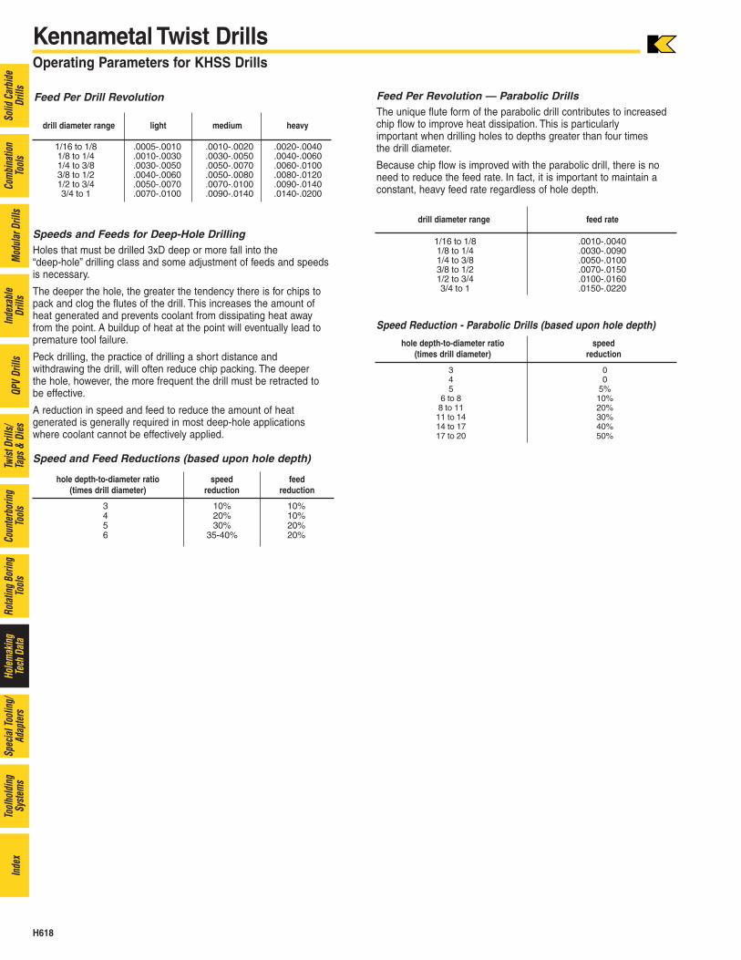
Speeds and Feeds for Deep-Hole DrillingHoles that must be drilled 3xD deep or more fall into the “deep-hole” drilling class and some adjustment of feeds and speedsis necessary.
The deeper the hole, the greater the tendency there is for chips topack and clog the flutes of the drill. This increases the amount ofheat generated and prevents coolant from dissipating heat awayfrom the point. A buildup of heat at the point will eventually lead topremature tool failure.
Peck drilling, the practice of drilling a short distance and withdrawing the drill, will often reduce chip packing. The deeper the hole, however, the more frequent the drill must be retracted tobe effective.
A reduction in speed and feed to reduce the amount of heat generated is generally required in most deep-hole applicationswhere coolant cannot be effectively applied.
Speed and Feed Reductions (based upon hole depth)
Kennametal Twist DrillsOperating Parameters for KHSS Drills
Feed Per Revolution — Parabolic DrillsThe unique flute form of the parabolic drill contributes to increasedchip flow to improve heat dissipation. This is particularly important when drilling holes to depths greater than four times the drill diameter.
Because chip flow is improved with the parabolic drill, there is noneed to reduce the feed rate. In fact, it is important to maintain aconstant, heavy feed rate regardless of hole depth.
Speed Reduction - Parabolic Drills (based upon hole depth)
drill diameter range light medium heavy
1/16 to 1/8 .0005-.0010 .0010-.0020 .0020-.00401/8 to 1/4 .0010-.0030 .0030-.0050 .0040-.00601/4 to 3/8 .0030-.0050 .0050-.0070 .0060-.01003/8 to 1/2 .0040-.0060 .0050-.0080 .0080-.01201/2 to 3/4 .0050-.0070 .0070-.0100 .0090-.01403/4 to 1 .0070-.0100 .0090-.0140 .0140-.0200
hole depth-to-diameter ratio speed feed(times drill diameter) reduction reduction
3 10% 10%4 20% 10%5 30% 20%6 35-40% 20%
drill diameter range feed rate
1/16 to 1/8 .0010-.00401/8 to 1/4 .0030-.00901/4 to 3/8 .0050-.01003/8 to 1/2 .0070-.01501/2 to 3/4 .0100-.01603/4 to 1 .0150-.0220
Feed Per Drill Revolution
hole depth-to-diameter ratio speed(times drill diameter) reduction
3 04 05 5%
6 to 8 10%8 to 11 20%11 to 14 30%14 to 17 40%17 to 20 50%
H619
Solid
Car
bide
Drill
sCo
mbi
natio
nTo
ols
Mod
ular
Dril
lsIn
dexa
ble
Drill
sQP
VDr
ills
Twist
Dril
ls/Ta
ps &
Dies
Coun
terb
orin
gTo
ols
Rota
ting
Borin
gTo
ols
Hole
mak
ing
Tech
Dat
aSp
ecia
l Too
ling/
Adap
ters
Tool
hold
ing
Syste
ms
Inde
x
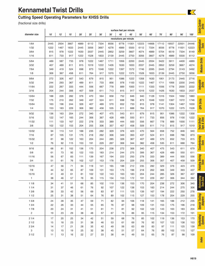
Kennametal Twist DrillsCutting Speed Operating Parameters for KHSS Drills(fractional size drills)
surface feet per minute
diameter size 10' 12' 15' 20' 25' 30' 35' 40' 45' 50' 60' 70' 80' 90' 100'
revolutions per minute
1/64 2445 2934 3667 4889 6112 7334 8556 9778 11001 12223 14668 17112 19557 22001 24446
1/32 1222 1467 1833 2445 3056 3667 4278 4889 5500 6112 7334 8556 9778 11001 12223
3/64 815 978 1222 1630 2037 2445 2852 3259 3667 4074 4889 5704 6519 7334 8149
1/16 611 733 917 1222 1528 1833 2139 2445 2750 3056 3667 4278 4889 5500 6112
5/64 489 587 733 978 1222 1467 1711 1956 2200 2445 2934 3422 3911 4400 4889
3/32 407 489 611 815 1019 1222 1426 1630 1833 2037 2445 2852 3259 3667 4074
7/64 349 419 524 698 873 1048 1222 1397 1572 1746 2095 2445 2794 3143 3492
1/8 306 367 458 611 764 917 1070 1222 1375 1528 1833 2139 2445 2750 3056
9/64 272 326 407 543 679 815 951 1086 1222 1358 1630 1901 2173 2445 2716
5/32 244 293 367 489 611 733 856 978 1100 1222 1467 1711 1956 2200 2445
11/64 222 267 333 444 556 667 778 889 1000 1111 1333 1556 1778 2000 2222
3/16 204 244 306 407 509 611 713 815 917 1019 1222 1426 1630 1833 2037
13/64 188 226 282 376 470 564 658 752 846 940 1128 1316 1504 1692 1880
7/32 175 210 262 349 437 524 611 698 786 873 1048 1222 1397 1572 1746
15/64 163 196 244 326 407 489 570 652 733 815 978 1141 1304 1467 1630
1/4 153 183 229 306 382 458 535 611 688 764 917 1070 1222 1375 1528
9/32 136 163 204 272 340 407 475 543 611 679 815 951 1086 1222 1358
5/16 122 147 183 244 306 367 428 489 550 611 733 856 978 1100 1222
11/32 111 133 167 222 278 333 389 444 500 556 667 778 889 1000 1111
3/8 102 122 153 204 255 306 357 407 458 509 611 713 815 917 1019
13/32 94 113 141 188 235 282 329 376 423 470 564 658 752 846 940
7/16 87 105 131 175 218 262 306 349 393 437 524 611 698 786 873
15/32 81 98 122 163 204 244 285 326 367 407 489 570 652 733 815
1/2 76 92 115 153 191 229 267 306 344 382 458 535 611 688 764
9/16 68 81 102 136 170 204 238 272 306 340 407 475 543 611 679
5/8 61 73 92 122 153 183 214 244 275 306 367 428 489 550 611
11/16 56 67 83 111 139 167 194 222 250 278 333 389 444 500 556
3/4 51 61 76 102 127 153 178 204 229 255 306 357 407 458 509
13/16 47 56 71 94 118 141 165 188 212 235 282 329 376 423 470
7/8 44 52 65 87 109 131 153 175 196 218 262 306 349 393 437
15/16 41 49 61 81 102 122 143 163 183 204 244 285 326 367 407
1 38 46 57 76 95 115 134 153 172 191 229 267 306 344 382
1 1/8 34 41 51 68 85 102 119 136 153 170 204 238 272 306 340
1 1/4 31 37 46 61 76 92 107 122 138 153 183 214 244 275 306
1 3/8 28 33 42 56 69 83 97 111 125 139 167 194 222 250 278
1 1/2 25 31 38 51 64 76 89 102 115 127 153 178 204 229 255
1 5/8 24 28 35 47 59 71 82 94 106 118 141 165 188 212 235
1 3/4 22 26 33 44 55 65 76 87 98 109 131 153 175 196 218
1 7/8 20 24 31 41 51 61 71 81 92 102 122 143 163 183 204
2 19 23 29 38 48 57 67 76 86 95 115 134 153 172 191
2 1/4 17 20 25 34 42 51 59 68 76 85 102 119 136 153 170
2 1/2 15 18 23 31 38 46 53 61 69 76 92 107 122 138 153
2 3/4 14 17 21 28 35 42 49 56 63 69 83 97 111 125 139
3 13 15 19 25 32 38 45 51 57 64 76 89 102 115 127
3 1/2 11 13 16 22 27 33 38 44 49 55 65 76 87 98 109
H620
Solid
Car
bide
Drill
sCo
mbi
natio
nTo
ols
Mod
ular
Dril
lsIn
dexa
ble
Drill
sQP
VDr
ills
Twist
Dril
ls/Ta
ps &
Dies
Coun
terb
orin
gTo
ols
Rota
ting
Borin
gTo
ols
Hole
mak
ing
Tech
Dat
aSp
ecia
l Too
ling/
Adap
ters
Tool
hold
ing
Syste
ms
Inde
x
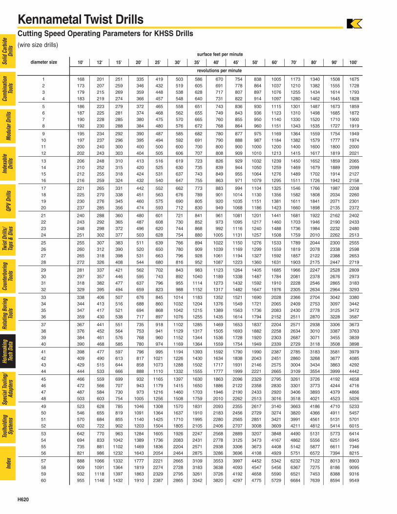
Kennametal Twist DrillsCutting Speed Operating Parameters for KHSS Drills(wire size drills)
1 168 201 251 335 419 503 586 670 754 838 1005 1173 1340 1508 16752 173 207 259 346 432 519 605 691 778 864 1037 1210 1382 1555 17283 179 215 269 359 448 538 628 717 807 897 1076 1255 1434 1614 17934 183 219 274 366 457 548 640 731 822 914 1097 1280 1462 1645 1828
5 186 223 279 372 465 558 651 743 836 930 1115 1301 1487 1673 18596 187 225 281 374 468 562 655 749 843 936 1123 1310 1498 1685 18727 190 228 285 380 475 570 665 760 855 950 1140 1330 1520 1710 19008 192 230 288 384 480 576 672 768 864 960 1151 1343 1535 1727 1919
9 195 234 292 390 487 585 682 780 877 975 1169 1364 1559 1754 194910 197 237 296 395 494 592 691 790 888 987 1184 1382 1579 1777 197411 200 240 300 400 500 600 700 800 900 1000 1200 1400 1600 1800 200012 202 243 303 404 505 606 707 808 909 1010 1213 1415 1617 1819 2021
13 206 248 310 413 516 619 723 826 929 1032 1239 1450 1652 1859 206514 210 252 315 420 525 630 735 839 944 1050 1259 1469 1679 1889 209915 212 255 318 424 531 637 743 849 955 1064 1276 1489 1702 1914 212716 216 259 324 432 540 647 755 863 971 1079 1295 1511 1726 1942 2158
17 221 265 331 442 552 662 773 883 994 1104 1325 1546 1766 1987 220818 225 270 338 451 563 676 789 901 1014 1130 1356 1582 1808 2034 226019 230 276 345 460 575 690 805 920 1035 1151 1381 1611 1841 2071 230120 237 285 356 474 593 712 830 949 1068 1186 1423 1660 1898 2135 2372
21 240 288 360 480 601 721 841 961 1081 1201 1441 1681 1922 2162 240222 243 292 365 487 608 730 852 973 1095 1217 1460 1703 1946 2190 243323 248 298 372 496 620 744 868 992 1116 1240 1488 1736 1984 2232 248024 251 302 377 503 628 754 880 1005 1131 1257 1508 1759 2010 2262 2513
25 255 307 383 511 639 766 894 1022 1150 1276 1533 1789 2044 2300 255526 260 312 390 520 650 780 909 1039 1169 1299 1559 1819 2078 2338 259827 265 318 398 531 663 796 928 1061 1194 1327 1592 1857 2122 2388 265328 272 326 408 544 680 816 952 1087 1223 1360 1631 1903 2175 2447 2719
29 281 337 421 562 702 843 983 1123 1264 1405 1685 1966 2247 2528 280930 297 357 446 595 743 892 1040 1189 1338 1487 1784 2081 2378 2676 297331 318 382 477 637 796 955 1114 1273 1432 1592 1910 2228 2546 2865 318332 329 395 494 659 823 988 1152 1317 1482 1647 1976 2305 2634 2964 3293
33 338 406 507 676 845 1014 1183 1352 1521 1690 2028 2366 2704 3042 338034 344 413 516 688 860 1032 1204 1376 1549 1721 2065 2409 2753 3097 344235 347 417 521 694 868 1042 1215 1389 1563 1736 2083 2430 2778 3125 347236 359 430 538 717 897 1076 1255 1435 1614 1794 2152 2511 2870 3228 3587
37 367 441 551 735 918 1102 1285 1469 1653 1837 2204 2571 2938 3306 367338 376 452 564 753 941 1129 1317 1505 1693 1882 2258 2634 3010 3387 376339 384 461 576 768 960 1152 1344 1536 1728 1920 2303 2687 3071 3455 383940 390 468 585 780 974 1169 1364 1559 1754 1949 2339 2729 3118 3508 3898
41 398 477 597 796 995 1194 1393 1592 1790 1990 2387 2785 3183 3581 397942 409 490 613 817 1021 1226 1430 1634 1838 2043 2451 2860 3268 3677 408543 429 515 644 858 1073 1288 1502 1717 1931 2146 2575 3004 3434 3863 429244 444 533 666 888 1110 1332 1555 1777 1999 2221 2665 3109 3554 3999 4442
45 466 559 699 932 1165 1397 1630 1863 2096 2329 2795 3261 3726 4192 465846 472 566 707 943 1179 1415 1650 1886 2122 2358 2830 3301 3773 4244 471647 487 584 730 973 1216 1460 1703 1946 2190 2433 2920 3406 3893 4379 486648 503 603 754 1005 1256 1508 1759 2010 2262 2513 3016 3518 4021 4523 5026
49 523 628 785 1046 1308 1570 1831 2093 2355 2617 3140 3663 4186 4710 523350 546 655 819 1091 1364 1637 1910 2183 2456 2729 3274 3820 4366 4911 545751 570 684 855 1140 1425 1710 1995 2280 2565 2851 3421 3991 4561 5131 570152 602 722 902 1203 1504 1805 2105 2406 2707 3008 3609 4211 4812 5414 6015
53 642 770 963 1284 1605 1926 2247 2568 2889 3207 3848 4490 5131 5773 641454 694 833 1042 1389 1736 2083 2431 2778 3125 3473 4167 4862 5556 6251 694555 735 881 1102 1469 1836 2204 2571 2938 3306 3673 4408 5142 5877 6611 734656 821 986 1232 1643 2054 2464 2875 3286 3696 4108 4929 5751 6572 7394 8215
57 888 1066 1332 1777 2221 2665 3109 3553 3997 4452 5342 6232 7122 8013 890358 909 1091 1364 1819 2274 2728 3183 3638 4093 4547 5456 6367 7275 8186 909559 932 1118 1397 1863 2329 2795 3261 3726 4192 4658 5590 6521 7453 8388 931660 955 1146 1432 1910 2387 2865 3342 3820 4297 4775 5729 6684 7639 8594 9549
surface feet per minute
diameter size 10' 12' 15' 20' 25' 30' 35' 40' 45' 50' 60' 70' 80' 90' 100'
revolutions per minute
H621
Solid
Car
bide
Drill
sCo
mbi
natio
nTo
ols
Mod
ular
Dril
lsIn
dexa
ble
Drill
sQP
VDr
ills
Twist
Dril
ls/Ta
ps &
Dies
Coun
terb
orin
gTo
ols
Rota
ting
Borin
gTo
ols
Hole
mak
ing
Tech
Dat
aSp
ecia
l Too
ling/
Adap
ters
Tool
hold
ing
Syste
ms
Inde
x
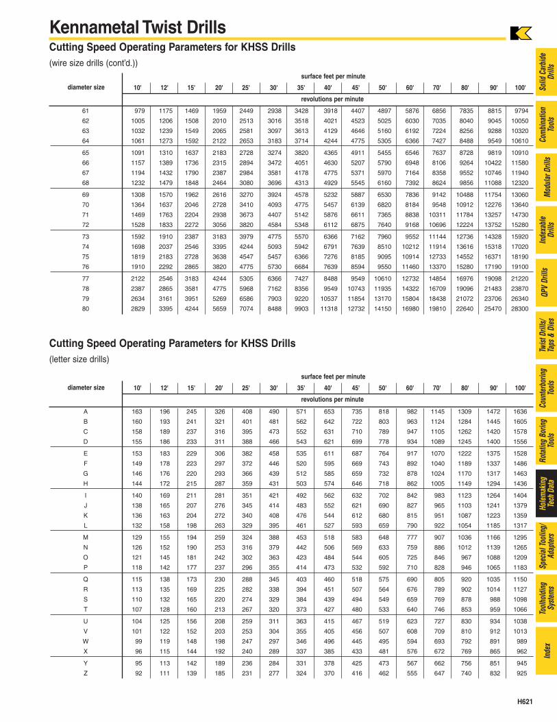
Kennametal Twist DrillsCutting Speed Operating Parameters for KHSS Drills(wire size drills (cont’d.))
Cutting Speed Operating Parameters for KHSS Drills(letter size drills)
61 979 1175 1469 1959 2449 2938 3428 3918 4407 4897 5876 6856 7835 8815 9794
62 1005 1206 1508 2010 2513 3016 3518 4021 4523 5025 6030 7035 8040 9045 10050
63 1032 1239 1549 2065 2581 3097 3613 4129 4646 5160 6192 7224 8256 9288 10320
64 1061 1273 1592 2122 2653 3183 3714 4244 4775 5305 6366 7427 8488 9549 10610
65 1091 1310 1637 2183 2728 3274 3820 4365 4911 5455 6546 7637 8728 9819 10910
66 1157 1389 1736 2315 2894 3472 4051 4630 5207 5790 6948 8106 9264 10422 11580
67 1194 1432 1790 2387 2984 3581 4178 4775 5371 5970 7164 8358 9552 10746 11940
68 1232 1479 1848 2464 3080 3696 4313 4929 5545 6160 7392 8624 9856 11088 12320
69 1308 1570 1962 2616 3270 3924 4578 5232 5887 6530 7836 9142 10488 11754 13060
70 1364 1637 2046 2728 3410 4093 4775 5457 6139 6820 8184 9548 10912 12276 13640
71 1469 1763 2204 2938 3673 4407 5142 5876 6611 7365 8838 10311 11784 13257 14730
72 1528 1833 2272 3056 3820 4584 5348 6112 6875 7640 9168 10696 12224 13752 15280
73 1592 1910 2387 3183 3979 4775 5570 6366 7162 7960 9552 11144 12736 14328 15920
74 1698 2037 2546 3395 4244 5093 5942 6791 7639 8510 10212 11914 13616 15318 17020
75 1819 2183 2728 3638 4547 5457 6366 7276 8185 9095 10914 12733 14552 16371 18190
76 1910 2292 2865 3820 4775 5730 6684 7639 8594 9550 11460 13370 15280 17190 19100
77 2122 2546 3183 4244 5305 6366 7427 8488 9549 10610 12732 14854 16976 19098 21220
78 2387 2865 3581 4775 5968 7162 8356 9549 10743 11935 14322 16709 19096 21483 23870
79 2634 3161 3951 5269 6586 7903 9220 10537 11854 13170 15804 18438 21072 23706 26340
80 2829 3395 4244 5659 7074 8488 9903 11318 12732 14150 16980 19810 22640 25470 28300
A 163 196 245 326 408 490 571 653 735 818 982 1145 1309 1472 1636
B 160 193 241 321 401 481 562 642 722 803 963 1124 1284 1445 1605
C 158 189 237 316 395 473 552 631 710 789 947 1105 1262 1420 1578
D 155 186 233 311 388 466 543 621 699 778 934 1089 1245 1400 1556
E 153 183 229 306 382 458 535 611 687 764 917 1070 1222 1375 1528
F 149 178 223 297 372 446 520 595 669 743 892 1040 1189 1337 1486
G 146 176 220 293 366 439 512 585 659 732 878 1024 1170 1317 1463
H 144 172 215 287 359 431 503 574 646 718 862 1005 1149 1294 1436
I 140 169 211 281 351 421 492 562 632 702 842 983 1123 1264 1404
J 138 165 207 276 345 414 483 552 621 690 827 965 1103 1241 1379
K 136 163 204 272 340 408 476 544 612 680 815 951 1087 1223 1359
L 132 158 198 263 329 395 461 527 593 659 790 922 1054 1185 1317
M 129 155 194 259 324 388 453 518 583 648 777 907 1036 1166 1295
N 126 152 190 253 316 379 442 506 569 633 759 886 1012 1139 1265
O 121 145 181 242 302 363 423 484 544 605 725 846 967 1088 1209
P 118 142 177 237 296 355 414 473 532 592 710 828 946 1065 1183
Q 115 138 173 230 288 345 403 460 518 575 690 805 920 1035 1150
R 113 135 169 225 282 338 394 451 507 564 676 789 902 1014 1127
S 110 132 165 220 274 329 384 439 494 549 659 769 878 988 1098
T 107 128 160 213 267 320 373 427 480 533 640 746 853 959 1066
U 104 125 156 208 259 311 363 415 467 519 623 727 830 934 1038
V 101 122 152 203 253 304 355 405 456 507 608 709 810 912 1013
W 99 119 148 198 247 297 346 496 445 495 594 693 792 891 989
X 96 115 144 192 240 289 337 385 433 481 576 672 769 865 962
Y 95 113 142 189 236 284 331 378 425 473 567 662 756 851 945
Z 92 111 139 185 231 277 324 370 416 462 555 647 740 832 925
surface feet per minute
diameter size 10' 12' 15' 20' 25' 30' 35' 40' 45' 50' 60' 70' 80' 90' 100'
revolutions per minute
surface feet per minute
diameter size 10' 12' 15' 20' 25' 30' 35' 40' 45' 50' 60' 70' 80' 90' 100'
revolutions per minute
H622
Solid
Car
bide
Drill
sCo
mbi
natio
nTo
ols
Mod
ular
Dril
lsIn
dexa
ble
Drill
sQP
VDr
ills
Twist
Dril
ls/Ta
ps &
Dies
Coun
terb
orin
gTo
ols
Rota
ting
Borin
gTo
ols
Hole
mak
ing
Tech
Dat
aSp
ecia
l Too
ling/
Adap
ters
Tool
hold
ing
Syste
ms
Inde
x
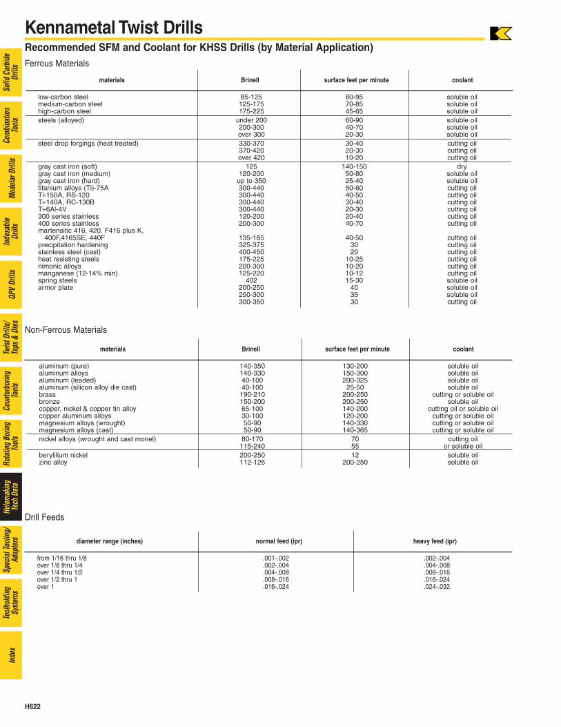
Kennametal Twist DrillsRecommended SFM and Coolant for KHSS Drills (by Material Application) Ferrous Materials
materials Brinell surface feet per minute coolant
low-carbon steel 85-125 80-95 soluble oilmedium-carbon steel 125-175 70-85 soluble oilhigh-carbon steel 175-225 45-65 soluble oilsteels (alloyed) under 200 60-90 soluble oil
200-300 40-70 soluble oilover 300 20-30 soluble oil
steel drop forgings (heat treated) 330-370 30-40 cutting oil370-420 20-30 cutting oilover 420 10-20 cutting oil
gray cast iron (soft) 125 140-150 drygray cast iron (medium) 120-200 50-80 soluble oilgray cast iron (hard) up to 350 25-40 soluble oiltitanium alloys (Ti)-75A 300-440 50-60 cutting oilTi-150A, RS-120 300-440 40-50 cutting oilTi-140A, RC-130B 300-440 30-40 cutting oilTi-6Al-4V 300-440 20-30 cutting oil300 series stainless 120-200 20-40 cutting oil400 series stainless 200-300 40-70 cutting oilmartensitic 416, 420, F416 plus K,
400F,4165SE, 440F 135-185 40-50 cutting oilprecipitation hardening 325-375 30 cutting oilstainless steel (cast) 400-450 20 cutting oilheat resisting steels 175-225 10-25 cutting oilnimonic alloys 200-300 10-20 cutting oilmanganese (12-14% min) 125-220 10-12 cutting oilspring steels 402 15-30 soluble oilarmor plate 200-250 40 soluble oil
250-300 35 soluble oil300-350 30 cutting oil
Drill Feeds
Non-Ferrous Materials
materials Brinell surface feet per minute coolant
aluminum (pure) 140-350 130-200 soluble oilaluminum alloys 140-330 150-300 soluble oilaluminum (leaded) 40-100 200-325 soluble oilaluminum (silicon alloy die cast) 40-100 25-50 soluble oilbrass 190-210 200-250 cutting or soluble oilbronze 150-200 200-250 soluble oilcopper, nickel & copper tin alloy 65-100 140-200 cutting oil or soluble oilcopper aluminum alloys 30-100 120-200 cutting or soluble oilmagnesium alloys (wrought) 50-90 140-330 cutting or soluble oil magnesium alloys (cast) 50-90 140-365 cutting or soluble oilnickel alloys (wrought and cast monel) 80-170 70 cutting oil
115-240 55 or soluble oilberylilium nickel 200-250 12 soluble oilzinc alloy 112-126 200-250 soluble oil
diameter range (inches) normal feed (ipr) heavy feed (ipr)
from 1/16 thru 1/8 .001-.002 .002-.004over 1/8 thru 1/4 .002-.004 .004-.008over 1/4 thru 1/2 .004-.008 .008-.016over 1/2 thru 1 .008-.016 .016-.024over 1 .016-.024 .024-.032
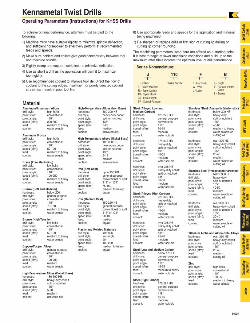
Kennametal Twist DrillsOperating Parameters (Instructions) for KHSS Drills
Series Nomenclature:
J 110 F B
J - Jobber Series Number F - Fractional B - BrightS - Screw Machine W - Wire X - Surface Treated,TL - Taper Length L - Letter Oxide
TS - Taper Shank Z - Bronze
EX - Extra LengthSP - Special Purpose
To achieve optimal performance, attention must be paid to the following:
1) Machine must have suitable rigidity to minimize spindle deflection,and sufficient horsepower to effectively perform at recommendedfeeds and speeds.
2) Make sure holders and collets give good concentricity between tooland machine spindle.
3) Rigidly clamp and support workpiece to minimize deflection.
4) Use as short a drill as the application will permit to maximize tool rigidity.
5) Use recommended coolant to improve tool life. Direct the flow ofcoolant to the cutting edges. Insufficient or poorly directed coolantstream can result in poor tool life.
6) Use appropriate feeds and speeds for the application and materialbeing machined.
7) Re-sharpen or replace drills at first sign of cutting lip dulling or cutting lip corner rounding.
The machining parameters listed here are offered as a starting point.It is best to begin at lower machining conditions and build up to themaximum after trials indicate the optimum level of drill performance.
Aluminum/Aluminum Alloysdrill style: high helixpoint style: conventionalpoint angle: 118°speed (sfm): 200-300feed: medium to heavycoolant: water soluble
Aluminum Bronzedrill style: high helixpoint style: conventionalpoint angle: 118°speed (sfm): 50-100feed: medium to heavycoolant: water soluble
Brass (Free Machining)drill style: low helix point style: conventionalpoint angle: 118°speed (sfm): 100-250feed: medium to heavycoolant: water soluble
Bronze (Soft and Medium)hardness: below 200drill style: general purposepoint style: conventionalpoint angle: 118°speed (sfm): 70-150feed: medium to heavycoolant: water soluble
Bronze (High Tensile)drill style: low helix point style: conventionalpoint angle: 118°speed (sfm): 50-100feed: medium to heavycoolant: water soluble
Copper/Copper Alloysdrill style: general purposepoint style: conventionalpoint angle: 118°speed (sfm): 100-200feed: mediumcoolant: water soluble
High-Temperature Alloys (Cobalt Base)hardness: 180-300 HBdrill style: heavy-duty cobaltpoint style: split or notchedpoint angle: 135°speed (sfm): 5-20feed: mediumcoolant: activated oils
High-Temperature Alloys (Iron Base)hardness: 180-300 HBdrill style: heavy-duty cobaltpoint style: split or notchedpoint angle: 135°speed (sfm): 5-20feed: mediumcoolant: activated oils
High-Temperature Alloys (Nickel Base)hardness: 180-300 HBdrill style: heavy-duty cobaltpoint style: split or notchedpoint angle: 135°speed (sfm): 5-15feed: mediumcoolant: activated oils
Iron (Soft Cast)hardness: up to 150 HBdrill style: general purposepoint style: conventional or splitpoint angle: 118° or 135°speed (sfm): 75-150feed: medium to heavycoolant: dry/air
Iron (Medium Cast)hardness: 150-250 HBdrill style: general purposepoint style: conventional or splitpoint angle: 118° or 135°speed (sfm): 50-100feed: mediumcoolant: dry/air
Plastic and Related Materialsdrill style: low helixpoint style: low anglepoint angle: 90°speed (sfm): 100-200feed: medium to heavy coolant: dry/air
Steel (Alloyed Low and Medium Carbon)hardness: 125-275 HBdrill style: general purposepoint style: conventionalpoint angle: 118°speed (sfm): 50-70feed: mediumcoolant: water soluble
hardness: 275-325 HBdrill style: heavy-dutypoint style: split or notchedpoint angle: 135°speed (sfm): 40-55feed: mediumcoolant: water soluble
hardness: over 325 HBdrill style: heavy-duty cobaltpoint style: split or notchedpoint angle: 135°speed (sfm): 30-50feed: mediumcoolant: water soluble
Steel (Alloyed High Carbon)hardness: 225-325 HBdrill style: heavy-dutypoint style: split or notchedpoint angle: 135°speed (sfm): 45-60feed: mediumcoolant: water soluble
hardness: over 325 HBdrill style: heavy-duty cobaltpoint style: split or notchedpoint angle: 135°speed (sfm): 25-40feed: mediumcoolant: water soluble
Steel (Low and Medium Carbon)hardness: below 175 HBdrill style: general purposepoint style: conventionalpoint angle: 118°speed (sfm): 45-95feed: medium to heavycoolant: water soluble
Steel (High Carbon)hardness: 175-225 HBdrill style: general purposepoint style: conventionalpoint angle: 118°speed (sfm): 45-65feed: mediumcoolant: water soluble
Stainless Steel (Austenitic/Martensitic)hardness: below 300 HBdrill style: heavy-dutypoint style: split or notchedpoint angle: 135°speed (sfm): 40-60feed: medium to heavycoolant: water soluble or
cutting oil
hardness: over 300 HBdrill style: heavy-duty cobaltpoint style: split or notchedpoint angle: 135°speed (sfm): 20-40feed: mediumcoolant: water soluble or
cutting oil
Stainless Steel (Precipitation Hardened)hardness: below 300 HBdrill style: heavy-dutypoint style: split or notchedpoint angle: 135°speed (sfm): 40-50feed: mediumcoolant: water soluble or
cutting oil
hardness: over 300 HBdrill style: heavy-duty cobaltpoint style: split or notchedpoint angle: 135°speed (sfm): 20-40feed: mediumcoolant: water soluble or
cutting oil
Titanium Alpha and Alpha-Beta Alloyshardness: over 250 HBdrill style: heavy-duty cobaltpoint style: split or notchedpoint angle: 135°speed (sfm): 20-45feed: mediumcoolant: cutting oil
Zincdrill style: high helixpoint style: conventionalpoint angle: 118°speed (sfm): 150-250feed: medium to heavycoolant: water soluble
Material
H623
Solid
Car
bide
Drill
sCo
mbi
natio
nTo
ols
Mod
ular
Dril
lsIn
dexa
ble
Drill
sQP
VDr
ills
Twist
Dril
ls/Ta
ps &
Dies
Coun
terb
orin
gTo
ols
Rota
ting
Borin
gTo
ols
Hole
mak
ing
Tech
Dat
aSp
ecia
l Too
ling/
Adap
ters
Tool
hold
ing
Syste
ms
Inde
x
H624
Solid
Car
bide
Drill
sCo
mbi
natio
nTo
ols
Mod
ular
Dril
lsIn
dexa
ble
Drill
sQP
VDr
ills
Twist
Dril
ls/Ta
ps &
Dies
Coun
terb
orin
gTo
ols
Rota
ting
Borin
gTo
ols
Hole
mak
ing
Tech
Dat
aSp
ecia
l Too
ling/
Adap
ters
Tool
hold
ing
Syste
ms
Inde
x
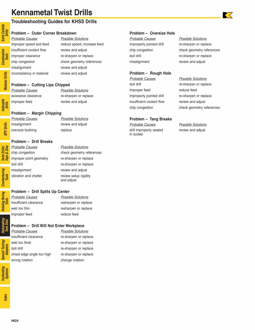
Kennametal Twist DrillsTroubleshooting Guides for KHSS Drills
Problem – Outer Corner BreakdownProbable Causes Possible Solutionsimproper speed and feed reduce speed, increase feed
insufficient coolant flow review and adjust
improper clearance re-sharpen or replace
chip congestion check geometry references
misalignment review and adjust
inconsistency in material review and adjust
Problem – Cutting Lips ChippedProbable Causes Possible Solutionsexcessive clearance re-sharpen or replace
improper feed review and adjust
Problem – Margin ChippingProbable Causes Possible Solutionsmisalignment review and adjust
oversize bushing replace
Problem – Drill BreaksProbable Causes Possible Solutionschip congestion check geometry references
improper point geometry re-sharpen or replace
dull drill re-sharpen or replace
misalignment review and adjust
vibration and chatter review setup rigidity and adjust
Problem – Drill Splits Up CenterProbable Causes Possible Solutionsinsufficient clearance resharpen or replace
web too thin resharpen or replace
improper feed reduce feed
Problem – Drill Will Not Enter WorkpieceProbable Causes Possible Solutionsinsufficient clearance re-sharpen or replace
web too thick re-sharpen or replace
dull drill re-sharpen or replace
chisel edge angle too high re-sharpen or replace
wrong rotation change rotation
Problem – Oversize HoleProbable Causes Possible Solutionsimproperly pointed drill re-sharpen or replace
chip congestion check geometry references
dull drill re-sharpen or replace
misalignment review and adjust
Problem – Rough HoleProbable Causes Possible Solutionsdull drill re-sharpen or replace
improper feed reduce feed
improperly pointed drill re-sharpen or replace
insufficient coolant flow review and adjust
chip congestion check geometry references
Problem – Tang BreaksProbable Causes Possible Solutionsdrill improperly seated review and adjustin socket