Kat-SV-2012-Intro-1111 Kat-SV-2007-Intro · + Solder contacts for manual soldering or dip soldered...
184
2012 Circular Connectors Setting Standards
Transcript of Kat-SV-2012-Intro-1111 Kat-SV-2007-Intro · + Solder contacts for manual soldering or dip soldered...

2012
Circular Connectors
Setting Standards

2
Setting Standards
HUMMEL AG

33
NEWS
hummel.com – your website!
Online Catalog
Searching Products
Technology Center
Download-Center
Enclosure-Configurator
News of the HUMMEL AG
Product Pictures and Product InformationProduct and Assembly VideosAssembly and Operations Manual Technical drawings3D dataCertificates
Part Number searchSearching Details
Technical Information (Protection, thread, material, …)Diagrams and evaluationProduct descriptionAssembly Video and Operations Manual
Catalog and FlyerAssembly instructions and installation instructionsPress releasesCertificates and approvals…
Individual EnclosuresEnclosure SolutionsOnline configuration, requesting and ordering
Trade fairs and exhibitionsPress releasesNew ProductsJob vacanciesStudies, training and vocational practical training
Touch Electronic Electro technologyHeating Valves andAccessories
Metal and plastic engineering
HUMMEL divisions

4
TWILOCK
+ Quick Connect with patented Polygon Lock
+ Easy handling
+ Exceptional functionality
+ Multi functional: Ideal with Twilock and screw connection
Clearly defined Positioning
Can be locked with a slight rotation from OPEN to CLOSE
Multi functional: Special thread allows use of Twilock and screw connection
Setting Standards

5
Connector4 small drivesConnector4 small drives
TWINTUS
Optional EMC-sheet for separatingsignal and power areas
Version M 16 / M 12 available
IP 67 (NEMA 4x) self sealing,even for threaded holes
Colour coded inserts (DESINA colour code)
The new Low-Cost-Standard for Drives
+ Minimized Size
+ Free choice of Signal and Power Inserts
+ Flange 20 x 20 and 25 x 25
Setting Standards

6
Setting Standards
Integrated shield springs for extremely easy shield connection
End-to-end shielding of data inserts prevents crosstalk
4 Twinax inserts and 12 additional contacts provide for maximum power density in M 23 housing
M 23 Fast Ethernet PoE
+ Data transfer up to Gigabit rate, Multibus II capability
+ Hybrid connectors for combined data and power transmission
+ Five separate shield potentials available
+ Rugged, safe, compact: ideal for use in rough industrial environments

7
M 23 RJ 45: Robust – simple & small!
Setting Standards
A standard RJ 45 connection is suitable as service and programm-able interface.
Integrated cable strain relief warrantan IP 67 / IP 69 K rating making theM 23 based RJ 45 Connector anideal solution for robust applications.
Integrated coupler accomodates off-the-shelf RJ 45 patch cables.
Design allows for terminated patchcable

8
SLS-Technology
The new, high performance type of contacts – HUMMEL SLS -Technology (Spring Loaded Socket)
+ Integrated spring mates with the pin contact and encompasses it radially
+ Exceptional electrical performance with ultimate contact reliability
+ Tinned solder contacts assure easy and quick assembly
The circular shaped outside configuration of the socket ensures a perfect concentric position duringconnection
Radially encompassing copperberyllium spring contacts assure lowplug-in resistance and high cycle life(mating cycles)
Reduced assembly time in solderingby a tinned surface
Lowest contact resistance as a resultof a gold plated contact area
Setting Standards

9
Setting Standards
User friendly assembly
Flexible EMC-O-ring guarantees reli-able EMC-protection for light andheavy braided shields.
Strain relief insert with four fingers,secured in a recess, prevents cablerotation.
Cable assembly and shielding ispossible in a single operation.
Colour coding of spacers for male and female inserts
+ Clear and modular structure of all connector series
+ Patented modular strain relief insert and contact insert
+ One step cable assembly and shielding
+ Simple, quick and reliable assembly into the connector housing

10
Setting Standards
Euro-Lock-System®
Complete assembly and disassemblywithout special tools
Simple contact unlocking and disassembly
Quick assembly
Secure contact lock
Euro-Lock-System® – the patented locking system
+ The integrated locking clip secures the contacts in the insert
+ Easy assembly and disassembly of the contacts
+ No special tools required

11
RoHS
File-No. E 213337
Setting Standards
Unique Benefits
MULTI Seal Connector
Fexible conduit connector
Strain Relief Fitting with flex protection for cable
+ Interchangeability of pin or socket inserts in every style connector housing
+ integrated Liquid Tight Strain Relief Fitting
+ Internationally certified exceptional quality

12
Setting Standards
Dip solder contacts for PC boards
Solder contacts
Machined crimp contacts
SUB-D contacts, stamped, tapemounted
+ Insert can be used for all types of contacts
+ Crimp contacts machined or on tape
+ Solder contacts for manual soldering or dip soldered for PC boards
The Insert – One for all
13
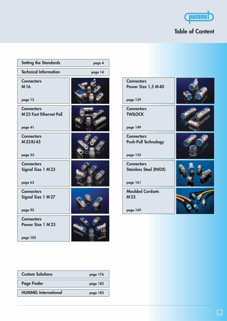
Table of Content
page 4Setting the Standards
Connectors M16
Connectors Power Size 1,5 M 40
Connectors M 23 RJ 45
Connectors TWILOCK
Connectors Signal Size 1 M 23
Connectors Push-Pull Technology
Connectors Signal Size 1 M 27
Connectors Stainless Steel (INOX)
Moulded CordsetsM 23
Connectors Power Size 1 M23
page 14
page 15
ConnectorsM 23 Fast Ethernet PoE
page 41
page 129
page 53
page 149
page 63
page 155
page 95
page 161
page 169
page 105
page 176
page 182
page 183HUMMEL International
Page Finder
Custom Solutions
Technical Information
14
!
Setting Standards
Technical Information
Nominal CurrrentAllowable current (Amp), that can be transmitted by each contact continuously and simultaneously.
Nominal VoltageAllowable voltage (Volt), that can be applied to each contact continuously and simultaneously.
Test VoltageVoltage which, under certain conditions, a connector can be exposed to without breakdown.
Degree of ProtectionPotential dirt accumulation of a disconnected connector in a certain environment.
Degree of Protection 2No permanent conductive dirt accumulation will occur. Temporary conductive dirt accumulation, such as condensation, is possible. Typical for households, offices, laboratories and test labs.
Degree of Protection 3Conductive, as well as dry non-conductive dirt accumulation can occur. It can be temporarily conductive due to condensation.Typical for industrial and factory environments.
Additional remarks (pollution level)If connectors being defined for pollution degree 1 and overvoltage category 1 are applied for other conditions (higher pollu-tion degree and higher overvoltage category) voltages level reduce correspondingly. But the connectors can be used withoutany problems at reduced maximum voltages.
Mating cyclesMating cycles are the number of insertion and extraction cycles a connector can withstand before the electrical or mechanicalfailure in relationship to the connector’s design specification.
Air gapThe minimum gap of air between two conducting surfaces permissible at given voltage.
Creep distanceThe minimum dimension along the surface of an insulating material between two conducting surfaces.
PEThe PE-Contact is a ground contact for security reasons.
- - - - - - - - - - - - - - - - - - - - - - - - - - - - - - - - - - - - - - - - - - - - - - - - - - - - - - - - - - - - - - - - - - - - - - - - - - - - - - - - - - - - - - - - - - - - - - - - - - - - - - - - - -Safety GuidelinesWhen HUMMEL connectors are used for voltages greater than 50 Volts with conductive shell components they must be used inaccordance with the safety regulations DIN VDE Part 410; IEC 60364-4-41. This regulation basically dictates that the powersource should be turned off before mating and unmating connector. This regulation does not provide protection against electri-cal shock when mating and unmating connectors in the field.- - - - - - - - - - - - - - - - - - - - - - - - - - - - - - - - - - - - - - - - - - - - - - - - - - - - - - - - - - - - - - - - - - - - - - - - - - - - - - - - - - - - - - - - - - - - - - - - - - - - - - - - - -
Don’t connect or disconnect HUMMEL Connectors under load.

15
incLusive
Setting Standards
Connectors M 16

16
1
2 3
1
23
1
6
2
3
4
5
1
2
3
4
56
Dimensions and specifications may be changed without prior notice
Accessories page 29
page 22Inserts
page 18Housings
Product Overview

17Dimensions and specifications may be changed without prior notice
Electrical Data
Housing Copper-Zinc alloy Die Casting
Housing surface Nickel platedother surface upon request
Inserts (for contacts) Thermoplastic Polyamid PA 6 (Nylon 6/6), PBT Fire protection class V-0
Contacts Brass Alloy
Contact surface at point of contact Nickel and gold plated (0,25μm Au)
Minimum mating cycles > 1000
Seals / O-Rings Buna-N standard, optional Viton® (Viton is a registered trademark of DuPont)
Temperature range -40° C – 125° C (-40 °F – 257 °F)
Type of contacts Crimp, dip-solder (PCB)
Protection IP 67 / IP 69 K per EN 60529 (connected), NEMA 4x
Cable diameter range 2 – 11 mm (.08 – .43“)
Materials and Technical DataMechanical Data
M 16 Control Signal Connectors
Technical Data
Number of positions
Number of contacts
Contact-Ø [mm]
AWG [mm2]
Nominal current 1) [A]
Nominal voltage 2) [V~] degree of protection 2 4)
Nominal voltage 2) [V~] degree of protection 3 4)
Test voltage (Breakdown voltage) 3) [V~]
Insulation resistance [MΩ]
Max. contact resistance [mΩ]
Number of positions
Number of contacts
Contact-Ø [mm]
AWG [mm2]
Nominal current 1) [A]
Nominal voltage 2) [V~] degree of protection 2 4)
Nominal voltage 2) [V~] degree of protection 3 4)
Test voltage (Breakdown voltage) 3) [V~]
Insulation resistance [MΩ]
Max. contact resistance [mΩ]
1), 2), 3), 4) See Technical Information page 14
3 (3 x 1 mm) 3 (3 x 2 mm) 4 + 3 + PE / 320 V 4 + 3 + PE / 630 V
3 3 4 4 4 4
1 2 0,8 1,6 0,8 1,25
0,14 – 1 0,5 – 2,5 0,08 – 0,34 0,34 – 1,5 0,08 – 0,34 0,34 – 1,5
8 20 5 16 5 16
630 630 320 630 300 800
400 400 160 320 300 630
2500 2500 1500 2500 1500 2500
> 1010 > 1010 > 1010 > 1010
3 3 3 3 3
10 12 + 3 18
10 12 3 18
1 0,8 1,25 0,8
0,14 – 0,75 0,08 – 0,34 0,5 – 1,5 0,08 – 0,34
8 3 10 3
230 60 160 60
160 24 60 24
1500 1500 2500 1500
> 106 > 1010 > 1010
3 3 3 3

18 18
46,2
Ø 1
9,7
18 18
47,8
M 1
6 x
0,75
15
45
34,5
Ø 19,7
17
39,6
Ø 19,7
18
45
18
2 – 7 mm (.08 – .28“).........7.820.300.0005 – 9 mm (.20 – .35“).........7.820.400.0008 – 11 mm (.31 – .43“).......7.820.5000.00
2 – 7 mm (.08 – .28“).........7.810.300.0005 – 9 mm (.20 – .35“).........7.810.400.0008 – 11 mm (.31 – .43“).......7.810.5000.00
Dimensions and specifications may be changed without prior notice
Contacts and inserts page 22 • Assembly instructions page 34 / 35
Contacts and inserts page 22 • Assembly instructions page 36
Contacts and inserts page 22 • Assembly instructions page 37
Connectors M 16 / Housing
Cable-Ø Part Number
Cable-Ø Part Number
Cable-Ø Part Number
Straight Connector, Male Thread
Right Angle Connector, Female Thread
Right Angle Connector with positioning
Contacts and inserts page 22 • Assembly instructions page 34 / 35
Cable-Ø Part NumberStraight Connector, Female Thread
2 – 7 mm (.08 – .28“).........7.830.300.0005 – 9 mm (.20 – .35“).........7.830.400.000
Assembly tool 7.010.900.125 is required
2 – 7 mm (.08 – .28“).........7.831.300.0005 – 9 mm (.20 – .35“).........7.831.400.0008 – 11 mm (.31 – .43“).......7.831.500.000

Ø 18,6 + 0,1
M 1
6 x
0,75
21
20,346,2
2215
19
M 1
6 x
0,75
153146
15 20
Ø 16,2 + 0,1
2015
M2,5
23,5
15M 16 x 0,75 20 19,8
25
Ø 2,7
Ø 2,7
Ø 15 + 0,1 Ø 20 + 0,1
M 16 x 0,75
Ø 15
26
20
Ø 15,2 + 0,1
2015
Ø 2,7
1412
Panel hole
Panel hole
Connectors M 16 / Housing
Contacts and inserts page 22 • Assembly instructions page 34 / 35
Cable-Ø Part Number
Cable-Ø Part Number
Contacts and inserts page 22 • Assembly instructions page 34 / 35
Contacts and inserts page 22 • Assembly instructions page 38
Type Part Number
Dimensions and specifications may be changed without prior notice
4 x holes Ø 2,7mm (.11“) ..7.840.000.000Flange 20 x 20mm
4 x holes Ø 2,7mm............7.840.100.000Flange 25 x 25mm
Panel Connector with built in Cable Strain Relief
Panel Connector with built in Cable Strain Relief
Panel Connector, Male Thread, Front Mounting
Contacts and inserts page 22 • Assembly instructions page 38
Type Part Number
Short version4 x holes Ø 2,7mm (.11“) ..7.840.200.000Flange 20 x 20mm
Panel Connector, Male Thread, Front Mounting
Rear mounting, single hole mounted2 – 7 mm (.08 – .28“).........7.852.300.0005 – 9 mm (.20 – .35“).........7.852.400.000
Including jam nut PG 11
Rear mounting, M2,5 x 4 single hole mounted2 – 7 mm (.08 – .28“).........7.847.300.0005 – 9 mm (.20 – .35“).........7.847.400.000
Panel holePanel hole
Panel hole
max.
10 mm
max.
6 mm
20
28,5
41,2
M 1
6 x
0,75
36,5
31,7
1520 19,8
25
Ø 20 + 0,1Ø 14 + 0,1
Ø 2,7
Ø 2,7
16,2 + 0,1
15,2
+0,
1
Ø 16,2 + 0,1
19316
25
M 16 x 1,5
M 16 x 0,75
M16 x 0,75
Ø 15
26
20
Ø 16,2 + 0,1
2015
M2,5
1115
Ø 18,6 + 0,1
M 16 x 0,75PG11
26 22,5 21
227,5
18,6+0,1
17,8
+0,
1
Panel hole
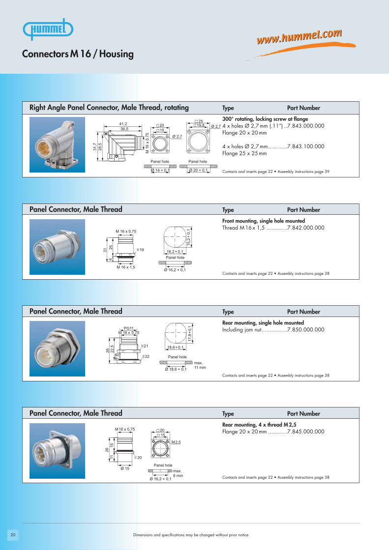
Front mounting, single hole mountedThread M16 x 1,5 .............7.842.000.000
300° rotating, locking screw at flange4 x holes Ø 2,7 mm (.11“) ..7.843.000.000Flange 20 x 20mm
4 x holes Ø 2,7mm............7.843.100.000Flange 25 x 25mm
Dimensions and specifications may be changed without prior notice
Contacts and inserts page 22 • Assembly instructions page 38
Type Part Number
Contacts and inserts page 22 • Assembly instructions page 38
Type Part Number
Contacts and inserts page 22 • Assembly instructions page 38
Connectors M 16 / Housing
Type Part Number Panel Connector, Male Thread
Contacts and inserts page 22 • Assembly instructions page 39
Type Part Number Right Angle Panel Connector, Male Thread, rotating
Rear mounting, single hole mountedIncluding jam nut................7.850.000.000
Rear mounting, 4 x thread M2,5Flange 20 x 20mm ............7.845.000.000
Panel Connector, Male Thread
Panel Connector, Male Thread
Panel hole
Panel hole
Panel hole Panel hole
max.
11 mm
max.
6 mm

21
Ø 1
5
20 15
18
4 x Ø 2,7 22
41 M 16 x 0,75
38,2
4 x Ø 2,7
18
22
41M 16 x 0,75
38,2
Ø 1
8,1
25 19,8
Ø 1
5 4 x Ø 2,7
41
22
20
M 12 x 1M 16 x 0,75
45,2
18
15
4 x Ø 2,7
Ø 1
8,1
25
18
41
22
M 12 x 1M 16 x 0,75
45,2
19,8
Connectors M 16 / Housing
Contacts and inserts page 22 • Assembly instructions page 33
Type Part Number
Type Part Number
Type Part Number
Type Part Number
Contacts and inserts page 22 • Assembly instructions page 33
Contacts and inserts page 22 • Assembly instructions page 33
Contacts and inserts page 22 • Assembly instructions page 33
Dimensions and specifications may be changed without prior notice
Flange 20 x 20mmUncoated ..........................7.848.000.000Surface nickel plated ..........7.848.000.001Surface black conductive.....7.848.000.00B
Flange 25 x 25mmUncoated ..........................7.848.100.000Surface nickel plated ..........7.848.100.001Surface black conductive.....7.848.100.00B
Flange 20 x 20mmUncoated ..........................7.848.200.000Surface nickel plated ..........7.848.200.001Surface black conductive.....7.848.200.00B
Flange 25 x 25mmUncoated ..........................7.848.300.000Surface nickel plated ..........7.848.300.001Surface black conductive.....7.848.300.00B
TWINTUS
TWINTUS
TWINTUS M 16 / M 12
TWINTUS M 16 / M 12

1
23
1
2 3
2,8
1,4
4,8
22
4,8
1,4
2,8
Dimensions and specifications may be changed without prior notice
Type Part Number Part Number
Pins SocketsInsert without contacts .......................7.003.983.101.................7.003.983.102
Insert with dip solder contactsLength 10 mm ..........................7.001.983.127.................7.001.983.108
Insert with dip solder contactsLength 17 mm ..........................7.001.983.137.................7.001.983.118
Contacts page 26 - 28
Insert socket mating view
Insert pin mating view
Inserts 3-pole (3 x 2 mm)
Contacts page 26 - 28
Insert socket mating view
Insert pin mating view
Type Part Number Part NumberInserts 3-pole (3 x 1 mm)Pins Sockets
Insert without contacts .......................7.003.903.101.................7.003.903.102
Insert with dip solder contactsLength 10 mm ..........................7.001.903.127.................7.001.903.108
Insert with dip solder contactsLength 17 mm ..........................7.001.903.137.................7.001.903.118
Connectors M 16 / Inserts / Pinouts
Required Contacts3 x 1 mm ................................7.010.901.001.................7.010.901.002/
7.010.901.012
Required Contacts3 x 2 mm ................................7.010.982.001.................7.010.982.002

23
4,53
7,6
4,53
7,6
4,53
7,6
4,53
7,6
Insert socket mating view
Insert pin mating view
Connectors M 16 / Inserts / Pinouts
Dimensions and specifications may be changed without prior notice
Inserts 4+3+PEType Part Number Part Number
Contacts page 26 - 28
Required Contacts4 x 0,8 mm .............................7.010.980.801.................7.010.980.802
4 x 1,6 mm .............................7.010.981.601.................7.010.981.602
Inserts 4+3+PE 630 VType Part Number Part Number
Pins SocketsInsert without contacts .......................7.003.943.101.................7.003.943.102
Insert RAL 2003 (DESINA orange)without contacts .......................7.053.943.101.................7.053.943.102
Insert with dip solder contactsLength 10 mm ..........................7.001.943.127.................7.001.943.108
Insert with dip solder contactsLength 17 mm ..........................7.001.943.137.................7.001.943.118
Insert socket mating view
Insert pin mating view
Contacts page 26 - 28
Required Contacts4 x 0,8 mm .............................7.010.980.811.................7.010.980.812
4 x 1,25 mm ...........................7.010.981.211.................7.010.981.212
Pins SocketsInsert without contacts .......................7.003.908.101.................7.003.908.102
Insert RAL 2003 (DESINA orange)without contacts .......................7.053.908.101.................7.053.908.102
Insert with dip solder contactsLength 10 mm 1) ........................7.001.908.127.................7.001.908.108
Insert with dip solder contactsLength 17 mm 1) ........................7.001.908.137.................7.001.908.118
1) Under development

72,9
7 2,9
1
2
3
4
56
1
6
2
3
4
5
Ø 7,5
6 x 60°
1
2
3
4
56
24
Insert socket mating view
Insert pin mating view
Type Part Number Part NumberInserts 6+PEPins Sockets
Insert without contacts .......................7.003.961.101.................7.003.961.102
Insert RAL 2003 (DESINA orange)without contacts .......................7.053.961.101.................7.053.961.102
Insert with dip solder contactsLength 10 mm ..........................7.001.961.127.................7.001.961.108
Insert with dip solder contactsLength 17 mm ..........................7.001.961.137.................7.001.961.118
Required Contacts7 x 1,25 mm ...........................7.010.981.211.................7.010.981.212
Pins SocketsInsert without contacts .......................7.003.910.101.................7.003.910.102
Insert RAL 6018 (DESINA green)without contacts .......................7.053.910.101.................7.053.910.102
Insert with dip solder contactsLength 10 mm ..........................7.001.910.127.................7.001.910.108
Insert with dip solder contactsLength 17 mm ..........................7.001.910.137.................7.001.910.118
Required Contacts10 x 1 mm ..............................7.010.981.001.................7.010.981.002
Contacts page 27 - 28
Connectors M 16 / Inserts / Pinouts
Contacts page 27 - 28
Insert socket mating view
Insert pin mating view
Type Part Number Part NumberInserts 10-pole
Dimensions and specifications may be changed without prior notice

Ø 9
Ø 3,6
12 x 30°3 x 120°
Ø 912 x 30°
2,174,87
3,91
0,561,56
2,25
25
Required Contacts12 x 0,8 mm ...........................7.010.980.801.................7.010.980.802
3 x 1,25 mm ...........................7.010.981.201.................7.010.981.202
Insert socket mating view
Insert pin mating view
Inserts 12+3-poleType Part Number Part Number
Contacts page 27 - 28
Pins SocketsInsert without contacts .......................7.003.985.101.................7.003.985.102
Insert with dip solder contactsLength 10 mm ..........................7.001.985.127.................7.001.985.108
Insert with dip solder contactsLength 17 mm ..........................7.001.985.137.................7.001.985.118
Required Contacts18 x 0,8 mm ...........................7.010.980.801.................7.010.980.802
Insert socket mating view
Insert pin mating view
Inserts 18-poleType Part Number Part Number
Contacts page 27 - 28
Pins SocketsInsert without contacts .......................7.003.988.101.................7.003.988.102
Insert RAL 6018 (DESINA green)without contacts .......................7.053.988.101.................7.053.988.102
Insert with dip solder contactsLength 10 mm ..........................7.001.988.127.................7.001.988.108
Insert with dip solder contactsLength 17 mm ..........................7.001.988.137.................7.001.988.118
Connectors M 16 / Inserts / Pinouts
Dimensions and specifications may be changed without prior notice

26
183
2
45 6
7
1211910
123
45
67
8
Connectors M 16 / Inserts / Pinouts
Dimensions and specifications may be changed without prior notice
Inserts M 12 for TWINTUS M 16 / M 12 8-pole
Inserts M 12 for TWINTUS M 16 / M 12 12-pole
Type Part Number
Type Part Number
PinsInsert with solder contacts .........A712-7001908103
PinsInsert with solder contacts .........A712-7001912103
insert pin mating view
insert pin mating view

27
Connectors M 16 / Contacts
Dimensions and specifications may be changed without prior notice
Type Crimp Range Part Number Contacts
Please see assembly instructions on page 40
Crimp socket 1 mm, machined................................0,08 – 0,56 mm2 (AWG 28 – 20)..7.010.901.012
Crimp socket 1 mm, machined................................0,34 – 1 mm2 (AWG 22 – 17) ......7.010.901.002
Crimp socket 0,8 mm, machined................................0,08 – 0,34 mm2 (AWG 28 – 22)..7.010.980.802
Crimp socket 1 mm, machined................................0,08 – 0,75 mm2 (AWG 28 – 18)..7.010.981.002
Crimp pin 1 mm, machined................................0,14 – 1 mm2 (AWG 26 – 17) .....7.010.901.001
Crimp pin 0,8 mm, machined................................0,08 – 0,34 mm2 (AWG 28 – 22)..7.010.980.811
Crimp socket 0,8 mm, machined................................0,08 – 0,34 mm2 (AWG 28 – 22)..7.010.980.812
Crimp pin 1 mm, machined................................0,08 – 0,75 mm2 (AWG 28 – 18)..7.010.981.001
Crimp pin 0,8 mm, machined................................0,08 – 0,34 mm2 (AWG 28 – 22)..7.010.980.801

28
Crimp pin 1,25 mm, machined................................0,5 – 1,5mm2 (AWG 20 – 16) .....7.010.981.201
Crimp pin 1,25 mm, machined................................0,5 – 1,5mm2 (AWG 20 – 16) .....7.010.981.211
Crimp socket 1,25 mm, machined................................0,5 – 1,5mm2 (AWG 20 – 16) .....7.010.981.202
Crimp socket 1,25 mm, machined................................0,5 – 1,5mm2 (AWG 20 – 16) .....7.010.981.212
Crimp socket 1,6 mm, machined................................0,34 – 1,5 mm2 (AWG 22 – 16)....7.010.981.602
Crimp pin 2 mm, machined................................1,0 – 2,5mm2 (AWG 17 – 14) .....7.010.982.001
Crimp socket 2 mm, machined................................1,0 – 2,5mm2 (AWG 17 – 14) ....7.010.982.002
Crimp pin 1,6 mm, machined................................0,34 – 1,5 mm2 (AWG 22 – 16) ..7.010.981.601
Crimp Tool Settings see page 31 / 32Please see assembly instructions on page 40
Type Crimp Range Part NumberContacts
Connectors M 16 / Contacts
Dimensions and specifications may be changed without prior notice

29
AccessoriesType Part Number
Connectors M 16 / Accessories
Dimensions and specifications may be changed without prior notice
Plastic protective capfor connectors with male thread .........................................7.000.980.161for connectors with female thread.......................................7.000.980.162
Brass protective cap for connectors with female thread.......................................7.010.900.163
Brass protective cap for connectors with male thread .........................................7.010.900.162
Brass protective cap with chain for connectors with female thread..............................................Length 70 mm ....................7.010.9S0.705
Brass protective cap with chain for connectors with male thread..............................................Length 70 mm ....................7.010.9S0.704
Assembly tool for Right Angle Connector M 16 ....................7.010.900.125

30
Plastic protective cap for TWINTUS
TWINTUS M 16 ...............................................................7.000.848.101TWINTUS M 16 / M 12 .....................................................7.000.848.102
Connectors M 16 / Accessories
Dimensions and specifications may be changed without prior notice
Please see assembly instructions on page 34
See page 84 for crimp tool instructions
Adaptor flange for Straight Connectors .....................................................7.010.900.135
Conduit adaptor DN 10 ..............................7.010.900.200Snapflex 16.......................7.010.900.201DN 12 ..............................7.010.900.202Snapflex 16.......................7.010.900.203
EMC-sheet
for TWINTUS Flange 20 x 20.............................................7.040.848.101for TWINTUS Flange 25 x 25.............................................7.040.848.102
Crimp tool for manual crimping of machined crimp contactsfor signal connectors M 16 and M 23 .................................7.000.900.904
Type Part NumberAccessories

31
Crimp Tool for Connectors M16
Dimensions and specifications may be changed without prior notice
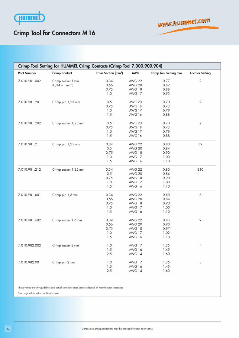
These values are only guidelines and actual conductor cross sections depend on manufacturer tolerances.
Crimp Tool Setting for HUMMEL Crimp Contacts (Crimp Tool 7.000.900.904)
See page 40 for crimp tool instructions
Part Number Crimp Contact Cross Section (mm2) AWG Crimp Tool Setting mm Locator Setting
7.010.980.801 Crimp pin 0,8 mm 0,08 AWG 28 0,57 100,14 AWG 26 0,600,25 AWG 24 0,640,34 AWG 22 0,73
7.010.980.802 Crimp socket 0,8 mm 0,08 AWG 28 0,57 100,14 AWG 26 0,600,25 AWG 24 0,640,34 AWG 22 0,73
7.010.980.811 Crimp pin 0,8 mm 0,08 AWG 28 0,57 B70,14 AWG 26 0,600,25 AWG 24 0,640,34 AWG 22 0,73
7.010.980.812 Crimp socket 0,8 mm 0,08 AWG 28 0,57 B80,14 AWG 26 0,600,25 AWG 24 0,640,34 AWG 22 0,73
7.010.981.001 Crimp pin1 mm 0,08 AWG 28 0,60 70,14 AWG 26 0,650,25 AWG 24 0,670,34 AWG 22 0,710,56 AWG 20 0,750,75 AWG 18 0,82
7.010.981.002 Crimp socket 1 mm 0,08 AWG 28 0,60 80,14 AWG 26 0,630,25 AWG 24 0,660,34 AWG 22 0,690,56 AWG 20 0,750,75 AWG 18 0,83
7.010.901.001 Crimp pin 1 mm 0,14 AWG 26 0,70 10,25 AWG 24 0,760,34 AWG 22 0,820,50 AWG 20 0,900,75 AWG 18 1,001,0 AWG 17 1,10
7.010.901.012 Crimp socket 1 mm 0,08 AWG 28 0,75 2(0,08-0,56 mm2) 0,14 AWG 26 0,78
0,25 AWG 24 0,820,34 AWG 22 0,860,56 AWG 20 0,90
32
These values are only guidelines and actual conductor cross sections depend on manufacturer tolerances.
Crimp Tool Setting for HUMMEL Crimp Contacts (Crimp Tool 7.000.900.904)
See page 40 for crimp tool instructions
Crimp Tool for Connectors M16
Part Number Crimp Contact Cross Section (mm2) AWG Crimp Tool Setting mm Locator Setting
7.010.901.002 Crimp socket 1 mm 0,34 AWG 22 0,77 2(0,34 – 1 mm2) 0,56 AWG 20 0,82
0,75 AWG 18 0,881,0 AWG 17 0,95
7.010.981.201 Crimp pin 1,25 mm 0,5 AWG 20 0,70 20,75 AWG 18 0,731,0 AWG 17 0,791,5 AWG 16 0,88
7.010.981.202 Crimp socket 1,25 mm 0,5 AWG 20 0,70 20,75 AWG 18 0,731,0 AWG 17 0,791,5 AWG 16 0,88
7.010.981.211 Crimp pin 1,25 mm 0,34 AWG 22 0,80 B90,5 AWG 20 0,840,75 AWG 18 0,901,0 AWG 17 1,001,5 AWG 16 1,10
7.010.981.212 Crimp socket 1,25 mm 0,34 AWG 22 0,80 B100,5 AWG 20 0,840,75 AWG 18 0,901,0 AWG 17 1,001,5 AWG 16 1,10
7.010.981.601 Crimp pin 1,6 mm 0,34 AWG 22 0,80 60,56 AWG 20 0,840,75 AWG 18 0,901,0 AWG 17 1,001,5 AWG 16 1,10
7.010.981.602 Crimp socket 1,6 mm 0,34 AWG 22 0,83 90,56 AWG 20 0,900,75 AWG 18 0,971,0 AWG 17 1,021,5 AWG 16 1,10
7.010.982.002 Crimp socket 2 mm 1,0 AWG 17 1,35 41,5 AWG 16 1,452,5 AWG 14 1,60
7.010.982.001 Crimp pin 2 mm 1,0 AWG 17 1,35 51,5 AWG 16 1,452,5 AWG 14 1,60
Dimensions and specifications may be changed without prior notice

33
1. 4.
5.
6.
7.
8.
9.
2.
3.
Dimensions and specifications may be changed without prior notice
Connectors M16/ Assembly Instructions
TWINTUS

34
1.
2.
3.
4.
6.
5.
Dimensions and specifications may be changed without prior notice
Connectors M16/ Assembly Instructions
Female Threaded Connector / Male Threaded Connector
20 mm
Crimp
15/18 15/18
click
4 mm

35
2.
3.
4.
6.
7.
8.
5.
1.
!
!
Dimensions and specifications may be changed without prior notice
Connectors M16/ Assembly Instructions
Female Threaded Connector / Male Threaded Connector 12 + 3
Pos. A, B, C
Pos. A, B, C
Crimp
max. 25 mm
4–5 mm
4 mm
15/1815/18
click
click
36
2.
3.
4.
5.
6.
7.
8.
9.
1.
Dimensions and specifications may be changed without prior notice
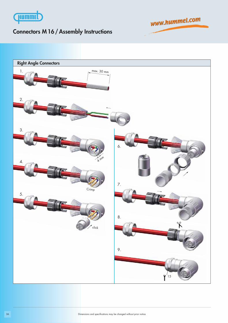
Right Angle Connectors
Connectors M16/Assembly Instructions
Crimp
click
4 mm
max. 30 mm
15

37
2.
3.
4.
5.
6.
7.
8.
1.
Dimensions and specifications may be changed without prior notice
Connectors M16/ Assembly Instructions
Right angle connector with positioning
Crimp
click
4 mm
max. 30 mm
15/18
17

38
1.
2.
3.
4.
Panel Connector
Connectors M16/Assembly Instructions
Dimensions and specifications may be changed without prior notice
Crimp
Code
click
click
4 mm

39
1.
2.
3.
4.
5.
6.
Right Angle Panel Connector
Dimensions and specifications may be changed without prior notice
Connectors M16/ Assembly Instructions
Crimp
1,5 mm
2 mm
click
4 m
m

40
!
Dimensions and specifications may be changed without prior notice
Crimping, Assembly and Disassembly of Contacts
Crimping, Assembly and Disassembly of ContactsCrimping- Remove conductor insulation 4 mm (.16“) max.- Select appropriate Crimp tool setting (see page 31 - 32)- Push crimp contact into opening of crimping tool- Insert stripped wire into the funnel shaped end of the crimp contact- Squeeze handles of crimping tool together connect contact to wire
Assembly- Remove crimped assembly and pull on wire to test connection- Push into desired position of insert
Disassembly of Contacts from InsertA small screwdriver is needed to remove the contacts from the insert.
- Release the white ring by a screwdriver out of the insert- Move the misplaced contacts out of the insert- Enter the ring back into the insert- Push the contacts back into insert
Shielding- Assemble strain relief insert with insert- Fold stranding of the shield back over the first O-Ring of the strain relief insert- Cut back the overextending braid
The stranding of the shield is not allowed to touch the second O-Ring. Otherwise the assembly may not be proof.

41
Setting Standards
M 23 Fast Ethernet PoE
42 Dimensions and specifications may be changed without prior notice
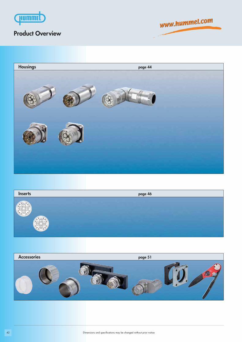
Accessories page 51
page 44Housings
Product Overview
page 46Inserts

43
Materials and Technical Data
Housing Copper-Zinc alloy Die Casting
Housing surface Nickel plated
Inserts (for contacts) PBT UL-94 V0, PA6
Contacts Brass Alloy
Contact surface at point of contact Nickel and gold plated (0,25μm Au)
Minimum mating cycles > 1000
Seals / O-Rings Perbunan NBR (Standard)
Temperature range -40° C – 125° C (-40 °F – 257 °F)
Type of contacts Crimp, dip-solder (PCB)
Protection IP 67 per EN 60529 (connected), NEMA 4x
Cable diameter range 11 – 17 mm (.43“ – .67“)
Dimensions and specifications may be changed without prior notice
M 23 Fast Ethernet PoE Connectors
Technical Data
Electrical Data
Mechanical Data
Number of positions
Number of contacts
Contact-Ø [mm]
AWG [mm2]
Nominal current 1) [A]
Nominal voltage 2) [V~] degree of protection 2 4)
Nominal voltage 2) [V~] degree of protection 3 4)
Test voltage (Breakdown voltage) 3) [V~]
Insulation resistance [MΩ]
Max. contact resistance [mΩ]
Impedance [Ω] (at 100MHz)
1), 2), 3), 4) See Technical Information page 14 *) for single contacts even 10 A possible
20 (4 x 2 + 12)
4 x 2 12
0,6 1
0,08 – 0,34 0,14 – 1 / 1,5
2 8*)
160 320
60 160
500 1500
> 106 > 106
3 3
100 –

Ø 2
7
76,3
24 2724
74,9
M 2
3 x
1
24 24
77,8
Ø 27
24
70,225
27
27
44
Ø 2,7
26,5
28,4
M 23 x 1
19,8
Ø 22
Ø 22,5 + 0,1
4 x holes Ø 2,7mm (.11“) ..7.408.000.000Flange 26 x 26 mm
Panel Connector, Male Thread, Front Mounting
Right Angle Connector, Female Thread , rotating
Straight Connector, Male Thread
Straight Female Connector
Panel hole
Dimensions and specifications may be changed without prior notice
Type Part Number
Cable-Ø Part Number
M 23 Fast Ethernet PoE Connectors / Housing
Cable-Ø Part Number
Inserts page 46 • Assembly instructions page 48
Inserts page 46 • Assembly instructions page 48
Inserts page 46 • Assembly instructions page 50
Inserts page 46 • Assembly instructions page 49
Cable-Ø Part Number
11-17 mm (.43 – .67“) ......7.108.600.000
11-17 mm (.43 – .67“) .......7.308.600.000
11-17 mm (.43 – .67“) .......7.208.600.000

45
Ø 23,
Ø 2,7
2627,7
M 23 x 1
20,5
Ø 23,1 + 0,1
4 x holes Ø 2,7mm (.11“) ..7.468.000.000Flange 26 x 26 mm
Panel Connector, Rear Mounting
Panel hole
Inserts page 46 • Assembly instructions page 49
M 23 Fast Ethernet PoE Connectors / Housing
Type Part Number
Dimensions and specifications may be changed without prior notice
max.
5 mm
46
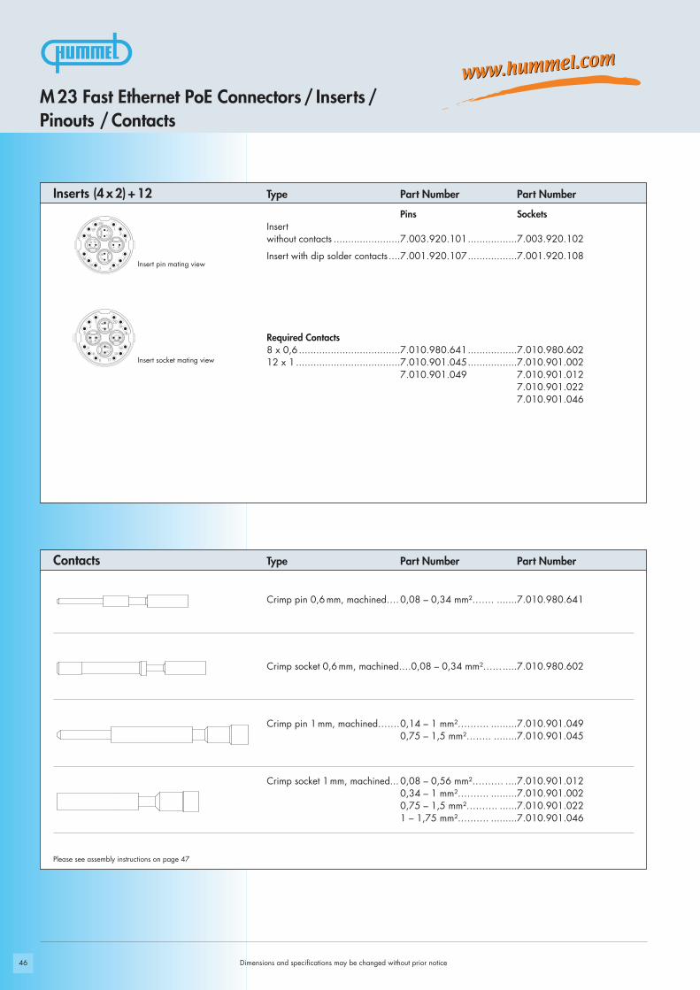
Insert socket mating view
Insert pin mating view
Required Contacts8 x 0,6 ...................................7.010.980.641.................7.010.980.60212 x 1 ....................................7.010.901.045.................7.010.901.002
7.010.901.049 7.010.901.0127.010.901.0227.010.901.046
Dimensions and specifications may be changed without prior notice
Please see assembly instructions on page 47
Type Part Number Part Number
Type Part Number Part Number
Inserts (4 x 2) + 12
Contacts
Pins SocketsInsert without contacts .......................7.003.920.101.................7.003.920.102
Insert with dip solder contacts ....7.001.920.107.................7.001.920.108
Crimp pin 0,6 mm, machined….0,08 – 0,34 mm²……. .......7.010.980.641
Crimp socket 0,6 mm, machined….0,08 – 0,34 mm²…….....7.010.980.602
Crimp pin 1 mm, machined…….0,14 – 1 mm²………. .........7.010.901.0490,75 – 1,5 mm²…….. ........7.010.901.045
Crimp socket 1 mm, machined... 0,08 – 0,56 mm²………. ....7.010.901.0120,34 – 1 mm²………. .........7.010.901.0020,75 – 1,5 mm²………. ......7.010.901.0221 – 1,75 mm²………. .........7.010.901.046
M 23 Fast Ethernet PoE Connectors / Inserts /Pinouts / Contacts

47
Part Number Crimp Contact Cross Section (mm2) AWG Crimp Tool Setting mm Locator Setting
7.010.980.641 Crimp pin 0,6 mm 0,08 AWG 28 0,57 B 1(0,08 – 0,34 mm²) 0,14 AWG 26 0,60
0,25 AWG 24 0,640,34 AWG 22 0,73
7.010.980.602 Crimp socket 0,6 mm 0,08 AWG 28 0,57 B 2(0,08 – 0,34 mm²) 0,14 AWG 26 0,60
0,25 AWG 24 0,640,34 AWG 22 0,73
7.010.901.049 Crimp pin 1 mm 0,14 AWG 26 0,70 B 3(0,14 – 1,0 mm²) 0,25 AWG 24 0,76
0,34 AWG 22 0,820,56 AWG 20 0,900,75 AWG 18 1,001,00 AWG 17 1,10
7.010.901.045 Crimp pin 1 mm 0,75 AWG 18 0,80 B 5(0,75 – 1,5 mm²) 1,00 AWG 17 0,85
1,50 AWG 16 0,95
7.010.901.012 Crimp socket 1 mm 0,08 AWG 28 0,75 B 4(0,08 – 0,56 mm²) 0,14 AWG 26 0,78
0,25 AWG 24 0,820,34 AWG 22 0,880,56 AWG 20 0,90
7.010.901.002 Crimp socket 1 mm 0,34 AWG 22 0,77 B 4(0,34– 1,0 mm²) 0,56 AWG 20 0,82
0,75 AWG 18 0,881,00 AWG 17 0,95
7.010.901.022 Crimp socket 1 mm 0,75 AWG 18 0,80 B 4(0,75 – 1,5 mm²) 1,00 AWG 17 0,86
1,50 AWG 16 0,95
7.010.901.046 Crimp socket 1 mm 1,00 AWG 17 0,85 B 6(1 – 1,75 mm²) 1,50 AWG 16 0,95
1,75 AWG 15 1,00
Crimp Tool Settings for HUMMEL Crimp Contacts (Crimp Tool 7.000.900.907)
Crimp Tool Settings for crimp contacts M 23 Fast Ethernet PoE
Dimensions and specifications may be changed without prior notice
These values are only guidelines and actual conductor cross sections depend on manufacturer tolerances.

48
click
7 8
13 1
4
9 10
12 17
12 17
9 10
13 1
4
7 8
1.
2.
3.
4.
5.
6.
7.
8.
9.
10.
11.
12.
13.
14.
15.
16.
!
x
y
z
Pins = 41mmSockets = 37mm
Pins = 7mmSockets = 0mm
Pins = 10mmSockets = 7mm
Straight Connector Male / Female Thread
Dimensions and specifications may be changed without prior notice
M 23 Fast Ethernet PoE Connectors / Assembly Instructions
Crimp
Crimp
Crimp
7.000.900.906
2724
click
click
click
click
Code
Code
Code
Code
Code
Position
+ Position17 mm
x
z
max. 4,5 mm
max. 4 mm

49
click
7 8
13 1
4
9 10
12 17
12 17
9 10
13 1
4
7 8
1.
2.
3.
4.
5.
8.
9.
10.
11.
12.
6.
7.
! x Pins = 10mmSockets = 7mm
Panel Connector
Dimensions and specifications may be changed without prior notice
M 23 Fast Ethernet PoE Connectors / Assembly Instructions
Crimp
Crimp
Crimp
7.000.900.906
click
click
clickclick
Code
Code
Code
Code
Position
Code+ Position
max. 4 mm
max. 4,5 mm
x

50
7 8
13 1
4
9 10
12 17
12 17
9 10
13 1
4
7 8
1.
2.
3.
4.
5.
6.
7.
8.
9.
10.
11.
12.
13.
14.
15.
16.
17.
!
x
y
Pins = 7mmSockets = 0mm
Pins = 10mmSockets = 7mm
Right Angle Connector
M 23 Fast Ethernet PoE Connectors / Assembly Instructions
Dimensions and specifications may be changed without prior notice
Code
Position
Code+ Position
Crimp
Crimp
Code
Code
Code
Code
7.000.900.906 27
27
24
click
click
click
80 mm55 mm
max. 4,5 mm
xy
max. 4 mm
51
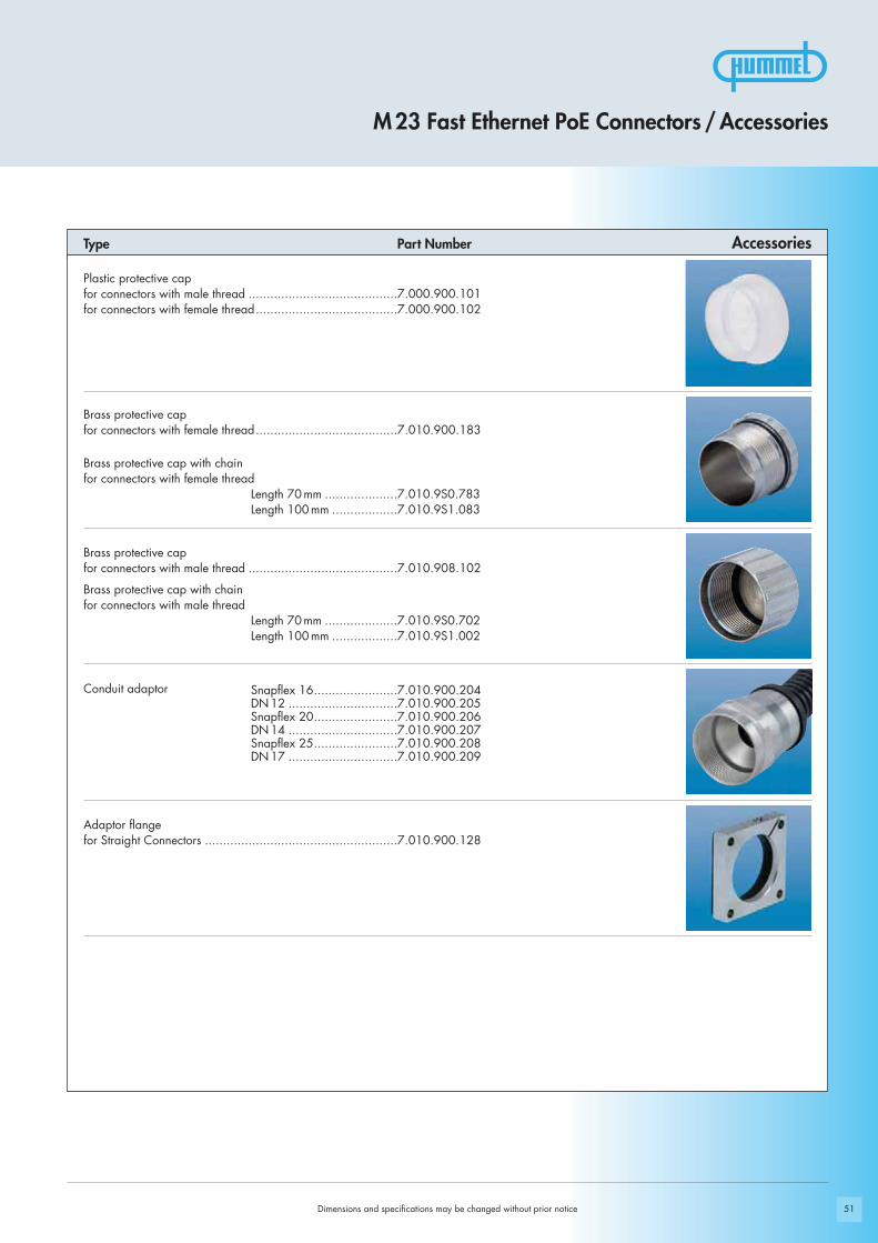
Plastic protective capfor connectors with male thread .........................................7.000.900.101for connectors with female thread.......................................7.000.900.102
Brass protective cap for connectors with female thread.......................................7.010.900.183
Brass protective cap with chain for connectors with female thread
Length 70 mm ....................7.010.9S0.783Length 100 mm ..................7.010.9S1.083
Brass protective cap for connectors with male thread .........................................7.010.908.102
Brass protective cap with chain for connectors with male thread
Length 70 mm ....................7.010.9S0.702Length 100 mm ..................7.010.9S1.002
Conduit adaptor
Adaptor flange for Straight Connectors .....................................................7.010.900.128
Dimensions and specifications may be changed without prior notice
M 23 Fast Ethernet PoE Connectors / Accessories
Type Part Number Accessories
Snapflex 16.......................7.010.900.204DN 12 ..............................7.010.900.205Snapflex 20.......................7.010.900.206DN 14 ..............................7.010.900.207Snapflex 25.......................7.010.900.208DN 17 ..............................7.010.900.209

52
Adapter flangefor moulded connectors .....................................................7.010.900.139
Multi-Bus adapter wired through I:I (excentric)
Multi-Bus I, Female Thread, Sockets 17poleMulti-Bus II, Male Thread, Pins …. ......................................7.010.900.143
Multi-Bus I, Female Thread, Pins, 17poleMulti-Bus II, Male Thread, Sockets …. .................................7.010.900.144
Control Cabinet adapter for Multibus II - AIDA
Rear Mounting, central locking...........................................7.010.900.145
I / O adapter module to scan or feed signals
Rear Mounting, central locking...........................................7.010.900.146
Manual Crimp tool for EMC sleeves M 23 Fast Ethernet PoE ..7.000.900.906
Manual Crimp tool for turned contactsM 23 Fast Ethernet PoE......................................................7.000.900.907
Type Part Number
Dimensions and specifications may be changed without prior notice
Accessories
M 23 Fast Ethernet PoE Connectors / Accessories
53
Setting Standards
Connectors M 23 RJ 45

54 Dimensions and specifications may be changed without prior notice
Accessories page 59
page 56Housings
Product Overview

55
Technical Data Materials and Technical DataHousing Brass Alloy, Die Cast
Housing Surface Nickel Plated
Inserts (for contacts) PBT UL-94 V0, PA 6
Contacts Brass Alloy
Contact Surface at point of contact Depends on RJ 45 type used
Seals / O-Rings NBR / FKM (Viton)
Temperature Range Depends on RJ 45 type used
Degree of Protection IP 67 / IP 69 K per EN 60529 (mated)
Cable diameter range 3 - 7 / 7 - 12 / 11 - 17mm
Number of Positions 4 / 6 / 8 poles, optional 4 + 2 / 6 + 2 / 8 + 2
Nominal Current 1) [A] Depends on RJ 45 type used
Nominal Voltage 2) [V~] Depends on RJ 45 type used
Test Voltage [V~] Depends on RJ 45 type used
Insulation Resistance [MΩ] Depends on RJ 45 type used
Max. Crossover Resistance [mΩ] Depends on RJ 45 type used
Max. Data Rate Depends on RJ 45 type used
1), 2) See Technical Information page 14
Dimensions and specifications may be changed without prior notice
M 23 RJ 45 Control Signal Connectors
Technical Data
69,5
24 24
Ø 2
6,2
79
M 2
3 x
1
2424
19
M 23 x 1Ø 2,7
25 19,8
Ø 23 + 0,1
56
M 23 x 1
Ø 2,7
34,5
25 19,8
Ø 20 + 0,1
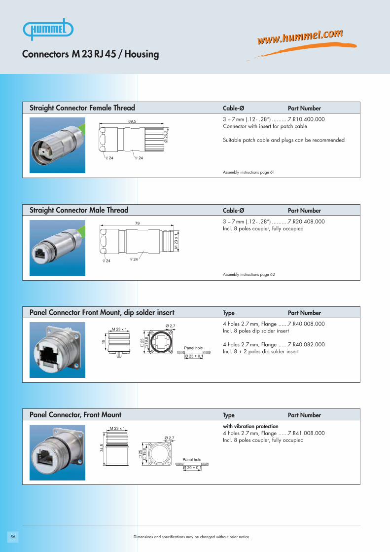
Panel Connector, Front Mount
Panel Connector Front Mount, dip solder insert
Straight Connector Male Thread
Straight Connector Female Thread3 – 7 mm (.12 - .28”) ..........7.R10.400.000Connector with insert for patch cable
Suitable patch cable and plugs can be recommended
with vibration protection4 holes 2.7 mm, Flange ......7.R41.008.000Incl. 8 poles coupler, fully occupied
4 holes 2.7 mm, Flange ......7.R40.008.000Incl. 8 poles dip solder insert
4 holes 2.7 mm, Flange ......7.R40.082.000Incl. 8 + 2 poles dip solder insert
3 – 7 mm (.12 - .28”) ..........7.R20.408.000Incl. 8 poles coupler, fully occupied
Panel hole
Panel hole
Dimensions and specifications may be changed without prior notice
Type Part Number
Type Part Number
Connectors M 23 RJ 45 / Housing
Cable-Ø Part Number
Assembly instructions page 61
Assembly instructions page 62
Cable-Ø Part Number

30 29
34,532
25 + 0,1
24,1
+ 0
,1
M 2
5 x
1,5
M 2
3 x
1
Ø 25 + 0,1
42376
24
20,2 + 0,1
19,1
+ 0
,1
M 2
3 x
1
M 2
0 x
1,5
Ø 20,2 + 0,1
57
62
41,1
35,5
60
M 2
3 x
1
Ø 2,7
25 19,8
Ø 20 + 0,1
M 23 x 1
Ø 23 + 0,1
2521 19 20,5
M 3
Single Hole Panel Connector
Single Hole Panel Connector
Right Angle Panel Connector, Male Thread
Panel Connector Rear Mount, dip solder insert
Rear MountM 25 x 1,5 thread ............7.R50.008.000Incl. 8 poles coupler, fully occupied
M 25 x 1,5 Locking Nut included
300 ° rotating, locking screw at flange4 holes 2.7 mm, Flange ......7.R43.008.000Incl. 8 poles coupler, fully occupied
Optional: Gasket
Simple installation with M 2.5 screws
with vibration protection4x M 3 thread, Flange .......7.R45.008.000Incl. 8 poles dip solder insert
4x M 3 thread, Flange .......7.R45.082.000Incl. 8 + 2 poles dip solder insert
Front Mount M 20 x1,5 thread...............7.R42.008.000Incl. 8 poles coupler, fully occupied
Optional:Gasket M 20 x 1,5, Locking Nut
Panel hole
Panel hole
Panel hole
Panel hole
Connectors M 23 RJ 45 / Housing
Type Part Number
Type Part Number
Type Part Number
Type Part Number
Dimensions and specifications may be changed without prior notice
max. 14 mm
max.
2 mm
24 30
42 3274
29
M 2
5 x
1,5
M 2
3 x
1Ø 25 + 0,1
Ø 23 + 0,1
70,545,5 25
24
M 2
3 x
1
20,525
M 2,5
58
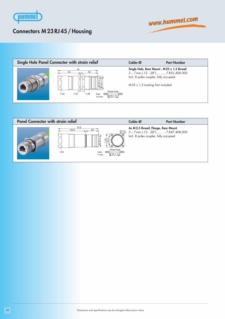
Panel Connector with strain relief
Single Hole Panel Connector with strain reliefSingle Hole, Rear Mount , M 25 x 1,5 thread3 – 7 mm (.12 - .28”) ..........7.R52.408.000Incl. 8 poles coupler, fully occupied
M 25 x 1,5 Locking Nut included
4x M 2,5 thread, Flange, Rear Mount3 – 7 mm (.12 - .28”) ..........7.R47.408.000Incl. 8 poles coupler, fully occupied
Dimensions and specifications may be changed without prior notice
Connectors M 23 RJ 45 / Housing
Cable–Ø Part Number
Cable–Ø Part Number
Panel hole
Panel hole
max.
14 mm
max.
7 mm

59
Plastic protective capfor connectors with male thread .........................................7.000.900.101for connectors with female thread.......................................7.000.900.102
Brass protective cap for connectors with female thread.......................................7.010.900.183
Brass protective cap for connectors with male thread .........................................7.010.900.102
Brass protective cap with chain for connectors with female thread..............................................Length 70 mm ....................7.010.9S0.783..............................................Length 100 mm ..................7.010.9S1.083
Brass protective cap with chain for connectors with male thread..............................................Length 70 mm ....................7.010.9S0.702..............................................Length 100 mm ..................7.010.9S1.002
Adapter flange for straight connectors ................................7.010.900.128
Dimensions and specifications may be changed without prior notice
Connectors M 23 RJ 45 / Accessories
Type Part Number Accessories
60
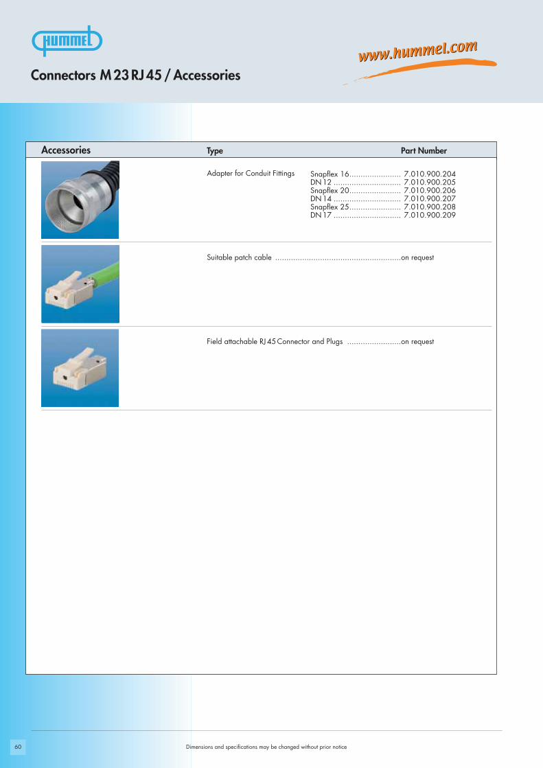
Snapflex 16....................... 7.010.900.204DN 12 .............................. 7.010.900.205Snapflex 20....................... 7.010.900.206DN 14 .............................. 7.010.900.207Snapflex 25....................... 7.010.900.208DN 17 .............................. 7.010.900.209
Adapter for Conduit Fittings
Suitable patch cable ........................................................on request
Field attachable RJ 45 Connector and Plugs ........................on request
Dimensions and specifications may be changed without prior notice
Connectors M 23 RJ 45/Accessories
Accessories Type Part Number

61
1.
2.
3.
4.
6.
5.
Connectors M 23 RJ 45/Assembly Instructions
Straight Connector, Female Thread
Dimensions and specifications may be changed without prior notice
27 24
Code
click

62
1.
2.
3.
4.
5.
27 24
click
Dimensions and specifications may be changed without prior notice
Connectors M 23 RJ 45/Assembly Instructions
Male Threaded Connector

63
Setting Standards
Signal Connectors M 23

64 Dimensions and specifications may be changed without prior notice
Accessories page 82
page 74Inserts
page 66Housings
Product Overview

65Dimensions and specifications may be changed without prior notice
Electrical Data
Housing Copper-Zinc alloy Die Casting
Housing surface Nickel platedother surface upon request
Inserts (for contacts) Thermoplastic Polyamid PA 6 (Nylon 6/6), PBT Fire protection class V-0
Contacts Brass Alloy
Contact surface at point of contact Nickel and gold plated (0,25μm Au)
Minimum mating cycles > 1000
Seals / O-Rings Buna-N standardoptional Viton® (Viton is a registered trademark of DuPont)
Temperature range -40° C – 125° C (-40 °F – 257 °F)
Type of contacts Crimp, solder, dip-solder (PCB)
Protection IP 67 / IP 69 K per EN 60 529 (connected), NEMA 4x
Cable diameter range 3 – 17 mm (.12 – .67“)
Materials and Technical DataMechanical Data
M 23 Signal Connectors
Technical Data
Number of positions
Number of contacts
Contact-Ø [mm]
Nominal current 1) [A]
Nominal voltage 2) [V~] Degree of Protection 2 3)
Nominal voltage 2) [V~] Degree of Protection 3 3)
Test voltage (Breakdown voltage) 4) [V~]
Insulation resistance [mΩ]
Max. contact resistance [mΩ]
1), 2), 3), 4) See Technical Informations page 14
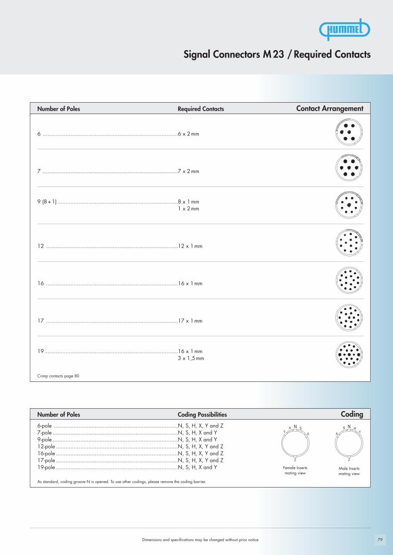
6 7 9 (8+1) 12 16 17 19 (16+3)
6 7 8 1 12 16 17 16 3
2 2 1 2 1 1 1 1 1,5
20 20 8 20 8 8 8 8 10
630 630 500 500 400 400 320
300 300 200 200 160 160 100
2500 2500 2500 2500 1500 1500 1500
> 1010 > 1010 > 1010 > 1010 > 106 > 106 > 106
3 3 3 3 3 3 3

Ø 2
6,2
2424
64,7
M 2
3 x
1
24 24
66,7
M 2
3 x
1
24
66,746 20,7
M 3
25 20,5
Ø 23 + 0,1
66,740,7 26
M 2
3 x
1M
25
x 1,
5
24
24Ø
30
Ø 25 + 0,1
66
Panel hole
Panel hole
3 – 7 mm (.12 – .28“).........7.106.400.0007 – 12 mm (.28 – .47“)......7.106.500.00011 – 17 mm (.44 – .67“).....7.106.600.000
Dimensions and specifications may be changed without prior notice
Straight Connector, Male Thread
Panel Connector, Male Thread, with Strain Relief
Panel Connector, Male Thread, with Strain Relief
Contacts and inserts page 74 • Assembly instructions page 88
Contacts and inserts page 74 • Assembly instructions page 88
Contacts and inserts page 74 • Assembly instructions page 88
Cable-Ø Part Number
Cable-Ø Part Number
Cable-Ø Part Number
Signal Connectors M 23 / Housing
Contacts and inserts page 74 • Assembly instructions page 88
Cable-Ø Part NumberStraight Connector, Female Thread
3 – 7 mm (.12 – .28“).........7.206.400.0007 – 12 mm (.28 – .47“)......7.206.500.00011 – 17 mm (.44 – .67“).....7.206.600.000
4 threads M 3, rear mounting 3 – 7 mm (.12 – .28“).........7.476.400.0007 – 12 mm (.28 – .47“)......7.476.500.00011 – 17 mm (.44 – .67“).....7.476.600.000
Optional: Flat gasket
Rear mounting, M 25 x 1,5 single hole mounted 3 – 7 mm (.12 – .28“).........7.486.400.0007 – 12 mm (.28 – .47“)......7.486.500.00011 – 17 mm (.44 – .67“).....7.486.600.000
Including jam nut M 25 x 1,5
max.
8 mm

73,5
Ø 26,2
2424
52
24
24
22
68,3
Ø 26,2
24 50
24 25
77,7
60
Ø 26,2
27
24
22
68,3
24 52
M 23 x 1
67Dimensions and specifications may be changed without prior notice
Contacts and inserts page 74 • Assembly instructions page 89
Contacts and inserts page 74 • Assembly instructions page 90
Contacts and inserts page 74 • Assembly instructions page 89
Cable-Ø Part Number
Cable-Ø Part Number
Cable-Ø Part Number
Right Angle Connector, Female Thread, EMC with positioning
Right Angle Connector, EMC, rotating
Right Angle Connector, Male Thread
Contacts and inserts page 74 • Assembly instructions page 89
3 – 7 mm (.12 – .28“).........7.300.300.0005 – 10 mm (.20 – .39“).......7.300.400.0007 – 12 mm (.28 – .47“).......7.300.500.00010 – 14 mm (.39 – .55“).....7.300.600.000
Cable-Ø Part Number Right Angle Connector, Female Thread with positioning
Signal Connectors M 23 / Housing
7 – 12 mm (.28 – .47“).......7.301.500.00010 – 14 mm (.39 – .55“).....7.301.600.000
7 – 12 mm (.28 – .47“).......7.306.500.00011 – 17 mm (.43 – .67“).....7.306.600.000
3 – 7 mm (.12 – .28“).........7.350.300.0005 – 10 mm (.20 – .39“).......7.350.400.0007 – 12 mm (.28 – .47“).......7.350.500.00010 – 14 mm (.39 – .55“).....7.350.600.000
Ø 20 + 0,1
Ø 2,7 / Ø 3,225 19
,8
M 23 x 1
22,5
Ø 19,8
M 2,5 / M 3
21,5
Ø 20 + 0,1
Ø 2,7 / Ø 3,2
25 19,8
21,5
M 23 x 1
22,5
Ø 19,8
M 2,5 / M 3
Ø 20 + 0,1
25 19,8
Ø 19,8
Ø 2,7 / Ø 3,2Ø 26,2
29,7 18
,533
,2
Ø 26,2
18,5
Ø 19,8
Ø 2,7 / Ø 3,2
Ø 20 + 0,1
25 19,8
68
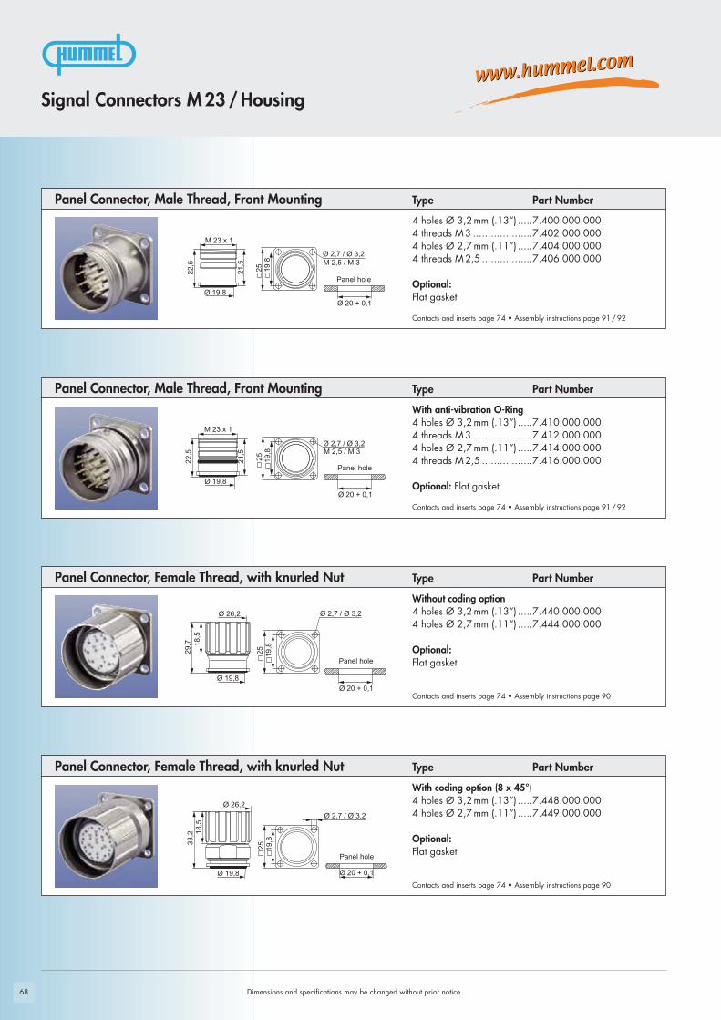
4 holes Ø 3,2 mm (.13“) .....7.400.000.0004 threads M 3 ....................7.402.000.0004 holes Ø 2,7 mm (.11“) .....7.404.000.0004 threads M 2,5 .................7.406.000.000
Optional: Flat gasket
With coding option (8 x 45°)4 holes Ø 3,2 mm (.13“) .....7.448.000.0004 holes Ø 2,7 mm (.11“) .....7.449.000.000
Optional: Flat gasket
Without coding option4 holes Ø 3,2 mm (.13“) .....7.440.000.0004 holes Ø 2,7 mm (.11“) .....7.444.000.000
Optional:Flat gasket
With anti-vibration O-Ring4 holes Ø 3,2 mm (.13“) .....7.410.000.0004 threads M 3 ....................7.412.000.0004 holes Ø 2,7 mm (.11“) .....7.414.000.0004 threads M 2,5 .................7.416.000.000
Optional: Flat gasket
Dimensions and specifications may be changed without prior notice
Contacts and inserts page 74 • Assembly instructions page 90
Type Part Number Panel Connector, Female Thread, with knurled Nut
Contacts and inserts page 74 • Assembly instructions page 90
Type Part Number Panel Connector, Female Thread, with knurled Nut
Contacts and inserts page 74 • Assembly instructions page 91 / 92
Type Part Number Panel Connector, Male Thread, Front Mounting
Contacts and inserts page 74 • Assembly instructions page 91 / 92
Type Part Number Panel Connector, Male Thread, Front Mounting
Signal Connectors M 23 / Housing
Panel hole
Panel hole
Panel hole
Panel hole

631
,5M 23 x 1
M 20 x 1,5 / PG 13,5
24
623
,5
M 23 x 1
M 20 x 1,5 / PG 13,5
24
PG 13,5: 20,6 + 0,1 M 20 x 1,5: 20,2 + 0,1
20,2+ 0,1
19,1
+0,
1
20,6+ 0,1
19,3
+0,
1
PG 13,5: 20,6 + 0,1 M 20 x 1,5: 20,2 + 0,1
20,2+ 0,1
19,1
+0,
1
20,6+ 0,1
19,3
+0,
1
M 23 x 1
29,5 23
,5
M 25 x 1,5
28Ø 25,2 + 0,1
25+ 0,1
24,1
+0,
1
6
69
FOR MALE
INSERTS ON
LY
FOR FEMALE
INSERTS ON
LY
Panel hole Panel hole
Panel hole Panel hole
Panel hole
Contacts and inserts page 74 • Assembly instructions page 91 / 92
For insert with pins/ socketsThread M 25 x 1,5 .............7.425.000.000
Optional: Flat gasket, jam nut M 25 x 1,5
Type Part Number Panel Connector, Male Thread, Single Hole Mounted
Panel Connector, Male Thread, Single Hole MountedType Part Number
Contacts and inserts page 74 • Assembly instructions page 92
Front mounting for female insertsThread M 20 x1,5 ..............7.421.000.000Thread PG 13,5 .................7.423.000.000
Optional: Flat gasket, jam nut M 20 x 1,5 / PG 13,5
Contacts and inserts page 74 • Assembly instructions page 91
Front mounting for male insertsThread M 20 x1,5 ..............7.420.000.000Thread PG 13,5 .................7.422.000.000
Optional: Flat gasket, jam nut M 20 x 1,5 / PG 13,5
Panel Connector, Male Thread, Single Hole MountedType Part Number
Signal Connectors M 23/ Housing
Dimensions and specifications may be changed without prior notice

Ø 19,8
29
50M
23
x 1
16,5
19,8
Ø 2,7
25
Ø 20 + 0,1
34,5
M 2
3 x
1
40,5
M 20 x 1,5
51,5
6
46
Ø 20,2 + 0,1
M 2
3 x
1
40,5
PG 13,5
46
51,5
6
Ø 20,6 + 0,1
43
51,5
Ø 3,219,825
22,628
37,5
49,5
M 2
3 x
1
Ø 20 + 0,1
Ø 2,7
70
Panel hole
Panel hole
Right Angle Panel Connector, Male Thread, rotating
Dimensions and specifications may be changed without prior notice
Contacts and inserts page 74 • Assembly instructions page 93
300° rotating, 1,5mm locking screw at flange4 x holes Ø 2,7 mm (.11“) ..7.433.000.000Flange 25 x 25mm
4 x holes Ø 3,2mm............7.433.100.000Flange 28 x 28mm
Type Part Number
Contacts and inserts page 74 • Assembly instructions page 93
335° rotating, hole mountedThread PG 13,5 .................7.432.000.000
Type Part Number Right Angle Panel Connector, Male Thread, rotating
Right Angle Panel Connector, Male Thread, rotating
Contacts and inserts page 74 • Assembly instructions page 93
Contacts and inserts page 74 • Assembly instructions page 93
335° rotating, hole mountedThread M 20 x 1,5 .............7.431.000.000
Type Part Number
Type Part Number
4 holes 2,7 mm (.11“).........7.435.000.000
Optional: Flat gasket
Easy fixation with M 2,5 screws
Right Angle Panel Connector, Male Thread
Signal Connectors M 23 / Housing
Panel hole
Panel hole

71
Ø 23 + 0,1
M 23 x 1
22,5 20,5
Ø 2,7 / Ø 3,2M 2,5 / M 3
Ø 2
5
Ø 23 + 0,1
22,5
M 23 x 1
Ø 2
0,5
Ø 2,7 / Ø 3,2M 2,5 / M 3
25
M 23 x 1M 25 x 1,5
30
29,5
Ø 25 + 0,1
25+ 0,1
24,1
+0,
1
31,5
24
Ø 26,2 4 x M 3
24,5
30
Ø 28 + 0,1
Dimensions and specifications may be changed without prior notice
Signal Connectors M 23 / Housing
Panel Connector, Male Thread, Rear MountingType Part Number
4 holes Ø 3,2 mm (.13“) .....7.450.000.0004 threads M 3 ....................7.452.000.0004 holes Ø 2,7 mm (.11“) .....7.454.000.0004 threads M 2,5 .................7.456.000.000
Optional: Flat gasket
Contacts and inserts page 74 • Assembly instructions page 91 / 92
Contacts and inserts page 74 • Assembly instructions page 91 / 92
With anti-vibration O-Ring4 holes Ø 3,2 mm (.13“) .....7.460.000.0004 threads M 3 ....................7.462.000.0004 holes Ø 2,7 mm (.11“) .....7.464.000.0004 threads M 2,5 .................7.466.000.000
Optional: Flat gasket
Panel Connector, Male Thread, Rear MountingType Part Number
Contacts and inserts page 74 • Assembly instructions page 91 / 92
Panel Connector, Male Thread, Single Hole MountedType Part Number
Rear mounting Thread M 25 x 1,5 .............7.458.000.000
Including jam nut M 25 x 1,5
With knurled nut, rear mounting4 threads M 3 ....................7.459.000.000
Type Part Number Panel Connector, Female Thread, Rear Mounting
Contacts and inserts page 74 • Assembly instructions page 90
Panel hole
Panel hole
Panel hole
Panel hole
max.
2,5 mm
max.
2,5 mm
max. 8 mm
max. 10 mm

51,6°
Ø 34
28
Ø 58
3,5
M 23 x 1
30,5
23
43° 3,5
30,5
Ø 34
28
23
Ø 70
M 23 x 1
3,5
29,3
Ø 34
28
23
M 23 x 1
33,68°
Ø 90
72 Dimensions and specifications may be changed without prior notice
Panel Connector with Radius Flange
Contacts and inserts page 74 • Assembly instructions page 91 / 92
With anti-vibration O-Ring and flat body gasketØ 90 mm (3.54“) ...............7.492.000.000
Type Part Number
Contacts and inserts page 74 • Assembly instructions page 91 / 92
With anti-vibration O-Ring and flat body gasketØ 70 mm (2.76“) ...............7.491.000.000
Type Part Number Panel Connector with Radius Flange
Contacts and inserts page 74 • Assembly instructions page 91 / 92
With anti-vibration O-Ring and flat body gasketØ 58 mm (2.28“) ...............7.490.000.000
Type Part Number Panel Connector with Radius Flange
Signal Connectors M 23 / Housing
for counter-sunk headscrews M3
for counter-sunk headscrews M3
for counter-sunk headscrews M3

46,4
Ø 2
6,2
22
74
Ø 2
6,2
56,5
M 2
3 x
1
M 23 x 1
78
Ø 26,2
M 2
3 x
1
M 2
3 x
152
,2
73
Closed type .......................7.105.000.000
Used to cap an open male connector in bus-systems
T 01 .................................7.T01
T 02 .................................7.T02
Signal Connectors M 23 / Housing
Type Part Number Signal Distribution
Contacts and inserts page 74
Contacts and inserts page 74
Type Part Number Signal Distribution
Bus End ConnectorType Part Number
Contacts and inserts page 74
Dimensions and specifications may be changed without prior notice
In case of so called Flying Connections it is often required to distribute, cross or combinesignals. Depending on the requirements of the application, the connections can be supplied either as male or female connector, or they can be configured with strain relieffittings. There are many possible combinations, including the internal wiring, independentof their style, as T-, Y-, H-, or other special configurations.
Signal Distribution

74
8,23
4,75
4,75
8,23
4,75
9,5
Dimensions and specifications may be changed without prior notice
Type Part Number Part Number
Pinout clockwise Pins SocketsInsert with solder contacts .........7.001.907.103.................7.001.907.104
Insert without contacts...............7.003.907.101.................7.003.907.102
Insert with dip solder contactsLength 3,5 mm .........................7.001.907.107
Insert with dip solder contactsLength 10 mm ..........................7.001.907.127.................7.001.907.108
Insert with dip solder contactsLength 17 mm ..........................7.001.907.137.................7.001.907.118
The correct dimension of a connector with dip solder contacts depends on the particulartype of housing.
Contacts page 80 • Coding possibilities N, S, H, X and Y (see page 79)
Insert socket mating view(Part P)
Insert pin mating view(Part E)
Inserts 7-pole
Contacts page 80 • Coding possibilities N, S, H, X and Y (see page 79)
Insert socket mating view(Part P)
Insert pin mating view(Part E)
Type Part Number Part NumberInserts 6-polePinout clockwise Pins SocketsInsert with solder contacts .........7.001.906.103.................7.001.906.104
Insert without contacts...............7.003.906.101.................7.003.906.102
Insert with dip solder contactsLength 3,5 mm .........................7.001.906.107
Insert with dip solder contactsLength 10 mm ..........................7.001.906.127.................7.001.906.108
Insert with dip solder contactsLength 17 mm ..........................7.001.906.137.................7.001.906.118
The correct dimension of a connector with dip solder contacts depends on the particulartype of housing.
Signal Connectors M 23 / Inserts / Pinouts
8,23
4,75
9,5
3,68,7
3,68,7
75
Signal Connectors M 23 / Inserts / Pinouts
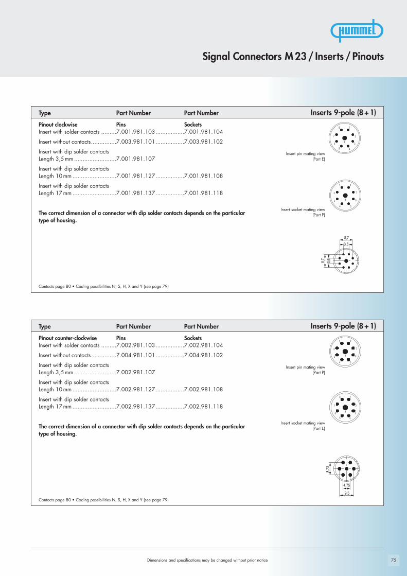
Type Part Number Part Number Inserts 9-pole (8+1)Pinout clockwise Pins SocketsInsert with solder contacts .........7.001.981.103.................7.001.981.104
Insert without contacts...............7.003.981.101.................7.003.981.102
Insert with dip solder contactsLength 3,5 mm .........................7.001.981.107
Insert with dip solder contactsLength 10 mm ..........................7.001.981.127.................7.001.981.108
Insert with dip solder contactsLength 17 mm ..........................7.001.981.137.................7.001.981.118
The correct dimension of a connector with dip solder contacts depends on the particulartype of housing.
Insert pin mating view(Part E)
Insert socket mating view(Part P)
Contacts page 80 • Coding possibilities N, S, H, X and Y (see page 79)
Type Part Number Part Number Inserts 9-pole (8+1)
Dimensions and specifications may be changed without prior notice
Contacts page 80 • Coding possibilities N, S, H, X and Y (see page 79)
Insert pin mating view(Part P)
Insert socket mating view(Part E)
Pinout counter-clockwise Pins SocketsInsert with solder contacts .........7.002.981.103.................7.002.981.104
Insert without contacts...............7.004.981.101.................7.004.981.102
Insert with dip solder contactsLength 3,5 mm .........................7.002.981.107
Insert with dip solder contactsLength 10 mm ..........................7.002.981.127.................7.002.981.108
Insert with dip solder contactsLength 17 mm ..........................7.002.981.137.................7.002.981.118
The correct dimension of a connector with dip solder contacts depends on the particulartype of housing.

76
3,8
9,8
11,1
9,87,1
14,3
4,5
1,9
5,55
6,5
3,6
3,8
9,8
11,1
9,87,1
14,3
4,5
1,9
5,55
6,5
3,6
Dimensions and specifications may be changed without prior notice
Contacts page 80 • Coding possibilities N, S, H, X and Y (see page 79)
Type Part Number Part NumberInserts 12-pole
Insert socket mating view(Part E)
Insert pin mating view(Part P)
Pinout counter-clockwise Pins SocketsInsert with solder contacts .........7.002.912.103.................7.002.912.104
Insert with solder contacts+PE (Pos.9)..............................7.002.912.113.................7.002.912.114
Insert without contacts...............7.004.912.101.................7.004.912.102
Insert without contacts+PE (Pos.9)..............................7.004.912.111.................7.004.912.112
Insert with dip solder contactsLength 3,5 mm .........................7.002.912.107
Insert with dip solder contactsLength 10 mm ..........................7.002.912.127.................7.002.912.108
Insert with dip solder contactsLength 17 mm ..........................7.002.912.137.................7.002.912.118
The correct dimension of a connector with dip solder contacts depends on the particulartype of housing.
Contacts page 80 • Coding possibilities N, S, H, X and Y (see page 79)
Insert socket mating view(Part P)
Insert pin mating view(Part E)
Type Part Number Part NumberInserts 12-polePinout clockwise Pins SocketsInsert with solder contacts .........7.001.912.103.................7.001.912.104
Insert with solder contacts+PE (Pos.9)..............................7.001.912.113.................7.001.912.114
Insert without contacts...............7.003.912.101.................7.003.912.102
Insert without contacts+PE (Pos.9)..............................7.003.912.111.................7.003.912.112
Insert with dip solder contactsLength 3,5 mm .........................7.001.912.107
Insert with dip solder contactsLength 10 mm ..........................7.001.912.127.................7.001.912.108
Insert with dip solder contactsLength 17 mm ..........................7.001.912.137.................7.001.912.118
The correct dimension of a connector with dip solder contacts depends on the particulartype of housing.
Signal Connectors M 23 / Inserts / Pinouts

5,1
10,4 6,1
3,4 8,8 11,4
0,75,71,1
2,8
2 3,65,54,8
2,5
3,4
9,05
5,454,56,5
10,9
11,9
0,85
31,25
6
23,942,51
5,755,04
77Dimensions and specifications may be changed without prior notice
Signal Connectors M 23 / Inserts / Pinouts
Type Part Number Part Number
Pinout clockwise Pins SocketsInsert with solder contacts .........7.001.916.103.................7.001.916.104
Insert without contacts...............7.003.916.101.................7.003.916.102
Insert with dip solder contactsLength 3,5 mm .........................7.001.916.107
Insert with dip solder contactsLength 10 mm ..........................7.001.916.127.................7.001.916.108
Insert with dip solder contactsLength 17 mm ..........................7.001.916.137.................7.001.916.118
The correct dimension of a connector with dip solder contacts depends on the particulartype of housing.
Inserts 16-pole
Insert pin mating view(Part E)
Insert socket mating view(Part P)
Contacts page 80 • Coding possibilities N, S, H, X and Y (see page 79)
Inserts 17-poleType Part Number Part Number
Pinout clockwise Pins SocketsInsert with solder contacts .........7.001.917.103.................7.001.917.104
Insert without contacts...............7.003.917.101.................7.003.917.102
Insert with dip solder contactsLength 3,5 mm .........................7.001.917.107
Insert with dip solder contactsLength 10 mm ..........................7.001.917.127.................7.001.917.108
Insert with dip solder contactsLength 17 mm ..........................7.001.917.137.................7.001.917.118
The correct dimension of a connector with dip solder contacts depends on the particulartype of housing.
Insert pin mating view(Part E)
Insert socket mating view(Part P)
Contacts page 80 • Coding possibilities N, S, H, X and Y (see page 79)

3,4
9,05
5,454,56,5
10,9
11,9
0,85
31,25
6
23,942,51
5,755,04
10,412
3
10,412
65,2
6
78 Dimensions and specifications may be changed without prior notice
Contacts page 80 • Coding possibilities N, S, H, X and Y (see page 79)
Insert socket mating view(Part P)
Insert pin mating view(Part E)
Type Part Number Part Number
Pinout clockwise Pins SocketsInsert with solder contacts .........7.001.919.103.................7.001.919.104
Insert with solder contacts+PE (Pos.12)............................7.001.919.113.................7.001.919.114
Insert with solder contacts + PE (Pos.12)1,5 mm elongated ....................7.001.919.123
Insert without contacts...............7.003.919.101.................7.003.919.102
Insert without contacts+PE (Pos.12)............................7.003.919.111.................7.003.919.112
Insert with dip solder contactsLength 3,5 mm .........................7.001.919.107
Insert with dip solder contactsLength 10 mm ..........................7.001.919.127.................7.001.919.108
Insert with dip solder contactsLength 17 mm ..........................7.001.919.137.................7.001.919.118
The correct dimension of a connector with dip solder contacts depends on the particulartype of housing.
Inserts 19-pole
Contacts page 80 • Coding possibilities N, S, H, X and Y (see page 79)
Insert socket mating view(Part E)
Insert pin mating view(Part P)
Type Part Number Part NumberInserts 17-polePinout counter-clockwise Pins SocketsInsert with solder contacts .........7.002.917.103.................7.002.917.104
Insert without contacts...............7.004.917.101.................7.004.917.102
Insert with dip solder contactsLength 3,5 mm .........................7.002.917.107
Insert with dip solder contactsLength 10 mm ..........................7.002.917.127.................7.002.917.108
Insert with dip solder contactsLength 17 mm ..........................7.002.917.137.................7.002.917.118
The correct dimension of a connector with dip solder contacts depends on the particulartype of housing.
Signal Connectors M 23 / Inserts / Pinouts
79
Z
YX
NS H
Z
XYNH S
Female Insertsmating view
Male Insertsmating view
7 ...................................................................................7 x 2mm
9 (8+1) ..........................................................................8 x 1mm.....................................................................................1 x 2mm
12 .................................................................................12 x 1mm
16 .................................................................................16 x 1mm
17 .................................................................................17 x 1mm
19..................................................................................16 x 1mm......................................................................................3 x 1,5mm
Dimensions and specifications may be changed without prior notice
As standard, coding groove N is opened. To use other codings, please remove the coding barrier.
Contact ArrangementNumber of Poles Required Contacts
Signal Connectors M 23 / Required Contacts
6-pole ............................................................................N, S, H, X, Y and Z7-pole .............................................................................N, S, H, X and Y9-pole .............................................................................N, S, H, X and Y12-pole ...........................................................................N, S, H, X, Y and Z16-pole ...........................................................................N, S, H, X, Y and Z17-pole ...........................................................................N, S, H, X, Y and Z19-pole ...........................................................................N, S, H, X and Y
CodingNumber of Poles Coding Possibilities
Crimp contacts page 80
6 ...................................................................................6 x 2mm
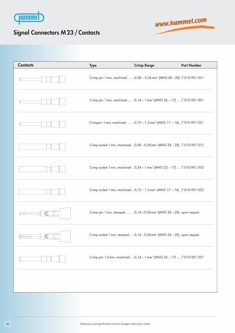
80 Dimensions and specifications may be changed without prior notice
Crimp pin 1 mm, machined .......0,14 – 1 mm2 (AWG 26 – 17) .....7.010.901.001
Crimppin 1 mm, machined ........0,75 – 1,5 mm2 (AWG 17 – 16) ..7.010.901.021
Crimp socket 1 mm, machined ...0,08 – 0,56 mm2 (AWG 28 – 20) ..7.010.901.012
Crimp socket 1 mm, machined ...0,34 – 1 mm2 (AWG 22 – 17) .....7.010.901.002
Crimp socket 1 mm, machined ...0,75 – 1,5 mm2 (AWG 17 – 16) ..7.010.901.022
Crimp pin 1 mm, stamped .........0,14 – 0,56 mm2 (AWG 26 – 20)..upon request
Crimp socket 1 mm, stamped.....0,14 – 0,56 mm2 (AWG 26 – 20)..upon request
Crimp pin 1,5 mm, machined ....0,14 – 1 mm2 (AWG 26 – 17) .....7.010.901.501
Crimp pin 1 mm, machined .......0,08 – 0,56 mm2 (AWG 28 – 20) .7.010.901.031
Type Crimp Range Part NumberContacts
Signal Connectors M 23 / Contacts

81
Crimp socket 1,5 mm, machined..0,14 – 0,56 mm2 (AWG 26 – 20)..7.010.901.512
Crimp socket 1,5 mm, machined..0,56 – 1 mm2 (AWG 20 – 17) .....7.010.901.502
Crimp pin 2 mm, machined .......0,75 – 2,5 mm2 (AWG 18 – 14) ..7.010.902.001
Crimp socket 2 mm, machined ...0,75 – 2,5 mm2 (AWG 18 – 14)..7.010.902.002
Type Crimp Range Part Number Contacts
Dimensions and specifications may be changed without prior notice
Signal Connectors M 23 / Contacts
Crimp Tool Settings see page 86

82
Signal Connector / Accessories
Dimensions and specifications may be changed without prior notice
Brass protective cap for connectors with female thread............................................................7.010.900.103
Brass protective cap for connectors with male thread ..............................................................7.010.900.102
Brass protective cap with chain for connectorswith female thread ...................Length 70 mm ....................7.010.9S0.703..............................................Length 100 mm ..................7.010.9S1.003
Brass protective cap with chain for connectorswith male thread ......................Length 70 mm ....................7.010.9S0.702..............................................Length 100 mm ..................7.010.9S1.002
Plastic protective capfor connectors with male thread .........................................7.000.900.101for connectors with female thread.......................................7.000.900.102
Assembly tool ..................................................................7.010.900.101
Type Part NumberAccessories

83
Locator for Crimp ToolDMC M22520 with positioner ....7.000.9DM.C03 ...............7.010.901.001, 7.010.901.501, 7.010.902.001
Locator for Crimp ToolDMC M22520 with positioner ....7.000.9DM.C04 ...............7.010.901.012, 7.010.901.002, 7.010.901.512,
7.010.901.502, 7.010.902.002
Locator Type Part Number for HUMMEL Contact
Type Part Number Accessories
Dimensions and specifications may be changed without prior notice
Operating instructions on page 84 - 86, 94
Adaptor flange for Straight Connectors .....................................................7.010.900.128
Snapflex 16.......................7.010.900.204DN 12 ..............................7.010.900.205Snapflex 20.......................7.010.900.206DN 14 ..............................7.010.900.207Snapflex 25.......................7.010.900.208DN 17 ..............................7.010.900.209
Adapter for Conduit Fittings
Crimp tool for manual crimping of machined crimp contactsfor signal connectors ........................................................7.000.900.904
Signal Connector / Accessories

84
Crimp jaws
Adjusting screw
with 0.01 mm incrementsScale indicating
0.2 mm increments
Physical stop
Dimensions and specifications may be changed without prior notice
Crimp Tool for Signal Connectors M 23 / M 16
Crimp Tool Type Part Number
Crimp tool............................................................7.000.900.904 / 7.000.900.907
ApplicationThe four indent crimp tool 7.000.900.904 / 7.000.900.907 has been developed foroptimal crimping of machined contacts with diameters from 0.08 to 2.5 mm2
(28 through 14 AWG).
How to CrimpThe reference table indicates the correct locator position to be selected and the crimpdepth to be adjusted for the contact to be crimped. The contact is then inserted throughthe access hole of the tool on the opposite side of the locator. The contact is held in placeby closing the handles to the first lock-in position thus preventing the contact from fallingout of the tool and facilitating insertion of the wire into the contact. The precision ratchet assures consistently accurate crimping every time by forcing the toolto be closed all the way completing the crimping cycle before the tool can be openedagain.
Exchange of the LocatorThe locator can be exchanged by removing the socket head cap screw with a socket wrench.It can then be disassembled from the hex head screw by turning it counter-clockwise.

85Dimensions and specifications may be changed without prior notice
Crimp Tool for Signal Connectors M 23 / M 16
Crimp ToolAdjustment of Crimp DepthCrimp depth can be adjusted as follows:Turn the adjusting screw clockwise for reducing the crimp depth and counter-clock-wise for increasing the crimp depth.
Adjustment Increments:- 1 space on the adjusting screw = adjustment by 0.01 mm- 1 full rotation of adjusting screw = adjustment by 0.2 mm (indication on the screw
as well as on the rough scale) - 5 rotations of the adjusting screw =adjustment by 1 mm (indication on the scale)
Control of Crimp DepthCrimp tool adjustment is done at the factory, but with frequent use, periodic calibra-tion is recommended to insure accuracy. This is easily accomplished with a 1.0 mm Øwire gauge as follows.A crimp depth of 1.0 mm is set by means of the adjusting screw (scale mark at „1“,screw mark at „0“ as shown in the fig. above) and the tool in the closed position.After insertion of the gauge, there must be just enough space for moving the gaugeinside the entry hole. If the opening is too small or too large to exactly match thegauge, the deviation (+/-) can be checked by the precision setting of the screw.Please contact the factory in case the deviation exceeds the tolerances specified bythe contract manufacturer.
Maintenance and RepairKeep the tool clean and properly stored when not in service. All pivot points need tobe oiled regularly and the spring clips securing the bolts have to always be in place.For repair please send the tool back to the factory.
Crimp depth -
Adjusting screw with 0.1 mm increments
Crimp depth +
Scale indicating 0.2 mm increments
^^
^
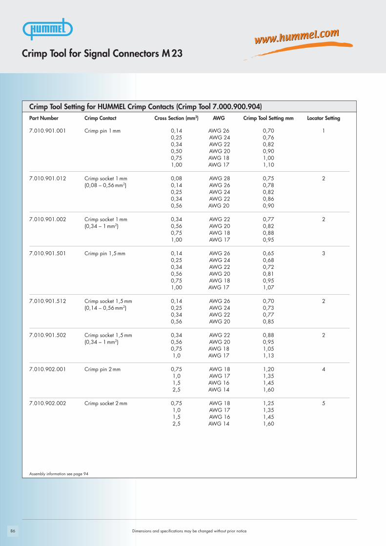
86
Part Number Crimp Contact Cross Section (mm2) AWG Crimp Tool Setting mm Locator Setting
7.010.901.001 Crimp pin 1 mm 0,14 AWG 26 0,70 10,25 AWG 24 0,760,34 AWG 22 0,820,50 AWG 20 0,900,75 AWG 18 1,001,00 AWG 17 1,10
7.010.901.012 Crimp socket 1 mm 0,08 AWG 28 0,75 2(0,08 – 0,56 mm2) 0,14 AWG 26 0,78
0,25 AWG 24 0,820,34 AWG 22 0,860,56 AWG 20 0,90
7.010.901.002 Crimp socket 1 mm 0,34 AWG 22 0,77 2(0,34 – 1 mm2) 0,56 AWG 20 0,82
0,75 AWG 18 0,881,00 AWG 17 0,95
7.010.901.501 Crimp pin 1,5 mm 0,14 AWG 26 0,65 30,25 AWG 24 0,680,34 AWG 22 0,720,56 AWG 20 0,810,75 AWG 18 0,951,00 AWG 17 1,07
7.010.901.512 Crimp socket 1,5 mm 0,14 AWG 26 0,70 2(0,14 – 0,56 mm2) 0,25 AWG 24 0,73
0,34 AWG 22 0,770,56 AWG 20 0,85
7.010.901.502 Crimp socket 1,5 mm 0,34 AWG 22 0,88 2(0,34 – 1 mm2) 0,56 AWG 20 0,95
0,75 AWG 18 1,051,0 AWG 17 1,13
7.010.902.001 Crimp pin 2 mm 0,75 AWG 18 1,20 41,0 AWG 17 1,351,5 AWG 16 1,452,5 AWG 14 1,60
7.010.902.002 Crimp socket 2 mm 0,75 AWG 18 1,25 51,0 AWG 17 1,351,5 AWG 16 1,452,5 AWG 14 1,60
Dimensions and specifications may be changed without prior notice
Crimp Tool Setting for HUMMEL Crimp Contacts (Crimp Tool 7.000.900.904)
Crimp Tool for Signal Connectors M 23
Assembly information see page 94

87
Part Number Crimp Contact Cross Section (mm2) AWG Crimp Tool Setting mm Locator Setting
7.010.901.031 Crimp pin 1 mm 0,08 0,72 10,14 0,780,25 0,820,34 0,860,56 0,90
7.010.901.021 Crimp pin 1 mm 0,75 0,80 11,00 0,861,50 0,95
7.010.901.022 Crimp socket 1 mm 0,75 0,80 21,00 0,861,50 0,95
Crimp Tool Setting for HUMMEL Crimp Contacts (Crimp Tool 7.000.900.904)
Dimensions and specifications may be changed without prior notice
Crimp Tool for Signal Connectors M 23
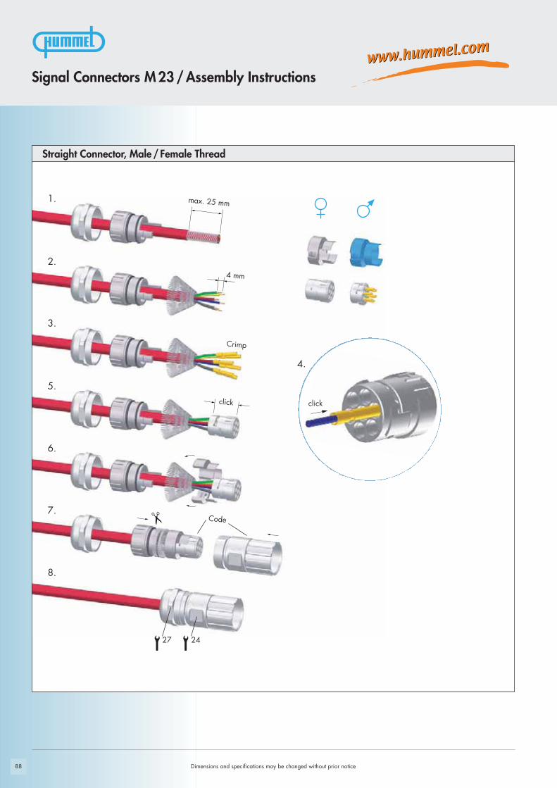
88
1.
2.
3.
5.
6.
7.
8.
4.
Dimensions and specifications may be changed without prior notice
Straight Connector, Male/ Female Thread
Signal Connectors M 23 / Assembly Instructions
Crimp
27 24
clickclick
Code
4 mm
max. 25 mm

89
1.
2.
3.
4.
6.
8.
7.
9.
10.
11.
12.
5.
Signal Connectors M 23 / Assembly Instructions
Dimensions and specifications may be changed without prior notice
Right Angle Connectors, EMC
Crimp
click
25
27 24
click
click
Code
4 mm
60 mm
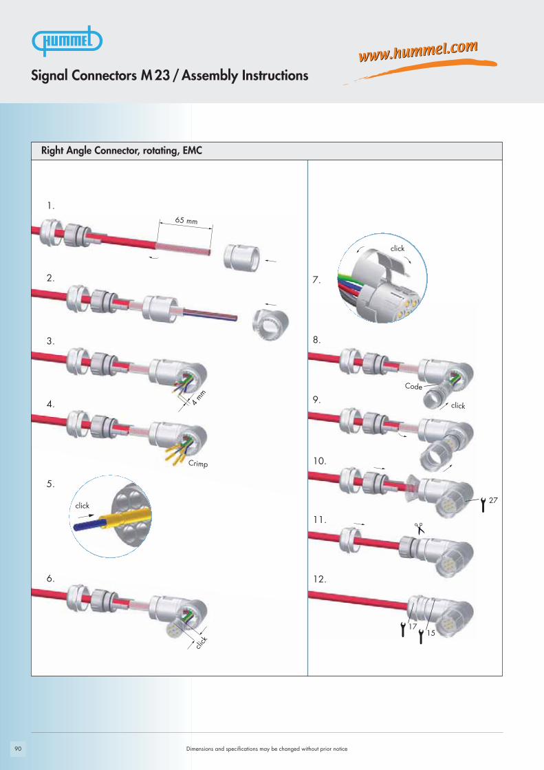
Crimp
90
1.
2.
3.
4.
5.
6.
8.
7.
9.
10.
11.
12.
Dimensions and specifications may be changed without prior notice
Right Angle Connector, rotating, EMC
Signal Connectors M 23 / Assembly Instructions
click
click
Crimp
Code
click
click
27
1715
4 mm
65 mm

1.
2.
4.
5.
6.
91
3.
Signal Connectors M 23 / Assembly Instructions
Dimensions and specifications may be changed without prior notice
Panel Connectors, Male Inserts
Crimp
Code
click
click
click
4 mm

92
3.
1.
2.
4.
5.
6.
Dimensions and specifications may be changed without prior notice
Signal Connectors M 23 / Assembly Instructions
Panel Connectors, Female Inserts
click
Crimp
Code
click
click
4 mm
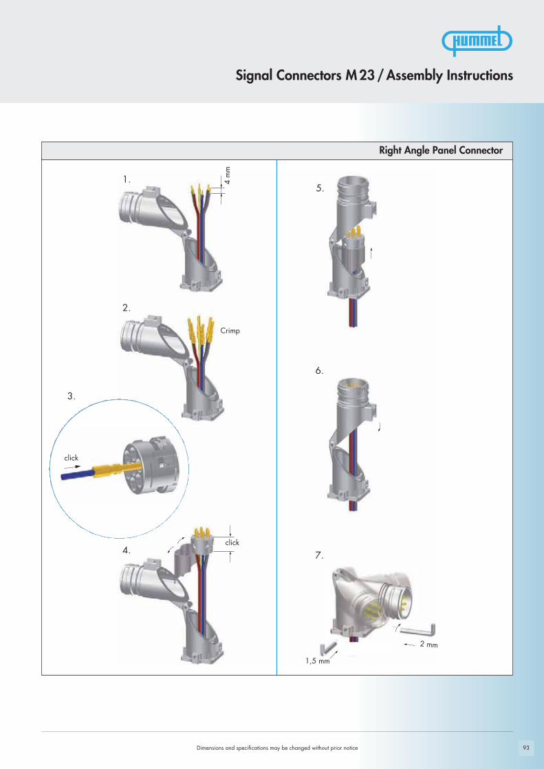
1.5.
2.
6.
3.
4. 7.
93Dimensions and specifications may be changed without prior notice
Signal Connectors M 23 / Assembly Instructions
Right Angle Panel Connector
Crimp
click
click
1,5 mm
2 mm
4 m
m

94
!
Dimensions and specifications may be changed without prior notice
Crimping, Assembly and Disassembly of ContactsCrimping- Remove conductor insulation 4 mm (.16“) max.- Select appropriate Crimp tool setting (see page 86)- Insert Crimp contact into the positioner of the tool- Insert stripped end of conductor into the crimp opening of the contact- Squeeze handles of crimp tool together
Assembly - Open crimping jaws and remove contact- Pry open upper and lower insert approx. 3 mm (1/8“) apart as shown- Insert the contact and conductor assembly into the desired location- Press upper and lower insert parts together
DisassemblyNo special tools are needed to remove the crimp contacts from the insert.
- Remove upper part of insert- With a pair of needle nose pliers, wiggle the contact and push it back through
the lower part of insert- Insert contacts into new location and push until it snaps in position- Align the nose and groove of the upper and lower part of insert and press together
Shielding- Assemble strain relief insert with insert- Fold stranding of the shield back over the first O-Ring of the strain relief insert- Cut back the overextending braid
The stranding of the shield is not allowed to touch the second O-Ring. Otherwise the assembly may not be proof.
Crimping, Assembly and Disassembly of Contacts

95
Setting Standards
Connectors M 27

96
1612
345
67 8 9
101112
131415
25SO
26
1718
1920 21
2223
24
161514
131211
109 8 7
654
321
25PO26
2423
2221 20
1918
17
1612
345
67 8 9
101112
131415
252827
SO26
1718
1920 21
2223
24
161514
131211
109 8 7
654
321
252728
PO26
2423
2221 20
1918
17
Dimensions and specifications may be changed without prior notice
Accessories page 101
page 99Inserts
page 98Housings
Product Overview

ÜBERSETZUNG IN ALL-LEN SPRACHEN FEHLT
97Dimensions and specifications may be changed without prior notice
Electrical Data
Housing Copper-Zinc alloy Die Casting
Housing surface Nickel platedother surface upon request
Inserts (for contacts) Thermoplastic Polyamid PA 6 (Nylon 6/6), PBT Fire protection class V-0
Contacts Brass Alloy
Contact surface at point of contact Nickel and gold plated (0,25μm Au)
Minimum mating cycles > 1000
Seals / O-Rings Buna-N standardoptional Viton® (Viton is a registered trademark of DuPont)
Temperature range -40° C – 125° C (-40 °F – 257 °F)
Type of contacts Crimp, solder, dip-solder (PCB)
Protection IP 67 / IP 69 K per EN 60 529 (connected), NEMA 4x
Cable diameter range 7 – 17 mm (.28 – .67“)
Materials and Technical DataMechanical Data
M 27 Signal Connectors
Technical Data
Number of positions
Number of contacts
Contact-Ø [mm]
Nominal current 1) [A]
Nominal voltage 2) [V~]
Test voltage (Breakdown voltage) 3) [V~]
Insulation resistance [MΩ]
Max. contact resistance [mΩ]
Degree of Protection 4)
1), 2), 3), 4) See Technical Informations page 14
26 28
26 28
1 1
8 8
150 150
1500 1500
> 1012 > 1012
3 3
3 3

Ø 3
0
74
27 25
27
M 2
7 x
1
25
78
27
Ø 3,2
Ø 22,8
M 27 x 1
26 25 30 23
Ø 23 + 0,1
98 Dimensions and specifications may be changed without prior notice
Contacts and inserts page 99 • Assembly instructions page 104
Type Part Number
Contacts and inserts page 99 • Assembly instructions page 103
Signal Connectors M 27 / Housing
Cable-Ø Part NumberStraight Connector, Male Thread
Contacts and inserts page 99 • Assembly instructions page 103
Cable-Ø Part NumberStraight Connector, Female Thread
4 x holes 3,2 mm................7.410.700.000
Panel Connector, Male Thread, front mounting
7 – 12 mm (.28 - .47”) ........7.210.500.00011 – 17 mm (.43 - .67”) ......7.210.600.000
7 – 12 mm (.28 - .47”) ........7.110.500.00011 – 17 mm (.43 - .67”) ......7.110.600.000
Panel hole

99
1612
3
4
567 8 9
101112
131415
25
SO
26
1718
1920 21
22
2324
161514
13
12
1110
9 8 765
4
321
25
PO
26
2423
2221 20
19
1817
1612
3
4
56
7 8 91011
12
131415
252827
SO
26
1718
1920 21
22
2324
161514
13
12
1110
9 8 765
4
321
252728
PO
26
2423
2221 20
19
1817
Signal Connectors M 27 / Housing
Dimensions and specifications may be changed without prior notice
Type Part Number Part Number Inserts 26-polePinout clockwise Pins SocketsInsert with solder contacts .........7.001.926.103.................7.001.926.104
Insert without contacts...............7.003.926.101.................7.003.926.102
Insert with dip solder contactsLength 3,5 mm .........................7.001.926.107
Insert with dip solder contactsLength 10 mm ..........................7.001.926.127
The correct dimension of a connector with dip solder contacts depends on the particulartype of housing.
Insert pin mating view
Insert socket mating view
Contacts page 100
Type Part Number Part Number Inserts 28-pole
Contacts page 100
Insert pin mating view
Insert socket mating view
Pinout clockwise Pins SocketsInsert with solder contacts .........7.001.928.103.................7.001.928.104
Insert with dip solder contactsLength 3,5 mm .........................7.001.928.107
Insert with dip solder contactsLength 10 mm ..........................7.001.928.127
The correct dimension of a connector with dip solder contacts depends on the particulartype of housing.

100
161514
13
12
1110
9 8 765
4
321
25
PO
26
2423
2221 20
19
1817
161514
13
12
1110
9 8 765
4
321
252728
PO
26
2423
2221 20
19
1817
Contacts Type Crimp Range Part Number
Dimensions and specifications may be changed without prior notice
Signal Connectors M 27 / required contacts
Crimp pin 1 mm, machined .......0,14 – 1 mm2 (AWG 26 – 17) .....7.010.971.001
Crimp socket 1 mm, machined ...0,14 – 1 mm2 (AWG 26 – 17) .....7.010.971.002
Contact Arrangement Number of Poles Required Contacts
26 .................................................................................26 x 1mm
28 .................................................................................28 x 1mm
Crimp Tool Settings see page 102

101
See page 118/119 for crimp tool instructions and page 102 proper setting
Plastic protective capfor connectors with male thread .........................................7.000.980.167for connectors with female thread.......................................7.000.980.168
Brass protective cap for connectors with female thread.......................................7.010.900.169
Brass protective cap with chain for connectors with female thread..............................................Length 70 mm ....................7.010.9S0.707
Brass protective cap for connectors with male thread .........................................7.010.900.170
Brass protective cap with chain for connectors with male thread..............................................Length 70 mm ....................7.010.9S0.708
Crimp tool for manual crimpingof machined crimp contacts. Works with contacts for power or signal M 27. ....................7.000.900.901
Assembly tool ..................................................................7.010.900.110
Dimensions and specifications may be changed without prior notice
Signal Connectors M 27 / Accessories
Type Part Number Accessories

102 Dimensions and specifications may be changed without prior notice
Crimp Tool for Signal Connectors M 27
Part Number Crimp Contact Cross Section mm2 AWG Crimp Tool Setting mm Locator Setting
7.010.971.001 Crimp pin (signal) 1 mm 0,14 26 0,70 10,25 24 0,80 10,34 22 0,88 10,50 20 0,95 10,75 18 1 1
1 17 1,03 1
7.010.971.002 Crimp socket (signal) 1 mm 0,14 26 0,70 40,25 24 0,80 40,34 22 0,88 40,50 20 0,95 40,75 18 1 4
1 17 1,03 4
Crimp Tool Setting for HUMMEL Crimp Contacts (Crimp Tool 7.000.900.901)

103
1.
2.
3.
4.
6.
7.
8.
5.
Dimensions and specifications may be changed without prior notice
Signal Connectors M27 / Assembly Instructions
Straight Connector, Female Thread
Crimp
Code
25
7.010.900.110
2527
click
6 mm
max. 35 mm

104
1.
2.
3.
4.
click
Crimpclick
6 mm
Panel Connector
Signal Connectors M27/Assembly Instructions
Dimensions and specifications may be changed without prior notice

105
Setting Standards
Power Connectors M 23

106
1
2 4
5
31
D
CB
A4
13
A
BC
D
4
5
4 2
1
Dimensions and specifications may be changed without prior notice
page 116Accessories
page 114Inserts
page 108Housings
Product Overview
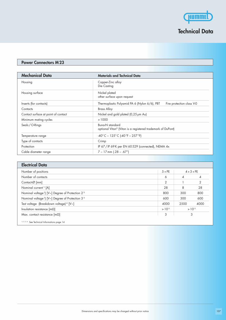
107107
5 + PE 4 + 3 + PE
6 4 4
2 1 2
28 8 28
800 300 800
600 300 600
4000 2500 4000
> 1013 > 1013
3 3
Technical Data
Power Connectors M 23
Materials and Technical DataMechanical Data
Electrical Data
Housing Copper-Zinc alloy Die Casting
Housing surface Nickel platedother surface upon request
Inserts (for contacts) Thermoplastic Polyamid PA 6 (Nylon 6/6), PBT Fire protection class V-0
Contacts Brass Alloy
Contact surface at point of contact Nickel and gold plated (0,25 μm Au)
Minimum mating cycles > 1000
Seals / O-Rings Buna-N standardoptional Viton® (Viton is a registered trademark of DuPont)
Temperature range -40° C – 125° C (-40 °F – 257 °F)
Type of contacts Crimp
Protection IP 67 / IP 69 K per EN 60 529 (connected), NEMA 4x
Cable diameter range 7 – 17 mm (.28 – .67“)
Dimensions and specifications may be changed without prior notice
Number of positions
Number of contacts
Contact-Ø [mm]
Nominal current 1) [A]
Nominal voltage 2) [V~] Degree of Protection 2 3)
Nominal voltage 2) [V~] Degree of Protection 3 3)
Test voltage (Breakdown voltage) 4) [V~]
Insulation resistance [mΩ]
Max. contact resistance [mΩ]
1), 2), 3), 4) See Technical Informations page 14

27
89,6
24
Ø 2
6,2
24 24
71,8
M 2
3 x
1
83,9
27 24
M 2
3 x
1
24 24
77,55
Ø 2
6,2
108
10 – 12 mm (.39 – .47“).....7.569.500.00011 – 17 mm (.43 – .67“).....7.569.600.000
7 – 12 mm (.24 – .47“).......7.560.500.00011 – 17 mm (.43 – .67“).....7.560.600.000
10 – 12 mm (.39 – .47“).....7.559.500.00011 – 17 mm (.43 – .67“).....7.559.600.000
7 – 12 mm (.24 – .47“).......7.550.500.00011 – 17 mm (.43 – .67“).....7.550.600.000
Dimensions and specifications may be changed without prior notice
Contacts and inserts page 114 • Assembly instructions page 122
Cable-Ø Part Number Straight Connector, Male Thread, MZ
Contacts and inserts page 114 • Assembly instructions page 122
Cable-Ø Part Number Straight Connector, Male Thread
Straight Connector, Female Thread, MZ Cable-Ø Part Number
Contacts and inserts page 114 • Assembly instructions page 122
Cable-Ø Part numberStraight Connector, Female Thread
Power Connectors M 23 / Housing
Contacts and inserts page 114 • Assembly instructions page 122

Ø 26,2
72,5
85
27 27
25
24
2578
72,5
Ø 26,2
27
2424
2268
62
M 23 x 1
77,6
62
M 23 x 1
25
22
24
109
9 – 12 mm (.35 – .47“).......7.589.500.00010 – 14 mm (.39 – .55“).....7.589.600.000
7 – 12 mm (.24 – .47“).......7.580.500.00010 – 14 mm (.39 – .55“).....7.580.600.000
9 – 12 mm (.35 – .47“).......7.579.500.00010 – 14 mm (.39 – .55“).....7.579.600.000
7 – 12 mm (.24 – .47“).......7.576.500.00011 – 17 mm (.43 – .67“).....7.576.600.000
Power Connectors M 23 / Housing
Cable-Ø Part Number Right Angle Connector, Female Thread, rotating
Contacts and inserts page 114 • Assembly instructions page 124
Cable-Ø Part Number Right Angle Connector, Female Thread, MZ, rotating
Contacts and inserts page 114 • Assembly instructions page 124
Cable-Ø Part Number Right Angle Connector, Male Thread, rotating
Contacts and inserts page 114 • Assembly instructions page 124
Contacts and inserts page 114 • Assembly instructions page 124
Cable-Ø Part Number Right Angle Connector, Male Thread, MZ, rotating
Dimensions and specifications may be changed without prior notice
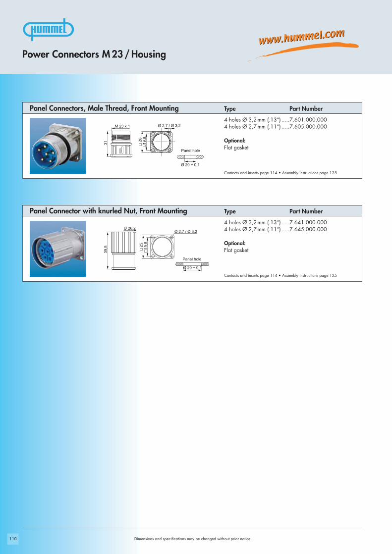
M 23 x 1
31
Ø 20 + 0,1
Ø 2,7 / Ø 3,2
2519
,8
Ø 26,2
39,5
Ø 20 + 0,1
19,8
26
Ø 2,7 / Ø 3,2
110 Dimensions and specifications may be changed without prior notice
Contacts and inserts page 114 • Assembly instructions page 125
4 holes Ø 3,2 mm (.13“) .....7.641.000.0004 holes Ø 2,7 mm (.11“) .....7.645.000.000
Optional: Flat gasket
Type Part Number Panel Connector with knurled Nut, Front Mounting
Contacts and inserts page 114 • Assembly instructions page 125
4 holes Ø 3,2 mm (.13“) .....7.601.000.0004 holes Ø 2,7 mm (.11“) .....7.605.000.000
Optional: Flat gasket
Type Part Number Panel Connectors, Male Thread, Front Mounting
Power Connectors M 23 / Housing
Panel hole
Panel hole

M 23 x 1
37,5
37,5
PG 13,5
266
Ø 20,6 + 0,1
20,6+ 0,1
19,3
+0,
1
37,5
6
M 20 x 1,5
M 23 x 1
26
Ø 20,2 + 0,1
20,2+ 0,1
19,1
+0,
1
M 25 x 1,5
32,5
M 23 x 1
7 28
Ø 25,2 + 0,1
25+ 0,1
24,1
+0,
1
M 23 x 1M 25 x 1,5
37,3
33,8
30
29
Ø 25 + 0,1
25+ 0,1
24,1
+0,
1
111Dimensions and specifications may be changed without prior notice
Contacts and inserts page 114 • Assembly instructions page 126
Rear mounting Thread M 25 x 1,5 .............7.651.000.000
Including jam nut M 25 x 1,5
Panel Connector, Male Thread, Single Hole Mounted
Panel Connector, Male Thread, Single Hole Mounted
Type Part Number
Contacts and inserts page 114 • Assembly instructions page 126
Front mounting Thread M 25x1,5 ...............7.626.000.000
Options: Flat gasket, jam nut M 25 x 1,5
Type Part Number
Contacts and inserts page 114 • Assembly instructions page 126
Front mounting Thread PG 13,5 .................7.623.000.000
Options: Flat gasket, jam nut PG 13,5
Type Part Number
Contacts and inserts page 114 • Assembly instructions page 126
Front mounting Thread M 20 x1,5 ..............7.621.000.000
Options: Flat gasket, jam nut M 20 x 1,5
Type Part Number
Panel Connector, Male Thread, Single Hole Mounted
Panel Connector, Male Thread, Single Hole Mounted
Power Connectors M 23 / Housing
Panel hole
Panel hole
Panel hole
Panel hole
max.
8 mm

54,5
29 M 2
3 x
1
Ø 19,8
19,8
Ø 2,7
25
34,5
Ø 20 + 0,1
40,5
54,5
M 20 x 1,5
M 2
3 x
1
46
6Ø 20,2 + 0,1
40,5
54,5
PG 13,5
M 2
3 x
1
46
6
Ø 20,6 + 0,1
Ø 20 + 0,1
Ø 2
,7
Ø 3
,2
19,825
22,628
37,543
54,552,5
M 2
3 x
1
112 Dimensions and specifications may be changed without prior notice
Contacts and inserts page 114 • Assembly instructions page 127
300° rotating, locking screw at flange4 x holes Ø 2,7 mm (.11“) ..7.638.000.000Flange 25 x 25mm
4 x holes Ø 3,2mm (.13“) ..7.638.100.000Flange 28 x 28mm
Type Part NumberRight Angle Panel Connector, Male Thread, rotating
Contacts and inserts page 114 • Assembly instructions page 127
335° rotating, single hole mountedThread PG 13,5 .................7.637.000.000
Type Part NumberRight Angle Panel Connector, Male Thread, rotating
Contacts and inserts page 114 • Assembly instructions page 127
335° rotating, single hole mountedThread M 20 x 1,5 .............7.636.000.000
Type Part NumberRight Angle Panel Connector, Male Thread, rotating
Contacts and inserts page 114 • Assembly instructions page 127
4 holes Ø 2,7 mm (.11“) .....7.635.000.000
Options: Flat gasket
Easy fastening with M 2,5 x 10 mm or #4 x .39“ long screws
Type Part NumberRight Angle Panel Connector, Male Thread
Power Connectors M 23 / Housing
Panel hole
Panel hole
Panel hole
Panel hole

34,5
M 23 x 1
32,5
Ø 3,2
25
Ø 23,1 + 0,1
20,5
M 2
3 x
1M
25
x 1,
5
71,5
25+ 0,1
24,1
+0,
1
33,8
3024 29
Ø 25 + 0,1
28,435
Ø 3,2
2846,5
78
Ø 2
6,2
24
24
M 2
3 x
1
18,547,571,5
28,4
35
Ø 3,2
113
Panel hole
Power Connectors M 23 / Housing
Panel Connector, Male Thread, Rear MountingType Part Number
With anti-vibration O-Ring4 holes Ø 3,2 mm (.13“) .....7.661.000.000
Contacts and inserts page 114 • Assembly instructions page 123
Cable-Ø Part Number
Single hole mounted, rear mounting, thread M 25 x 1,57 – 12 mm (.27 – .47“).......7.653.500.00011 – 17 mm (.43 – .67“).....7.653.600.000
Including jam nut M 25 x 1,5
Contacts and inserts page 114 • Assembly instructions page 122
Panel Connector, Male Thread, with Strain Relief
Panel Connector, Female Thread, with Strain ReliefCable-Ø Part Number
Contacts and inserts page 114 • Assembly instructions page 122
4 holes Ø 3,2 mm (.13“), front or rear mounting7 – 12 mm (.27 – .47“).......7.681.500.00011 – 17 mm (.43 – .67“).....7.681.600.000
Cable-Ø Part Number Panel Connector, Male Thread, with Strain Relief4 holes Ø 3,2 mm (.13“), front or rear mounting7 – 12 mm (.27 – .47“).......7.683.500.00011 – 17 mm (.43 – .67“).....7.683.600.000
Dimensions and specifications may be changed without prior notice
Contacts and inserts page 114 • Assembly instructions page 122
Panel hole
Panel hole
Panel hole
max.
12 mm
max.
14 mm
min. Ø 26,5 + 0,2
min. Ø 26,5 + 0,2

5
4 2
1
13
A
BC
D
4
31
D
CB
A4
1,85
6
4,85
7,05
11,41
4,1110,52
10,54
65,
63
2,86
2,86
1,85
6
4,85
7,05
11,41
4,1110,52
10,54
65,
63
2,86
2,86
114 Dimensions and specifications may be changed without prior notice
6 x crimp pins 2 mm .........................................................7.084.951.101
6 x crimp sockets 2 mm.....................................................7.084.951.102
4 x crimp pins 1 mm4 x crimp pins 2 mm .........................................................7.084.943.101
4 x crimp sockets 1 mm4 x crimp sockets 2 mm.....................................................7.084.943.102
Type of Contact Part NumberContact Arrangement, Mating View
Power Connectors M 23 / Inserts / Pinouts

115
Crimp pin 1 mm, machined 0,25 – 1 mm2.....................7.010.941.001(AWG 24 – 17)
Crimp socket 1 mm, machined 0,25 – 1 mm2.....................7.010.941.002(AWG 24 – 17)
Crimp pin 2 mm, machined 0,75 – 2,5 mm2..................7.010.942.001(AWG 18 – 14)
Crimp pin 2 mm, machined 2,5 – 4 mm2.......................7.010.942.011(AWG 14 – 12)
Power Connectors M 23 / Contacts
ContactsType of Contact Crimp Range Part Number
Dimensions and specifications may be changed without prior notice
See page 128 for crimp tool instructions and proper setting
Crimp socket 2 mm, machined 0,75 – 2,5 mm2..................7.010.942.002(AWG 18 – 14)
Crimp socket 2 mm, machined 2,5 – 4 mm2.......................7.010.942.012(AWG 14 – 12)

116
Power Connectors M 23 / Accessories
Dimensions and specifications may be changed without prior notice
Brass protective cap for connectors with female thread............................................................7.010.900.183
Brass protective cap for connectors with male thread ..............................................................7.010.900.102
Brass protective cap with chain for connectorswith female thread ...................Length 70 mm ....................7.010.9S0.783..............................................Length 100 mm ..................7.010.9S1.083
Brass protective cap with chain for connectorswith male thread ......................Length 70 mm ....................7.010.9S0.702..............................................Length 100 mm ..................7.010.9S1.002
Plastic protective capfor connectors with male thread .........................................7.000.900.101for connectors with female thread.......................................7.000.900.102
Type Part NumberAccessories
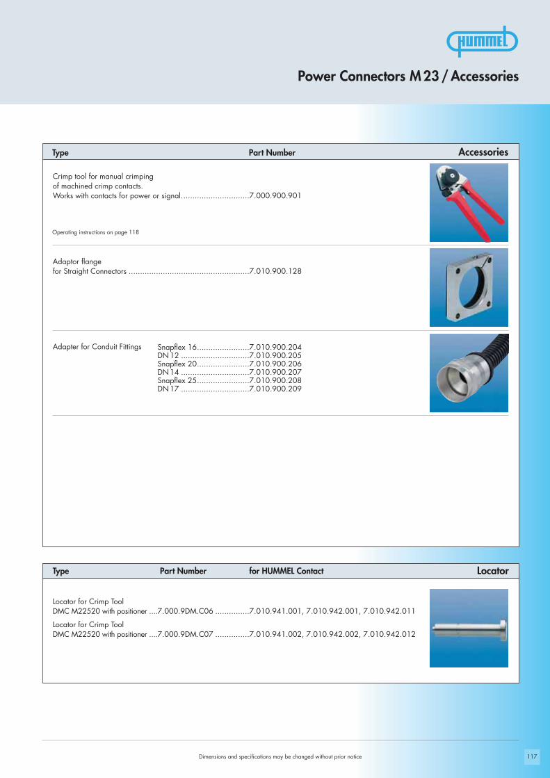
117
Locator for Crimp ToolDMC M22520 with positioner ....7.000.9DM.C06 ...............7.010.941.001, 7.010.942.001, 7.010.942.011
Locator for Crimp ToolDMC M22520 with positioner ....7.000.9DM.C07 ...............7.010.941.002, 7.010.942.002, 7.010.942.012
Locator Type Part Number for HUMMEL Contact
Type Part Number Accessories
Dimensions and specifications may be changed without prior notice
Operating instructions on page 118
Adaptor flange for Straight Connectors .....................................................7.010.900.128
Snapflex 16.......................7.010.900.204DN 12 ..............................7.010.900.205Snapflex 20.......................7.010.900.206DN 14 ..............................7.010.900.207Snapflex 25.......................7.010.900.208DN 17 ..............................7.010.900.209
Adapter for Conduit Fittings
Crimp tool for manual crimpingof machined crimp contacts. Works with contacts for power or signal..............................7.000.900.901
Power Connectors M 23 / Accessories
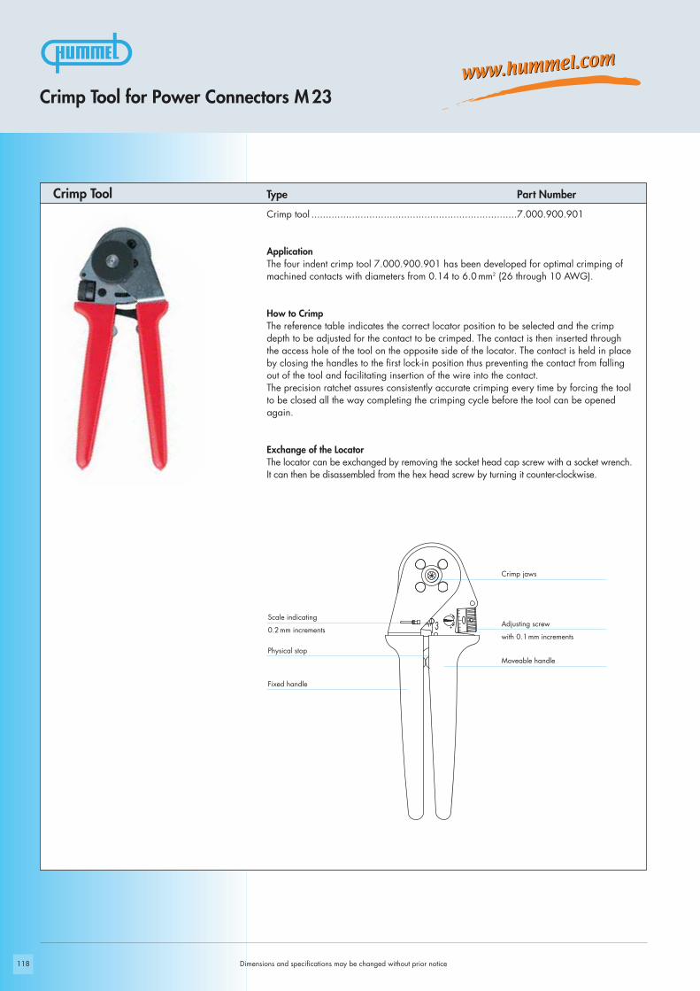
118
0
3
Dimensions and specifications may be changed without prior notice
Crimp jaws
Adjusting screw
with 0.1 mm increments
Scale indicating
0.2 mm increments
Crimp Tool Type Part Number
Crimp Tool for Power Connectors M 23
Crimp tool .......................................................................7.000.900.901
ApplicationThe four indent crimp tool 7.000.900.901 has been developed for optimal crimping ofmachined contacts with diameters from 0.14 to 6.0 mm2 (26 through 10 AWG).
How to CrimpThe reference table indicates the correct locator position to be selected and the crimpdepth to be adjusted for the contact to be crimped. The contact is then inserted throughthe access hole of the tool on the opposite side of the locator. The contact is held in placeby closing the handles to the first lock-in position thus preventing the contact from fallingout of the tool and facilitating insertion of the wire into the contact. The precision ratchet assures consistently accurate crimping every time by forcing the toolto be closed all the way completing the crimping cycle before the tool can be openedagain.
Exchange of the LocatorThe locator can be exchanged by removing the socket head cap screw with a socket wrench.It can then be disassembled from the hex head screw by turning it counter-clockwise.
Moveable handlePhysical stop
Fixed handle
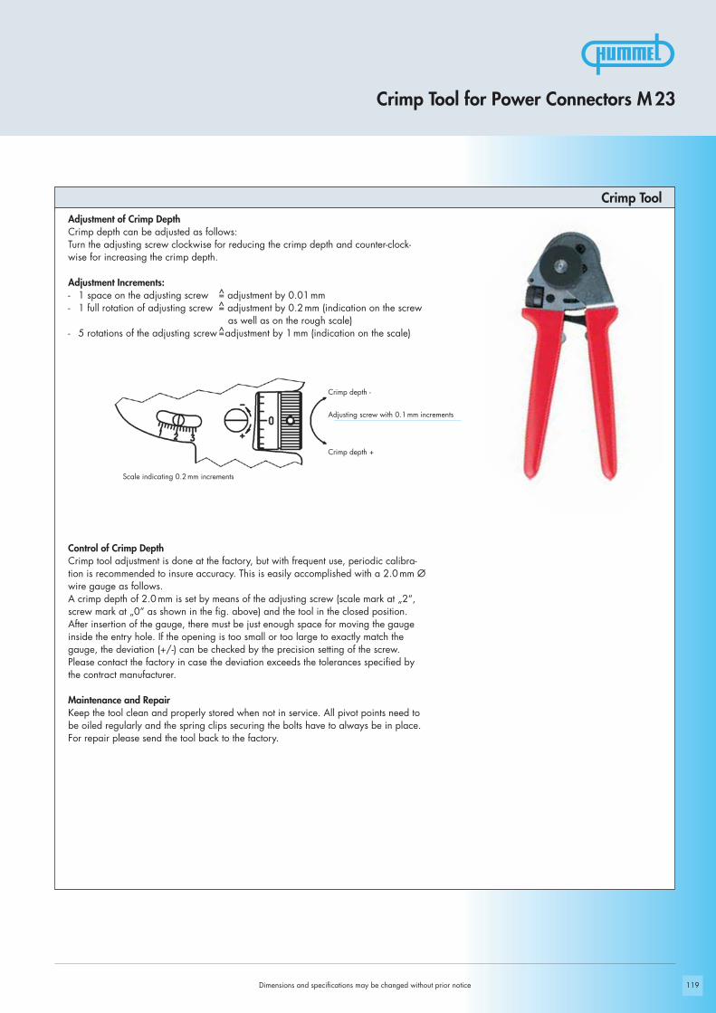
119
Crimp Tool for Power Connectors M 23
Crimp ToolAdjustment of Crimp DepthCrimp depth can be adjusted as follows:Turn the adjusting screw clockwise for reducing the crimp depth and counter-clock-wise for increasing the crimp depth.
Adjustment Increments:- 1 space on the adjusting screw = adjustment by 0.01 mm- 1 full rotation of adjusting screw = adjustment by 0.2 mm (indication on the screw
as well as on the rough scale) - 5 rotations of the adjusting screw =adjustment by 1 mm (indication on the scale)
Control of Crimp DepthCrimp tool adjustment is done at the factory, but with frequent use, periodic calibra-tion is recommended to insure accuracy. This is easily accomplished with a 2.0 mm Øwire gauge as follows.A crimp depth of 2.0 mm is set by means of the adjusting screw (scale mark at „2“,screw mark at „0“ as shown in the fig. above) and the tool in the closed position.After insertion of the gauge, there must be just enough space for moving the gaugeinside the entry hole. If the opening is too small or too large to exactly match thegauge, the deviation (+/-) can be checked by the precision setting of the screw.Please contact the factory in case the deviation exceeds the tolerances specified bythe contract manufacturer.
Maintenance and RepairKeep the tool clean and properly stored when not in service. All pivot points need tobe oiled regularly and the spring clips securing the bolts have to always be in place.For repair please send the tool back to the factory.
Dimensions and specifications may be changed without prior notice
Crimp depth -
Adjusting screw with 0.1 mm increments
Crimp depth +
Scale indicating 0.2 mm increments
^^
^

120 Dimensions and specifications may be changed without prior notice
Part Number Crimp Contact Cross Section mm2 AWG Crimp Tool Setting mm Locator Setting
7.010.901.001 Crimp pin (signal) 1 mm 0,14 26 0,75 110,25 24 0,82 110,35 22 0,9 110,50 20 1 110,75 18 1,08 111,0 17 1,2 11
7.010.901.012 Crimp socket (signal) 1 mm 0,14 26 0,75 120,25 24 0,8 120,35 22 0,87 120,50 20 0,97 12
7.010.901.002 Crimp socket (signal) 1 mm 0,50 20 0,95 120,75 18 1 121,0 17 1,05 12
7.010.901.501 Crimp pin (signal) 1,5 mm 0,14 26 0,75 30,25 24 0,82 30,35 22 0,9 30,50 20 0,96 30,75 18 1,03 31,0 17 1 3
7.010.901.512 Crimp socket (signal) 1,5 mm 0,14 26 0,75 40,25 24 0,8 40,35 22 0,87 40,50 20 0,97 4
7.010.901.502 Crimp socket (signal) 1,5 mm 0,50 20 0,95 40,75 18 1 41,0 17 1,05 4
7.010.902.001 Crimp pin (signal) 2 mm 0,75 18 1,3 51,0 17 1,4 51,5 16 1,55 52,5 14 1,75 5
7.010.902.002 Crimp socket (signal) 2 mm 0,75 18 1,3 61,0 17 1,4 61,5 16 1,55 62,5 14 1,75 6
7.010.941.001 Crimp pin (power) 1 mm 0,14 26 0,75 10,25 24 0,8 10,35 22 0,85 10,50 20 1,03 10,75 18 1,08 11,0 17 1,13 1
Crimp Tool Setting for HUMMEL Crimp Contacts (Crimp Tool 7.000.900.901)
Crimp Tool for Power Connectors M 23

121
These values are only guidelines and actual conductor cross sections depend on manufacturer tolerances.
Crimp Tool for Power Connectors M 23
Crimp Tool Setting for HUMMEL Crimp Contacts (Crimp Tool 7.000.900.901)Part Number Crimp Contact Cross Section mm2 AWG Crimp Tool Setting mm Locator Setting
7.010.941.002 Crimp socket (power) 1 mm 0,14 26 0,75 20,25 24 0,8 20,35 22 0,85 20,50 20 0,89 20,75 18 0,95 2
1 17 1,02 2
7.010.942.001 Crimp pin (power) 2 mm 0,75 18 1,3 71 17 1,4 7
1,5 16 1,55 72,5 14 1,7 7
7.010.942.011 Crimp pin (power) 2 mm 2,5 14 1,47 74 12 1,6 7
7.010.942.002 Crimp socket (power) 2 mm 0,75 18 1,3 81 17 1,4 8
1,5 16 1,55 82,5 14 1,7 8
7.010.942.012 Crimp socket (power) 2 mm 2,5 14 1,47 84 12 1,6 8
Dimensions and specifications may be changed without prior notice
Please see assembly instructions on page 128

122
! x
Dimensions and specifications may be changed without prior notice
Straight Connector, Female Thread
Power Connectors M 23 / Assembly Instructions
Contact 1mm = 4mmContact 2mm = 7mm
Crimp
x
max. 37 mm
click click
27 24
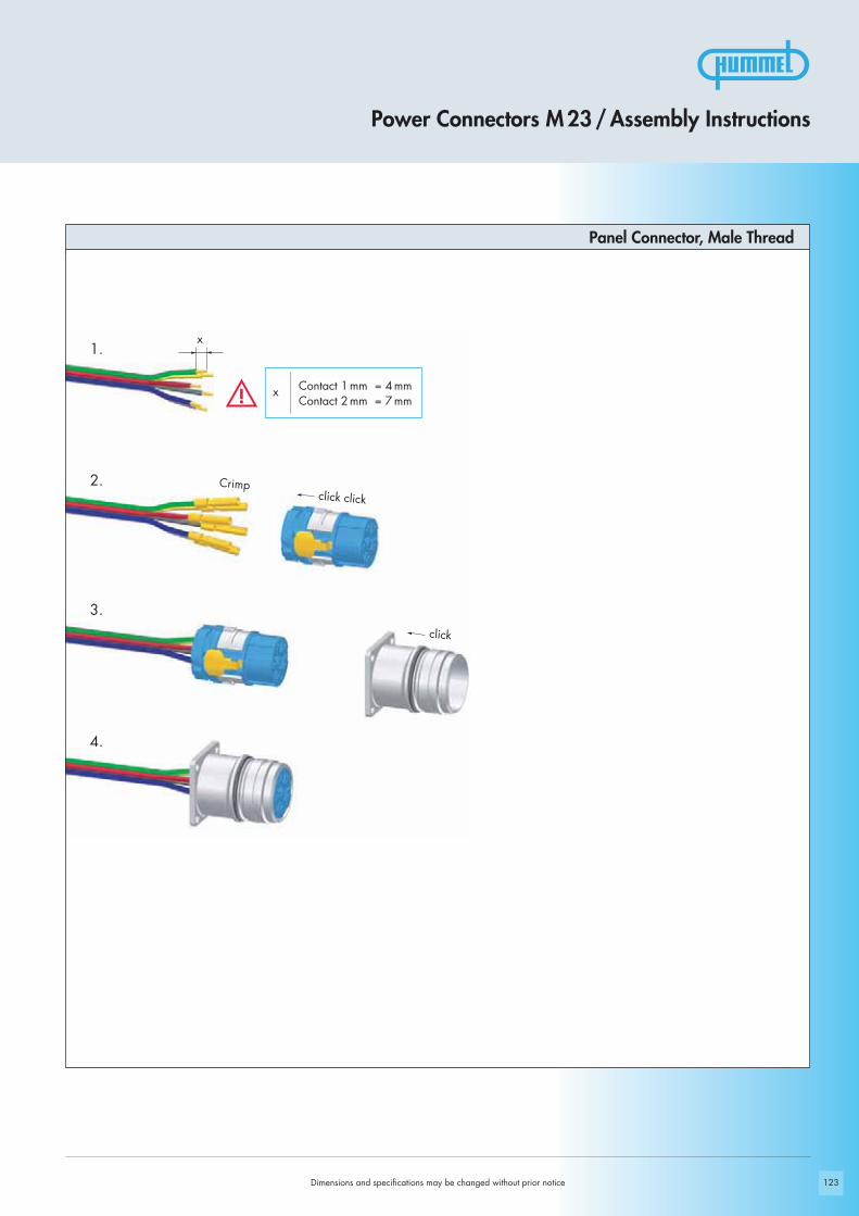
123
1.
2.
3.
4.
! x
Power Connectors M 23 / Assembly Instructions
Panel Connector, Male Thread
Dimensions and specifications may be changed without prior notice
Contact 1 mm = 4mmContact 2 mm = 7mm
Crimp
x
click click
click

124
! x
Dimensions and specifications may be changed without prior notice
Right Angle Connector, rotating
Power Connectors M 23 / Assembly Instructions
Contact 1mm = 4mmContact 2mm = 7mm
Crimp
65 mm
click click
27
27 25

125
1.
2.
3.
4.
! x
Power Connectors M 23 / Assembly Instructions
Dimensions and specifications may be changed without prior notice
Panel Connector, Female Thread
Contact 1mm = 4mmContact 2mm = 7mm
Crimp
x
click click
click

126
1.
2.
3.
4.
! x Contact 1mm = 4mmContact 2mm = 7mm
Dimensions and specifications may be changed without prior notice
Panel Connector, Male Thread, Single Hole Mounted
Power Connectors M 23 / Assembly Instructions
Crimp
x
click click
click

127
!
x
1. 4.
5.
6.
2.
3.
Contact 1mm = 4mmContact 2mm = 7mm
Power Connectors M 23 / Assembly Instructions
Dimensions and specifications may be changed without prior notice
Right Angle Panel Connector
Crimp
1,5 mm
2 mm
click click
x

128
!
Dimensions and specifications may be changed without prior notice
Crimping, Assembly and Disasembly
Crimping, Assembly and Disassembly
Crimping- For 1 mm contacts strip wire ends 4mm (.16“) max.,
for 2 mm contacts strip wire ends 7mm (.28“) max.- Dial appropriate setting of crimping tool (page 120/121)- Push crimp contact into opening of crimping tool- Insert stripped wire into the funnel shaped end of the crimp contact- Squeeze handles of crimping tool together, connecting contact to wire
Assembly- Remove crimped assembly and pull on wire to test connection- Push into desired position of insert
Note: For 8-pole inserts (4 + 3 + PE) it is recommended to assemble the large contacts first.
Disassembly of Contacts from InsertA small screw driver is required. - Using the screw driver, push the white clip ring out of the insert- Pull the contacts out of the insert- Replace the white clip ring- Reinsert the contacts
Disassembly of Insert from HousingA small screw driver is required. Push locking tongue, located above the PE-contact,down. By simultaneously pushing on the front side of the insert, it can be disassembledfrom the housing.
Shielding- Assemble strain relief insert with insert- Fold stranding of the shield back over the first O-Ring of the strain relief insert- Cut back the overextending braid
The stranding of the shield is not allowed to touch the second O-Ring. Otherwise the assembly may not be proof.

129
Setting Standards
Power Connectors Size 1,5 (M 40)

130
V- +
W U
V- +
W U
2 1
V+ -
U W
V+ -
U W
1 2
Dimensions and specifications may be changed without prior notice
page 135Inserts
page 132Housings
Product Overview
page 138Accessories

131
!
3 + 2 + PE 4 + 3 + PE
2 4 4 4
2 3,6 2 3,6
28 55 28 55
300 800 300 800
300 600 300 600
2500 4000 2500 4000
> 1013 > 1013
3 1 3 1
Standard delivery of M 40 (size 1.5) Power Connector include Contact Insert
Dimensions and specifications may be changed without prior notice
Electrical Data
Materials and Technical DataMechanical Data
Technical Data
Power Connectors Size 1,5 (M 40)
Housing Copper-Zinc alloy Die Casting
Housing surface Nickel plated, other surface upon request
Inserts (for contacts) Thermoplastic Polyamid PA 6 (Nylon 6/6), PBT Fire protection class V-0
Contacts Brass Alloy
Contact surface at point of contact Nickel and gold plated (0,25 μm Au)
Minimum mating cycles > 500
Seals / O-Rings Buna-N standardoptional Viton® (Viton is a registered trademark of DuPont)
Temperature range -40° C – 125° C (-40 °F – 257 °F)
Type of contacts Crimp
Protection IP 67 / IP 69 K per EN 60 529 (connected), NEMA 4x
Cable diameter range 13 – 28 mm (.51“ – 1.10“)
Number of positions
Number of contacts
Contact-Ø [mm]
Nominal current 1) [A]
Nominal voltage 2) [V~] Degree of Protection 2 3)
Nominal voltage 2) [V~] Degree of Protection 3 3)
Test voltage (Breakdown voltage) 4) [V~]
Insulation resistance [mΩ]
Max. contact resistance [mΩ]
1), 2), 3), 4) See Technical Informations page 14

111,2
Ø 4
6
40 38
111,2
Ø 4
6
40 38
132
V+ -
U W
V+ -
U W
1 2
40 38
118
M 4
0 x
1,5
V- +
W U
40 38
118
M 4
0 x
1,5
V- +
W U
2 1
Dimensions and specifications may be changed without prior notice
Contacts page 136 • Assembly instructions page 145
Contacts page 136 • Assembly instructions page 145
Contacts page 136 • Assembly instructions page 145
Straight Connector, Female Thread
Straight Connector, Male Thread
Straight Connector, Male Thread
Cable-Ø Part Number
Cable-Ø Part Number
Cable-Ø Part Number
Contacts page 136 • Assembly instructions page 145
Cable-Ø Part NumberStraight Connector, Female Thread
Power Connectors Size 1,5 (M 40)
2+ 3 + PE, insert for sockets13 – 18 mm (.51 – .71“) .....7.710.623.00017 – 24 mm (.67 – .97“) .....7.710.723.00021 – 28 mm (.83 – 1.10“) ...7.710.823.000
4 + 3 + PE, insert for sockets13 – 18 mm (.51 – .71“) .....7.710.643.00017 – 24 mm (.67 – .97“) .....7.710.743.00021 – 28 mm (.83 – 1.10“) ...7.710.843.000
2 + 3 + PE, insert for pins13 – 18 mm (.51 – .71“) .....7.720.623.00017 – 24 mm (.67 – .97“) .....7.720.723.00021 – 28 mm (.83 – 1.10“) ...7.720.823.000
4 + 3 + PE, insert for pins13 – 18 mm (.51 – .71“) .....7.720.643.00017 – 24 mm (.67 – .97“) .....7.720.743.00021 – 28 mm (.83 – 1.10“) ...7.720.843.000

133
Ø 32 + 0,1
51
M 40 x 1,5
30
40
Ø 4,5
Ø 32 + 0,1
51
M 40 x 1,5
30
40
Ø 4,5
V- +
W U
V- +
W U
2 1
40
40 30
Ø 4,5
44,2
Ø 45,6
Ø 32 + 0,1
40
40 30
Ø 4,5
44,2
Ø 45,6
Ø 32 + 0,1
V+ -
U W
V+ -
U W
1 2
Power Connectors Size 1,5 (M 40)
Dimensions and specifications may be changed without prior notice
Panel Connector, Male Thread, Front MountingType Part Number
Contacts page 136 • Assembly instructions page 146
2 + 3 + PE, insert for pins4 holes Ø 4,5 mm (.18“) .....7.740.023.000
Contacts page 136 • Assembly instructions page 146
Contacts page 136 • Assembly instructions page 146
Contacts page 136 • Assembly instructions page 146
4+ 3 + PE, insert for pins4 holes Ø 4,5 mm (.18“) .....7.740.043.000
2 + 3 + PE, insert for sockets4 holes Ø 4,5 mm (.18“) .....7.744.023.000
4+ 3 + PE, insert for sockets4 holes Ø 4,5 mm (.18“) .....7.744.043.000
Panel Connector, Male Thread, Front Mounting
Panel Connector with knurled Nut, Front Mounting
Panel Connector with knurled Nut, Front Mounting
Type Part Number
Type Part Number
Type Part Number
Panel hole
Panel hole
Panel hole
Panel hole

Ø 32 + 0,140 30
M 4
0 x
1,5
69
96
Ø 23
Ø 4,5
Ø 32 + 0,1
40 30
M 4
0 x
1,5
69
96
Ø 23
Ø 4,5
Ø 40,2 + 0,1
M 40 x 1,5
M 40 x 1,5
62,5 50
,512 28
Ø 40,2 + 0,1
M 40 x 1,5
M 40 x 1,5
62,5 50
,512 28
134
V- +
W U
V- +
W U
V- +
W U
2 1
V- +
W U
2 1
Type Part NumberPanel Connector, Male Thread, Single Hole Mounting
Type Part NumberPanel Connector, Male Thread, Single Hole Mounting
Front mounting, 2 + 3 + PE, insert for pinsThread M 40 x 1,5 .............7.742.023.000
Front mounting, 4 + 3 + PE, insert for pinsThread M 40 x 1,5 .............7.742.043.000
Dimensions and specifications may be changed without prior notice
Contacts page 136 • Assembly instructions page 147
Contacts page 136 • Assembly instructions page 146
Contacts page 136 • Assembly instructions page 146
4 + 3 + PE, insert for pins4 holes Ø 4,5 mm (.18“) .....7.743.043.000
Type Part NumberRight Angle Panel Connector, Male Thread, rotating
Contacts page 136 • Assembly instructions page 147
2 + 3 + PE, insert for pins4 holes Ø 4,5 mm (.18“) .....7.743.023.000
Type Part NumberRight Angle Panel Connector, Male Thread, rotating
Power Connectors Size 1,5 (M 40)
Panel hole
Panel hole
Panel hole
Panel hole
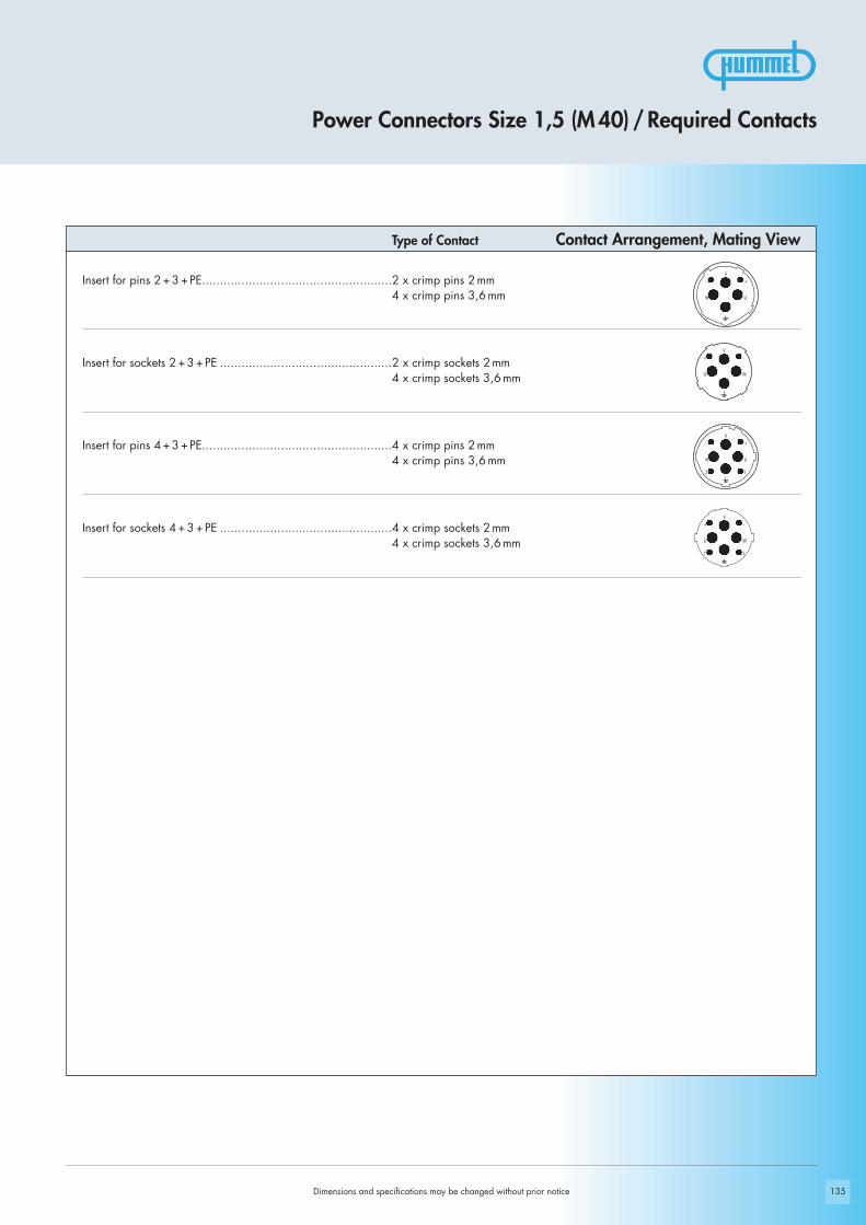
V- +
W U
V+ -
U W
V- +
W U
2 1
V+ -
U W
1 2
135Dimensions and specifications may be changed without prior notice
Insert for pins 2+ 3 + PE.....................................................2 x crimp pins 2 mm......................................................................................4 x crimp pins 3,6 mm
Insert for sockets 2 + 3 + PE ................................................2 x crimp sockets 2 mm......................................................................................4 x crimp sockets 3,6 mm
Insert for pins 4 + 3 + PE.....................................................4 x crimp pins 2 mm......................................................................................4 x crimp pins 3,6 mm
Insert for sockets 4 + 3 + PE ................................................4 x crimp sockets 2 mm......................................................................................4 x crimp sockets 3,6 mm
Type of Contact Contact Arrangement, Mating View
Power Connectors Size 1,5 (M 40) / Required Contacts

136 Dimensions and specifications may be changed without prior notice
Crimp socket 3,6 mm, machined..6 mm2 (AWG 10) ......................7.015.953.612
Crimp pin 3,6 mm, machined ....10 mm2 (AWG 8) ......................7.015.953.621
Crimp socket 3,6 mm, machined..10 mm2 (AWG 8) ......................7.015.953.622
Crimp pin 3,6 mm, machined ....6mm2 (AWG 10) ......................7.015.953.611
Crimp socket 3,6 mm, machined..1,5 – 4 mm2 (AWG 16 – 12) ......7.015.953.602
Crimp pin 3,6 mm, machined ....1,5 – 4 mm2 (AWG 16 – 12) ......7.015.953.601
Crimp socket 2 mm, machined ...0,5 – 4 mm2 (AWG 20 – 12) ......7.015.952.002
Crimp pin 2 mm, machined .......0,5 – 4 mm2 (AWG 20 – 12) ......7.015.952.001
Type of Contact Crimp Range Part NumberContacts
Power Connectors Size 1,5 (M 40) / Contacts
For appropriate setting of crimp tool see page 148

137
Crimp pin 3,6 mm, machined ....16 mm2 (AWG 6) ......................7.015.953.631
Crimp socket 3,6 mm, machined..16 mm2 (AWG 6) ......................7.015.953.632
For appropriate setting of crimp tool see page 148
Crimp Tool Settings see page 144
Power Connectors Size 1,5 (M 40) / Contacts
ContactsType Part Number
Dimensions and specifications may be changed without prior notice
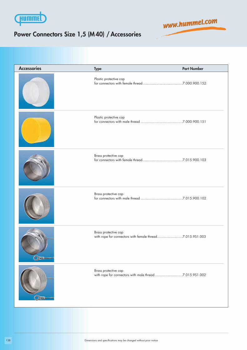
138 Dimensions and specifications may be changed without prior notice
Power Connectors Size 1,5 (M 40) / Accessories
Plastic protective capfor connectors with female thread.......................................7.000.900.152
Plastic protective capfor connectors with male thread .........................................7.000.900.151
Brass protective cap for connectors with female thread.......................................7.015.900.103
Brass protective cap for connectors with male thread .........................................7.015.900.102
Brass protective cap with rope for connectors with female thread.........................7.015.9S1.003
Brass protective cap with rope for connectors with male thread ...........................7.015.9S1.002
Type Part NumberAccessories

139
Snapflex 25.......................7.010.900.214DN 23 ..............................7.010.900.215Snapflex 32.......................7.010.900.216DN 29 ..............................7.010.900.217
Type Part Number Accessories
Dimensions and specifications may be changed without prior notice
Power Connectors Size 1,5 (M 40) / Accessories
Adaptor flange for Straight Connectors .....................................................7.010.900.129
Adapter for Conduit Fittings
Crimp tool for manual crimpingof machined crimp contacts up to 10 mm2 (AWG 8)for power connectors ........................................................7.000.900.902
Crimp tool for manual crimpingof machined crimp contacts 16mm2 (AWG 6) ......................7.000.900.903
See page 142 / 143 for crimp tool instructions and page 144 for proper setting
See page 140 / 141 for crimp tool instructions and page 144 for proper setting

NO.
1
140
Crimp tool .......................................................................7.000.900.902
ApplicationThe four indent crimp tool 7.000.900.902 has been developed for optimal crimping ofmachined contacts with diameters from 1 to 10 mm2 (18 through 8 AWG).
How to CrimpThe reference table indicates the correct locator position to be selected and the crimpdepth to be adjusted for the contact to be crimped. The contact is then inserted throughthe access hole of the tool on the opposite side of the locator. The contact is held in placeby closing the handles to the first lock-in position thus preventing the contact from fallingout of the tool and facilitating insertion of the wire into the contact. The precision ratchet assures consistently accurate crimping every time by forcing the toolto be closed all the way completing the crimping cycle before the tool can be openedagain.
Exchange of the LocatorThe locator can be exchanged by removing the socket head cap screw with a socket wrench.Then it can be disassembled from the hex head screw by turning it counter-clockwise.
Type Part NumberCrimp Tool
Crimp Tool for Power Connectors Size 1,5 (M 40)
Dimensions and specifications may be changed without prior notice
Safety clip
Selector knob
Tool in closed position
Tool in open position
Black
Red
Selector knob
Retainer ring
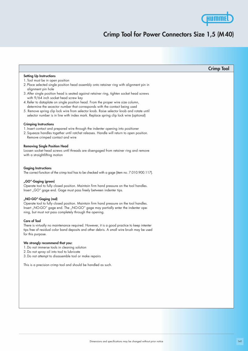
141
Crimp Tool
Crimp Tool for Power Connectors Size 1,5 (M 40)
Setting Up Instructions1.Tool must be in open position2.Place selected single position head assembly onto retainer ring with alignment pin in
alignment pin hole3.After single position head is seated against retainer ring, tighten socket head screws
with 9/64 inch socket head screw key4.Refer to dataplate on single position head. From the proper wire size column,
determine the secector number that corresponds with the contact being used5. Remove spring clip lock wire from selector knob. Raise selector knob and rotate until
selector number is in line with index mark. Replace spring clip lock wire (optional)
Crimping Instructions 1. Insert contact and prepared wire through the indenter opening into positioner2.Squeeze handles together until ratchet releases. Handle will return to open position.
Remove crimped contact and wire
Removing Single Position HeadLoosen socket head screws until threads are disengaged from retainer ring and removewith a straightlifting motion
Gaging InstructionsThe correct function of the crimp tool has to be checked with a gage (item no. 7.010.900.117).
„GO“-Gaging (green)Operate tool to fully closed position. Maintain firm hand pressure on the tool handles.Insert „GO“ gage end. Gage must pass freely between indenter tips.
„NO-GO“-Gaging (red)Operate tool to fully closed position. Maintain firm hand pressure on the tool handles.Insert „NO-GO“ gage end. The „NO-GO“ gage may partially enter the indenter ope-ning, but must not pass completely through the opening.
Care of ToolThere is virtually no maintenance required. However, it is a good practice to keep intentertips free of residual color band deposits and other debris. A small wire brush may be usedfor this purpose.
We strongly recommend that you:1.Do not immerse tools in cleaning solution2.Do not spray oil into tool to lubricate3.Do not attempt to disassemble tool or make repairs
This is a precision crimp tool and should be handled as such.
Dimensions and specifications may be changed without prior notice

142
Crimp Tool Type Part Number
Crimp tool for contacts 16 mm2 (AWG 6) ............................ 7.000.900.903
Application The hand crimp tool 7.000.900.903 has been developed for optimal crimping of a largevariety of connectors and terminals by using different interchangeable crimping dies.
Operation- Select crimp insert and install in tool- Insert and align crimp contact in tool- Compress tool until contact is held in place- Insert conductor into contact- Fully compress tool (tool will reopen automatically) - Remove crimped conductor from tool
Crimp Tool for Power Connectors Size 1,5 (M 40)
Dimensions and specifications may be changed without prior notice
Set screw
Emergency release
Die retaining screws
Adjustment wheel
Stationary jaw with upper die
Movable jaw with lower die

143
Crimp ToolAdjustment of crimp force and heightCrimp force adjustment is done in the factory (120 – 180N when unloaded). Toolframe and jaws are connected that way, an optimal crimping result will be obtainedbased on the hand force indicated above. In case the result (e.g. crimp height, pull-out force, etc.) does not meet the requirements of the plug manufacturer, the followingreasons can be considered:
a) Normal wear of tool Readjustment possible
b) Worn diesDies have to be replaced
The quality personnel is authorized to control and readjust these parameters asdescribed below:- Unscrew the set screw by means of a screw driver- Rotating the adjustment wheel anticlockwise, the crimp force increases
and the crimp height decreases ( + )- Rotating the adjustment wheel lockwise, the crimp force decreases
and the crimp height increases ( - )- When readjusting the hand force shall not exceed 180N- Before using the tool, the operator has to check the adjustment wheel being
firmly secured by the set screw
MaintenanceKeep the tool clean and properly stored when not in service. The joints need to beregularly oiled and the circlips securing the bolts have to be always in place. Neveruse abrasives or hard material to clean the jaws. Please contact the manufacturerwhen the tool needs to be repaired or in case of readjustment problems.
Crimp Tool for Power Connectors Size 1,5 (M 40)
Dimensions and specifications may be changed without prior notice

144
These values are only guidelines and actual conductor cross sections depend on manufacturer tolerances.
These values are only guidelines and actual conductor cross sections depend on manufacturer tolerances.
Assembly information see page 148
Assembly information see page 148
Crimp Tool for Power Connectors Size 1,5 (M 40)
Part Number Crimp Contact Cross Section mm2 AWG Crimp Tool Setting
7.015.953.631 Crimp pin 3,6 mm 16 6 die 16
7.015.953.632 Crimp socket 3,6 mm 16 6 die 16
Crimp Tool Setting for HUMMEL Crimp Contacts (Crimp Tool 7.000.900.902)
Crimp Tool Setting for HUMMEL Crimp Contacts (Crimp Tool 7.000.900.903)
Part Number Contact Cross Section mm2 AWG Crimp Tool Setting mm Locator Setting
7.015.952.001 Crimp pin 2mm 1 17 2 31,5 16 3 32,5 14 4 34 12 4 3
7.015.952.002 Crimp socket 2 mm 1 17 2 11,5 16 3 12,5 14 4 14 12 4 1
7.015.953.601 Crimp pin 3,6 mm 1,5 16 3 22,5 14 4 24 12 5 2
7.015.953.602 Crimp socket 3,6 mm 1,5 16 3 42,5 14 4 44 12 5 4
7.015.953.611 Crimp pin 3,6 mm 6 10 5 2
7.015.953.612 Crimp socket 3,6 mm 6 10 5 4
7.015.953.621 Crimp pin 3,6 mm 10 8 7 2
7.015.953.622 Crimp socket 3,6 mm 10 8 7 4
Dimensions and specifications may be changed without prior notice

145
1.
2.
3.
4.
5.
6.
7.
Dimensions and specifications may be changed without prior notice
Power Connectors Size 1,5 (M 40) /Assembly Instructions
Straight Connector, Female Thread / Male Threaded Connector
Crimpclick
7 mm
40 40
max. 40 mm

146
1.
2.
3.
4.
Dimensions and specifications may be changed without prior notice
Power Connectors Size 1,5 (M 40) /Assembly Instructions
Panel Connector
Crimpclick
7 mm

147
1.
2.
3.
4.
5.
6.
Right Angle Panel Connector
Dimensions and specifications may be changed without prior notice
Power Connectors Size 1,5 (M 40) /Assembly Instructions
Crimp
click
2 mm
3 mm
7 m
m

148
!
Dimensions and specifications may be changed without prior notice
Crimping, Assembly and Disassembly
Crimping, Assembly and Disassembly
Crimping- Strip wire ends 7 mm (.28“)- Dial appropriate setting of crimp tool (page 144)- Push crimp contact into opening of crimping tool- Insert stripped wire into the funnel shaped end of the crimp contact- Squeeze handles of crimping tool together connect contact to wire
Assembly- Remove crimped assembly and pull on wire to test connection- Push into desired position of insert
Note: It is recommended to assemble the large contacts first.
Disassembly of Contacts from InsertA small screwdriver is needed to remove the contacts from the insert.
- Release the white ring by a screwdriver out of the insert- Move the misplaced contacts out of the insert- Enter the ring back into the insert- Push the contacts back into insert
Shielding- Assemble strain relief insert with insert- Fold stranding of the shield back over the first O-Ring of the strain relief insert- Cut back the overextending braid
The stranding of the shield is not allowed to touch the second O-Ring. Otherwise the assembly may not be proof.

149
Setting Standards
TWILOCK

150
1
23
5
4 2
1
13
A
BC
D
4
Dimensions and specifications may be changed without prior notice
page 29, 82, 116Accessories
Inserts page 22, 74, 114
page 152Housings
Product Overview

151
!
Technical Data
TWILOCK Connectors
Mechanical DataHousing Copper-Zinc alloy
Die Casting
Housing surface Nickel plated, other surface upon request
Inserts (for contacts) Thermoplastic Polyamid PA 6 (Nylon 6/6), PBT Fire protection class V-0
Contacts Brass Alloy
Contact surface at point of contact Nickel and gold plated (0,25 μm Au)
Minimum mating cycles > 300
Seals / O-Rings Buna-N standardoptional Viton® (Viton is a registered trademark of DuPont)
Temperature range -40° C – 125° C (-40 °F – 257 °F)
Type of contacts M 16 Crimp, dip-solder (PCB)
Type of contacts signal M 23 Crimp, solder, dip-solder (PCB)
Type of contacts power M 23, M 40 Crimp
Protection IP 67 / IP 69 K per EN 60 529 (connected), NEMA 4x
Additional InformationElectrical data see standard programConnectors M16 page 17Signal Connectors M23 page 65Power Connectors M23 page 107
Characteristics
Dimensions and specifications may be changed without prior notice
Materials and Technical Data
We do not recommend disconnecting or connecting HUMMEL Connectors under load.
HUMMEL TWILOCK Connectors guarantee:
- Quick connecting cycle- High protection rate- Easy connection/disconnection even under tight space conditions
Inserts and contacts see standard programConnectors M16 page 22Signal Connectors M23 page 74Power Connectors M23 page 114

18 18
46
Ø 2
0,8
18 18
47,8
M 1
6 x
0,75
Ø 15 + 0,1 Ø 20 + 0,1
23,5
15M 16 x 0,75 20 19,8
25
Ø 2,7
Ø 2,7
152
28,5
41,2
M 1
6 x
0,75
36,5
31,7
1520 19,8
25
Ø 20 + 0,1Ø 14 + 0,1
Ø 2,7
Ø 2,7
Circular Connectors TWILOCK M 16
Dimensions and specifications may be changed without prior notice
Contacts and inserts page 22 • Assembly instructions page 34 / 35
Contacts and inserts page 22 • Assembly instructions page 38
Contacts and inserts page 22 • Assembly instructions page 39
Contacts and inserts page 22 • Assembly instructions page 34 / 35
Cable-Ø Part Number
Cable-Ø Part Number
Type Part Number
Type Part Number
Straight Connector, Female Thread
Straight Connector, Male Thread
Panel Connector, Male Thread, Front Mounting
Right Angle Panel Connector, Male Thread, rotating300° rotating, locking screw at flange4 x holes Ø 2,7 mm (.11“) ..7.843.000.000Flange 20 x 20mm
4 x holes Ø 2,7mm............7.843.100.000Flange 25 x 25mm
4 x holes Ø 2,7mm (.11“) ..7.840.000.000Flange 20 x 20mm
4 x holes Ø 2,7mm (.11“) ..7.840.100.000Flange 25 x 25mm
3 – 6 mm (.12 – .24“).........7.816.300.0005 – 9 mm (.20 – .35“).........7.816.400.0008 – 11 mm (.31 – .43“).......7.816.500.000
3 – 6 mm (.12 – .24“).........7.820.300.0005 – 9 mm (.20 – .35“).........7.820.400.0008 – 11 mm (.31 – .43“).......7.820.500.000
Panel hole Panel hole
Panel hole Panel hole
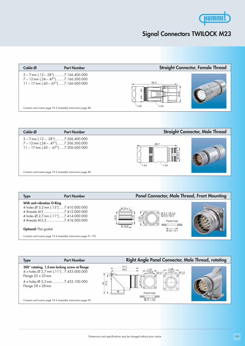
24
69,4
24
Ø 2
8M
23
x 1
24 24
66,7
Ø 20 + 0,1
Ø 2,7 / Ø 3,2
25 19,8
21,5
M 23 x 1
22,5
Ø 19,8
M 2,5 / M 3
153
43
51,5
Ø 3,219,825
22,628
37,5
49,5
M 2
3 x
1
Ø 20 + 0,1
Ø 2,7
Signal Connectors TWILOCK M23
Dimensions and specifications may be changed without prior notice
3 – 7 mm (.12 – .28“).........7.206.400.0007 – 12 mm (.24 – .47“).......7.206.500.00011 – 17 mm (.43 – .67“).....7.206.600.000
With anti-vibration O-Ring4 holes Ø 3,2 mm (.13“) .....7.410.000.0004 threads M 3 ....................7.412.000.0004 holes Ø 2,7 mm (.11“) .....7.414.000.0004 threads M 2,5 .................7.416.000.000
Optional: Flat gasket
300° rotating, 1,5mm locking screw at flange4 x holes Ø 2,7 mm (.11“) ..7.433.000.000Flange 25 x 25mm
4 x holes Ø 3,2mm............7.433.100.000Flange 28 x 28mm
3 – 7 mm (.12 – .28“)..........7.166.400.0007 – 12 mm (.24 – .47“)........7.166.500.00011 – 17 mm (.43 – .67“)......7.166.600.000
Contacts and inserts page 74 • Assembly instructions page 88
Contacts and inserts page 74 • Assembly instructions page 91 / 92
Contacts and inserts page 74 • Assembly instructions page 93
Contacts and inserts page 74 • Assembly instructions page 88
Cable-Ø Part Number Straight Connector, Female Thread
Straight Connector, Male Thread
Panel Connector, Male Thread, Front Mounting
Right Angle Panel Connector, Male Thread, rotating
Cable-Ø Part Number
Type Part Number
Type Part Number
Panel hole
Panel hole

154
24 24
76,4
Ø 2
8
Ø 20 + 0,1
Ø 2
,7
Ø 3
,2
19,825
22,628
37,543
54,552,5
M 2
3 x
1
M 23 x 1
31
Ø 20 + 0,1
19,8
26
Ø 2,7 / Ø 3,2
24 24
71,8
M 2
3 x
1
Dimensions and specifications may be changed without prior notice
Power Connectors TWILOCK M23
Panel hole
Panel hole
Straight Connector, Male Thread
Panel Connector, Male Thread, Front Mounting
Right Angle Panel Connector, Male Thread, rotating
Contacts and inserts page 114 • Assembly instructions page 122
Contacts and inserts page 114 • Assembly instructions page 125
Contacts and inserts page 114 • Assembly instructions page 127
Cable-Ø Part Number
Type Part Number
Type Part Number
Contacts and inserts page 114 • Assembly instructions page 122
Straight Connector, Female Thread Cable-Ø Part Number
7 – 12 mm (.24 – .47“).......7.560.500.00011 – 17 mm (.43 – .67“).....7.560.600.000
4 holes Ø 3,2 mm (.13“) .....7.601.000.0004 holes Ø 2,7 mm (.11“) .....7.605.000.000
Optional: Flat gasket
300° rotating, locking screw at flange4 x holes Ø 2,7 mm (.11“) ..7.638.000.000Flange 25 x 25mm
4 x holes Ø 3,2mm (.13“) ..7.638.100.000Flange 28 x 28mm
7 – 12 mm (.24 – .47“).......7.556.500.00011 – 17 mm (.43 – .67“).....7.556.600.000

155
Setting Standards
Push-Pull Technology Size M 40
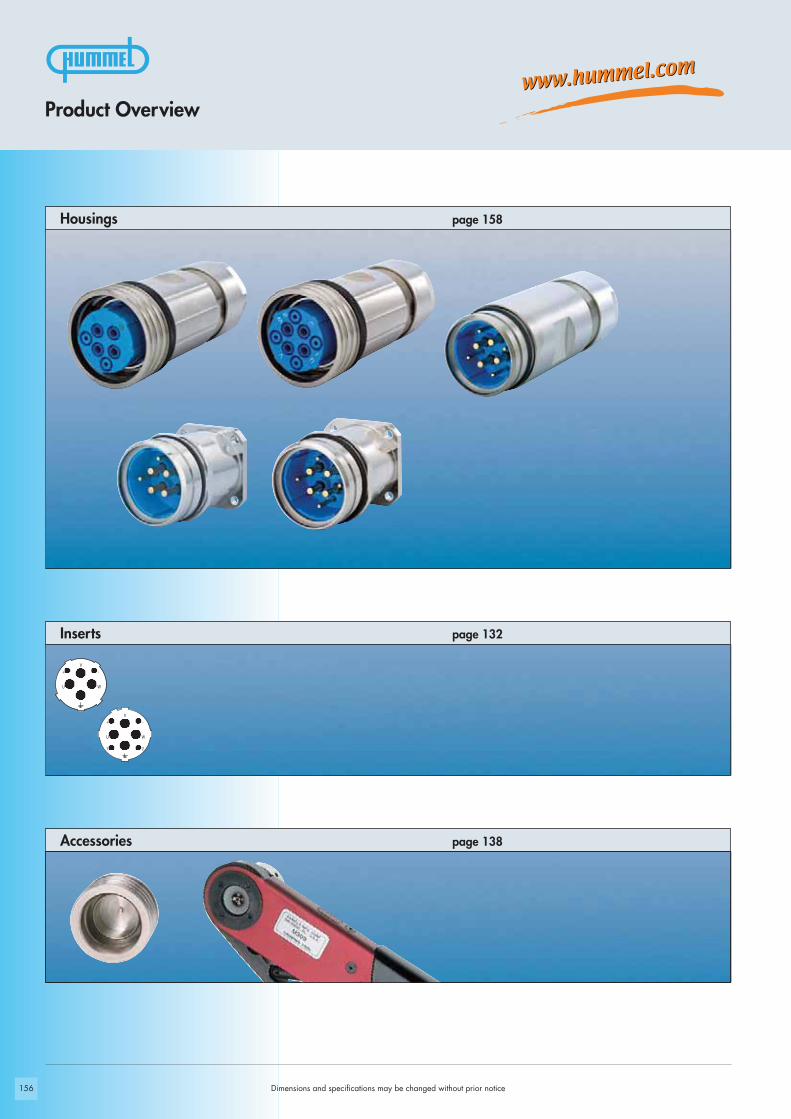
156
V+ -
U W
V+ -
U W
1 2
Dimensions and specifications may be changed without prior notice
page 138Accessories
Inserts page 132
page 158Housings
Product Overview

157
!
! Standard delivery of M 40 (size 1.5) Power Connector include Contact Insert
Technical Data
Push-Pull Connectors
Mechanical DataHousing Copper-Zinc alloy
Die Casting
Housing surface Nickel plated, other surface upon request
Inserts (for contacts) Thermoplastic Polyamid PA 6 (Nylon 6/6), PBT Fire protection class V-0
Contacts Brass Alloy
Contact surface at point of contact Nickel and gold plated (0,25 μm Au)
Minimum mating cycles > 250
Seals / O-Rings Buna-N standardoptional Viton® (Viton is a registered trademark of DuPont)
Temperature range -40° C – 125° C (-40 °F – 257 °F)
Type of contacts power M 40 Crimp
Protection IP 67 / IP 69 K per EN 60 529 (connected), NEMA 4x
Additional InformationElectrical data see standard programPower Connectors Size 1,5 page 131
Characteristics
Dimensions and specifications may be changed without prior notice
Materials and Technical Data
We do not recommend disconnecting or connecting HUMMEL Connectors under load.
HUMMEL Push-Pull Connectors guarantee:
- Quick connecting cycle- EMC compatible connection due to radially locked metal ring- High protection rate- Easy connection/disconnection even under tight space conditions- Best reliability with optional safety ring
Inserts and contacts see standard programPower Connectors Size 1,5 page 132

158
Ø 4
8,3
40
111
38
Ø 4
8,3
40
111
38
V+ -
U W
V+ -
U W
1 2
Dimensions and specifications may be changed without prior notice
Straight Connector, Female Thread
Straight Connector, Female Thread Cable-Ø Part Number
Cable-Ø Part Number
Contacts page 136 • Assembly instructions page 145
Contacts page 136 • Assembly instructions page 145
4+3+PE, insert for sockets13 – 18mm (.52 – .71“).....7.715.643.00017 – 24mm (.67 – .95“).....7.715.743.00021 – 28mm (.83 – 1.10“)...7.715.843.000
Optional: Safety ring
2+3+PE, insert for sockets13 – 18mm (.52 – .71“).....7.715.623.00017 – 24mm (.67 – .95“).....7.715.723.00021 – 28mm (.83 – 1.10“)...7.715.823.000
Optional: Safety ring
Power Connectors Size 1,5/Push-Pull
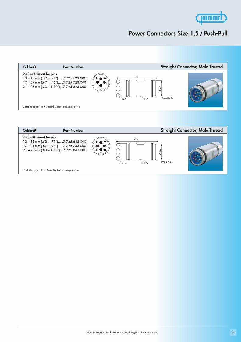
159
4040
110
Ø 4
04040
110
Ø 4
0
V- +
W U
V- +
W U
2 1
Dimensions and specifications may be changed without prior notice
Power Connectors Size 1,5/Push-Pull
Cable-Ø Part Number Straight Connector, Male Thread
Cable-Ø Part Number Straight Connector, Male Thread
Contacts page 136 • Assembly instructions page 145
Contacts page 136 • Assembly instructions page 145
Panel hole
Panel hole
2+3+PE, insert for pins13 – 18mm (.52 – .71“).....7.725.623.00017 – 24mm (.67 – .95“).....7.725.723.00021 – 28mm (.83 – 1.10“)...7.725.823.000
4+3+PE, insert for pins13 – 18mm (.52 – .71“).....7.725.643.00017 – 24mm (.67 – .95“).....7.725.743.00021 – 28mm (.83 – 1.10“)...7.725.843.000

160
51
Ø 4,5
3040
Ø 40
Ø 32 + 0,140
51
Ø 4,5
3040
Ø 40
Ø 32 + 0,140
V- +
W U
V- +
W U
2 1
Power Connectors Size 1,5/Push-Pull
Panel Connector
Panel Connector Type Part Number
Type Part Number
Contacts page 136 • Assembly instructions page 146
Contacts page 136 • Assembly instructions page 146
4+3+PE, insert for pins4 holes Ø 4,5mm (.18“) .....7.740.543.000
2+3+PE, insert for pins4 holes Ø 4,5mm (.18“) .....7.740.523.000
Panel hole
Panel hole
Dimensions and specifications may be changed without prior notice

161
Setting Standards
Stainless Steel Connectors (INOX)
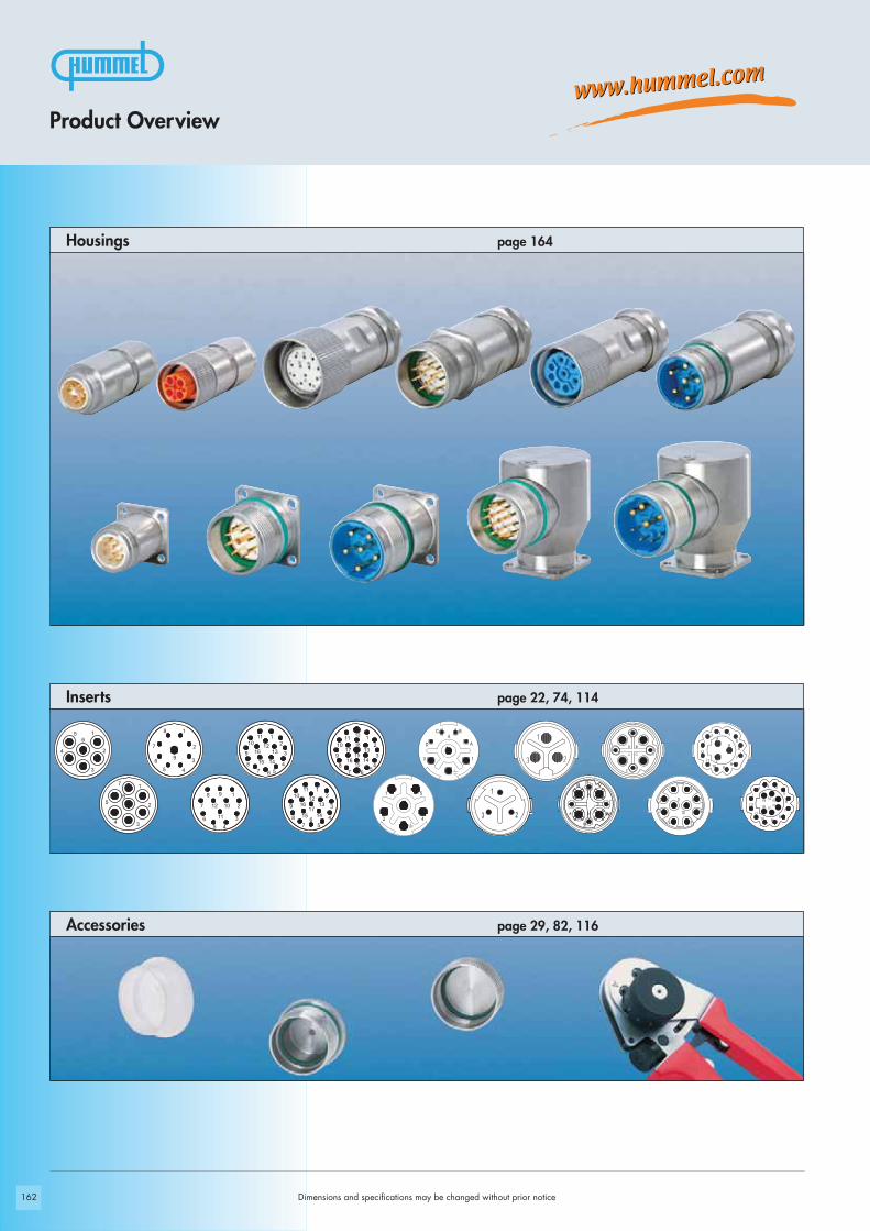
162
1
2 4
5
13
A
BC
D
4
1
23
Dimensions and specifications may be changed without prior notice
Accessories page 29, 82, 116
page 22, 74, 114Inserts
page 164Housings
Product Overview

163
!
Materials and Technical Data
Dimensions and specifications may be changed without prior notice
Technical Data
Connectors Stainless Steel (INOX)
Mechanical DataHousing Stainless Steel V4A 1.4404 (AISI 316 L)
Housing surface Clear
Inserts (for contacts) Thermoplastic Polyamid PA 6 (Nylon 6/6), PBT Fire protection class V-0
Contacts Brass Alloy
Contact surface at point of contact Nickel and gold plated (0,25 μm Au)
Minimum mating cycles > 1000
Seals / O-Rings Viton (FPM), alternativ EPDM
Temperature range -40° C – 125° C
Type of contacts signal M23 Crimp, solder, dip-solder (PCB)
Type of contacts power M 23 Crimp
Type of contacts M 16 Crimp, dip-solder (PCB)
Protection IP 67 / IP 69 K per EN 60 529 (connected), NEMA 4x
Additional Information
Typical Applications
We do not recommend disconnecting or connecting HUMMEL Connectors under load.
Electrical data see standard program Connectors M 16 page 17Signal Connectors M 23 page 65Power Connectors M 23 page 107
Inserts and contacts see standard program Connectors M 16 page 22Signal Connectors M 23 page 74Power Connectors M 23 page 114

Ø 1
9,7
18 18
46,3
M 1
6 x
0,75
18 18
47,9
164
23,5
15M 16 x 0,75 20
Ø 2,7
Ø 15 + 0,1
4 x holes Ø 2,7mm (.11“) ..7.840.400.000Flange 20 x 20mm
Dimensions and specifications may be changed without prior notice
Contacts and inserts page 22 • Assembly instructions page 38
Type Part NumberPanel Connector, Male Thread
Contacts and inserts page 22
Straight Connector, Male Thread Cable-Ø Part Number
Straight Connector, Female Thread
Contacts and inserts page 22
Cable-Ø Part Number
Signal Connectors M 16/Stainless Steel (INOX)
3 – 6 mm (.12“ – .24“) .......7.814.300.0005 – 9 mm (.20“ – .35“) .......7.814.400.0008 – 11 mm (.31“ – .43“) .....7.814.500.000
3 – 6 mm (.12“ – .24“) .......7.824.300.0005 – 9 mm (.20“ – .35“) .......7.824.400.0008 – 11 mm (.31“ – .43“) .....7.824.500.000
Panel hole

40,2
50
M 2
3 x
1
Ø 19,8
Ø 2,7
Ø 20 + 0,1
25 19,8
M 2
3 x
1
61,5
22
24
Ø 20 + 0,1
Ø 3,2
21,5
M 23 x 1
22,5
Ø 19,8
25 19,8
59
Ø 2
6,2
24 22
165
Signal Connectors M 23/Stainless Steel (INOX)
3 – 7 mm (.12 – .28“).........7.140.300.000.................7.141.300.0005 – 10 mm (.20 – .39“).......7.140.400.000.................7.141.400.0007 – 12 mm (.24 – .47“).......7.140.500.000.................7.141.500.00010 – 14 mm (.39 – .55“).....7.140.600.000.................7.141.600.000
Cable-Ø Part Number Part Number EMC Panel Connector, Male Thread
Contacts and inserts page 74 • Assembly instructions page 168
3 – 7 mm (.12 – .28“).........7.240.300.000.................7.241.300.0005 – 10 mm (.20 – .39“).......7.240.400.000.................7.241.400.0007 – 12 mm (.24 – .47“).......7.240.500.000 ................7.241.500.00010 – 14 mm (.39 – .55“).....7.240.600.000 ................7.241.600.000
Contacts and Inserts page 74
Cable-Ø Part Number Part Number EMC Right Angle Panel Connector, Male Thread
Dimensions and specifications may be changed without prior notice
With anti-vibration O-Ring4 holes Ø 3,2 mm (.13“) .....7.410.400.000
Type Part Number Panel Connector, Male Thread
Contacts and inserts page 74 • Assembly instructions page 91 / 92
4 holes Ø 2,7 mm (.11“) .....7.430.400.000
Contacts and Inserts page 74
Type Part Number Right Angle Panel Connector, Male Thread
Panel hole
Panel hole
Assembly tool 7.010.900.127 is required

74,8
Ø 2
6
M 2
3 x
1
69,6
Ø 20 + 0,1
32,5
M 23 x 1Ø 3,2
25 19,8
Ø 20 + 0,1
40,2
50
Ø 19,8
Ø 2,7
M 2
3 x
125 19
,8
166
7 – 12 mm (.24 – .47“).......7.564.500.00011 – 17 mm (.43 – .67“).....7.564.600.000
7 – 12 mm (.24 – .47“).......7.554.500.00011 – 17 mm (.43 – .67“).....7.554.600.000
Dimensions and specifications may be changed without prior notice
Contacts and Inserts page 114
4 holes Ø 2,7 mm (.11“) .....7.630.400.000
Type Part NumberRight Angle Panel Connector, Male Thread
Contacts and inserts page 114 • Assembly instructions page 123
For front mounting4 holes Ø 3,2 mm (.13“) .....7.601.400.000
Optional: Flat gasket
Type Part NumberPanel Connector, Male Thread
Straight Connector, Male Thread
Contacts and inserts page 114 • Assembly instructions page 122
Cable-Ø Part Number
Contacts and inserts page 114 • Assembly instructions page 122
Cable-Ø Part NumberStraight Connector, Female Thread
Power Connectors M 23/Stainless Steel (INOX)
Panel hole
Panel hole

167
Operating instructions on page 31
Operating instructions on page 85
Assembly tool ..................................................................7.010.900.127
Plastic protective capfor connectors M 16 with male thread .................................7.000.980.161for connectors M 16 with female thread ..............................7.000.980.162
for connectors M 23 with male thread .................................7.000.900.101for connectors M 23 with female thread ..............................7.000.900.102
Stainless steel protective cap for connectors with female thread............................................................7.010.904.103
Stainless steel protective cap with rope for connectorswith female thread ...................Length 100 mm ..................7.010.9S4.103
Stainless steel protective cap for connectors with male thread ..............................................................7.010.904.102
Stainless steel protective cap with rope for connectorswith male thread ......................Length 100 mm ..................7.010.9S4.102
Crimp tool for manual crimping of machined crimp contactsfor signal connectors ........................................................7.000.900.901
Crimp tool for manual crimping of machined crimp contactsfor signal connectors M 16 and M 23 .................................7.000.900.904
Dimensions and specifications may be changed without prior notice
Type Part Number Accessories
Stainless Steel Connectors (INOX)/Accessories

168
1.
2.
3.
4.
5.
6.
8.
7.
9.
10.
11.
12.
Dimensions and specifications may be changed without prior notice
Straight Signal Connector, Female Thread
Stainless Steel Connectors (INOX) / Assembly Instructions
Crimp
7.010.900.127
22
22
24
click
click
Code
20 mm
10 mm
4 mm
click

169
Setting Standards
Moulded Cordsets

170
1
2 4
5
13
A
BC
D
4 1
23
Dimensions and specifications may be changed without prior notice
page 29, 82 and page 116Accessories
Inserts
Moulded connector cordsets page 172
page 22, 74 and page 114
Product Overview

171
!
!
Other versionsMoulded connector cordsets are also available as Stainless-Steel (Inox)-Versions.
Materials and Technical Data
Technical Data
Moulded Connector Cordsets
Mechanical Data
Additional InformationElectrical data see standard program Connectors M 16 page 17Signal Connectors M 23 page 65Power Connectors M 23 page 107
Inserts and contacts see standard program Connectors M 16 page 22Signal Connectors M 23 page 74Power Connectors M 23 page 114
Dimensions and specifications may be changed without prior notice
Housing Copper-Zinc alloy Die Casting
Moulded strain relief Polyurethan PUR
Housing surface Nickel plated brass, black strain relief
Inserts (for contacts) Thermoplastic Polyamid PA 6 (Nylon 6/6), PBT Fire protection class V-0
Contacts Brass Alloy
Contact surface at point of contact Nickel and gold plated (0,25 μm Au)
Minimum mating cycles > 1000
Seals / O-Rings Buna-N standardoptional Viton® (Viton is a registered trademark of DuPont)
Temperature range -40° C – 125° C (-40 °F – 257 °F)
Type of contacts Crimp
Protection IP 67 / IP 69 K per EN 60 529 (connected), NEMA 4x
Cable style Cable specifications available upon request
Labelling HUMMEL logo as standard, other options available upon request
We do not recommend disconnecting or connecting HUMMEL Connectors under load.

50
M 1
6 x
0,75
M 16 x 0,75
40
41
172 Dimensions and specifications may be changed without prior notice
Moulded Connector Cordsets M 16
Right Angle Connector, Female ThreadStandard / EMC ................Pins or sockets
Type Inserts
Standard / EMC .................Pins or sockets
Type InsertsStraight Connector, Female Thread
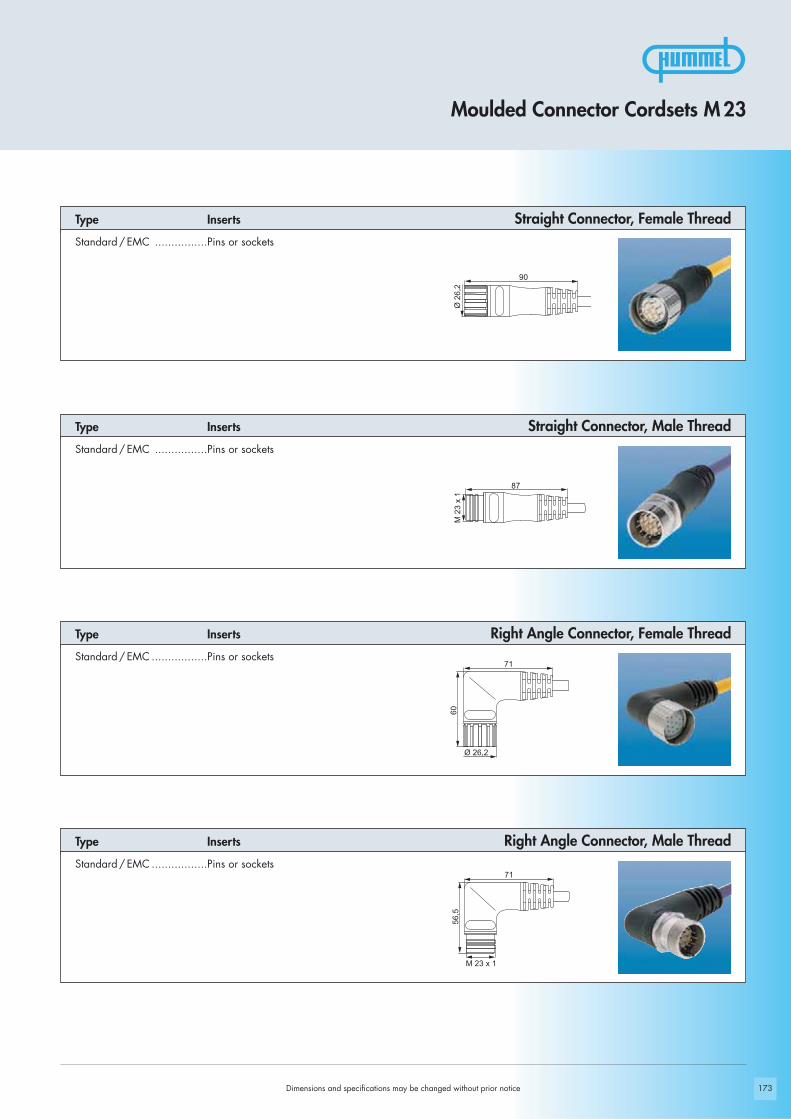
87
M 2
3 x
1Ø
26,
2
90
71
60
Ø 26,2
71
56,5
M 23 x 1
173Dimensions and specifications may be changed without prior notice
Moulded Connector Cordsets M 23
Type Inserts
Standard / EMC ................Pins or sockets
Straight Connector, Female Thread
Type Inserts Straight Connector, Male ThreadStandard / EMC ................Pins or sockets
Type Inserts Right Angle Connector, Female ThreadStandard / EMC .................Pins or sockets
Right Angle Connector, Male ThreadType Inserts
Standard / EMC .................Pins or sockets

Ø 2
6,2
90
87
M 2
3 x
1
71
60
Ø 26,2
71
56,5
M 23 x 1
174 Dimensions and specifications may be changed without prior notice
Right Angle Connector, Male ThreadStandard / EMC ................Pins or sockets
Type Inserts
Standard / EMC ................Pins or sockets
Type InsertsRight Angle Connector, Female Thread
Straight Connector, Male ThreadStandard / EMC ................Pins or sockets
Type Inserts
Standard / EMC .................Pins or sockets
Type InsertsStraight Connector, Female Thread
Moulded Connector Cordsets M 23
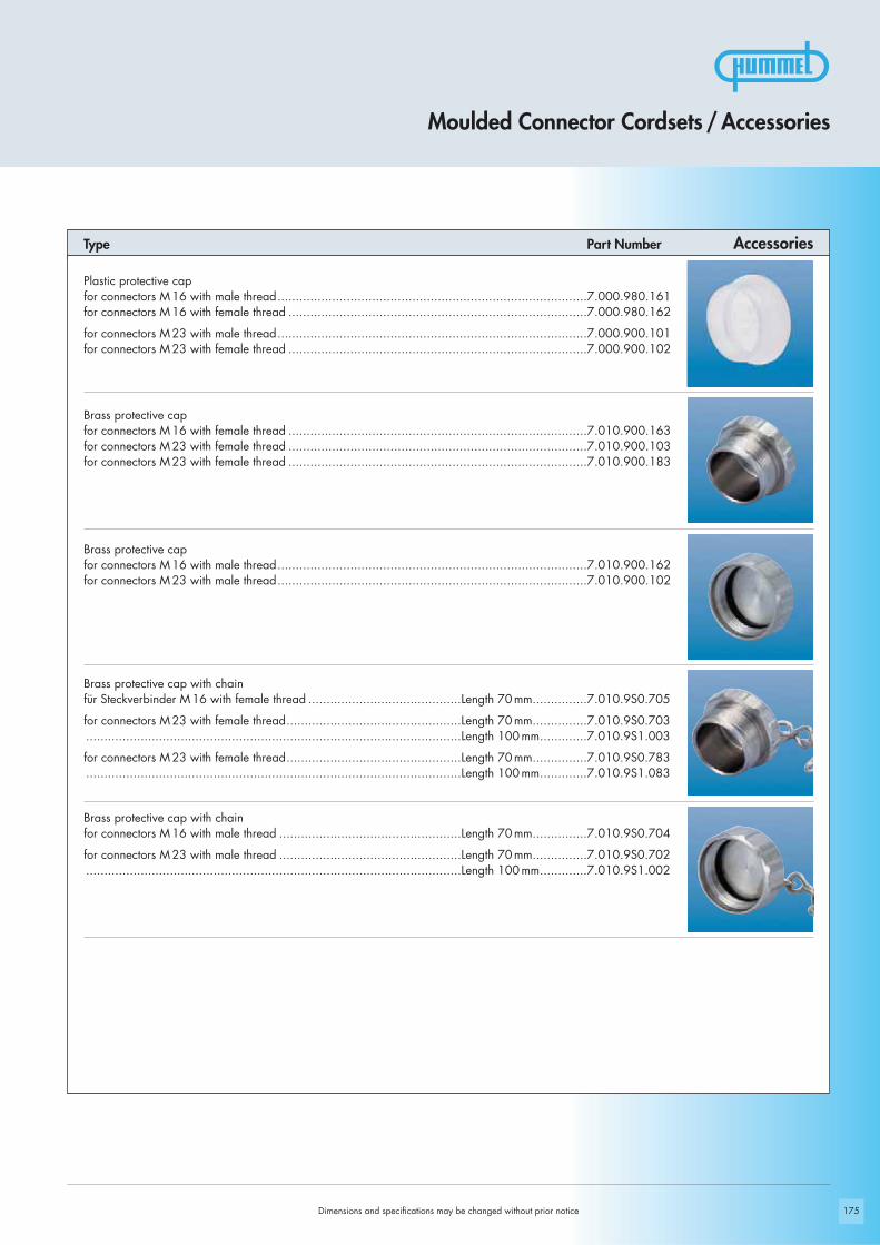
175Dimensions and specifications may be changed without prior notice
AccessoriesType Part Number
Moulded Connector Cordsets / Accessories
Plastic protective capfor connectors M 16 with male thread.....................................................................................7.000.980.161for connectors M 16 with female thread ..................................................................................7.000.980.162
for connectors M 23 with male thread.....................................................................................7.000.900.101for connectors M 23 with female thread ..................................................................................7.000.900.102
Brass protective cap for connectors M 16 with female thread ..................................................................................7.010.900.163for connectors M 23 with female thread ..................................................................................7.010.900.103for connectors M 23 with female thread ..................................................................................7.010.900.183
Brass protective cap for connectors M 16 with male thread.....................................................................................7.010.900.162for connectors M 23 with male thread.....................................................................................7.010.900.102
Brass protective cap with chain für Steckverbinder M 16 with female thread ..........................................Length 70 mm...............7.010.9S0.705
for connectors M 23 with female thread................................................Length 70 mm...............7.010.9S0.703.......................................................................................................Length 100 mm.............7.010.9S1.003
for connectors M 23 with female thread................................................Length 70 mm...............7.010.9S0.783.......................................................................................................Length 100 mm.............7.010.9S1.083
Brass protective cap with chain for connectors M 16 with male thread ..................................................Length 70 mm...............7.010.9S0.704
for connectors M 23 with male thread ..................................................Length 70 mm...............7.010.9S0.702.......................................................................................................Length 100 mm.............7.010.9S1.002

176
IP 67 – liquid tight when disconnected
Using a rubber diaphragm makes this connector liquid tighteither connected or disconnected (NEMA 4 = IP 67).
Bulkhead Connector
Bulkhead connectors accept plugs on both sides. They arerugged, liquid tight and available in all number of poles.
Simple EMI / RFI shielding
An integrated metalized EMI clamping insert grounds to thebraid signifficantly simplifying the assembly of the elbow connector.
MULTI Seal Connector
A large selection of standard MULTI seal inserts allow strainrelief of several individual conductors on one single connector.
No Limits
Dimensions and specifications may be changed without prior notice

177
Flexible Cable Protection
In addition to the integrated strain relief, the flex nut adds kinkprotection to a cable - available for all connector sizes.
Adaptor flange
To secure loose connections, an adaptor flange can be attached to a straight connector.
12-point hex and knurled nut
This special nut makes connection simple by eighter tighteningthe connector manually (knurled nut) or with a wrench (12-point hex).
Conduit Attachment
Flexible corrugated conduit can be attached to a connectorwith an adapter offering strain relief and cable protection aswell.
No Limits
Dimensions and specifications may be changed without prior notice

178
Connector with specific pull-out resistance Bulkhead Fitting
Captive Protective Cap ANACONDA Conduit Adapter
Dimensions and specifications may be changed without prior notice
After reaching a certain pull-out force the connection releases preventing damage to the device (apparatus).
This fitting with oversized flange is commonly used in the shipbuilding industry where Signal Connections have to be main-tained under extreme conditions.
The metal protective cap is secured to a cable by a safetyring and stays attached in open connections.
HUMMEL offers custom adapters for ANACONDA conduitsystems in hazardous locations.
No Limits

179
No Limits
Distibution-box Coloured Overmould
Distribution-boxes are known as important components forapplications in automation. Robust and fully wired they aredone according to customers specification.
Completing a design or showing technical functions, over-mould could be made in different colours too (e.g. DESINAgreen RAL 6018).
Dimensions and specifications may be changed without prior notice
High temperature applications
For high temperature applications HUMMEL offers connectorswith special inserts able to stand temperatures up to 160 °C(320 °F).
Hybrid Connector for Compressed Air
To place lines for compressed air and electrical signals in onesingle connection, a hybrid connector M 23 combines differenttypes of contacts in one insert.

20 30 40 50 100 110 120 T [°C]60 70 80 90
I [A]
0
1
2
3
4
5
6
7
8
9
20 30 40 50 100 110 120 T [C]60 70 80 90
I [A]
0
2
4
6
8
10
12
14
16
18
20 30 40 50 100 110 120 T [°C]60 70 80 900
1
2
3
4
5
6
7
8
9
I [A]
180
Derating M 16
Straight connectors male + female, 10 pole,
wires 10 x AWG18
Derating M 16 TWINTUS
Derating M 23 Signal
TWINTUS and straight connector female M 16
4+3+PE, wires AWG 14 (Power)
10pole, wires AWG 26
Straight Connectors male + female,
wires 12 x AWG17
Dimensions and specifications may be changed without prior notice
Derating

20 30 40 50 100 110 120 T [°C]60 70 80 90
I [A]
0
5
10
15
20
25
30
20 30 40 50 100 110 120 T [°C]60 70 80 90
I [A]
0
10
20
30
40
50
60
181
Straight connectors male + female M 23, 5 + PE,
wires 5 x AWG12
Derating M 40 (Size 1,5)
Derating M 23 Power
Straight connectors male + female,
wires 3 x AWG 6
Dimensions and specifications may be changed without prior notice
Derating
182 Dimensions and specifications may be changed without prior notice
Created and printed byGraphic & Layout: intermedia marketing gmbh, Mozartstraße 2, 79183 Waldkirch, Germany, Tel. +49 (0) 76 81/ 47 78 99-0, Fax +49 (0) 76 81/ 47 78 99-27, [email protected]: Druckerei Furtwängler GmbH, 79211 Denzlingen, Germany, Tel. +49 (0) 76 66 /13 31. Printed on recycled paper in March 2012. English 2012
Limited LiabilityProducts, design, colors and dimensions are subject to change without prior notice. We reserve the right to make technical improvements on all our products, currently ordered or for futureorders. It is the users responsibility to verify all dimensions and technical data. HUMMEL AG will assume no liability regarding information provided to the user by published literature orinside technical staff, its distributors and outside sales personnel. Errors in the catalog can occur and shall not create any liability whatsoever for HUMMEL. All information provided by HUMMEL is without guarantee and must be verified by the user.
Page Finder
Page FinderPart Number Page Part Number Page Part Number Page Part Number Page
7.000.848.101 . . . . . . . .307.000.848.102 . . . . . . . .307.000.900.101 . . . . . . . . . .
. . .51, 59, 82, 116, 1657.000.900.102 . . . . . . . . . .
. . .51, 59, 82, 116, 1657.000.900.151 . . . . . . .1387.000.900.152 . . . . . . .1387.000.900.901 . . . . . . . . . .
. . . . . . . .101, 117, 1657.000.900.902 . . . . . . .1397.000.900.903 . . . . . . .1397.000.900.904 . . . . .30, 837.000.900.906 . . . . . . . .527.000.900.907 . . . . . . . .527.000.980.16 . . . . . . . . .297.000.980.167 . . . . . . .1017.000.980.168 . . . . . . .1017.000.9DM.C03 . . . . . . .837.000.9DM.C04 . . . . . . .837.000.9DM.C06 . . . . . .1177.000.9DM.C07 . . . . . .1177.001.903 . . . . . . . . . . . .227.001.906 . . . . . . . . . . . .747.001.907 . . . . . . . . . . . .747.001.908 . . . . . . . . . . . .237.001.910 . . . . . . . . . . . .247.001.912 . . . . . . . . . . . .767.001.916 . . . . . . . . . . . .777.001.917 . . . . . . . . . . . .777.001.919 . . . . . . . . . . . .787.001.920 . . . . . . . . . . . .467.001.926 . . . . . . . . . . . .997.001.928 . . . . . . . . . . . .997.001.943 . . . . . . . . . . . .237.001.981 . . . . . . . . . . . .757.001.983 . . . . . . . . . . . .227.001.985 . . . . . . . . . . . .247.001.988 . . . . . . . . . . . .257.002.912 . . . . . . . . . . . .767.002.917 . . . . . . . . . . . .787.002.981 . . . . . . . . . . . .757.003.903 . . . . . . . . . . . .227.003.906 . . . . . . . . . . . .747.003.907 . . . . . . . . . . . .747.003.908 . . . . . . . . . . . .237.003.910 . . . . . . . . . . . .247.003.912 . . . . . . . . . . . .767.003.916 . . . . . . . . . . . .777.003.917 . . . . . . . . . . . .777.003.919 . . . . . . . . . . . .787.003.920 . . . . . . . . . . . .467.003.926 . . . . . . . . . . . .997.003.943 . . . . . . . . . . . .237.003.981 . . . . . . . . . . . .757.003.983 . . . . . . . . . . . .227.003.985 . . . . . . . . . . . .247.003.988 . . . . . . . . . . . .257.004.912 . . . . . . . . . . . .767.004.917 . . . . . . . . . . . .787.004.981 . . . . . . . . . . . .757.010.900.101 . . . . . . . .827.010.900.102 . . . . . . . . . . . .
. . . . . . . . .51, 59, 82, 1167.010.900.103 . . . . . . . .827.010.900.110 . . . . . . .1017.010.900.125 . . . . . . . .297.010.900.127 . . . . . . .1657.010.900.128 . . . . . . . . . .
. . . . . . . . . .59, 83, 117
7.010.900.129 . . . . . . .1397.010.900.135 . . . . . . . .307.010.900.139 . . . . . . . .527.010.900.14 . . . . . . . . .537.010.900.162 . . . . . . . .297.010.900.163 . . . . . . . .297.000.980.167 . . . . . . .1017.000.980.168 . . . . . . .1017.010.900.170 . . . . . . .1017.010.900.183 . . . . . . . .517.010.900.200 . . . . . . . .307.010.900.201 . . . . . . . .307.010.900.202 . . . . . . . .307.010.900.203 . . . . . . . .307.010.900.204 . . . . . . . . . .
. . . . . . .51, 60, 83, 1177.010.900.205 . . . . . . . . . .
. . . . . . .51, 60, 83, 1177.010.900.206 . . . . . . . . . .
. . . . . . .51, 60, 83, 1177.010.900.207 . . . . . . . . . .
. . . . . . .51, 60, 83, 1177.010.900.208 . . . . . . . . . .
. . . . . . .51, 60, 83, 1177.010.900.209 . . . . . . . . . .
. . . . . . .51, 60, 83, 1177.010.900.214 . . . . . . .1397.010.900.215 . . . . . . .1397.010.900.216 . . . . . . .1397.010.900.217 . . . . . . .1397.010.900.129 . . . . . . .1397.010.901.001 . . . . .26, 807.010.901.002 . .26, 46, 807.010.901.012 . .27, 46, 807.010.901.021 . . . . . . . .807.010.901.022 . . . . .46, 807.010.901.031 . . . . . . . .807.010.901.5 . . . . . . .80, 817.010.902.0 . . . . . . . . . .817.010.904.102 . . . . . . .1657.010.904.103 . . . . . . .1657.010.94 . . . . . . . . . . . .1157.010.950.102 . . . . . . .1547.010.955.102 . . . . . . .1547.010.971 . . . . . . . . . . .1007.010.980.6 . . . . . . .46, 477.010.980.8 . . . .23, 26, 277.010.981 . . . . . . . . .23, 277.010.982 . . . . . . . . . . . .287.010.9S0.702 . . . . . . . . . .
. . . . . . .51, 59, 82, 1167.010.9S0.703 . . . . . . . .827.010.9S0.704 . . . . . . . .297.010.9S0.705 . . . . . . . .297.010.9S0.707 . . . . . . .1017.010.9S0.708 . . . . . . .1017.010.9S0.783 . . . . . . . .517.010.9S1.002 . . . . . . . . . .
. . . . . . .51, 59, 82, 1167.010.9S1.003 . . . . . . . .827.010.9S1.083 . . . . . . . .517.010.9S4.102 . . . . . . .1657.010.9S4.103 . . . . . . .1657.015.95 . . . . . . . .136, 1377.015.900.102 . . . . . . .1387.015.900.103 . . . . . . .1387.015.9S1.002 . . . . . . .1387.015.9S1.003 . . . . . . .1387.053.9 . . . . . . . . . . . . . .237.084.943 . . . . . . . . . . .114
7.084.951 . . . . . . . . . . .1147.106 . . . . . . . . . . . . . . .667.108 . . . . . . . . . . . . . . .447.110 . . . . . . . . . . . . . . .987.105 . . . . . . . . . . . . . . .737.140 . . . . . . . . . . . . . .1627.141 . . . . . . . . . . . . . .1627.156 . . . . . . . . . . . . . .1537.206 . . . . . . . . . . . . . . .667.208 . . . . . . . . . . . . . . .447.210 . . . . . . . . . . . . . . .987.240 . . . . . . . . . . . . . .1627.241 . . . . . . . . . . . . . .1627.300 . . . . . . . . . . . . . . .677.301 . . . . . . . . . . . . . . .677.304 . . . . . . . . . . . . . .1537.305 . . . . . . . . . . . . . .1537.306 . . . . . . . . . . . . . . .677.308 . . . . . . . . . . . . . . .447.350 . . . . . . . . . . . . . . .677.400 . . . . . . . . . . . . . . .687.402 . . . . . . . . . . . . . . .687.404 . . . . . . . . . . . . . . .687.406 . . . . . . . . . . . . . . .687.408 . . . . . . . . . . . . . . .447.410.0 . . . . . . . . . . . . . .687.410.4 . . . . . . . . . . . . .1637.410.7 . . . . . . . . . . . . . .987.412 . . . . . . . . . . . . . . .687.414 . . . . . . . . . . . . . . .687.416 . . . . . . . . . . . . . . .687.420 . . . . . . . . . . . . . . .697.421 . . . . . . . . . . . . . . .697.422 . . . . . . . . . . . . . . .697.423 . . . . . . . . . . . . . . .697.425 . . . . . . . . . . . . . . .697.430.4 . . . . . . . . . . . . .1637.431 . . . . . . . . . . . . . . .707.432 . . . . . . . . . . . . . . .707.433 . . . . . . . . . . . . . . .707.433.1 . . . . . . . . . . . . . .707.435 . . . . . . . . . . . . . . .707.440.0 . . . . . . . . . . . . . .687.440.5 . . . . . . . . . . . . .1547.444 . . . . . . . . . . . . . . .687.448.0 . . . . . . . . . . . . . .687.448.5 . . . . . . . . . . . . .1547.449 . . . . . . . . . . . . . . .687.450 . . . . . . . . . . . . . . .717.452 . . . . . . . . . . . . . . .717.454 . . . . . . . . . . . . . . .717.456 . . . . . . . . . . . . . . .717.458 . . . . . . . . . . . . . . .717.459 . . . . . . . . . . . . . . .717.460 . . . . . . . . . . . . . . .717.462 . . . . . . . . . . . . . . .717.464 . . . . . . . . . . . . . . .717.466 . . . . . . . . . . . . . . .717.468 . . . . . . . . . . . . . . .457.476 . . . . . . . . . . . . . . .667.486 . . . . . . . . . . . . . . .667.490 . . . . . . . . . . . . . . .727.491 . . . . . . . . . . . . . . .727.492 . . . . . . . . . . . . . . .727.550 . . . . . . . . . . . . . .1087.554 . . . . . . . . . . . . . .1647.555 . . . . . . . . . . . . . .1557.559 . . . . . . . . . . . . . .1087.560 . . . . . . . . . . . . . .1087.564 . . . . . . . . . . . . . .164
7.569 . . . . . . . . . . . . . .1087.575 . . . . . . . . . . . . . .1557.576 . . . . . . . . . . . . . .1097.579 . . . . . . . . . . . . . .1097.580 . . . . . . . . . . . . . .1097.589 . . . . . . . . . . . . . .1097.601 . . . . . . . . . . . . . .1107.601.4 . . . . . . . . . . . . .1647.605 . . . . . . . . . . . . . .1107.621 . . . . . . . . . . . . . .1117.623 . . . . . . . . . . . . . .1117.626 . . . . . . . . . . . . . .1117.630.4 . . . . . . . . . . . . .1647.635 . . . . . . . . . . . . . .1127.636 . . . . . . . . . . . . . .1127.637 . . . . . . . . . . . . . .1127.638 . . . . . . . . . . . . . .1127.638.1 . . . . . . . . . . . . .1127.641 . . . . . . . . . . . . . .1107.645 . . . . . . . . . . . . . .1107.651 . . . . . . . . . . . . . .1117.653 . . . . . . . . . . . . . .1137.661 . . . . . . . . . . . . . .1137.681 . . . . . . . . . . . . . .1137.683 . . . . . . . . . . . . . .1137.710 . . . . . . . . . . . . . .1327.715 . . . . . . . . . . . . . .1567.720 . . . . . . . . . . . . . .1327.725 . . . . . . . . . . . . . .1577.740.0 . . . . . . . . . . . . .1337.740.5 . . . . . . . . . . . . .1587.742 . . . . . . . . . . . . . .1347.743 . . . . . . . . . . . . . .1347.744 . . . . . . . . . . . . . .1337.810 . . . . . . . . . . . . . . .187.813 . . . . . . . . . . . . . .1527.820 . . . . . . . . . . . . . . .187.823 . . . . . . . . . . . . . .1527.830 . . . . . . . . . . . . . . .187.831 . . . . . . . . . . . . . . .187.840 . . . . . . . . . . . . . . .197.840.3 . . . . . . . . . . . . .1527.842 . . . . . . . . . . . . . . .207.843 . . . . . . . . . . . . . . .207.845 . . . . . . . . . . . . . . .207.847 . . . . . . . . . . . . . . .197.848 . . . . . . . . . . . . . . .217.850.0 . . . . . . . . . . . . . .207.850.3 . . . . . . . . . . . . .1527.852 . . . . . . . . . . . . . . .197.R10.4 . . . . . . . . . . . . . .567.R20.4 . . . . . . . . . . . . . .567.R40.0 . . . . . . . . . . . . . .567.R41.0 . . . . . . . . . . . . . .567.R42.0 . . . . . . . . . . . . . .577.R50.0 . . . . . . . . . . . . . .577.R43.0 . . . . . . . . . . . . . .577.R45.0 . . . . . . . . . . . . . .577.R52.4 . . . . . . . . . . . . . .587.R47.4 . . . . . . . . . . . . . .587.T01 . . . . . . . . . . . . . . .737.T02 . . . . . . . . . . . . . . .73

183
HUMMEL International
HUMMEL Brazil
HUMMEL Connector Systems Ltda.Rua Derville Gabriel Pereira, 280Barro Preto - Centro Empresarial Tatuí I CEP 18280-614 - Tatuí/SP/Brazil
Tel. +55 (15)3322-7000Fax +55(15) 3322-7026E-Mail [email protected]
HUMMEL China
HUMMEL Connector Systems (Shanghai) Co., Ltd.Room 1701 Central PlazaNo.227 Huang Pi (N) Road200003 Shanghai / P.R. China
Tel. +86 / 21 63 75 85-51Fax +86 / 21 63 75 85-53E-Mail [email protected]
HUMMEL France
HUMMEL s.a.r.l.4, rue des fleurs68190 Ungersheim /France
Tel. +33 (0) 3 89 / 55 37 20Fax +33 (0) 3 89 / 53 80 27 E-Mail [email protected]
HUMMEL UK
HUMMEL UK LimitedOffice 3, Momentum HouseEnterprise Way, Lowton St Marys, Warrington, Cheshire, WA3 2BPUnited Kingdom
Tel. +44 (0)1942/605695Fax +44 (0)1942/269324E-Mail [email protected]
HUMMEL India
HUMMEL Connector Systems Pvt. Ltd.1211, Surya Kiran Building, 19, Kasturba Gandhi Marg110001 New Delhi/India
Tel. +91/11/ 430075-21/- 23Fax +91/11/430075-22E-Mail [email protected]
HUMMEL Italy
HUMMEL s.r.l.Via Valdellatorre 18210091 Alpignano (Torino)/ Italy
Tel. +39 / (0 )11 / 9 68 26 38 Fax +39 / (0) 11 / 9 78 55 50E-Mail [email protected]
HUMMEL Kazakhstan
HUMMEL Sales Office KasachstanTurksibskij rayon, Mikrorayon Zhuldyz-1, dom 6, kwartira 19050049 Almaty/Kasachstan
Tel. +7 701 7262004E-Mail [email protected]
HUMMEL Poland
HUMMEL Sales Office PolandAl. 23 Stycznia 26 lok. 2086-300 Grudziadz/Polen
Tel. +48 (0) 662382799Fax +48 (0) 566430011E-Mail [email protected]
HUMMEL Russia
OOO HUMMELRetschnikow 21, Strojenije 1 115142 Moskau/Russia
Tel. +7 / 499 / 7 82 - 40 75Fax +7 / 499 / 6 14 - 67 40E-Mail [email protected]
HUMMEL Scandinavia
HUMMEL Connector Systems ABFörsta Magasinsgatan 580310 Gävle / Sweden
Tel. +46/73 8001200Fax +46/26 143873E-Mail [email protected]
HUMMEL Hungary
HUMMEL Ungarn Kft.Ko’rösi út 49.2360 Gyál / Hungary
Tel. +36 / 29 54 06 33Fax +36 / 29 54 06 35E-Mail [email protected]

inte
rmed
ia 0
112
www.hummel.com
HUMMEL Divisions
Touchsensors – Touchpanels – Touchsystems
ElectronicOperator Panels – Frontsheets and KeyboardsCustom fabrication of Enclosures – Battery Chargers – Cable AssemblySensors – Controls – Systems Solutions – Temperature Controllers
Industrial Enclosures – Cable GlandsCable Protection – Circular Connectors
Valves and Fittings – Compression Fittings Heat Pumps – Thermostatic Heads
Parts made of Metal and Nylon
Electro Technology
Heating Equipment
Customized
Touch
Tel. +49 (0)76 66/91110-0Fax +49 (0)76 66/91110-20E-Mail [email protected]
HUMMEL AGLise-Meitner-Straße 279211 DenzlingenGermanywww.hummel.com
HUMMEL AGDivision ETLise-Meitner-Straße 279211 DenzlingenGermany