K-space polarimetry of bullseye plasmon · PDF...
7
K-space polarimetry of bullseye plasmon antennas Clara I. Osorio, Abbas Mohtashami & A. Femius Koenderink Center for Nanophotonics, FOM Institute AMOLF, Science Park 104, 1098 XG Amsterdam, The Netherlands. Surface plasmon resonators can drastically redistribute incident light over different output wave vectors and polarizations. This can lead for instance to sub-diffraction sized nanoapertures in metal films that beam and to nanoparticle antennas that enable efficient conversion of photons between spatial modes, or helicity channels. We present a polarimetric Fourier microscope as a new experimental tool to completely characterize the angle-dependent polarization-resolved scattering of single nanostructures. Polarimetry allows determining the full Stokes parameters from just six Fourier images. The degree of polarization and the polarization ellipse are measured for each scattering direction collected by a high NA objective. We showcase the method on plasmonic bullseye antennas in a metal film, which are known to beam light efficiently. We find rich results for the polarization state of the beamed light, including complete conversion of input polarization from linear to circular and from one helicity to another. In addition to uncovering new physics for plasmonic groove antennas, the described technique projects to have a large impact in nanophotonics, in particular towards the investigation of a broad range of phenomena ranging from photon spin Hall effects, polarization to orbital angular momentum transfer and design of plasmon antennas. A n ultimate goal of nanophotonics is to engineer single nanostructures, or clusters of them, capable of precisely manipulating the propagation, emission and absorption of light. A large interest in this cap- ability stems on one hand from projected applications of plasmonics 1 and metamaterials 2,3 in domains ranging from improved photovoltaics 4 , efficient solid-state lighting 5 and on-chip optical components 1 to the improvement of research tools in spectroscopy and microscopy at the single molecule level 6 . On the other hand, the fields of plasmonics, metamaterials, and metasurfaces 1–3 continue to surprise both with new insights in the peculiar solutions of Maxwell’s equations when exotic material responses are introduced, and in the parallels with solid-state phenomena such as the spin hall effect 7–12 or topological insulator physics 13 . The behavior of any single nanostructure in response to an incident optical wave is most generally described by a so-called t-matrix 14–16 , also known as scattering matrix or generalized transmission function. In the case of scattering, the t-matrix completely specifies the far-field distribution for any incident field, including polarization, amplitude, phase, and k-distribution of both fields 14–16 . Experimental techniques for the characterization of nanostructures, such as bright and dark field microscopy or NSOM, measure different subsets of the transmission function. However, there is no single technique that can map the complete transformation of incident light into the far field. This paper introduces high-NA k-space polarimetry 17–20 as a technique to measure the response of single scatterers to incident fields with different polarizations. This technique combines a Fourier microscope 21,22 , capable of mapping the k-vector distribution of scattered radiation, with a polarimeter 23–25 that measures the full polarization state for each wave vector. For a given incident k-vector distribution, a k-space polarimeter measures all information encoded in the transmission function of a scatterer across an entire microscope back aperture, up to an over-all phase. In order to demonstrate k-space polarimetry we consider bullseye antenna scatterers (BEs), consisting of periodic grooves concentric to a circular hole in a plasmonic metal film, Fig. 1 (a). These antennas are among the simplest, most widely used, and best understood plasmonic structures that scatter light directionally 26–29 . Furthermore, bullseye antennas are widely studied for their ability to impart directionality to the fluorescence of fluorophores residing in the central aperture 30 . While the role of wavelength and antenna design on field enhancement and directionality is well understood 31 , the polarization state of the light scattered by BEs has been only partially characterized 32–35 . Here we use k-space polarimetry to measure the angle-resolved polarization state of the scattering of bullseyes under different illuminations. Our results show strong linear-to-circular polarization conversion at off-normal scattered wave vectors, showing that even a structure as ubiquitous as a bullseye antenna still contains surprising physics, relating to the emerging field of controlling spin-orbit coupling for photons 7–12 . OPEN SUBJECT AREAS: IMAGING TECHNIQUES MICROSCOPY POLARIZATION MICROSCOPY Received 11 January 2015 Accepted 25 March 2015 Published Correspondence and requests for materials should be addressed to A.F.K. (f.koenderink@ amolf.nl) SCIENTIFIC REPORTS | 5 : 9966 | DOI: 10.1038/srep09966 1 30 April 2015
Transcript of K-space polarimetry of bullseye plasmon · PDF...

K-space polarimetry of bullseye plasmonantennasClara I. Osorio, Abbas Mohtashami & A. Femius Koenderink
Center for Nanophotonics, FOM Institute AMOLF, Science Park 104, 1098 XG Amsterdam, The Netherlands.
Surface plasmon resonators can drastically redistribute incident light over different output wave vectors andpolarizations. This can lead for instance to sub-diffraction sized nanoapertures inmetal films that beam andto nanoparticle antennas that enable efficient conversion of photons between spatial modes, or helicitychannels. We present a polarimetric Fourier microscope as a new experimental tool to completelycharacterize the angle-dependent polarization-resolved scattering of single nanostructures. Polarimetryallows determining the full Stokes parameters from just six Fourier images. The degree of polarization andthe polarization ellipse are measured for each scattering direction collected by a high NA objective. Weshowcase the method on plasmonic bullseye antennas in a metal film, which are known to beam lightefficiently.We find rich results for the polarization state of the beamed light, including complete conversionof input polarization from linear to circular and from one helicity to another. In addition to uncovering newphysics for plasmonic groove antennas, the described technique projects to have a large impact innanophotonics, in particular towards the investigation of a broad range of phenomena ranging from photonspin Hall effects, polarization to orbital angular momentum transfer and design of plasmon antennas.
A n ultimate goal of nanophotonics is to engineer single nanostructures, or clusters of them, capable ofprecisely manipulating the propagation, emission and absorption of light. A large interest in this cap-ability stems on one hand from projected applications of plasmonics1 and metamaterials2,3 in domains
ranging from improved photovoltaics4, efficient solid-state lighting5 and on-chip optical components1 to theimprovement of research tools in spectroscopy and microscopy at the single molecule level6. On the other hand,the fields of plasmonics, metamaterials, and metasurfaces1–3 continue to surprise both with new insights in thepeculiar solutions ofMaxwell’s equations when exoticmaterial responses are introduced, and in the parallels withsolid-state phenomena such as the spin hall effect7–12 or topological insulator physics13.
The behavior of any single nanostructure in response to an incident optical wave is most generally described bya so-called t-matrix14–16, also known as scattering matrix or generalized transmission function. In the case ofscattering, the t-matrix completely specifies the far-field distribution for any incident field, including polarization,amplitude, phase, and k-distribution of both fields14–16. Experimental techniques for the characterization ofnanostructures, such as bright and dark fieldmicroscopy orNSOM,measure different subsets of the transmissionfunction. However, there is no single technique that can map the complete transformation of incident light intothe far field.
This paper introduces high-NA k-space polarimetry17–20 as a technique to measure the response of singlescatterers to incident fields with different polarizations. This technique combines a Fourier microscope21,22,capable of mapping the k-vector distribution of scattered radiation, with a polarimeter23–25 that measures thefull polarization state for each wave vector. For a given incident k-vector distribution, a k-space polarimetermeasures all information encoded in the transmission function of a scatterer across an entire microscope backaperture, up to an over-all phase.
In order to demonstrate k-space polarimetry we consider bullseye antenna scatterers (BEs), consisting ofperiodic grooves concentric to a circular hole in a plasmonic metal film, Fig. 1 (a). These antennas are amongthe simplest, most widely used, and best understood plasmonic structures that scatter light directionally26–29.Furthermore, bullseye antennas are widely studied for their ability to impart directionality to the fluorescence offluorophores residing in the central aperture30. While the role of wavelength and antenna design on fieldenhancement and directionality is well understood31, the polarization state of the light scattered by BEs has beenonly partially characterized32–35. Here we use k-space polarimetry tomeasure the angle-resolved polarization stateof the scattering of bullseyes under different illuminations. Our results show strong linear-to-circular polarizationconversion at off-normal scattered wave vectors, showing that even a structure as ubiquitous as a bullseye antennastill contains surprising physics, relating to the emerging field of controlling spin-orbit coupling for photons7–12.
OPEN
SUBJECT AREAS:
IMAGING TECHNIQUES
MICROSCOPY
POLARIZATION MICROSCOPY
Received11 January 2015
Accepted25 March 2015
Published
Correspondence andrequests for materials
should be addressed toA.F.K. (f.koenderink@
amolf.nl)
SCIENTIFIC REPORTS | 5 : 9966 | DOI: 10.1038/srep09966 1
30 April 2015

K-space polarimetryAt the basis of our k-space polarimeter is a conventional microscope,with a ‘‘Bertrand’’ or ‘‘Fourier’’ lens. A Fourier microscope exploitsthe fact that the back focal plane of a microscope objective providesaccess to the entire distribution of k-vectors collected by it, which canbe directly mapped onto a CCD camera chip. Fourier imaging hasbeen applied, for instance, to image the radiation pattern of singleemitters to determine their dipole moment21,22 and to map the direc-tivity optical antennas impart to emitters30,36–38. Fourier microscopeshave been also used in scattering experiments on single nano-structures39 and nanostructure arrays40–43. The back focal plane ina Fourier microscope retains full information regarding momentum,but also in other degrees of freedom such as energy (frequency) andpolarization. Accessing this information requires additional analy-zers. For instance, energy resolved radiation patterns have beenmea-sured using spectrometers44 or gratings45 to disperse Fourier images.Regarding polarization, Fourier microscopy measurements have
been reported with a single linear polarizer as analyzer39,46, whichonly partially interrogates the polarization state of the scattered field.Given the nature of polarization, it is fundamentally impossible toretrieve the full state from linear-polarization measurements.Moreover, the very strong refraction of rays in high NA aplanaticlenses means that imaging through linear analyzers behind themicroscope objective does not correspond to a natural polarizationbasis. Indeed, in the beam behind the objective, the basis of s and p-polarization applicable to the spherical wave emanating into the farfield from a scatterer in the object plane converts to radial and azi-muthal polarization, and not into orthogonal Cartesian polariza-tions. Thereby a simple linear polarization analysis is incomplete,and impractical.Polarimeters perform complete polarization measurement, that is
measurements that allow retrieving the Stokes parameters S0, S1, S2and S3 In this work we place a polarimeter in a Fouriermicroscope, todetermine the polarization state for each scattered k-vector.We use arotating-plate polarimeter composed by a quarter wave plate (QWP)followed by a linear polarizer (LP)23–25. These two elements act as alinear polarizer when their optical axes are aligned and as a circularpolarizer when the angle between their optical axes is p/4. If Ia,b is theintensity measured after rotating the QWP by an angle a and the LPby an angle b (subscript labels expressed in degrees) with respect tothe x axis, the Stokes parameters are given by
S0~I0,0zI90,90
S1~I0,0{I90,90
S2~I45,45{I135,135
S3~I0,45{I0,135:
ð1Þ
Thus a total of six measurements are used to retrieve the fourStokes parameters. The first Stokes parameter, S0, corresponds tototal intensity. The other three parameters are given by the differencebetween intensities transmitted by orthogonally orientated polari-zers: horizontal and vertical for S1, diagonal plus and minus for S2,and right and left-handed circular for S3.Since the Stokes parameters fully describe polarization, any other
figure of merit for polarization can be retrieved from them. Forinstance, the total degree of polarizationDP and the degrees of linearDLP and circular polarization DCP are given by
DP~
ffiffiffiffiffiffiffiffiffiffiffiffiffiffiffiffiffiffiffiffiffiffiS21zS22zS23
pS0
DLP~
ffiffiffiffiffiffiffiffiffiffiffiffiffiS21zS22
pS0
DCP~jS3jS0
:
ð2Þ
This capability of a polarimeter to determine howmuch of a beamis actually polarized would be especially useful in plasmon-enhancedfluorescence experiments, where coupling to a plasmon resonancemay impart polarization even to randomly oriented dipole emitters.Other intuitive, and commonly used, figures ofmerit for polarizationthat are easily obtained from the Stokes parameters include theamount of s- and p-polarized light, or the ellipticity and orientationof the polarization ellipse.
Experimental setupFigure 2 shows our setup with its two main components: a home-built Fourier microscope (b) and a rotating-plate polarimeter (c). Asa light source, we use a supercontinuum laser (Fianium) filtered by anacousto-optical tunable filter (AOTF) and a 20 nm band pass filtercentered at 750 nm. A linear polarizer and a quarter wave plate setthe input beam polarization, Fig. 2(a). A 10 3 objective weaklyfocuses the light on the sample and a 60 3 objective (NA 5 0.7)collects the resulting radiation. The presented technique is not lim-ited to these choices: both illumination and detection sides canencompass any available objective NA. Moreover, a full polarimetrick-vector mapping on the incident side is possible by scanning amildly focused input beam in the back focal plane of the inputobjective47 On the collection side, light passes through a spatial filterin an intermediate image plane to isolate light scattered only by asingle nanostructure. The spatial filter is composed of a 151 telescope(2ftelescope 5 100 mm) and a 300 mm pinhole, equivalent to about20 mm on the sample. To obtain Fourier images, i.e., to image theback focal plane of the objective onto a CCD camera (PhotometricsCoolSnap EZ), we use a fFourier 5 200 mm lens placed at a distance4ftelescope 1 fFourier from the back focal plane, followed by a ftube 5200 mm tube lens. The rotating-plate polarimeter consists of abroadband quarter wave plate (Thorlabs AQWP-600) and a linearpolarizer (Thorlabs LPVIS100), and it is placed just before the tubelens.Our sample was fabricated in a 200 nm thick gold film evaporated
on a glass cover slip that was first coated with a 5 nm chromiumadhesion layer. The bullseye antennas were imprinted on the filmwith a focused ion beam (FIB) by milling isolated circular holes witha diameter of 210 nm through the metal and engraving 8 grooves ofabout 60 nm depth that are concentric with the holes. We studiedstructures with different distances between consecutive grooves(pitch p) and between the central hole and the first groove (d).We present results for two structures BE440 with p 5 440 nmand d 5 330 nm, shown in Fig. 1(a) and BE600 with p 5 600 nmand d 5 600 nm. In all cases the width of each groove was half thepitch. In our experiments the structure is immersed in water, so as to
Figure 1 | We study the polarization properties of the scattering ofbullseye antennas. (a) Shows a scanning electron micrograph of 440 nm
pitch antenna. (b) The spherical wave emanating into the far field from a
scatterer in the object plane, naturally described in the S and P-polarization
basis, is transformed by the objective into plane waves.
www.nature.com/scientificreports
SCIENTIFIC REPORTS | 5 : 9966 | DOI: 10.1038/srep09966 2

provide a scatterometrydataset that directly compares to the conditionsalso used in experiments on fluorescence enhancements in Ref. 30.
Measurements and resultsIn order to retrieve the Stokes parameters of the light scattered byeach structure, we measured its k-space distribution with six settingsof the polarimeter given by Eq. 1. Figure 2(e) shows the set of mea-surements for BE440 illuminated with vertically polarized light. Thek-space distribution is a circular disk on the CCD chip because of theAbbe sine condition for microscope objective design. The center ofthis disk corresponds to the microscope optical axis, i.e., jkjjj5 2p/lsinh 5 0. The outer rim corresponds to the objective NA and thedistance d from image center to edge relates to angle as d / sinh(angle in air)39,48,49. As mentioned before, the back focal plane imagesdirectly correspond to the kjj distribution of scattered light.The raw data in Fig. 2(e) reveal the characteristic pattern for the
light scattered by bullseye antennas first reported by Lezec et al.27
The intensity is strongly peaked in a narrow lobe around the forwarddirection, which is surrounded by a fringe at sinh < 0.2. Similarbehavior has been previously shown using conventional rotation-stage set-ups35 and is usually explained by diffraction. At the mea-surement wavelength, the groove period matches a 2nd order Braggcondition for the surface plasmon supported at the grooved Auinterface. Coherent addition of plasmons scattered out as light intothe far field by the grooves thereby leads to a directional beam. Thehighest intensity is observed when analyzing the scattered light in thepolarization-conserving channel (I90,90), with an almost 1051 ratio tothe cross polarized channel (I0,0). However, even if most of the scat-tering retains the polarization of the incident light, the intensity ofhorizontally polarized light I0,0 is non negligible. In part this isexpected, since plasmons launched at the hole are subsequentlyradiated by the grooves. Hence the p-polarized nature of surfaceplasmons must appear in the scattered light. Indeed, the presenceof the grooves strongly raises the cross polarized intensity to a level atleast 3 orders of magnitude higher than obtained for a single hole(measurement not shown). The raw data also reveal more subtle and
surprising details. For instance, the rawmeasurements using circularpolarization analysis show that scattered light is handed for particu-lar wave vectors, even though the sample and the illuminationare mirror symmetric. In particular, at off-normal angles lobes withleft- and right-handed polarization appear at mirrored scatteredwave vectors. The slight asymmetry in shape and intensity of differ-ent lobes in the same measurement is due to small misalignments ofthe angular position of the polarimeter elements, which we candetermine only with a precision of 6 2u. Other sources of error inthis kind of measurements include mirrors and birefringent opticalelements such as some microscope objectives.We now discuss the Stokes parameters retrieved from the raw
data, which provide complete (and non-redundant) informationon the angular-dependent features of the polarization state of thescattered light. Figures 3 (a) and (b) show the Stokes parameters ofthe light scattered by the two antennas, BE440 and BE600 respectively,for four distinct input polarizations. In these figures, each row corre-sponds to a different incident polarization (vertical, horizontal, rightand left handed circular), while each column represents differentStokes parameters. The first column shows the total intensity, S0,while the last three columns show the parameters S1, S2 and S3 nor-malized to the total intensity S0. The angle-dependent intensitysummed over all polarization contributions, S0, is directly compar-able to literature reports on the physics of bullseye antennas30,35.Since we consider a cylindrically symmetric structure excited alongthe symmetry axis, solely the incident polarization should determinethe symmetry of scattering patterns in S0 as confirmed by Fig. 3 (a)and (b). While circularly polarized incident light results in rotation-ally invariant radiation patterns, this invariance is lost when illumin-ating with linearly polarized light since it breaks the symmetry of thesystem. The resulting elongated pattern rotates with the incidentlinear polarization, as was shown earlier in ref. 35 when studyingthe polarization of a single line (ky 5 0) in a Fourier image.Regarding the polarization properties of the scattered light, our
measurements show that at jkjjj5 0 the scattering always retains thepolarization of the incident field as required by the cylindrical sym-metry of the system (structure plus incident and scattered wave
Figure 2 | (a)–(d) Experimental setup. The polarization of the incident light is prepared in (a). Combining a Fourier microscope (b) and a rotating-plate
polarimeter (c) it is possible to measure the angle-resolved Stokes parameters of the scattered light in the CCD camera in (d). (e) Consecutive
measurements with six different settings of the polarimeter are required to retrieve the Stokes parameters. The figure shows these measurements for the
bullseye antenna BE440 illuminated with vertically polarized light. The arrows indicate the polarization transmitted by the polarimeter at each
measurement and the circle indicates the NA. The measurements are performed with constant incident power and the color bar indicates the number of
counts in the camera integrating over 0.1 s. Notice that the first two panels have a very different scale as a result of the polarization of the measured
scattering.
www.nature.com/scientificreports
SCIENTIFIC REPORTS | 5 : 9966 | DOI: 10.1038/srep09966 3

vectors). At scattering vectors jkjjj? 0 the incident polarization is nottrivially translated into the polarization of the scattering and, forinstance, there are well defined regions where input polarization andscattering are orthogonally polarized. In the case of linear incidentpolarization, these regions appear as four elongated lobes in S1/S0 inthe first two rows of Fig. 3 (a) and (b). For incident circular polariza-tion, annular regions appear where the scattering is oppositely handedto the incident field, as shown by S3/S0 in the last two rows of eachfigure. In both cases, at scattering angles surrounding these regions, thestructures convert linear polarization into circular/elliptical polariza-tion and vice versa. Thus, even these simple, cylindrically symmetricstructures show strong polarization conversion at specific wave vec-tors, a phenomenon of recent interest in the field of controlling spin-orbit coupling of light by nanophotonic structures7–12.There are many other bases into which the retrieved polarization
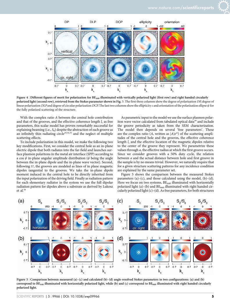
information may be cast, for instance to best bring out the geometryof a particular scattering problem or to best suit a researchers intu-ition. As example, we demonstrate the retrieval of different figures ofmerit for BE440 illuminated with vertically and right-handed circu-larly polarized light. Figure 4 shows the retrieved degree of polariza-tion DP, degree of linear polarization DLP and degree of circularpolarization DCP. As would be expected for a completely coherentscattering process, even though the scattered field presents a complexpolarization, the structure does not decrease the degree of polariza-tion of the incident field. The scattering conserves the incident totaldegree of polarizationDP5 1 for every k-vector independently of theincident polarization. As shown before, most of the scattered lighthas a degree of linear (circular) polarization that closely matches theincident light. Conversion from linear to circular polarization andvice versa, occurs in well defined regions where there is a quarterwave phase difference between the light emanating directly from thehole (polarized as the incident field over the entire back aperture) andthat radiated by the grooves (radially polarized over the back aper-ture owing to the p-polarized nature of plasmons).Figure 4 also shows the parameters of the ellipse described by the
electric field vector as a function of time, which are a frequently used
representation of the polarization state of fully polarized light25.The ellipticity e, defined as the ratio of semi-major and semi-minoraxis, takes values between 0 for linearly polarized light to6 1 for rightand left handed circularly polarized light, while y denotes theorientation of the ellipse. The angle y runs from2p/2 to p/2, where0 means that the major axis points along x. This representation notonly highlights the strong polarization conversion, already evident inthe degree of linear and circular polarization, but further allows adetailed tracking of the polarization ellipse orientation. In particular,it unveils the presence of so-called C-points which are polarizationsingularities where y is undefined, corresponding to nodes of purelycircularly polarized scattering50–55.
Comparison to a theoretical modelThe polarization information obtained with k-space polarimetry canserve as benchmark to test models currently used to describe the beha-vior of bullseye antennas. In particular, here we extend a commonsimplified, scalar model developed in Ref. 29,35,56 to describe theintensity distribution of scattering by BEs, to also predict all angularfeatures in its polarization content. In brief, the accepted model forscattering by structures in gold consisting of a nanoaperture sur-rounded by corrugations is that the radiation pattern is composed oftwo contributions. First, the nanoaperture itself is assumed to radiateinto the far field as a point source. Second, plasmons launched at thehole propagate into the film as a circular wave, approximated aseikSPPr=
ffiffir
p, where kSPP is the complex plasmon wave vector that
accounts for phase accumulation and loss. The surface plasmons sub-sequently excite the grooves that act as secondary sources radiating outinto the far field. In this model, the radiated scalar field observed at anobservationpoint a distanceR away fromthe scatterer, and at a viewingangle set by the parallel wave vector jkjjj is proportional to
eikR
R1zA
ðgrooves
eikSPPr coswffiffiffiffiffiffiffiffiffiffikSPPr
p eikjj:re{r=lc dr
" #: ð3Þ
Figure 3 | Angle-resolved Stokes parameters for BE440 in (a) and BE660 in (b), under linearly (first two rows) and circularly polarized light (second tworows).The Stokes parameters S1, S2, and S3 are normalized to the total scattered intensity S0. The color bar on S0 corresponds to counts in the CCD camera
in 0.1 s. Differences in the scales of S0 correspond to differences on the intensity at which each set of six measurements were performed.
www.nature.com/scientificreports
SCIENTIFIC REPORTS | 5 : 9966 | DOI: 10.1038/srep09966 4
With the complex ratio A between the central hole contributionand that of the grooves, and the effective coherence length lc as freeparameters, this scalar model has proven remarkably successful forexplaining beaming (i.e., S0) despite the abstraction of each groove asan infinitely thin radiating circle29,56,35 and the neglect of multiplescattering effects.To include polarization in this model, we make the following two
key modifications. First, we consider the central hole as an in-planeelectric dipole that both radiates into the far-field and launches sur-face plasmon polaritons in the metal air interface (SPP) according toa cos w in-plane angular amplitude distribution (w being the anglebetween the in-plane dipole and the in-plane wave vector). Second,following 57, the grooves are modeled as lines of in plane magneticdipoles tangential to the grooves. We take the in-plane dipolemoment induced in the central hole to be directly inherited fromthe input polarization of the driving field. Finally as radiation patternfor each elementary radiator in the system we use the full dipolarradiation pattern for dipoles above a substrate as derived by Lukoszet al.58
As parametric input to themodel we use the surface plasmon polar-iton wave vector calculated from tabulated optical data59 and includethe groove periodicity as taken from the SEM characterization.The model then depends on several ‘free parameters’. Theseare the complex ratio (A, written as jAjeiQ) of the scattering ampli-tudes of the central hole and the grooves, the effective coherencelength lc and the effective location of the magnetic dipoles relativeto the center of the groove they represent. We parametrize thesevalues through a, the effective radius at which the first groove occurs.Since we consider grooves with a 50% duty cycle, the relationbetween a and the actual distance between hole and first groove inthe sample is by no means trivial. However, we naturally require thatfor a given structure scattering patterns for any incidence conditionare explained by the same parameter set.Figure 5 shows the comparison between the measured Stokes
parameters (a)–(c), and those calculated using the model, (b)–(d).Here we focus on two systems, BE440 illuminated with horizontallypolarized light (a)–(b) and BE660 illuminated with right handed cir-cularly polarized light (c)–(d). As free parameters, for both structures
Figure 4 | Different figures of merit for polarization for BE440 illuminated with vertically polarized light (first row) and right handed circularlypolarized light (second row), retrieved from the Stokes parameter shown in Fig. 3. The first three columns show the degree of polarizationDP, degree of
linear polarizationDLP and degree of circular polarizationDCP. The last two columns show the ellipticity e and orientation of the polarization ellipsey for
the fully polarized scattering of the structure.
Figure 5 | Comparison between measured (a)–(c) and calculated (b)–(d) angle-resolved Stokes parameters in two configurations: (a) and (b)correspond to BE440 illuminated with horizontally polarized light, while (b) and (c) correspond to BE660 illuminated with right handed circularlypolarized light.
www.nature.com/scientificreports
SCIENTIFIC REPORTS | 5 : 9966 | DOI: 10.1038/srep09966 5

the ratio between the intensity scattered by the central hole and thegrooves is taken as jAj 5 0.1 mm21 and Q 5 p/2 and the effectivecoherence length as function of the pitch p is lc5 10p. The differencesin actual geometry result in a 5 149 nm for BE440 in (b) and a 5266 nm for BE660 in (d). Figure S1 in the supplementary informationshows the calculated patterns for all measurements in Fig. 3.Inspection of the calculation shows that the simplemodel reproducesall salient features in the data for all input polarizations, and for alloutput polarizations. These notably include the beaming in S0, theoccurrence of pockets of output polarization orthogonal to the input,as well as the angular regions in which linearly polarized light isconverted to circular polarization and vice versa.It is important to notice that, while the scalar model29,56,35 and the
vectorial formof it are very robust for predicting total intensity S0, theangle dependent polarization features encoded in S1, S2 and S3are much more sensitive than the total intensity to the choice ofthe free parameters. For instance, there is a large range of dipoleamplitude choices where the intensity pattern hardly changes,whereas the polarization features vary dramatically, as shown inthe supplementary information (Fig. S2). Also, we found that whilea good match to the data is obtained for a particular combination ofa, jAj and Q, this combination is not unique. This observation allowsus to draw two conclusions. On one hand, the fact that the simple,commonly used model is so successful for predicting intensity pat-terns should in retrospect not be read as a validation per se of its inputparameters, or of the involved approximations of abstracting the holeto a point and the grooves to infinitely thin circles of secondaryradiators. Indeed, we find that good matching of the model to justoverall intensity, i.e., S0 is possible for a very wide range of inputparameters. In contrast, matching the full set of Stokes parameters ismuch more demanding. Thereby we draw as second conclusion thatFourier polarimetry provides experimental signatures that are excel-lently suited to discriminate between different, improved models forthe response of plasmonic bullseyes, and by extension also for spirals,plasmonic crystals, and array antennas.
Conclusions and perspectivesWe have reported a new measurement technique to resolve thepolarization state of light scattered by a single nanostructure as func-tion of wave vector across an entire microscope back aperture. Thetechnique combines back focal plane imaging, also known as Fouriermicroscopy, with a polarimeter consisting of a linear polarizer andquarter wave plate. From just six camera images, all polarizationcontent can be retrieved as we demonstrate for a simple bullseyeantenna. Our results evidence some remarkable features of the scat-tering of BEs. The scattering pattern of BEs strongly depends on theincident polarization. Circular incident polarization result in rota-tional symmetric patterns while linear polarization results in patternselongated in the direction of the polarization, as consequence of thep-polarized nature of the involved plasmon excitation. While scat-tered light dominantly retains the polarization of the incident fieldthere are well defined regions at jkj ? 0 where the polarizations ofincident and scattered field are different, even orthogonal to theincident field, or completely converted in helicity from 21 to 0 or1 1.The reported measurement technique is equally applicable to
fluorescent nanostructures in which the total degree of polarizationis not unity, and is in fact an important parameter. For instance,while randomly oriented emitters should result inDP5 0, once theyare strongly coupled to the resonance of a plasmonic nanorod, theiremission is expected to inherit the orientation of the rod as dominantpolarization. Thus mapping the degree of polarization could be animportant quantifier to measure the efficiency with which a nanos-tructure controls emission polarization. We argue that Fourierpolarimetry is an easily implemented, yet extremely sensitive toolto test our understanding of a plethora of dielectric and metallic
nanophotonic structures. Beside plasmonics, this technique couldbe also a useful tool to study molecular orientation in biologicalsamples60 or in spin populations61, optically induced magneticorder62, or as a complement of other imaging techniques such asorientation imaging microscopy63.
1. Schuller, J. A. et al. Plasmonics for extreme light concentration andmanipulation.Nat. Mater. 9, 193–204 (2010).
2. Soukoulis, C. M. & Wegener, M. Past achievements and future challenges in thedevelopment of three-dimensional photonic metamaterials. Nat. Photonics 5,523–530 (2011).
3. Kildishev, A. V., Boltasseva, A. & Shalaev, V. M. Planar photonics withmetasurfaces. Science 339, 1232009 (2013).
4. Catchpole, K. R. et al. Plasmonics and nanophotonics for photovoltaics.MRS Bull.36, 461–467 (2011).
5. Lozano, G. et al. Plasmonics for solid-state lighting: enhanced excitation anddirectional emission of highly efficient light sources. Light Sci. Appl. 2, e66 (2013).
6. Wenger, J. & Rigneault, H. Photonic methods to enhance fluorescence correlationspectroscopy and single molecule fluorescence detection. Int. J. Mol. Sci. 11,206–221 (2010).
7. Onoda, M., Murakami, S. & Nagaosa, N. Hall effect of light. Phys. Rev. Lett. 93,083901 (2004).
8. Kavokin, A., Malpuech, G. & Glazov, M. Optical spin hall effect. Phys. Rev. Lett.95, 136601 (2005).
9. Haefner, D., Sukhov, S. & Dogariu, A. Spin hall effect of light in sphericalgeometry. Phys. Rev. Lett. 102, 123903 (2009).
10. Yin, X., Ye, Z., Rho, J., Wang, Y. & Zhang, X. Photonic spin hall effect atmetasurfaces. Science 339, 1405–1407 (2013).
11. O’Connor, D., Ginzburg, P., Rodríguez-Fortuño, F. J.,Wurtz, G. A. &Zayats, A. V.Spin–orbit coupling in surface plasmon scattering by nanostructures. Nat.Commun. 5, 5327 (2014).
12. Li, G. et al. Spin-enabled plasmonic metasurfaces formanipulating orbital angularmomentum of light. Nano Lett. 13, 4148–4151 (2013).
13. Lu, L., Joannopoulos, J. D. & Soljacic, M. Topological photonics.Nat. Photonics 8,821–829 (2014).
14. Newton, R. G. Scattering theory of waves and particles (Dover Publications Inc.,Mineola, NY, 2002).
15. García de Abajo, F. Colloquium: Light scattering by particle and hole arrays. Rev.Mod. Phys. 79, 1267–1290 (2007).
16. deVries, P., vanCoevorden, D. & Lagendijk, A. Point scatterers for classical waves.Rev. Mod. Phys. 70, 447–466 (1998).
17. Fallet, C. Angle resolved Mueller polarimetry, applications to periodic structures.Theses, Ecole Polytechnique X (2011).
18. Fallet, C. et al. Overlay measurements by mueller polarimetry in back focal plane.J. Micro/Nanolithogr., MEMS, MOEMS 10, 033017 (2011).
19. Arteaga, O., Maoz, B. M., Nichols, S., Markovich, G. & Kahr, B. Completepolarimetry on the asymmetric transmission through subwavelength hole arrays.Opt. Express 22, 13719–13732 (2014).
20. Kruk, S. S. et al. Spin-polarized photon emission by resonant multipolarnanoantennas. ACS Photonics 1, 1218–1223 (2014).
21. Lieb, M. A., Zavislan, J. M. & Novotny, L. Single-molecule orientationsdetermined by direct emission pattern imaging. J. Opt. Soc. Am. B 21, 1210–1215(2004).
22. Patra, D., Gregor, I., Enderlein, J. & Sauer, M. Defocused imaging of quantum-dotangular distribution of radiation. Appl. Phys. Lett. 87, 101103 (2005).
23. Berry, H. G., Gabrielse, G. & Livingston, A. E. Measurement of the stokesparameters of light. Appl. Opt. 16, 3200–3205 (1977).
24. Bass, M. et al. Handbook of Optics, Third Edition Volume I: Geometrical andPhysical Optics, Polarized Light, Components and Instruments(Set) (McGraw-Hill, Inc., New York, NY, USA, 2010), 3 edn.
25. Born, M. & Wolf, E. Principles of Optics (Cambridge University Press, 1999), 7edn.
26. Thio, T., Pellerin, K.M., Linke, R. A., Lezec, H. J. & Ebbesen, T.W. Enhanced lighttransmission through a single subwavelength aperture. Opt. Lett. 26, 1972–1974(2001).
27. Lezec, H. J. et al. Beaming light from a subwavelength aperture. Science 297,820–822 (2002).
28. Martín-Moreno, L., García-Vidal, F., Lezec, H., Degiron, A. & Ebbesen, T. Theoryof highly directional emission from a single subwavelength aperture surroundedby surface corrugations. Phys. Rev. Lett. 90, 167401 (2003).
29. Carretero-Palacios, S. et al. Mechanisms for extraordinary optical transmissionthrough bull’s eye structures. Opt. Express 19, 10429–10442 (2011).
30. Aouani, H. et al. unidirectional fluorescence emission of molecules in ananoaperture with plasmonic corrugations. Nano Lett. 11, 637–644 (2011).
31. Mahboub, O. et al. Optimization of bull’s eye structures for transmissionenhancement. Opt. Express 18, 11292–11299 (2010).
32. Drezet, A., Genet, C. & Ebbesen, T. Miniature plasmonic wave plates. Phys. Rev.Lett. 101, 043902 (2008).
33. Gorodetski, Y., Lombard, E., Drezet, A., Genet, C. & Ebbesen, T. W. A perfectplasmonic quarter-wave plate. Appl. Physi. Lett. 101, 201103 (2012).
www.nature.com/scientificreports
SCIENTIFIC REPORTS | 5 : 9966 | DOI: 10.1038/srep09966 6

34. Jiao, X. & Blair, S. Polarization multiplexed optical bullseye antennas. Plasmonics7, 39–46 (2012).
35. Yi, J.-M., Cuche, A., Devaux, E., Genet, C. & Ebbesen, T. W. Beaming visible lightwith a plasmonic aperture antenna. ACS Photonics 1, 365–370 (2014).
36. Curto, A. G. et al. Unidirectional emission of a quantum dot coupled to ananoantenna. Science 329, 930–933 (2010).
37. Bernal Arango, F., Kwadrin, A. & Koenderink, A. F. Plasmonic antennashybridized with dielectric waveguides. ACS Nano 6, 10156–10167 (2012).
38. Curto, A. G. et al. Multipolar radiation of quantum emitters with nanowire opticalantennas. Nat. Commun. 4, 1750 (2013).
39. Sersic, I., Tuambilangana, C. & Koenderink, A. F. Fourier microscopy of singleplasmonic scatterers. New J. Physi. 13, 083019 (2011).
40. Thomas, N. L., Houdre, R., Kotlyar, M. V., O’Brien, D. & Krauss, T. F. Exploringlight propagating in photonic crystals with fourier optics. J. Opt. Soc. Am. B 24,2964–2971 (2007).
41. Alaverdyan, Y. et al. Spectral and angular distribution of rayleigh scattering fromplasmon-coupled nanohole chains. Appl. Physi. Lett. 94, 021112 (2009).
42. Fontana, Y., Grzela, G., Bakkers, E. & Gomez-Rivas, J. Mapping the directionalemission of quasi-two-dimensional photonic crystals of semiconductornanowires using fourier microscopy. Phys. Rev. B 86, 245303 (2012).
43. Kwadrin, A. & Koenderink, A. F. Diffractive stacks of metamaterial lattices with acomplex unit cell: Self-consistent long-range bianisotropic interactions inexperiment and theory. Phys. Rev. B 89, 045120 (2014).
44. Taminiau, T. H., Karaveli, S., van Hulst, N. F. & Zia, R. Quantifying the magneticnature of light emission. Nat. Commun. 3, 979 (2012).
45. Dodson, C. M., Kurvits, J. A., Li, D. & Zia, R. Wide-angle energy-momentumspectroscopy. Opt. Lett. 39, 3927–3930 (2014).
46. Coenen, T. & Polman, A. Polarization-sensitive cathodoluminescence fouriermicroscopy. Opt. Express 20, 18679–18691 (2012).
47. Lozano, G., Barten, T., Grzela, G. & Gomez-Rivas, J. Directional absorption byphased arrays of plasmonic nanoantennae probed with time-reversed fouriermicroscopy. New J. Physi. 16, 013040 (2014).
48. Török, P., Munro, P. R. T. & Kriezis, E. E. High numerical aperture vectorialimaging in coherent optical microscopes. Opt. Express 16, 507–523 (2008).
49. Novotny, L. & Hecht, B. Principles of nano-optics (Cambridge Univ. Press,Cambridge, 2006).
50. Nye, J. F. Polarization effects in the diffraction of electromagnetic waves: The roleof dislocations. Proc. R. Soc. A 387, 105–132 (1983).
51. Hajnal, J. V. Observations of singularities in the electric and magnetic fields offreely propagating microwaves. Proc. R. Soc. A 430, 413–421 (1990).
52. Berry, M. V., Dennis, M. R. & Lee, Jr, R. L. Polarization singularities in the clearsky. New J. Physi. 6, 162 (2004).
53. Egorov, R., Soskin, M., Kessler, D. & Freund, I. Experimental measurements oftopological singularity screening in random paraxial scalar and vector opticalfields. Phys. Rev. Lett. 100, 103901 (2008).
54. Flossmann, F., O’Holleran, K., Dennis, M. & Padgett, M. Polarization singularitiesin 2d and 3d speckle fields. Phys. Rev. Lett. 100, 203902 (2008).
55. Burresi, M. et al. Observation of polarization singularities at the nanoscale. Phys.Rev. Lett. 102, 033902 (2009).
56. Gorodetski, Y., Drezet, A., Genet, C. & Ebbesen, T. Generating far-fieldorbital angular momenta from near-field optical chirality. Phys. Rev. Lett. 110,203906 (2013).
57. Brucoli, G. &Martín-Moreno, L. Comparative study of surface plasmon scatteringby shallow ridges and grooves. Phys. Rev. B 83, 045422 (2011).
58. Lukosz,W.&Kunz, R. E. Light emission bymagnetic and electric dipoles close to aplane dielectric interface. ii. radiation patterns of perpendicular oriented dipoles.J. Opt. Soc. Am. 67, 1615–1619 (1977).
59. Etchegoin, P. G., Le Ru, E. C. & Meyer, M. An analytic model for the opticalproperties of gold. J. Chem. Phys. 125, 164705 (2006).
60. Duboisset, J., Rigneault, H. & Brasselet, S. Filtering of matter symmetry propertiesby circularly polarized nonlinear optics. Phys. Rev. A 90, 063827 (2014).
61. Bottegoni, F., et al. Spin voltage generation through optical excitation ofcomplementary spin populations Nat. Mater. 13, , 790–795 (2014).
62. Kirilyuk, Andrei. Kimel, A., V. & Rasing, T. Ultrafast optical manipulation ofmagnetic order. Rev. Mod. Phys. 82, 2731–2784 (2010).
63. Brent L. A. Orientation imaging microscopy: Emerging and future applications.Phys. Rev. A 67, 11–17 (1997).
AcknowledgmentsThis work is part of the research program of the Foundation for Fundamental Research onMatter (FOM), which is financially supported by the The Netherlands Organization forScientific Research (NWO). This work is supported by NanoNextNL, a micro- andnanotechnology consortium of the Government of The Netherlands and 130 partners. A.F.K. gratefully acknowledges an NWO-Vidi grant for financial support.
Author contributionsC.I.O. conceived the experiment and performed the measurements. A.M. designed andfabricated the samples. C.I.O. and A.F.K. developed the theoretical model. A.F.K.supervised the project. All authors contributed to the manuscript.
Additional informationSupplementary information accompanies this paper at http://www.nature.com/scientificreports
Competing financial interests: The authors declare no competing financial interests.
How to cite this article: Osorio, C.I., Mohtashami, A. & Koenderink, A.F. K-spacepolarimetry of bullseye plasmon antennas. Sci. Rep. 5, 9966; DOI:10.1038/srep09966(2015).
This work is licensed under a Creative Commons Attribution 4.0 InternationalLicense. The images or other third party material in this article are included in thearticle’s Creative Commons license, unless indicated otherwise in the credit line; ifthe material is not included under the Creative Commons license, users will needto obtain permission from the license holder in order to reproduce thematerial. Toview a copy of this license, visit http://creativecommons.org/licenses/by/4.0/
www.nature.com/scientificreports
SCIENTIFIC REPORTS | 5 : 9966 | DOI: 10.1038/srep09966 7