K O CCHAPTERHAPTER AND S PARAMETERS Temperature Controller User Manual 3–3 Chapter 3: Keypad...
24
KEYPAD OPERATION AND SETUP PARAMETERS 3 3 3 CHAPTER CHAPTER CHAPTER In this Chapter... Display, LED and Keypad............................................................3–2 Keypad Operation ......................................................................3–3 Setup Parameter Listing .............................................................3–4 Regulation Mode Parameters.....................................................3–7 Operation Mode Parameters....................................................3–17 Initial Setting Parameters.........................................................3–19 Reset to Factory Default ...........................................................3–24
Transcript of K O CCHAPTERHAPTER AND S PARAMETERS Temperature Controller User Manual 3–3 Chapter 3: Keypad...

Keypad OperatiOn and Setup parameterS 333
ChapterChapterChapter
In this Chapter...Display, LED and Keypad ............................................................3–2
Keypad Operation ......................................................................3–3
Setup Parameter Listing .............................................................3–4
Regulation Mode Parameters .....................................................3–7
Operation Mode Parameters ....................................................3–17
Initial Setting Parameters .........................................................3–19
Reset to Factory Default ...........................................................3–24

Chapter 3: Keypad Operation and Setup Parameters
SOLO Temperature Controller User Manual3–2
Display, LED and KeypadThe SOLO temperature controller has a two color seven segment LED display, four types of LED status indicators and four function buttons.
9696
PV
SOLO
SV
SET
OUT1 OUT2 ALM1AT ALM2 ALM3 F C
OUT1, OUT2 LEDs
SV Display
PV Display
ALM1, ALM2, ALM3, LEDs
°F, °C LEDs
Up ButtonSET Button
Down ButtonRotate Button
Auto Tuning LED
PV DisplayThe Process Value Display. Displays the value from the input source or the parameter source.
SV DisplayThe Set Value Display. Displays the set point of the process, the parameter operation read value, manipulated variable, or the set value of the parameter.
AT LED IndicatorAuto Tuning LED flashes when the Auto Tuning operation is ON.
OUT1, OUT2 LED IndicatorsOutput 1 and Output 2 LED indicators light when the output is ON.
°F, °C LED IndicatorsTemperature unit LED. °C: Celsius, °F: Fahrenheit
ALM1, ALM2, ALM3 LED IndicatorsAlarm output LED indicators light when appropriate alarm is activated. ALM2 and ALM3 indicators are available on series SL4896 and SL9696 only.

SOLO Temperature Controller User Manual 3–3
Chapter 3: Keypad Operation and Setup Parameters
2nd Ed. Rev D 04/18
Keypad OperationFunction Buttons
SET Button
Press the SET button to select the desired function mode and confirm the setting value.
Rotate Button
Press the Rotate button to select parameters within the function mode.
Down Button
Press the Down button to decrease values displayed on the SV display. Hold down this button to speed up the decrement.
Up Button
Press the Up button to increase values displayed on the SV display. Hold down this button to speed up the increment.
Initial Power upWhen power is first applied to the temperature controller, the module information splash screen appears. This screen shows the firmware version on the PV display and the two output types for that particular model on the SV display. After three seconds, the controller will automatically proceed to the Operation mode main screen.
Keypad OperationThe temperature controller has three function modes: Initial Setting mode, Operation mode and Regulation mode. Press and hold the SET button for three seconds to go into the Initial Setting mode. Press the SET button for less than three seconds to access the Regulation mode. Press the Rotate button while inside any of the three function modes to scroll through the individual parameters for each function mode. Use the Up and Down buttons to change the individual parameter values. Pressing the SET button saves the parameter values. Press the SET button again to return the controller to the Operation mode main screen.
Page: 3–7 Page: 3–17 Page: 3–19
Operation Mode
SETHold for 3 sec.
SET
Initial SettingMode
RegulationMode
SETPress for lessthan 3 sec.
Initial SettingParameters
OperationParameters
RegulationParameters
SET

Chapter 3: Keypad Operation and Setup Parameters
SOLO Temperature Controller User Manual3–4
Setup Parameter ListingRegulation Mode Parameters
Press the ; button to access these parameters.
Regulation Mode Parameter Availablity
ID # Display Parameter Name
Controller Type Control Mode Heating / Cooling
RR(E
)
VR(E
)
VV(E
)
CR(E
)
CV(E
)
LR(E
)
LV(E
)
PID
ON /O
FF
Man
ual
Ram
p / S
oak
Heat
ing
Cool
ing
Heat
ing
/ Coo
ling
Cool
ing
/ Hea
ting
P1-1 At Auto Tuning 4 4 4 4 4 4 4 4 - - - 4 4 4 4
P1-2 pidn PID Parameter Group 4 4 4 4 4 4 4 4 - - 4 4 4 4 4
P1-3 svn Target SV 4 4 4 4 4 4 4 4 - - 4 4 4 4 4
P1-4 pn Proportion Band 4 4 4 4 4 4 4 4 - - 4 4 4 4 4
P1-5 in Integral Time 4 4 4 4 4 4 4 4 - - 4 4 4 4 4
P1-6 dn Derivative Time 4 4 4 4 4 4 4 4 - - 4 4 4 4 4
P1-7 PDof PD Control Offset 4 4 4 4 4 4 4 4 - - 4 4 4 4 4
P1-8 iofn Integral Offset 4 4 4 4 4 4 4 4 - - 4 4 4 4 4
P1-9 hts Heating Hysteresis 4 4 4 4 4 4 4 - 4 - - 4 - 4 4
P1-10 Cts Cooling Hysteresis 4 4 4 4 4 4 4 - 4 - - - 4 4 4
P1-11 htpd Output 1 Heating Period 4 4 4 4 4 4 4 4 - 4 4 4 - 4 -P1-12 Clpd Output 1 Cooling Period 4 4 4 4 4 4 4 4 - 4 4 - 4 - 4
P1-13 hCpd Output 2 Period 4 4 4 4 4 4 4 4 - 4 4 - - 4 4
P1-14 Coef Proportion Band Coefficient 4 4 4 4 4 4 4 4 - - 4 - - 4 4
P1-15 dead Dead Band 4 4 4 4 4 4 4 4 4 - 4 - - 4 4
P1-16 tpof PV Offset 4 4 4 4 4 4 4 4 4 4 4 4 4 4 4
P1-17 Crhi Analog High Adjustment - - - 4 4 4 4 4 4 4 4 4 4 4 4
P1-18 Crlo Analog Low Adjustment - - - 4 4 4 4 4 4 4 4 4 4 4 4

SOLO Temperature Controller User Manual 3–5
Chapter 3: Keypad Operation and Setup Parameters
2nd Ed. Rev D 04/18
Operation Mode ParametersPress the • button to access these parameters.
Operation Mode Parameter Availablity
ID # Display Parameter Name
Controller Type Control Mode Heating / Cooling
RR(E
)
VR(E
)
VV(E
)
CR(E
)
CV(E
)
LR(E
)
LV(E
)
PID
ON /O
FF
Man
ual
Ram
p / S
oak
Heat
ing
Cool
ing
Heat
ing
/ Coo
ling
Cool
ing
/ Hea
ting
P2-1 r-s Run / Stop 4 4 4 4 4 4 4 4 4 4 4 4 4 4 4
P2-2 ptrn Starting Ramp / Soak Pattern 4 4 4 4 4 4 4 - - - 4 4 4 4 4
P2-3 sp Decimal Point Position 4 4 4 4 4 4 4 4 4 4 4 4 4 4 4
P2-4 al1h Alarm 1 High Limit 4 4 4 4 4 4 4 4 4 4 4 4 4 4 4
P2-5 al1l Alarm 1 Low Limit 4 4 4 4 4 4 4 4 4 4 4 4 4 4 4
P2-6 al2h Alarm 2 High Limit 4 4 4 4 4 4 4 4 4 4 4 4 4 4 4
P2-7 al2l Alarm 2 Low Limit 4 4 4 4 4 4 4 4 4 4 4 4 4 4 4
P2-8 al3h Alarm 3 High Limit 4 4 4 4 4 4 4 4 4 4 4 4 4 - -P2-9 al3l Alarm 3 Low Limit 4 4 4 4 4 4 4 4 4 4 4 4 4 - -P2-10 loC Lock Mode 4 4 4 4 4 4 4 4 4 4 4 4 4 4 4
P2-11 out1 Output 1 Level 4 4 4 4 4 4 4 4 4 4 4 4 4 4 4
P2-12 out2 Output 2 Level 4 4 4 4 4 4 4 4 4 4 4 - - 4 4
Chapter 3: Keypad Operation and Setup Parameters
SOLO Temperature Controller User Manual3–6
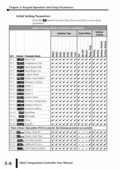
Initial Setting ParametersPress the ; button for more than three seconds to access these parameters.
Initial Setting Mode Parameter Availablity
ID # Display Parameter Name
Controller Type Control Mode Heating / Cooling
RR(E
)
VR(E
)
VV(E
)
CR(E
)
CV(E
)
LR(E
)
LV(E
)
PID
ON /O
FF
Man
ual
Ram
p / S
oak
Heat
ing
Cool
ing
Heat
ing
/ Coo
ling
Cool
ing
/ Hea
ting
P3-1 inpt Input Type 4 4 4 4 4 4 4 4 4 4 4 4 4 4 4
P3-2 tpun Temperature Unit 4 4 4 4 4 4 4 4 4 4 4 4 4 4 4
P3-3 tp-h Input Range High 4 4 4 4 4 4 4 4 4 4 4 4 4 4 4
P3-4 tp-l Input Range Low 4 4 4 4 4 4 4 4 4 4 4 4 4 4 4
P3-5 Ctrl Control Mode 4 4 4 4 4 4 4 4 4 4 4 4 4 4 4
P3-6 Patn Ramp / Soak Pattern* 4 4 4 4 4 4 4 4 4 4 4 4 4 4 4
P3-7 s-hC Heating / Cooling 4 4 4 4 4 4 4 4 4 4 4 4 4 4 4
P3-8 ala1 Alarm 1 4 4 4 4 4 4 4 4 4 4 4 4 4 4 4
P3-9 ala2 Alarm 2 4 4 4 4 4 4 4 4 4 4 4 4 4 4 4
P3-10 ala3 Alarm 3 4 4 4 4 4 4 4 4 4 4 4 4 4 4 4
P3-11 sala System Alarm 4 4 4 4 4 4 4 4 4 4 4 4 4 4 4
P3-12 Cosh On-Line Configuration 4 4 4 4 4 4 4 4 4 4 4 4 4 4 4
P3-13 C-SL Modbus Protocol 4 4 4 4 4 4 4 4 4 4 4 4 4 4 4
P3-14 C-no Network Address 4 4 4 4 4 4 4 4 4 4 4 4 4 4 4
P3-15 bps Baud Rate 4 4 4 4 4 4 4 4 4 4 4 4 4 4 4
P3-16 LEn Bit Length 4 4 4 4 4 4 4 4 4 4 4 4 4 4 4
P3-17 Prty Parity 4 4 4 4 4 4 4 4 4 4 4 4 4 4 4
P3-18 Stop Stop Bit 4 4 4 4 4 4 4 4 4 4 4 4 4 4 4
*Once a Ramp / Soak pattern (P3-6) is selected, the following parameters are available.
P3-19 spmn Ramp / Soak SV 4 4 4 4 4 4 4 - - - 4 4 4 4 4
P3-20 timn Ramp / Soak Time 4 4 4 4 4 4 4 - - - 4 4 4 4 4
P3-21 psxn Last Step Number 4 4 4 4 4 4 4 - - - 4 4 4 4 4
P3-22 CYCn Additional Cycles 4 4 4 4 4 4 4 - - - 4 4 4 4 4
P3-23 linn Next Pattern Number 4 4 4 4 4 4 4 - - - 4 4 4 4 4

SOLO Temperature Controller User Manual 3–7
Chapter 3: Keypad Operation and Setup Parameters
2nd Ed. Rev D 04/18
Regulation Mode ParametersPress the ; button to access these parameters.
At Auto Tuning ID Number P1-1
Range: On - Auto Tuning activated Off - Auto Tuning deactivated
When this parameter is set to On, the controller begins auto tuning. After auto tuning is complete, the parameter is set to Off automatically. If this parameter is set to Off during the auto tuning process, the controller stops the auto tuning process immediately and does not change any PID parameter.
PIDn PID Parameter Group ID Number P1-2
This parameter name will be displayed as one of the following.
PID0 PID Parameter Group 0PID1 PID Parameter Group 1PID2 PID Parameter Group 2PID3 PID Parameter Group 3PID4 PID Parameter Group Auto SelectPID PID Parameter Group for Event 2 Input
Range: PID0 to PID4
The SOLO controller can store up to 4 PID parameter groups (PID0 -
PID3) for regular operation. The PID Parameter Group parameter sets which PID group (PID0 - PID3) to use for control. The SV display shows the Target SV assigned to the PID group. (For more information about the Target SV, refer to P1-3 Target SV)
When PID4 is selected as the PID parameter group, the controller automatically chooses the one PID parameter group (PID0 - PID3) that has a Target SV that is the nearest to the SV set by the operator and uses that group for control.
PID is a special PID parameter group for the SL4896 and SL9696 series controllers Event inputs. This is the PID group that the controller uses when the Event 2 input is on. To configure the PID parameter for this parameter group, the Event 2 input must be active.
SVn Target SV ID Number P1-3
This parameter name will be displayed as one of the following. Only the Target SV for the selected PID Parameter Group (PID0, P1-2) will be displayed when accessing this parameter.

Chapter 3: Keypad Operation and Setup Parameters
SOLO Temperature Controller User Manual3–8
SV0 Target SV of PID Parameter Group 0SV1 Target SV of PID Parameter Group 1SV2 Target SV of PID Parameter Group 2Sv3 Target SV of PID Parameter Group 3sv Target SV of PID Parameter Group for Event 2 Input
Range: -99.9 to 999.9
(For more information about the parameter groups, refer to P1-2 PID Parameter Group.)
The Target SV is the setting value that each parameter group works toward. When the Target SV is the closest to the SV of the PID groups, this value is used to select which tuning parameters are used by the controller. The controller can store up to four PID parameter groups (PID0, - PID3) for regular operation. One of the PID parameter groups can be selected manually, or the controller selects the PID parameter group that has a Target SV that is the nearest to the SV set by the operator. If there are two or more PID parameter groups that have SV values equally close to the current PV, the controller uses the lowest number parameter group (eg. If parameter groups 0 - 3 have the same Target SV, the controller uses the parameter group 0).
The parameter SV is the Target SV of the PID parameter group for Event 2 input. This parameter is only displayed when the Event 2 input is on. The Event 2 input is only available on the SL4896 and SL9696 series controllers.
Pn Proportion Band ID Number P1-4
This parameter name will be displayed as one of the following. Only the Proportion Band for the selected PID Parameter Group (PID0, P1-2) will be displayed when accessing this parameter.
p0 Proportion Band of PID Parameter Group 0p1 Proportion Band of PID Parameter Group 1p2 Proportion Band of PID Parameter Group 2p3 Proportion Band of PID Parameter Group 3p Proportion Band of PID Parameter Group for Event 2 Input
Range: 0.1 to 999.9
(For more information about the parameter groups, refer to P1-2 PID Parameter Group.)
The Proportion Band is a parameter group used for PID control. The controller can store up to four PID parameter groups (PID0, - PID3) for regular operation. One of the PID parameter groups can be selected manually, or the controller selects the PID parameter group that has a Target SV that is the nearest to the SV set by the operator.
The parameter P is the Proportion Band of the PID parameter group for

SOLO Temperature Controller User Manual 3–9
Chapter 3: Keypad Operation and Setup Parameters
2nd Ed. Rev D 04/18
Event 2 input. This parameter is only displayed when the Event 2 input is on. The Event 2 input is only available on the SL4896 and SL9696 series controllers.
In Integral Time ID Number P1-5
This parameter name will be displayed as one of the following. Only the Integral Time for the selected PID Parameter Group (PID0, P1-2) will be displayed when accessing this parameter.
i0 Integral Time of PID Parameter Group 0i1 Integral Time of PID Parameter Group 1i2 Integral Time of PID Parameter Group 2i3 Integral Time of PID Parameter Group 3i Integral Time of PID Parameter Group for Event 2 Input
Range: 0 to 9999 (Sec)
(For more information about the parameter groups, refer to P1-2 PID Parameter Group.)
The Integral Time is a parameter group used for PID control. The controller can store up to four PID parameter groups (PID0, - PID3) for regular operation. One of the PID parameter groups can be selected manually, or the controller selects the PID parameter group that has a Target SV that is the nearest to the SV set by the operator.
The parameter i is the Integral Time of the PID parameter group for Event 2 input. This parameter is only displayed when the Event 2 input is on. The Event 2 input is only available on the SL4896 and SL9696 series controllers.
dn Derivative Time ID Number P1-6
This parameter name will be displayed as one of the following. Only the Derivative Time for the selected PID Parameter Group (PID0, P1-2) will be displayed when accessing this parameter.
d0 Derivative Time of PID Parameter Group 0d1 Derivative Time of PID Parameter Group 1d2 Derivative Time of PID Parameter Group 2d3 Derivative Time of PID Parameter Group 3d Derivative Time of PID Parameter Group for Event 2 Input
Range: 0 to 9999 (Sec)
(For more information about the parameter groups, refer to P1-2 PID Parameter Group.)
The Derivative Time is a parameter group used for PID control. The controller can store up to four PID parameter groups (PID0, - PID3) for regular operation. One of the PID parameter groups can be selected manually, or the controller selects the PID parameter group that has a

Chapter 3: Keypad Operation and Setup Parameters
SOLO Temperature Controller User Manual3–10
Target SV that is the nearest to the SV set by the operator.
The parameter d is the Derivative Time of the PID parameter group for Event 2 input. This parameter is only displayed when the Event 2 input is on. The Event 2 input is only available on the SL4896 and SL9696 series controllers.
pdof PD Control Offset ID Number P1-7
Range: 0.0 to 100.0 (%)
The PD Control Offset parameter is available when the P or PD control is selected [Integral Time parameter (In, P1-5) is zero].
This parameter defines the offset of the output. When the P or PD control is used, the control cannot stabilize the PV at the SV because the output is zero when the PV is equal to the SV. This parameter modifies the output level when the PV is equal to the SV.
iofn Integral Offset ID Number P1-8
This parameter name will be displayed as one of the following.
iof0 Integral Offset of PID Parameter Group 0iof1 Integral Offset of PID Parameter Group 1iof2 Integral Offset of PID Parameter Group 2iof3 Integral Offset of PID Parameter Group 3iof Integral Offset of PID Parameter Group for Event 2 Input
Range: 0.0 to 100.0 (%)
(For more information about the parameter groups, refer to PID Parameter Group, P1-2.)
The Integral Offset parameter is available when the PI or PID control is selected. [Integral Time parameter (In, P1-5) is not zero.]
The Auto Tuning process will decide the offset value automatically.
If this parameter is not used (iof = 0), the output is zero when the PV is equal to the SV. If the Integral Time parameter (In, P1-5) is used only to eliminate the steady error, it may take a long time to reach the SV because it needs time to accumulate the error. In this case, this parameter is useful. This parameter defines the default output level on start up. It will inprove the speed that the PV reaches the SV.
The parameter iof is the Integral Offset of the PID parameter group for Event 2 input. This parameter is only displayed when the Event 2 input is on. The Event 2 input is only available on the SL4896 and SL9696 series controllers.

SOLO Temperature Controller User Manual 3–11
Chapter 3: Keypad Operation and Setup Parameters
2nd Ed. Rev D 04/18
hts Heating Hysteresis ID Number P1-9
Range: 0.0 to 999.9
The Heating Hysteresis parameter defines the amount that the PV must go below the SV before the output turns on. This parameter is available only for On / Off control with an output programmed for heating.
hts Heating Hysteresis
PV
SV
ON
OFF
Output
Cts Cooling Hysteresis ID Number P1-10
Range: 0.0 to 999.9
The Cooling Hysteresis parameter defines the amount that the PV must go above the SV before the output turns on. This parameter is available only for On / Off control with an output programmed for cooling.
Cts Cooling Hysteresis
PV
SV
ON
OFF
Output
htpd Output 1 Heating Period ID Number P1-11
Range: 0.5 to 99 seconds
The Output 1 Heating parameter defines one output period or the duration of one on / off cycle for Output 1.
HTPD Output 1 Heating Period
This parameter is available when Output 1 is programmed as a heating output in the PID or Ramp / Soak mode.
Clpd Output 1 Cooling Period ID Number P1-12
Range: 0.5 to 99 seconds
The Output 1 Cooling parameter defines one output period or the duration of one on / off cycle for Output 1.
ClPD Output 1 Cooling Period
This parameter is available when Output 1 is programmed as a cooling output in the PID or Ramp / Soak mode.

Chapter 3: Keypad Operation and Setup Parameters
SOLO Temperature Controller User Manual3–12
HCpd Output 2 Period ID Number P1-13
Range: 0.5 to 99 seconds
The Output 1 Cooling parameter defines one output period or the duration of one on / off cycle for Output 2.
hCPD Output 2 Period
This parameter is available when Output 2 is programmed as a heating or cooling output in the PID or Ramp / Soak mode.
Coef Proportion Band Coefficient ID Number P1-14
Range: 0.01 to 99.99
This Proportion Band Coefficient parameter is available when a dual output mode (heating and cooling) is selected. This parameter allows the second output control to have a different proportional setting than the first output control. The first output control proportional band setting is multiplied by this parameter to create a proportional band setting for the second output control.
(First Output) Proportion Band * Proportion Band Coefficient = Second Proportional Band
(Pn, P1-4) (Coef , P1-14)
dead Dead Band ID Number P1-15
Range: The range varies according to the Decimal Point Position (SP, P2-3).
sp 0 1 2 3
dead -99 to 999 -99.9 to 999.9 -9.99 to 99.99 -.999 to 9.999
The dead band zone is the area around the SV where the output is not effected by the proportional control value (PV). For PID control, as long as the PV remains within the dead band zone, the output is not affected by the proportional control. The integral and derivative controls ignore the dead band setting and may cause the output to be on within the dead band zone.
PV 0
Output Dead band: dead band width=positive
Set point
Heating Cooling
dead
Dual Control PID controlpositive dead band
PV 0
Output Dead band: dead band width=negative
Set point
Heating Cooling
dead
Dual Control PID controlnegative dead band
For On / Off type control the Dead Band parameter defines the area around the SV where the output remains off. The PV must go beyond the dead band range in order for either output 1 or output 2 to turn on.
SOLO Temperature Controller User Manual 3–13
Chapter 3: Keypad Operation and Setup Parameters
2nd Ed. Rev D 04/18
OFF PV
Set point
ON
Heating
Dead band
Heating hysteresis Cooling hysteresis
Cooling
hts Cts
dead
Dual Loop On / Off controloutput operation
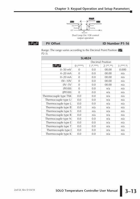
tpof PV Offset ID Number P1-16
Range: The range varies according to the Decimal Point Position (SP , P2-3).
SL4824Decimal Position
tpof 0 (****) 1 (*.***) 2 (**.**) 3 (***.*)0~50 mV 0 0.0 00.00 0.0004~20 mA 0 0.0 00.00 n/a0~20 mA 0 0.0 00.00 n/a0V~10V 0 0.0 00.00 n/a0V~5V 0 0.0 00.00 n/a(Pt100) 0 0.0 n/a n/a(JPt100) 0 0.0 n/a n/a
Thermocouple type TXK 0.0 0.0 n/a n/aThermocouple type U 0.0 0.0 n/a n/aThermocouple type L 0.0 0.0 n/a n/aThermocouple type B 0.0 n/a n/a n/aThermocouple type S 0.0 n/a n/a n/aThermocouple type R 0.0 n/a n/a n/aThermocouple type N 0.0 0.0 n/a n/aThermocouple type E 0.0 0.0 n/a n/aThermocouple type T 0.0 0.0 n/a n/aThermocouple type J 0.0 0.0 n/a n/a
Thermocouple type K 0.0 0.0 n/a n/a

Chapter 3: Keypad Operation and Setup Parameters
SOLO Temperature Controller User Manual3–14
SL4848 / SL4896 / SL9696Decimal Position
tpof 0 (****) 1 (*.***) 2 (**.**) 3 (***.*)0~50 mV 0 0.0 00.00 0.0004~20 mA 0 0.0 00.00 00.000~20 mA 0 0.0 00.00 00.000V~10V 0 0.0 00.00 00.000V~5V 0 0.0 00.00 00.00(Pt100) 0 0.0 n/a n/a(JPt100) 0 0.0 n/a n/a
Thermocouple type TXK 0.0 0.0 n/a n/aThermocouple type U 0.0 0.0 n/a n/aThermocouple type L 0.0 0.0 n/a n/aThermocouple type B 0.0 n/a n/a n/aThermocouple type S 0.0 n/a n/a n/aThermocouple type R 0.0 n/a n/a n/aThermocouple type N 0.0 0.0 n/a n/aThermocouple type E 0.0 0.0 n/a n/aThermocouple type T 0.0 0.0 n/a n/aThermocouple type J 0.0 0.0 n/a n/a
Thermocouple type K 0.0 0.0 n/a n/a
This parameter is used to add an offset value to the PV.
CrHi Analog High Adjustment ID Number P1-17
The Analog High Adjustment parameter is used to adjust the actual analog output value when the output is 100%. To set up this parameter, place the SOLO controller in the Manual control mode and set the Output 1 Level (out1, P2-11) to 100% then increase / decrease the parameter value to get the desired analog output value.
The tables below show the approximate Analog High Adjustment values needed to obtain the desired output value. The actual controller output will vary. Check and adjust the values until the desired output level is achieved.

SOLO Temperature Controller User Manual 3–15
Chapter 3: Keypad Operation and Setup Parameters
2nd Ed. Rev D 04/18
Voltage Output0V 1V 2V 3V 4V 5V 6V 7V
Crhi -7589 -6830 -6071 -5312 -4553 -3795 -3036 -22778V 9V 10V
Crhi -1518 -758 0
Current Output0mA 1mA 2mA 3mA 4mA 5mA 6mA 7mA
Crhi -7198 -6838 -6478 -6118 -5758 -5398 -5038 -46788mA 9mA 10mA 11mA 12mA 13mA 14mA 15mA
Crhi -4319 -3959 -3599 -3239 -2879 -2519 -2159 -179916mA 17mA 18mA 19mA 20mA
Crhi -1440 -1080 -720 -360 0
Note: When decreasing the parameter value for Analog High Adjustment below -1999, the SOLO display will “roll over” to -0, indicating a value of -2000. Two “roll overs” equal a value of -4000 and so forth. For example, to enter a value of -5312 for Analog High Adjustment, hold the , button until the SOLO display “rolls over” two times and the display reads -1312.
Note: The output may be saturated before it reaches the minimum or maximum value.
This parameter is available when Output 1 is Current or Linear Voltage.
Crlo Analog Low Adjustment ID Number P1-18
The Analog Low Adjustment parameter is used to adjust the actual analog output value when the output is 0%. To set up this parameter, place the SOLO controller in the Manual control mode and set the Output 1 Level (out1, P2-11) to 0% then increase / decrease the parameter value to get the desired analog output value.
The tables below show the approximate Analog Low Adjustment values needed to obtain the desired output value. The actual controller output will vary. Check and adjust the values until the desired output level is achieved.
Current Output0mA 1mA 2mA 3mA 4mA 5mA 6mA 7mA
Crlo -1440 -1080 -720 -360 0 360 720 10808mA 9mA 10mA 11mA 12mA 13mA 14mA 15mA
Crlo 1440 1799 2159 2519 2879 3239 3599 395916mA 17mA 18mA 19mA 20mA
Crlo 4319 4678 5038 5398 5758

Chapter 3: Keypad Operation and Setup Parameters
SOLO Temperature Controller User Manual3–16
Voltage Output0V 1V 2V 3V 4V 5V 6V 7V
Crlo 0 759 1518 2277 3036 3795 4553 53128V 9V 10V
Crlo 6071 6830 7589
Note: When increasing the parameter value of Analog Low Adjustment above 9999, the SOLO display will “roll up” to 0000, indicating a value of 10000. For example,
to enter a value of 10625 for Analog Low Adjustment, hold the ’. button until the SOLO display reads 0625.
Note: The output may be saturated before it reaches the minimum or maximum value.
This parameter is available when Output 1 is Current or Linear Voltage.

SOLO Temperature Controller User Manual 3–17
Chapter 3: Keypad Operation and Setup Parameters
2nd Ed. Rev D 04/18
Operation Mode ParametersPress the ‘ button to access these parameters.
r-s Run / Stop ID Number P2-1
The Run / Stop parameter is used to control the operational status of the SOLO Controller. The available range varies according to the control mode and the status of the EVENT 1 input. The Event 1 input is available only for the SL4896 and SL9696 series controllers.
PID, On / Off and Manual Control ModesRun Stop
Event 1 input is off. (Event 1 input is open.) run kstp
Event 1 input is on. (Event 1 input is closed.) N/A stop,estp
Ramp / Soak Control ModeRun Hold Stop
Event 1 input is off. (Event 1 input is open.) run phod kstp,pstpEvent 1 input is on. (Event 1 input is closed.) N/A N/A stop,estp
run Run modekstp Stop modestop Stop mode (The controller was in Stop mode when the
Event 1 input was closed.)
estp Stop mode (The controller was in Run mode when the Event 1 input was closed.)
Phod Ramp / Soak control is on hold. The controller keeps the current Ramp / Soak step number and time. Ramp / Soak control continues when the mode is changed to Run.
pstp Ramp / Soak control is stopped. The controller restarts the Ramp / Soak control at the first step when the mode is changed to Run.
ptrn Starting Ramp / Soak Pattern ID Number P2-2
Range: 0 to 7Select the Ramp / Soak pattern number to start the Ramp / Soak control.
sp Decimal Point Position ID Number P2-3
Range: 0 (****) 1 (***.*) 2 (**.**) 3 (*.***)
This parameter defines the decimal point position on the PV and SV display.
al1h Alarm 1 High Limit ID Number P2-4
This parameter is used to set the high limit for Alarm 1. The range varies according to other parameter values.

Chapter 3: Keypad Operation and Setup Parameters
SOLO Temperature Controller User Manual3–18
al1l Alarm 1 Low Limit ID Number P2-5This parameter is used to set the low limit for Alarm 1. The range varies according to other parameter values.
al2h Alarm 2 High Limit ID Number P2-6This parameter is used to set the high limit for Alarm 2. The range varies according to other parameter values.
al2l Alarm 2 Low Limit ID Number P2-7This parameter is used to set the low limit for Alarm 2. The range varies according to other parameter values.
al3h Alarm 3 High Limit ID Number P2-8This parameter is used to set the high limit for Alarm 3. The range varies according to other parameter values.
al3l Alarm 3 Low Limit ID Number P2-9This parameter is used to set the low limit for Alarm 3. The range varies according to other parameter values.
loC Lock Mode ID Number P2-10
Range: off The Lock feature is disabled.loC1 Lock Mode 1LoC2 Lock Mode 2
Lock Mode 1: All key pad operation is ignored. Press the ; key and the ‘ key at the same time to cancel this lock mode.
Lock Mode 2: All key pad operation is ignored except changing the SV. Press the ; key and the ‘ key at the same time to cancel this lock mode.
out1 Output 1 Level ID Number P2-11
Range: 0.0 to 100 (%)
The value for this parameter can be changed in the Manual control mode. In other control modes, this parameter is read-only.
out2 Output 2 Level ID Number P2-12
Range: 0.0 to 100 (%)
This parameter is available when Output 2 is used. Refer to the Heating / Cooling parameter (S-HC, P3-7) to disable / enable Output 2. The value for this parameter can be changed in the Manual control mode. In other control modes, this parameter is read-only.

SOLO Temperature Controller User Manual 3–19
Chapter 3: Keypad Operation and Setup Parameters
2nd Ed. Rev D 04/18
Initial Setting ParametersPress the ; button for more than three seconds to access these parameters.
Inpt Input Type ID Number P3-1
This parameter defines the input signal type.
Thermocouple* Type and Temperature Range
Input Temperature Sensor Type LED Display Temperature Range
Thermocouple TXK type txk -328 ~ 1472°F (-200 ~ 800°C)
Thermocouple U type u -328 ~ 932°F (-200 ~ 500°C)
Thermocouple L type l -328 ~ 1562°F (-200 ~ 850°C)
Thermocouple B type b 212 ~ 3272°F (100 ~ 1800°C)
Thermocouple S type s 32 ~ 3092°F (0 ~ 1700°C)
Thermocouple R type r 32 ~ 3092°F (0 ~ 1700°C)
Thermocouple N type n -328 ~ 2372°F (-200 ~ 1300°C)
Thermocouple E type e 32 ~ 1112°F (0 ~ 600°C)
Thermocouple T type t -328 ~ 752°F (-200 ~ 400°C)
Thermocouple J type j -148 ~ 2192°F (-100 ~ 1200°C)
Thermocouple K type k -328 ~ 2372°F (-200 ~ 1300°C)
RTD Type and Temperature RangeInput Temperature Sensor Type LED Display Temperature RangePlatinum Resistance (Pt100) pt -328 ~ 1112°F (-200 ~ 600°C)
Platinum Resistance (JPt100) jpt -4 ~ 752°F (-20 ~ 400°C)
Voltage Input Type and Input Range
Voltage Input Type LED Display Temperature Range
0~50mV Analog Input mv -999 ~ 9999
0V~10V Analog Input v10 -999 ~ 9999
0V~5V Analog Input v5 -999 ~ 9999
Current Input Type and Input Range
Current Input Type LED Display Temperature Range
4~20mA Analog Input ma4 -999 ~ 9999
0~20mA Analog Input ma0 -999 ~ 9999
*Note - Use only ungrounded thermocouples
tpun Temperature Unit ID Number P3-2Range: F, CThis parameter is available when the parameter Input Type is a thermocouple or RTD.

Chapter 3: Keypad Operation and Setup Parameters
SOLO Temperature Controller User Manual3–20
tp-h Input Range High ID Number P3-3
Range: From the value of Input Range Low to 9999.
This parameter defines the high limit of the PV. This is the maximum value of the operational temperature range. In operation, if the PV value is higher than the tp-h value, th PV flashes to indicate an error and the controller outputs shut off. The SV value cannot exceed the
tp-h value. This parameter cannot be lower than the Input Range Low parameter (tp-l, P3-4).
tp-l Input Range Low ID Number P3-4
Range: From -999 to the value of Input Range High.
This parameter defines the low limit of the PV. This is the minimum value of the operational temperature range. In operation, if the PV value is lower than the tp-l value, th PV flashes to indicate an error and the controller outputs shut off. The SV value cannot be set lower than the tp-L value. This parameter cannot be higher than the Input Range High parameter (tp-h, P3-3).
Ctrl Control Mode ID Number P3-5
Range: pid PID control modeonof On / Off control modemanu Manual control modepro6 Ramp / Soak control mode
This parameter is used to select one of the control modes. See Chapter 5 for a complete discription of each control mode.
PAtn Ramp / Soak Pattern ID Number P3-6
Range: oFF Ramp / Soak pattern is not selected. 0 to 7 Ramp / Soak pattern number.
This parameter is used to select the appropriate Ramp / Soak pattern number for setting up it’s individual parameters. Once a Ramp / Soak pattern number (0-7) is selected, the controller only displays the following pattern setup parameters until the ; key is pressed.

SOLO Temperature Controller User Manual 3–21
Chapter 3: Keypad Operation and Setup Parameters
2nd Ed. Rev D 04/18
Ramp / Soak Pattern Number0 1 2 3 4 5 6 7
Step 0 SV sp00 sp10 sp20 sp30 sp40 sp50 sp60 sp70
Step 0 Time ti00 ti10 ti20 ti30 ti40 ti50 ti60 ti70
Step 1 SV sp01 sp11 sp21 sp31 sp41 sp51 sp61 sp71
Step 1 Time ti01 ti11 ti21 ti31 ti41 ti51 ti61 ti71
Step 2 SV sp02 sp12 sp22 sp32 sp42 sp52 sp62 sp72
Step 2 Time ti02 ti12 ti22 ti32 ti42 ti52 ti62 ti72
Step 3 SV sp03 sp13 sp23 sp33 sp43 sp53 sp63 sp73
Step 3 Time ti03 ti13 ti23 ti33 ti43 ti53 ti63 ti73
Step 4 SV sp04 sp14 sp24 sp34 sp44 sp54 sp64 sp74
Step 4 Time ti04 ti14 ti24 ti34 ti44 ti54 ti64 ti74
Step 5 SV sp05 sp15 sp25 sp35 sp45 sp55 sp65 sp75
Step 5 Time ti05 ti15 ti25 ti35 ti45 ti55 ti65 ti75
Step 6 SV sp06 sp16 sp26 sp36 sp46 sp56 sp66 sp76
Step 6 Time ti06 ti16 ti26 ti36 ti46 ti56 ti66 ti76
Step 7 SV sp07 sp17 sp27 sp37 sp47 sp57 sp67 sp77
Step 7 Time ti07 ti17 ti27 ti37 ti47 ti57 ti67 ti77
Last Step Number spx0 spx1 spx2 spx3 spx4 spx5 spx6 spx7
Additional Cycles CyC0 CyC1 CyC2 CyC3 CyC4 CyC5 CyC6 CyC7
Next Pattern Number Lin0 Lin1 Lin2 Lin3 Lin4 Lin5 Lin6 Lin7
Below is an example of a typical Ramp / Soak Pattern.
100°70°50°30°
Ramp
03.00 02.00
08.00
Soak
POS0 POS1 POS2 POS3 POS4 POS5 POS6
05.00 03.0005.00
03.00
Step00 = 50° Time00 = 3 hrs 00 min. Step01 = 70° Time01 = 2 hrs 00 min. Step02 = 70° Time02 = 5 hrs 00 min.
SP00 ti00 SP01 ti01 SP02 ti02
Step03 = 100° Time03 = 3 hrs 00 min. Step04 = 100° Time04 = 8 hrs 00 min. Step05 = 30° Time05 = 5 hrs 00 min.
SP03 ti03 SP04 ti04 SP05 ti05
Step06 = 30° Time06 = 3 hrs 00 min. Process Step = 6 Cycle times = 0 Link = OFF
SP06 ti06 psx0 CyCO lin0
s-hC Heating / Cooling ID Number P3-7

Chapter 3: Keypad Operation and Setup Parameters
SOLO Temperature Controller User Manual3–22
Range: Heat Output 1 = Heating, Output 2 = UnusedCool Output 1 = Cooling, Output 2 = UnusedH1C2 Output 1 = Heating, Output 2 = Coolingh2C1 Output 1 = Cooling, Output 2 = Heating
The Heating / Cooling parameter defines whether one or two outputs will be controlled and what type of control they will perform.
Note: Unused Ouput 2 can be used as an Alarm.
ala1 Alarm 1 ID Number P3-8ala2 Alarm 2 ID Number P3-9ala3 Alarm 3 ID Number P3-10
Range: 0 to 18
The SOLO controllers support 3 alarm outputs. (The SL4824 series supports only one alarm output.) The Alarm1, Alarm2 and Alarm3 parameters are used to select the alarm type. Refer to Chapter 4 for details.
sala System Alarm ID Number P3-11
Range: off System Alarm feature is disabledala1 Alarm 1ala2 Alarm 2ala3 Alarm 3
This parameter defines which Alarm output is used for the system alarm. The System Alarm parameter defines an alarm output if there is an input error or process control failure. Refer to Chapter 4 for complete details.
Initial Setting Communication ParametersCosh On-Line Configuration ID Number P3-12
Range: off Do not allow changes to the parameters through the RS-485 port.
on Allow changes to the parameters through the RS-485 port.
C-sl Modbus Protocol ID Number P3-13Range: asC~ Modbus ASCII
rtU Modbus RTU
C-no Network Address ID Number P3-14Range: 1 to 247This is the Modbus network address of the SOLO Controller.
Note: Each controller on the same network must have a unique Modbus network address

SOLO Temperature Controller User Manual 3–23
Chapter 3: Keypad Operation and Setup Parameters
2nd Ed. Rev D 04/18
bps Baud Rate ID Number P3-15Range: 2400 2400 bps
4800 4800 bps9600 9600 bps19kz 19200 bps38kz 38400 bps
len Bit Length ID Number P3-16
Range: 7, 8
Prty Parity ID Number P3-17
Range: None, Even, Odd
Stop Stop Bit ID Number P3-18
Range: 1, 2
Initial Setting Ramp / Soak Parameters
SPmn Ramp / Soak SV ID Number P3-19
Range: -99.9 to 999.9
This parameter is the set point value (SV) of each Ramp / Soak step.
This parameter can be displayed as sp00 to sp77. The third character indicates the Ramp / Soak pattern number (m) and the last digit indicates the step number (n).
e.g. sp35 = SV set point value of Step 5 of the Ramp / Soak pattern 3.
timn Ramp / Soak Time ID Number P3-20
Range: 00.00 to 15.00 (0 to 15 hours) [Format: hours.minutes]
This parameter is the time duration of each Ramp / Soak step.
This parameter can be displayed as ti00 to ti77. The third character indicates the Ramp / Soak pattern number (m) and the last digit indicates the step number (n).
e.g. TI35 = SV set point value of Step 5 of the Ramp / Soak pattern 3.
PSxn Last Step Number ID Number P3-21
Range: 0 to 7
Each Ramp / Soak pattern can have up to seven steps. This parameter is the last step number that is to be used in the Ramp / Soak pattern. When the parameter value is set to 0, the SOLO controller executes only step 0 when the Ramp / Soak pattern is selected. When the value is 7, the controller executes step 0 through step 7 when the Ramp / Soak pattern is selected.

Chapter 3: Keypad Operation and Setup Parameters
SOLO Temperature Controller User Manual3–24
CYCn Additional Cycles ID Number P3-22
Range: 0 to 199
As the default, the SOLO controller executes a Ramp /Soak pattern only once. Use this parameter to set the number of additional times a Ramp / Soak pattern will execute. When the parameter value is set to 0, the SOLO controller executes the Ramp / Soak pattern one time. When this parameter value is 2, the Ramp / Soak pattern will execute two additional times for a total of three executions.
linn Next Pattern Number ID Number P3-22
Range: 0 to 7, OFF
This parameter is used to select a Ramp / Soak pattern that will execute after the current Ramp / Soak pattern is completed. If the parameter value is set to OFF, the SOLO controller will not begin another Ramp / Soak pattern after the current pattern.
Reset to Factory DefaultNote: Resetting the Temperature Controller back to factory default erases all of the values entered by the user. Record any necessary settings before proceeding
Warning: Erasing the user entered values may result in a safety hazard and system malfunction.
The following instructions reset the controller to the factory default.
1 Press the ‘ button until the parameter loC appears. Use the . button to
select loC1. Press the ; button.
2 Press and hold the , and . buttons simultaneously for one second and release.
3 Press the ‘ button until the PV display shows pass. Use the , button to
change the value on the SV display to 1357. Press the ; button.
4 Cycle power on the Controller to reset to factory default mode. All user set values are erased.