
2x16 LCD and 4x4 Keypad Interfacing With 8051 in Assembly Language
MikroElektronika
Keypad 4x4™
Manual
All Mikroelektronika’s development systems feature a large number of peripheral modules expanding microcontroller’s range of application and making the process of program testing easier. In addition to these modules, it is also possible to use numerous additional modules linked to the development system through the I/O port connectors. Some of these additional modules can operate as stand-alone devices without being connected to the microcontroller.
Addi
tiona
l boa
rd
Keypad 4x4
MikroElektronika
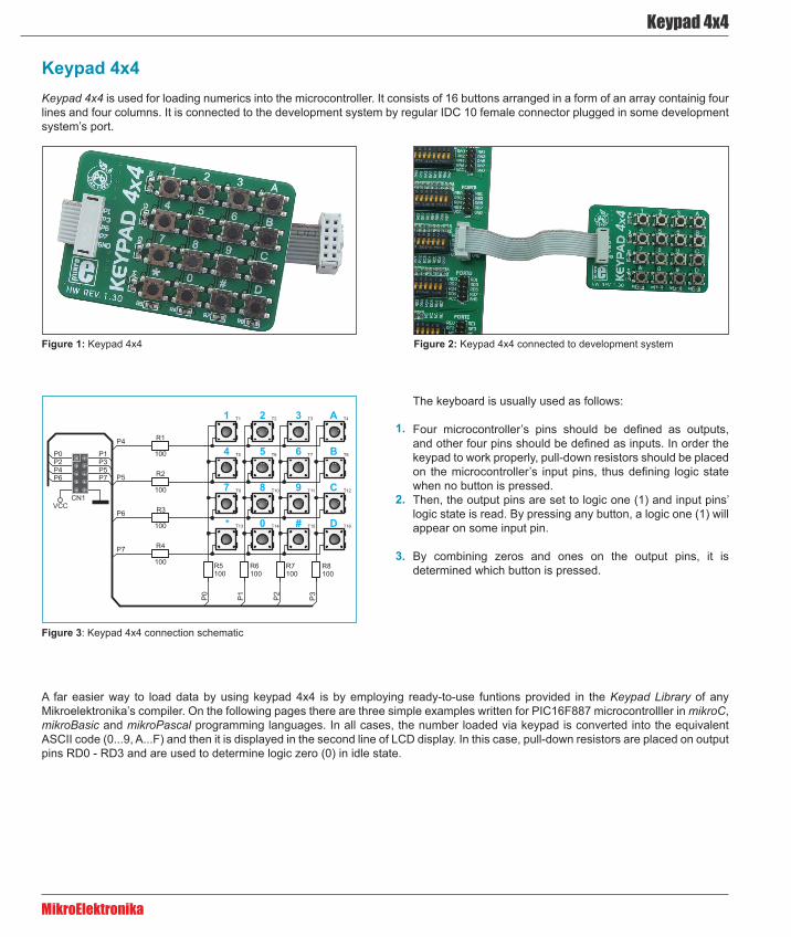
Keypad 4x4Keypad 4x4 is used for loading numerics into the microcontroller. It consists of 16 buttons arranged in a form of an array containig four lines and four columns. It is connected to the development system by regular IDC 10 female connector plugged in some development system’s port.
Figure 1: Keypad 4x4
Figure 3: Keypad 4x4 connection schematic
Figure 2: Keypad 4x4 connected to development system
A far easier way to load data by using keypad 4x4 is by employing ready-to-use funtions provided in the Keypad Library of any Mikroelektronika’s compiler. On the following pages there are three simple examples written for PIC16F887 microcontrolller in mikroC, mikroBasic and mikroPascal programming languages. In all cases, the number loaded via keypad is converted into the equivalent ASCII code (0...9, A...F) and then it is displayed in the second line of LCD display. In this case, pull-down resistors are placed on output pins RD0 - RD3 and are used to determine logic zero (0) in idle state.
The keyboard is usually used as follows:
Four microcontroller’s pins should be defined as outputs, and other four pins should be defined as inputs. In order the keypad to work properly, pull-down resistors should be placed on the microcontroller’s input pins, thus defining logic state when no button is pressed. Then, the output pins are set to logic one (1) and input pins’ logic state is read. By pressing any button, a logic one (1) will appear on some input pin.
By combining zeros and ones on the output pins, it is determined which button is pressed.
1.
2.
3.
Keypad 4x4
MikroElektronika
unsigned short kp, cnt, oldstate = 0;char txt[6];
// Keypad module connectionschar keypadPort at PORTD; // End Keypad module connections
sbit LCD_RS at RB4_bit; // LCD module connectionssbit LCD_EN at RB5_bit;sbit LCD_D4 at RB0_bit;sbit LCD_D5 at RB1_bit;sbit LCD_D6 at RB2_bit;sbit LCD_D7 at RB3_bit;
sbit LCD_RS_Direction at TRISB4_bit;sbit LCD_EN_Direction at TRISB5_bit;sbit LCD_D4_Direction at TRISB0_bit;sbit LCD_D5_Direction at TRISB1_bit;sbit LCD_D6_Direction at TRISB2_bit;sbit LCD_D7_Direction at TRISB3_bit; // End LCD module connections
void main() { cnt = 0; // Reset counter Keypad_Init(); // Initialize Keypad ANSEL = 0; // Configure AN pins as digital I/O ANSELH = 0; Lcd_Init(); // Initialize LCD Lcd_Cmd(_LCD_CLEAR); // Clear display Lcd_Cmd(_LCD_CURSOR_OFF); // Cursor off Lcd_Out(1, 1, “1”); Lcd_Out(1, 1, “Key :”); // Write message text on LCD Lcd_Out(2, 1, “Times:”);
do { kp = 0; // Reset key code variable
// Wait for key to be pressed and released do kp = Keypad_Key_Click(); // Store key code in kp variable while (!kp); // Prepare value for output, transform key to it’s ASCII value switch (kp) { //case 10: kp = 42; break; // ‘*’ // Uncomment this block for keypad4x3 //case 11: kp = 48; break; // ‘0’ //case 12: kp = 35; break; // ‘#’ //default: kp += 48;
case 1: kp = 49; break; // 1 // Uncomment this block for keypad4x4 case 2: kp = 50; break; // 2 case 3: kp = 51; break; // 3 case 4: kp = 65; break; // A case 5: kp = 52; break; // 4 case 6: kp = 53; break; // 5 case 7: kp = 54; break; // 6 case 8: kp = 66; break; // B case 9: kp = 55; break; // 7 case 10: kp = 56; break; // 8 case 11: kp = 57; break; // 9 case 12: kp = 67; break; // C case 13: kp = 42; break; // * case 14: kp = 48; break; // 0 case 15: kp = 35; break; // # case 16: kp = 68; break; // D }
if (kp != oldstate) { // Pressed key differs from previous cnt = 1; oldstate = kp; } else { // Pressed key is same as previous cnt++; }
Lcd_Chr(1, 10, kp); // Print key ASCII value on LCD
if (cnt == 255) { // If counter varialble overflow cnt = 0; Lcd_Out(2, 10, “ “); }
WordToStr(cnt, txt); // Transform counter value to string Lcd_Out(2, 10, txt); // Display counter value on LCD } while (1);}
Example 1: Program written in mikroC PRO for PIC
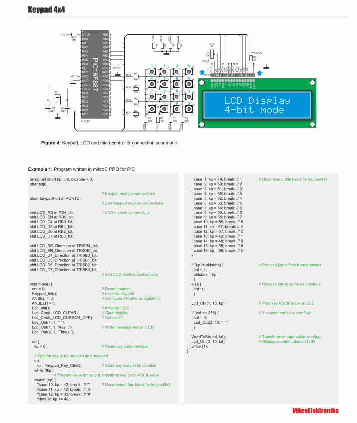
Figure 4: Keypad, LCD and microcontroller connection schematic
Keypad 4x4
MikroElektronika
program Keypad_Testdim kp, cnt, oldstate as byte txt as char[7]
‘ Keypad module connectionsdim keypadPort as byte at PORTD‘ End Keypad module connections
‘ Lcd module connectionsdim LCD_RS as sbit at RB4_bit LCD_EN as sbit at RB5_bit LCD_D4 as sbit at RB0_bit LCD_D5 as sbit at RB1_bit LCD_D6 as sbit at RB2_bit LCD_D7 as sbit at RB3_bit
LCD_RS_Direction as sbit at TRISB4_bit LCD_EN_Direction as sbit at TRISB5_bit LCD_D4_Direction as sbit at TRISB0_bit LCD_D5_Direction as sbit at TRISB1_bit LCD_D6_Direction as sbit at TRISB2_bit LCD_D7_Direction as sbit at TRISB3_bit‘ End Lcd module connections
main: oldstate = 0 cnt = 0 ‘ Reset counter Keypad_Init() ‘ Initialize Keypad ANSEL = 0 ‘ Configure AN pins as digital I/O ANSELH = 0 Lcd_Init() ‘ Initialize LCD Lcd_Cmd(_LCD_CLEAR) ‘ Clear display Lcd_Cmd(_LCD_CURSOR_OFF) ‘ Cursor off Lcd_Out(1, 1, “Key :”) ‘ Write message text on LCD Lcd_Out(2, 1, “Times:”)
while TRUE kp = 0 ‘ Reset key code variable
‘ Wait for key to be pressed and released while ( kp = 0 ) kp = Keypad_Key_Click() ‘ Store key code in kp variable wend ‘ Prepare value for output, transform key to it”s ASCII value select case kp ‘case 10: kp = 42 ‘ “*” ‘ Uncomment this block for keypad4x3 ‘case 11: kp = 48 ‘ “0” ‘case 12: kp = 35 ‘ “#” ‘default: kp += 48
case 1 kp = 49 ‘ 1 ‘ Uncomment this block for keypad4x4 case 2 kp = 50 ‘ 2 case 3 kp = 51 ‘ 3 case 4 kp = 65 ‘ A case 5 kp = 52 ‘ 4 case 6 kp = 53 ‘ 5 case 7 kp = 54 ‘ 6 case 8 kp = 66 ‘ B case 9 kp = 55 ‘ 7 case 10 kp = 56 ‘ 8 case 11 kp = 57 ‘ 9 case 12 kp = 67 ‘ C case 13 kp = 42 ‘ * case 14 kp = 48 ‘ 0 case 15 kp = 35 ‘ # case 16 kp = 68 ‘ D end select
if (kp <> oldstate) then ‘ Pressed key differs from previous cnt = 1 oldstate = kp else ‘ Pressed key is same as previous Inc(cnt) end if Lcd_Chr(1, 10, kp) ‘ Print key ASCII value on LCD
if (cnt = 255) then ‘ If counter varialble overflow cnt = 0 Lcd_Out(2, 10, “ “) end if
WordToStr(cnt, txt) ‘ Transform counter value to string Lcd_Out(2, 10, txt) ‘ Display counter value on LCD wendend.
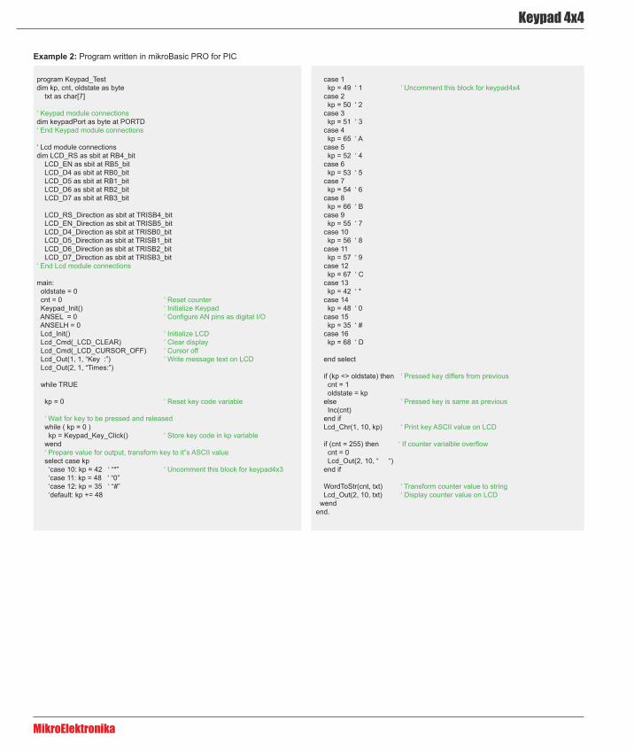
Example 2: Program written in mikroBasic PRO for PIC
Keypad 4x4
MikroElektronika
program Keypad_Test;
var kp, cnt, oldstate : byte; txt : array[6] of byte;
// Keypad module connectionsvar keypadPort : byte at PORTD;// End Keypad module connections
// Lcd module connectionsvar LCD_RS : sbit at RB4_bit; LCD_EN : sbit at RB5_bit; LCD_D4 : sbit at RB0_bit; LCD_D5 : sbit at RB1_bit; LCD_D6 : sbit at RB2_bit; LCD_D7 : sbit at RB3_bit;
var LCD_RS_Direction : sbit at TRISB4_bit; LCD_EN_Direction : sbit at TRISB5_bit; LCD_D4_Direction : sbit at TRISB0_bit; LCD_D5_Direction : sbit at TRISB1_bit; LCD_D6_Direction : sbit at TRISB2_bit; LCD_D7_Direction : sbit at TRISB3_bit;// End Lcd module connections
begin oldstate := 0; cnt := 0; // Reset counter Keypad_Init(); // Initialize Keypad ANSEL := 0; // Configure AN pins as digital I/O ANSELH := 0; Lcd_Init(); // Initialize Lcd Lcd_Cmd(_LCD_CLEAR); // Clear display Lcd_Cmd(_LCD_CURSOR_OFF); // Cursor off Lcd_Out(1, 1, ‘Key :’); // Write message text on Lcd Lcd_Out(2, 1, ‘Times:’);
while TRUE do begin kp := 0; // Reset key code variable
// Wait for key to be pressed and released while ( kp = 0 ) do kp := Keypad_Key_Click(); // Store key code in kp variable // Prepare value for output, transform key to it’s ASCII value case kp of //case 10: kp = 42; // ‘*’ // Uncomment this block for keypad4x3 //case 11: kp = 48; // ‘0’ //case 12: kp = 35; // ‘#’ //default: kp += 48;
1: kp := 49; // 1 // Uncomment this block for keypad4x4 2: kp := 50; // 2 3: kp := 51; // 3 4: kp := 65; // A 5: kp := 52; // 4 6: kp := 53; // 5 7: kp := 54; // 6 8: kp := 66; // B 9: kp := 55; // 7 10: kp := 56; // 8 11: kp := 57; // 9 12: kp := 67; // C 13: kp := 42; // * 14: kp := 48; // 0 15: kp := 35; // # 16: kp := 68; // D
end;
if (kp <> oldstate) then // Pressed key differs from previous begin cnt := 1; oldstate := kp; end else // Pressed key is same as previous Inc(cnt);
Lcd_Chr(1, 10, kp); // Print key ASCII value on Lcd
if (cnt = 255) then // If counter varialble overflow begin cnt := 0; Lcd_Out(2, 10, ‘ ‘); end;
WordToStr(cnt, txt); // Transform counter value to string
Lcd_Out(2, 10, txt); // Display counter value on Lcd end; end.
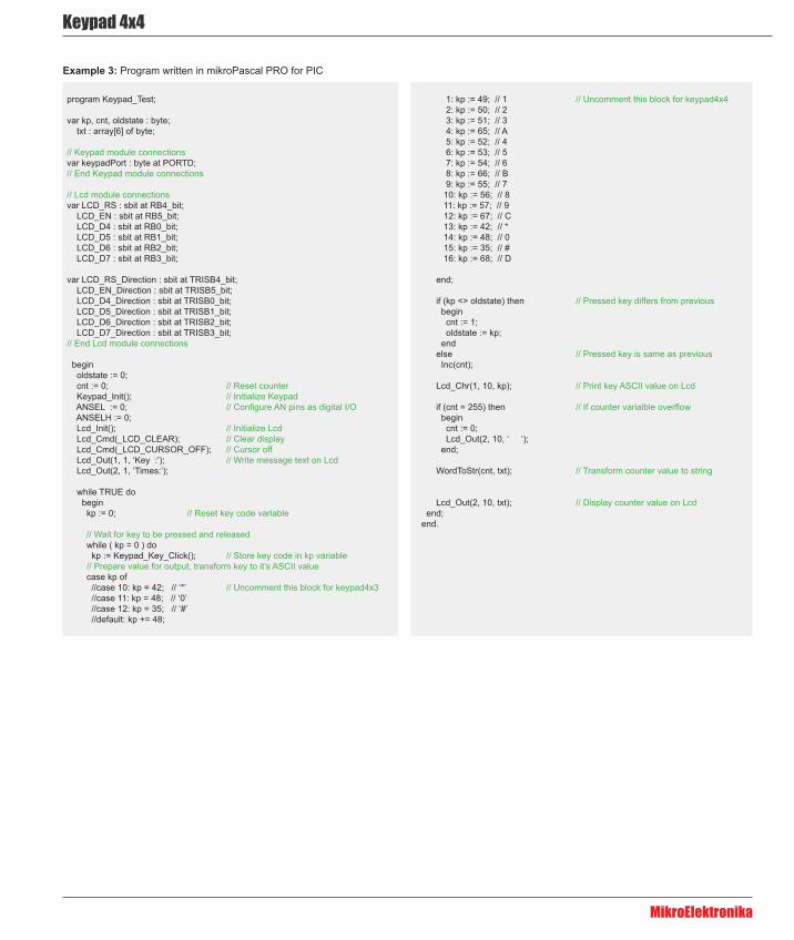
Example 3: Program written in mikroPascal PRO for PIC

PICPLC16 v6™
User manual
All MikroElektronika´s development systems represent irreplaceable tools for programming and developing microcontroller-based devices. Carefully chosen components and the use of machines of the last generation for mounting and testing thereof are the best guarantee of high reliability of our devices. Due to simple design, a large number of add-on modules and ready to use examples, all our users, regardless of their experience, have the possibility to develop their project in a fast and effi cient way.
Deve
lopm
ent S
yste
m
If yo
u w
ant t
o le
arn
mor
e ab
out o
ur p
rodu
cts,
ple
ase
visi
t our
web
site
at w
ww
.mik
roe.
com
If yo
u ar
e ex
perie
ncin
g so
me
prob
lem
s w
ith a
ny o
f our
pro
duct
s or
just
nee
d ad
ditio
nal i
nfor
mat
ion,
ple
ase
plac
e yo
ur ti
cket
at
ww
w.m
ikro
e.co
m/e
n/su
ppor
t
If yo
u ha
ve a
ny q
uest
ions
, com
men
ts o
r bus
ines
s pr
opos
als,
do
not h
esita
te to
con
tact
us
at o
ffi ce
@m
ikro
e.co
m