Jiejun Wang*, Fan Ning, Junzhu Li and Houyuan Zhu
11
132 Journal of Engineering Science and Technology Review 13 (4) (2020) 132 - 142 Research Article Experimental Study and Finite Element Simulation Analysis of the Bending Properties of Cross-Laminated Timber (CLT) Two-Way Plates Jiejun Wang*, Fan Ning, Junzhu Li and Houyuan Zhu School of Civil Engineering, Central South University of Forestry and Technology, Changsha 410004, Hunan, China Received 7 April 2020; Accepted 25 July 2020 ___________________________________________________________________________________________ Abstract Cross-laminated timber (CLT) plates are new components in modern wooden building structures and have good integrity, stability, and high strength. However, the bending performance of CLT plate is affected by the stacking method of laminates. This study adopted two different stacking methods (three-layer cross and four-layer cross) to make four CLT two-way slabs by using Larix gmelinii slab and polyurethane structural adhesive as raw materials. The slabs were divided into two groups to reveal the effects of stacking method on the bending performance of CLT two-way plates. A jack was used to apply concentrated load on a single point of the middle span of slabs, and the strain, deflection, and ultimate load data were measured. The crack development and failure mode were observed. The ultimate failure characteristics and failure mechanism were discussed, and the finite element model of CLT two-way slab was established using structural analysis software. The influence of elastic-plastic and plywood layers on the bending properties of CLT two-way slab was analyzed, and the results were compared with the experimental results. Results show that the failure modes of CLT two-way slabs are mainly from the transverse grain tensile failure of the slab bottom, and the bearing capacity decreases rapidly when the load reaches to approximately 80% of the ultimate load. For the same thickness of CLT plate, the flexural capacity of four-layer plate is increased by 14.08%, and the elastic bending stiffness is increased by 13.63% compared with three-layer plate. The overall bearing capacity and flexural stiffness of a two-way CLT slab with the same thickness can be improved by increasing the number of laminates when four sides are simply supported. The optimal number of laminates is five. The result of finite element simulation aligns with the test, showing that the test results and analysis are reliable. This study can provide references for future engineering design. Keywords: CLT two-way slab, Larix gmelinii, stacking method, bearing capacity, flexural rigidity, static load failure test, finite element simulation __________________________________________________________________________________________ 1. Introduction Compared with traditional building materials, glued laminated timber (glulam), as an ideal material of future construction, has advantages of environmental protection and sustainable development. Cross-laminated timber (CLT) is a prefabricated multilayer cross-laminated engineering wood product. It is made of at least three layers of sawn timber or structural composite panel by vertical orthogonal assembly and bonded with structural adhesive. Given that wood is an anisotropic material, CLT plates can reduce the effect of wood material properties on the mechanical properties of glulam components through orthogonal vertical stacking. This special stacking method enables CLT slabs to have superior overall mechanical and two-way mechanical properties. CLT slabs has many advantages, such as lightweight, high degree of prefabrication, and low cost, making them widely used in wood constructions, such as floors, wall members, shear walls, and bridge decks [1-2]. A two-way plate, where the ratio of the span from the long side to the short side is less than two, is a rectangular plate supported on four sides. Under vertical load, bending moments and bending deformation occur in longitudinal and horizontal directions. The characteristic of anisotropy makesthe design difficult, and many factors affecting the performance of the force, causing great challenges to study CLT plates. Scholars conducted a large number of studies with respect to the mechanical performance of CLT plates [3-11]. However, studies on the mechanical properties of CLT two-way plate are less, and studies on the influence of different stacking patterns on the mechanical properties of CLT two-way plate are rarely reported compared with the bending and shear properties of one-way plates. Therefore, identifying the bending properties of CLT two-way plate and clarifying the relationship between the mechanical properties of CLT two-way plate and different stacking methods are necessary. From the perspective of exploration and development of green building materials, this study applies a new type of engineering glulam product called orthogonal glulam to the bridge deck structure, which is a new product emerging in Europe and America in recent years, and proposes a CLT two-way slab component. The bearing capacity of CLT plate was analyzed, and the mechanical properties of CLT plate were explored through testing and finite element simulation analysis. The findings of this study promote the application of CLT plate in domestic wood bridge structure and construction engineering and provide a reference for engineering design. JOURNAL OF Engineering Science and Technology Review www.jestr.org Jestr r ______________ *E-mail address: [email protected] ISSN: 1791-2377 © 2020 School of Science, IHU. All rights reserved. doi:10.25103/jestr.134.13
Transcript of Jiejun Wang*, Fan Ning, Junzhu Li and Houyuan Zhu

132
Journal of Engineering Science and Technology Review 13 (4) (2020) 132 - 142
Research Article
Experimental Study and Finite Element Simulation Analysis of the Bending Properties
of Cross-Laminated Timber (CLT) Two-Way Plates
Jiejun Wang*, Fan Ning, Junzhu Li and Houyuan Zhu
School of Civil Engineering, Central South University of Forestry and Technology, Changsha 410004, Hunan, China
Received 7 April 2020; Accepted 25 July 2020 ___________________________________________________________________________________________ Abstract
Cross-laminated timber (CLT) plates are new components in modern wooden building structures and have good integrity, stability, and high strength. However, the bending performance of CLT plate is affected by the stacking method of laminates. This study adopted two different stacking methods (three-layer cross and four-layer cross) to make four CLT two-way slabs by using Larix gmelinii slab and polyurethane structural adhesive as raw materials. The slabs were divided into two groups to reveal the effects of stacking method on the bending performance of CLT two-way plates. A jack was used to apply concentrated load on a single point of the middle span of slabs, and the strain, deflection, and ultimate load data were measured. The crack development and failure mode were observed. The ultimate failure characteristics and failure mechanism were discussed, and the finite element model of CLT two-way slab was established using structural analysis software. The influence of elastic-plastic and plywood layers on the bending properties of CLT two-way slab was analyzed, and the results were compared with the experimental results. Results show that the failure modes of CLT two-way slabs are mainly from the transverse grain tensile failure of the slab bottom, and the bearing capacity decreases rapidly when the load reaches to approximately 80% of the ultimate load. For the same thickness of CLT plate, the flexural capacity of four-layer plate is increased by 14.08%, and the elastic bending stiffness is increased by 13.63% compared with three-layer plate. The overall bearing capacity and flexural stiffness of a two-way CLT slab with the same thickness can be improved by increasing the number of laminates when four sides are simply supported. The optimal number of laminates is five. The result of finite element simulation aligns with the test, showing that the test results and analysis are reliable. This study can provide references for future engineering design. Keywords: CLT two-way slab, Larix gmelinii, stacking method, bearing capacity, flexural rigidity, static load failure test, finite element simulation __________________________________________________________________________________________
1. Introduction Compared with traditional building materials, glued laminated timber (glulam), as an ideal material of future construction, has advantages of environmental protection and sustainable development. Cross-laminated timber (CLT) is a prefabricated multilayer cross-laminated engineering wood product. It is made of at least three layers of sawn timber or structural composite panel by vertical orthogonal assembly and bonded with structural adhesive. Given that wood is an anisotropic material, CLT plates can reduce the effect of wood material properties on the mechanical properties of glulam components through orthogonal vertical stacking. This special stacking method enables CLT slabs to have superior overall mechanical and two-way mechanical properties. CLT slabs has many advantages, such as lightweight, high degree of prefabrication, and low cost, making them widely used in wood constructions, such as floors, wall members, shear walls, and bridge decks [1-2].
A two-way plate, where the ratio of the span from the long side to the short side is less than two, is a rectangular plate supported on four sides. Under vertical load, bending moments and bending deformation occur in longitudinal and
horizontal directions. The characteristic of anisotropy makesthe design difficult, and many factors affecting the performance of the force, causing great challenges to study CLT plates. Scholars conducted a large number of studies with respect to the mechanical performance of CLT plates [3-11]. However, studies on the mechanical properties of CLT two-way plate are less, and studies on the influence of different stacking patterns on the mechanical properties of CLT two-way plate are rarely reported compared with the bending and shear properties of one-way plates. Therefore, identifying the bending properties of CLT two-way plate and clarifying the relationship between the mechanical properties of CLT two-way plate and different stacking methods are necessary.
From the perspective of exploration and development of green building materials, this study applies a new type of engineering glulam product called orthogonal glulam to the bridge deck structure, which is a new product emerging in Europe and America in recent years, and proposes a CLT two-way slab component. The bearing capacity of CLT plate was analyzed, and the mechanical properties of CLT plate were explored through testing and finite element simulation analysis. The findings of this study promote the application of CLT plate in domestic wood bridge structure and construction engineering and provide a reference for engineering design.
JOURNAL OF Engineering Science and Technology Review
www.jestr.org
Jestr
r
______________ *E-mail address: [email protected] ISSN: 1791-2377 © 2020 School of Science, IHU. All rights reserved. doi:10.25103/jestr.134.13

Jiejun Wang, Fan Ning, Junzhu Li and Houyuan Zhu/Journal of Engineering Science and Technology Review 13 (4) (2020) 132 - 142
133
2. State-of-the-art Scholars have conducted many studies on the structural performance of CLT plates. I. Gavric, M et al. studied the veneer and CLT wall panels with different types of anchoring systems and different types of joints between adjacent panels and established a nonlinear pushover analytical model of the CLT wall system. They found that the layout and design of nodes and the number of screws at the vertical connection between adjacent wall panels are crucial to the overall performance of the structural system. However, the proposed analytical model can only describe the performance of the 2D CLT wall system [6]. Davids et al. investigated the bending and shear properties of a three-layer CLT slab with a mixture of Spruce-pine-fir (SPF) and laminated strand lumber (LSL). The results showed that the shear resistance of CLT plate can be enhanced by increasing the interlayer strength. However, only low-grade materials are used to make the panel, and the results are inapplicable to the panel made of high-grade LSL or SPF materials. The tested samples are made of continuous plates rather than the finger joint plate, which is common in the industry. Therefore, the reduction in tensile capacity of finger joint to plate is not considered [7]. Sikora et al. explored the bending and shear properties of CLT plates with different thickness. The results showed that the bending and shear strengths decrease with the increase in plate thickness. However, whether this conclusion is applicable to CLT plates made of wood from other tree species needs further verification [8]. L. Franzoni et al. analyzed the influence of wood interlayer gap on the elastic properties of CLT slab through modeling and experiment. However, the proposed periodic homogenization method must use finite element software to solve the problem, thereby limiting its realization in practical applications [9]. G. Hochreiner et al. conducted a bending performance test on CLT plate and evaluated its failure mechanism and failure mode occurring inside the plate to determine the failure mechanism and internal failure of CLT plates; however, the layer of CLT plate was ignored [10]. Houri Sharifnia et al. designed experiments to study the influence of process parameters on the mechanical properties of CLT and obtained the best manufacturing parameters. However, they did not explore the influence mechanism of various parameters on the mechanical properties of CLT plates [11]. Van de Lindt et al. explored the seismic performance of CLT walls and panels with several aspect ratios to study the seismic performance of CLT structures. However, the sliding of the panel with an aspect ratio of 2.1:1 in stage 3.2 is caused by nail shear failure in the bottom shear bracket. Therefore, whether the ratio between the length and width of panel has a sliding mechanism as its failure model cannot be concluded [12]. Sato m et al. conducted an experimental study on the seismic behavior of a five-story building with CLT walls and high ductility ties. The results showed that the bottom of shear wall is only damaged by compression under the action of MS7 (Japanese standard) earthquake. Although the interlaminar shear capacity of CLT wall calculated by numerical model and element test, such as connectors, passed the safety assessment, further study about the unit and system level is needed to correctly evaluate the bearing capacity [13].
Xie W B, Lu Y et al. [14-17] used CLT plates made of western Canadian hemlock as raw materials to conduct relevant tests and analysis on the mechanical properties and durability of the main strength direction. However, imported wood was used in the study, which is unfavorable for the
development of domestic wood manufacturing with CLT plate technology. The variability of shear strength, wood breakage rate, and delamination rate of adhesive layer cannot be well controlled due to the lack of in-depth study on wood anisotropy. Y. Lu et al. [18] obtained the interlaminar shear stresses of CLT plates with three, five, and seven ply gluing layers based on Hooke’s law and the mechanical relationship between the bending moment and shear stress of beams. The results showed that the interlaminar and maximum shear stresses of CLT plates are related to the number of gluing layers and to the ratio of elastic modulus of parallel and vertical layers. M. He et al. [19] conducted experimental tests on the external bending and compressive properties of hemlock spruce CLT plate and obtained its basic mechanical properties in the primary and secondary directions. However, the modulus of elasticity (MOE) value of CLT panel estimated from the strain–stress relationship is slightly less than the equivalent MOE value calculated in accordance with the CLT design manual. The nonlinear behavior of CLT specimens in the secondary strength direction observed on the load-deflection curve is not studied due to the gap between the loaded steel plate and the specimen. Gong Yingchun et al. used a three-point loading method to explore the influence of elastic modulus, number of layers, laminate thickness, and direction of sawn lumber assembly on the interlaminar shear performance of CLT plates. The results showed that the interlaminar shear performance of CLT can be significantly improved by changing the texture direction of the blank, and the equivalent shear stiffness of CLT can be effectively predicted using the shear analogy method [27].
Scholars worldwide mostly focus on the application of CLT slab in housing construction and CLT one-way slab, and the exploration and application of CLT member in bridge structures are rare. This study adopted an orthogonal glulam two-way slab, which is theoretically suitable for engineering applications, by considering the two-way bending characteristics of bridge deck and the anisotropic characteristics of wood. The proposed slab was used to enhance the structural integrity of timber bridge, reduce its structural vibration and deformation, improve the utilization rate of wood, and reduce the cost,. The deck was glued to the web of a T- section beam, which can avoid the shortcomings of traditional wood bridge structure, such as stress concentration caused by nailing, rivet corrosion, and loosening, to improve the structural durability. The experimental and theoretical studies on the flexural bearing capacity of glulam T-section beams were completed [20]. In this study, Larix gmelinii was used as raw material, and a new type of water-based polyurethane adhesive was used for bonding. Two groups of CLT two-way plate specimens were made using different assembly methods. The bending performance, failure mechanism, and the influence of the forming method on the bending property of CLT two-way plate were discussed through testing and finite element simulation analysis. This study provided a reference for engineering design.
The remainder of this study is organized as follows. Section 3 introduces the material properties, design dimensions, loading device, and measurement scheme of the component. Section 4 describes the failure mode and failure mechanism of the member, and analyzes the load-deflection and load-strain curves in detail. A CLT two-way board model is established on ABAQUS finite element software, and the influence of deflection deformation, stress, and strain of the model, and the number of plywood layers on its

Jiejun Wang, Fan Ning, Junzhu Li and Houyuan Zhu/Journal of Engineering Science and Technology Review 13 (4) (2020) 132 - 142
134
deflection and stiffness is analyzed. Section 5 summarizes the whole study, provides the relevant conclusions, and discusses the problems to be solved in the future. 3 Methodology 3.1 Component materials and design Two groups of four CLT two-way panels were designed. The specimens were glued with polyurethane structural adhesive to ensure that the bonding strength was higher than the tensile strength along the grain and transverse grain of wood. During the processing, the sawn timber was visually graded to ensure that the strength of each specimen was basically the same. The physical and mechanical properties of wood can be found in the material property test [21-23]. The mechanical property parameters are shown in Table 1,
and the mechanical property parameters of structural adhesive are provided by the manufacturer.
Group A (two pieces): four layers of plates with the same thickness were glued vertically in accordance with the grain lines, indicating that the grain directions of the upper and lower layers and the middle layer plates (2 layers) were perpendicular to each other. Group B (two pieces): three layers of boards with the same thickness were glued vertically in accordance with the grain pattern. Specifically, the direction of the wood grain of the upper and lower layers was perpendicular to the middle layer. The sizes of the two groups of specimens were 1200 mm × 1 200 mm × 80 mm, as shown in Fig. 1. The moisture content of wood was determined in accordance with the “method for determining the moisture content of wood” [24], and the average moisture content of this batch of wood was 13.53%.
Table 1. Physical and mechanical properties of materials
Material Initial density (g/cm3)
Water content (%)
Tensile strength parallel to grain
(MPa)
Tensile strength perpendicular to
grain (MPa)
Flexural strength (MPa)
Elastic modulus (MPa)
L. gmelinii 0.67 13.53 129.03 5.94 86.23 10 140 Polyurethane structural
adhesive 1.50 - ≥40 ≥75 - ≥3 500
(a) Group A test piece
(b) Group B test piece
Fig. 1. Specimen structure (mm) 3.2 Loading and measurement plan The main test parameters included vertical deflection deformation, ultimate load, and mid span section strain of the two groups of specimens under vertical concentrated load. The test was conducted at the Civil Engineering Structure Laboratory of Central South University of Forestry and Technology. I-shaped steel beams were used to make a four-sided supporting frame, and a 2 cm-thick rubber plate was placed between the top surface of the supporting beam and the CLT plate to support the four sides of the glulam
two-way plate (Fig. 2 (c)). In the test, step loading was adopted under concentrated load. A 50 t pressure sensor was set on the top of the jack to control the applied load at each stage. The strain data of the specimen were collected synchronously with a TST3826 static strain test system. Two transverse and longitudinal strain gauges were set at the transverse and longitudinal directions of L/4, L/2 and L/4 (L is the plate span) on the bottom surface of the specimen, with a total of 10 strain measuring points to test the deformation. A displacement meter was placed at the center of the bottom plate to measure the vertical displacement in the middle span of the two-way slab. Figures 2 shows the specific loading device, strain gauge number, and the arrangement of measuring points of the displacement meter.
A leveling ruler was used to adjust the flatness of the plate surface in the preparation stage to ensure the uniform stress of the two-way slab in the test. The loading and center points of the plate surface were aligned before loading to ensure they coincide. Before the test, the specimen was preloaded with 5 kN (lasting for 2 minutes) and unloaded to 0 kN. The purpose of preloading was to eliminate the bad contact between the specimen and the bearing and make the initial reading value of 10 strain gauges differ within 5%.
(a) Schematic of plate top loading (mm)

Jiejun Wang, Fan Ning, Junzhu Li and Houyuan Zhu/Journal of Engineering Science and Technology Review 13 (4) (2020) 132 - 142
135
(b) Arrangement of strain measuring points at the bottom of the plate
(mm)
(c) Actual loading diagram
Fig. 2. Views of test equipment and measuring points 4 Result Analysis and Discussion 4.1 Failure mode and mechanism analysis In the test, the failure of the two groups of glulam two-way slabs was similar (Fig. 3). At the initial loading stage, the two groups of CLT two-way slabs were in the elastic stage. The two-way slabs exhibited crisp sounds, and a small number of small cracks began to appear in the transverse direction near the middle span of the slab bottom surface when the load increased to 90% of the ultimate load. With continuous increase in load, the small cracks at the bottom of the plate continued to expand and gradually developed to cracks. Frequent low sound occurred in this process. The specimens exhibited a sudden huge splitting sound, the crack at the bottom of the plate expanded rapidly and then to two. The two groups of specimens were bent and damaged when the load reached the bearing limit. This condition was caused by the tensile failure of the transverse grain at the bottom of the plate. During the test, no cracks and degumming were found on the bonding surface between adjacent laminates and transverse plates.
Mechanism analysis: the failure modes of the two groups of orthogonal glulam two-way slabs under concentrated load in the middle of the span belong to the typical transverse grain tensile failure at the bottom of the slab. In this test, the CLT plate is a two-way slab supported on four sides, and the length and width (span) are the same. The maximum bending moment values of the two-way slab in the longitudinal and transverse directions are the same under concentrated load in the middle of the span. However, the tensile strength along the grain direction is high, and the
tensile strength in the transverse direction is low. Thus, the bottom surface of the plate is damaged by transverse tension.
(a) A1
(b) A2
(c) B1
(d) B2
Fig. 3. Failure modes of CLT two-way slab
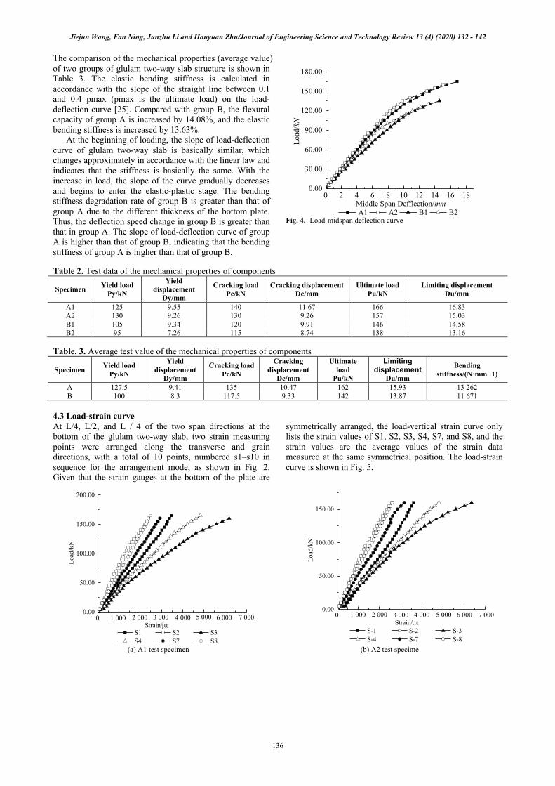
4.2 Load-deflection curve The load-deflection curve and mechanical property test data of each specimen are shown in Fig. 4 and Table 2 respectively. As shown in Figure 4, the bearing capacity of group A members is greater than that of group B members.
Jiejun Wang, Fan Ning, Junzhu Li and Houyuan Zhu/Journal of Engineering Science and Technology Review 13 (4) (2020) 132 - 142
136
The comparison of the mechanical properties (average value) of two groups of glulam two-way slab structure is shown in Table 3. The elastic bending stiffness is calculated in accordance with the slope of the straight line between 0.1 and 0.4 pmax (pmax is the ultimate load) on the load-deflection curve [25]. Compared with group B, the flexural capacity of group A is increased by 14.08%, and the elastic bending stiffness is increased by 13.63%.
At the beginning of loading, the slope of load-deflection curve of glulam two-way slab is basically similar, which changes approximately in accordance with the linear law and indicates that the stiffness is basically the same. With the increase in load, the slope of the curve gradually decreases and begins to enter the elastic-plastic stage. The bending stiffness degradation rate of group B is greater than that of group A due to the different thickness of the bottom plate. Thus, the deflection speed change in group B is greater than that in group A. The slope of load-deflection curve of group A is higher than that of group B, indicating that the bending stiffness of group A is higher than that of group B.
Fig. 4. Load-midspan deflection curve
Table 2. Test data of the mechanical properties of components
Specimen Yield load Py/kN
Yield displacement
Dy/mm
Cracking load Pc/kN
Cracking displacement Dc/mm
Ultimate load Pu/kN
Limiting displacement Du/mm
A1 125 9.55 140 11.67 166 16.83 A2 130 9.26 130 9.26 157 15.03 B1 105 9.34 120 9.91 146 14.58 B2 95 7.26 115 8.74 138 13.16
Table. 3. Average test value of the mechanical properties of components
Specimen Yield load Py/kN
Yield displacement
Dy/mm
Cracking load Pc/kN
Cracking displacement
Dc/mm
Ultimate load
Pu/kN
Limiting displacement
Du/mm
Bending stiffness/(N·mm−1)
A 127.5 9.41 135 10.47 162 15.93 13 262 B 100 8.3 117.5 9.33 142 13.87 11 671
4.3 Load-strain curve
At L/4, L/2, and L / 4 of the two span directions at the bottom of the glulam two-way slab, two strain measuring points were arranged along the transverse and grain directions, with a total of 10 points, numbered s1–s10 in sequence for the arrangement mode, as shown in Fig. 2. Given that the strain gauges at the bottom of the plate are
symmetrically arranged, the load-vertical strain curve only lists the strain values of S1, S2, S3, S4, S7, and S8, and the strain values are the average values of the strain data measured at the same symmetrical position. The load-strain curve is shown in Fig. 5.
(a) A1 test specimen
(b) A2 test specime
A1 A2 B1 B2
0.00
30.00
60.00
90.00
120.00
150.00
180.00
0 2 4 6 8 10 12 14 16 18 Middle Span Defflection/mm
Load
/kN
0.00
50.00
100.00
150.00
200.00
7 0006 0005 0004 0003 0002 000
S1 S2 S3 S4 S7 S8
Loa
d/kN
Strain/µe0 1 000
0.00
50.00
100.00
150.00
7 0006 0005 0004 0003 0002 0001 000 Strain/µe
Loa
d/kN
S-1 S-2 S-3 S-4 S-7 S-8
0

Jiejun Wang, Fan Ning, Junzhu Li and Houyuan Zhu/Journal of Engineering Science and Technology Review 13 (4) (2020) 132 - 142
137
(c) B1 test specimen
(d) B2 test specimen
Fig. 5. Load-strain curve
By analyzing the load-average strain curves of the three specimens in Fig. 5, the following conclusions can be drawn.
1) As shown in Fig. 5, the strain values at each measuring point on the bottom plate of the test piece increase with the increase in load, and the change in strain shows a similar law on the whole. The strain of the transverse and parallel lines at the midspan position of the bottom plate is the largest, and the nonlinear strain of the middle span section is greater than that of the L/4 and 3L/4 sections. The change in strain value at each measuring point and the difference in strain in the midspan section of each specimen are small when the initial load is small. With the increase in load, the corresponding growth rate and difference increase at the same time. In the elastic stage, the slope of the strain curve is close to each other, showing a linear relationship. With the increase in load, the specimen transits from elastic stage to elastic-plastic stage, and the slope of curve decreases until the specimen reaches the peak load. With the increase in deformation, the bearing capacity decreases rapidly, and the middle span deformation increases. The transverse grain is damaged, and the two-way slab loses bearing capacity.
2) In the bending process, the strain of group A (four-layer plate) is less than that of group B (three-layer plate) until the specimen reaches the peak load. This finding indicates that increasing the number of bonding layers of the two-way slab improves its bearing capacity under the same thickness. This condition is because increasing the number of gluing layers improves the uniformity of the mechanical properties of CLT plate in transverse and longitudinal directions, thereby improving the overall bearing capacity of the plate.
4.4 Finite element analysis of CLT two-way plate 4.4.1 Establishment of finite element model The finite element model of CLT two-way slab was established on ABAQUS software in accordance with the size of the specimen. The wood density was 0.67 g/cm3. The material direction of CLT laminate was set by assigning material direction. Binding constraint simulation was adopted because no degumming and sliding were found between the laminates. A steel plate was used under the loading sensor on the top of the plate. The mass density of the steel was 7.8 g/cm3, the elastic modulus was 2.1 × 10⁵ MPa, and the Poisson’s ratio was 0.3. The steel strength was relatively large, and the elastic deformation was ignored. A
reference point (RP-1) was defined at the upper part of the center, and the reference point was coupled with the steel plate to simulate the loading conditions. The supporting condition of CLT plate was simply supported on four sides. The loads of three-layer and four-layer plates were 132 and 162 kN, respectively. The load increased linearly with time. The accuracy and calculation time of the numerical simulation results depended on the number of grids. The CLT plate was meshed, and the grid size was 5 cm in accordance with the accuracy and time requirements. The wood along the grain direction was set as the X axis, the transverse direction was set as the y axis, and the height direction of the board was set as the Z axis, as shown in Figure 6.
(a) Three-layer plate
(b) Four-layer plate
Fig. 6. CLT bidirectional plate finite element model In this study, an ideal elastoplastic constitutive model
(Fig. 7) was adopted. Its expression is shown in Equation (1).
0.00
50.00
100.00
150.00
6 0004 0002 000Strain/µe
Load
/kN
S1 S2 S3 S4 S7 S8
00.00
50.00
100.00
150.00
7 0006 0005 0004 0003 0002 0001 000 Strain/µe
Loa
d/kN
S-1 S-2 S-3 S-4 S-7 S-8
0

Jiejun Wang, Fan Ning, Junzhu Li and Houyuan Zhu/Journal of Engineering Science and Technology Review 13 (4) (2020) 132 - 142
138
(1)
where
—Stress of the wood; E—Elastic modulus of wood;
—Strain of wood; is the yield compressive stress, and is the yield
tensile stress; , , , and are the yield compressive, yield
tensile, ultimate compressive, and ultimate tensile strains, respectively.
The MOE values along the grain, radial and tangential
elastic moduli, shear modulus, and Poisson’s ratio of wood were determined according to reference [20] [26] due to the
lack of sufficient test data. The specific material properties are shown in Table 4.
Fig. 7. Ideal elastoplastic constitutive relation
Table 3. Physical and mechanical properties of materials Engineering elastic constant
Elastic modulus (MPa) Poisson’s ratio Shear modulus (MPa) E1 E2 E3
Numerical value 16 900 1 690 845 0.36 0.48 0.53 1 268 1 014 304 4.4.2 Deformation of CLT two-way plate
The deflection finite element nephogram of CLT two-way slab is shown in Fig. 8. The comparison of load-deflection curves between the test and finite element simulation of A1
member in group A and B1 member in group B is shown in Fig. 9.
(a) Three-layer plate
(b) Four-layer plate
Fig. 8. Deformation diagram of glued timber beam (unit: mm)
Fig. 9. Comparison of load-midspan deflection curves between the test and simulation
As shown in Fig. 8, the maximum deflection of CLT plate under the action of ultimate load occurs at the middle span position and gradually decreases toward the support side. As shown in Fig. 9, the variation law of the deflection curve between the finite element simulation analysis and the test is basically consistent. The value difference between the analysis and the test is small, and the simulated deflection is less than the measured deflection. Although the actual components have knot defects, they are not considered when establishing the finite element model. The mechanical parameters of wood are imperfect, and certain errors occur in the actual operation due to the experimental conditions, lead to certain differences between the two. The results of finite element simulation are in good agreement with the measured results.
4.4.3 Stress and strain of CLT two-way plate In accordance with the test results, the failure mode of CLT two-way slab under the middle span with ultimate load was
c0 t0
cu c0 cu
tu t0 tu
E=
e e e es s e e e
s e e e
£ £ìï £ £íï £ £î
!
s
ecus tus
c0e t0e cue tue
12n 13n 23n 12G 13G 23G
0
50
100
150
200
0 5 10 15Midlle span defflection f/mm
Load
F/k
N
Test valua of group A Simulated valuas of group A Test valua of group B Simulated valuas of group B

Jiejun Wang, Fan Ning, Junzhu Li and Houyuan Zhu/Journal of Engineering Science and Technology Review 13 (4) (2020) 132 - 142
139
transverse tensile failure, and the tensile and compressive strains along the grain did not reach the ultimate strain. Therefore, analyzing the stress and strain in the transverse direction of the CLT two-way plate is necessary. The transverse stress and strain nephogram at the bottom plate of the two-way plate are shown in Figs. 10 and 11, respectively.
As shown in Fig. 10, an unfavorable area with approximate elliptical crossing-striated tensile stress is generated near the middle span of the slab bottom when the two-way slab specimen is subjected to failure load, which is similar to the actual failure area of the test component. The failure location does not appear in the span center of the bottom plate because the stress is concentrated around the bottom edge of the steel plate during loading. The tensile stress of the transverse grain gradually decreases in a stepwise manner to the surroundings. The maximum transverse tensile stress of the three-layer and four-layer plates are 6.24 and 8.05 MPa, respectively, which are greater than the experimental values of transverse tensile strength of L. gmelinii (5.94 MPa). Therefore, the tensile stress in the transverse direction is the main reason for the transverse tensile failure at the bottom of the two-way plate. The initial crack occurs at approximately 80% of the ultimate failure load. With the increase in load, the initial crack extended rapidly and finally formed a straight joint. Before the CLT plate is damaged, the sound of wood tearing is low and dense, and the bearing capacity is completely lost after a huge tearing sound
The two groups of specimens have relatively large local stress under the loading steel plate, which is consistent with the large wood compression deformation at the contact between the board and the steel plate in the actual test.
(a) Three-layer plate
(b) Four-layer plate
Fig. 10. Longitudinal tensile stress nephogram under failure load (unit: MPa)
As shown in Fig. 11, the maximum transverse tensile strain on the bottom of CLT plate is symmetrically distributed near the middle of the span, which is basically consistent with the transverse tensile failure position of the test results. The maximum transverse tensile strains at the bottom surface of the three-layer and four-layer plates are 8.94 and 6.93 × 10⁻³ ε, respectively. The transverse tensile strain of the three-layer plate is larger than that of the four-layer plate. This finding is consistent with the characteristic where the deflection of the three-layer plate is greater than that of the four-layer plate. The maximum compressive strain occurs at the corner of the loaded steel plate, which is −2.27 and −1.67 × 10⁻² ε, respectively, which is consistent with the compression deformation in the loading area. The ultimate tensile strain of wood is 0.005–0.006 ε, and the ultimate compressive strain is 0.010–0.012ε, which decreases with the increase in specimen size. In this study, the transverse tensile strain on the tensile side of the specimen is slightly larger than the above value. This condition is because the plate is still working when a small crack occurs at the bottom, thereby making the limit strain of simulation analysis larger than the general limit strain value of wood.
(a) Three-layer plate
(b) Four-layer plate
Fig. 11. Cloud diagram of horizontal grain tension strain of the floor under failure load
4.4.4 Effect of plywood layers on the bending deflection and stiffness of CLT two-way plate Six members with different layers and fixed thickness (80 mm) are selected for finite element simulation analysis. The cross-section assembly method is shown in Fig. 12. The same size and boundary conditions (simply supported on four sides) are used in the calculation to facilitate comparison, and only the deflection in the elastic stage is compared and analyzed. The applied load is 70% of the test limit load of the four-layer plate, and the loading value is 90

Jiejun Wang, Fan Ning, Junzhu Li and Houyuan Zhu/Journal of Engineering Science and Technology Review 13 (4) (2020) 132 - 142
140
kN. The ratio of load to deflection in the elastic stage is defined as the elastic stiffness. The deflection and elastic stiffness obtained by analysis are shown in Fig. 13. For the CLT two-way slabs with the same thickness, the maximum deflection at the midspan decreases and the stiffness increases with the increase in the number of gluing layers. This finding indicates that the more the glued layers are, the more uniform the mechanical properties of the components are. The stiffness increases evidently when the number of layers changes from three to five. However, the change speed in stiffness decreases when the number of laminates is more than five. The change in stiffness stabilizes when the number of laminates is more than seven, indicating that excessive glued layers have no evident effect on the stiffness improvement of the plate. The best bonding layer is five in terms of the mechanical properties and processing factors.
(a) Three-layer plate
(b) Four-layer plate
(c) Five-layer plate
(d) Six-layer plate
(e) Seven-layer plate
(f) Eight-layer plate
Fig. 12. Stacking mode of CLT
(a) Deflection curve
(b) Stiffness curve
Fig. 13. Deflection and elastic stiffness curves 5. Conclusions In this study, the influence of assembly pattern on the bending performance of CLT two-way board and the method to improve the bearing capacity of traditional wood components were explored. The load-deflection characteristics, load-strain relationship, and failure mechanism of CLT two-way plates were analyzed through bending bearing capacity test and finite element simulation. The conclusions are summarized as follows:
(1) Under the condition of supported four sides, the two groups of glulam two-way plates are subjected to concentrated load. During bending, the transverse grain tensile failure occurs at the bottom of the plate. Before the failure, cracks and sounds appear at the bottom of the plate, and the failure mode is brittle failure. Compared with the three-layer CLT plate, the flexural capacity and flexural stiffness of four-layer CLT plate are increased by 14.08% and 13.63%, respectively. The results show that the bearing capacity and stiffness of four-layer CLT plate are greater than that of three-layer CLT plate under the same thickness.
(2) The load-strain curve of the tensile side at the bottom is elastic plastic, and the transverse strain in the middle of the span is greater than that in the longitudinal direction.
(3) The deflection curves of finite element simulation analysis and test are basically consistent. The difference between the analysis and the test values is small, and the simulated deflection is less than the deflection measured by the test. An unfavorable area with approximate elliptical crossing-striated tensile stress appears near the middle span of the slab bottom when the two-way slab is subjected to failure load, which is close to the actual failure area of the test component. The tensile stress of the transverse grain gradually decreases in a stepwise manner to the surroundings. The maximum transverse tensile stress at the bottom of the plate is greater than the experimental values of transverse tensile strength of L. gmelinii. Therefore, the tensile stress in the transverse direction is the main reason for the transverse tensile failure at the bottom of the two-way plate. The maximum transverse tensile strain at the bottom of the three-layer plate is larger than that of the four-layer plate. This condition is consistent with the phenomenon that the deflection of the three-layer plate is greater than that of the four-layer plate.
(4) For the CLT two-way plates with the same thickness, the middle span deflection decreases, and the bending
2 4 6 8
5.0
5.5
6.0
Mid
span
def
lect
ion(
mm
)
Number of adhesive layers
2 4 6 8
12000
13000
14000
15000
Elas
tic st
iffne
ss(
N·m
m-1)
Number of adhesive layers

Jiejun Wang, Fan Ning, Junzhu Li and Houyuan Zhu/Journal of Engineering Science and Technology Review 13 (4) (2020) 132 - 142
141
stiffness increases under the vertical load with the increase in the number of glued layers. This finding indicates that the more the glued layers are, the more uniform the mechanical properties and the greater the bending stiffness are. The optimal number of gluing layers is five in terms of the bending stiffness and processing factors of CLT two-way plate.
In this study, the bearing capacity of CLT two-way slab was studied through experiment and finite element simulation analysis. The main failure feature of CLT two-way slab under concentrated load in the middle span was tensile failure at the bottom of the slab under concentrated load on four sides. No debonding and cracking were found on the joint surface of plywood. For the same thickness of CLT board, the bearing capacity and elastic bending stiffness of four-layer CLT board were greater than that of three-layer CLT board. This finding indicated that the forming method influences the bearing capacity and bending stiffness of CLT board. Finite element simulation analysis was conducted, and the variation rule of bending stiffness of the CLT two-way plate with the same thickness changing with the number of glued layers was verified. These results
provide theoretical and engineering values and are innovation points of this study.
Following topics should be focused in the future study: conducting further experimental and theoretical studies; developing the calculation method and empirical formula for the bending bearing capacity of orthogonal Glulam CLT two-way slab; exploring the bearing capacity of CLT two-way slab under different boundary conditions; and clarifying the bearing capacity of CLT two-way slab under different supporting conditions to facilitate its engineering application. Acknowledgements This work was supported by the International S&T Cooperation Program of China (Grant No. 2014DFA53120) and the Special Research Program for Public Welfare Forestry of China (Grant No. 201304504-3). This is an Open Access article distributed under the terms of the Creative Commons Attribution License
______________________________
References 1. Cao, Y., Wang, Y. L., Wang Z., Wang, J. H., “Application and
research progress of overseas of cross-laminated timber(CLT) construction”. China Forest Products Industry, 43(12), 2016, pp. 3-7.
2. Liu, W. Q., Yang, H. F., “Research progress on modern timber structures”. Journal of Building Structures, 40(2), 2019, pp. 16-43.
3. Zhou, Q. Y., Gong, M., Chui, Y. H., Mohammad Mohammad., “Measurement of rolling shear modulus and strength of cross-laminated timber fabricated with black spruce”.Construction and Building Materials, 64(30),2014,pp.379-386.
4. E.I. Saavedra Flores, I. Dayyani, R.M. Ajaj, R. Castro-Triguero, F.A. DiazDelaO, R. Das, P. González Soto, “Analysis of cross-laminated timber by computational homogenization and experimental validation”. Composite Structures, 121, 2015, pp .386-394.
5. Frangi, A., Fontana, M., Hugi, E., Jübstl, R., “Experimental analysis of cross-laminated timber panels in fire”. Fire Safety Journal, 44(8), 2009, pp. 1078–1087.
6. Gavric, I., Fragiacomo, M., Ceccotti, A., “Cyclic Behavior of CLT Wall Systems: Experimental Tests and Analytical Prediction Models”. Journal of Structural Engineering, 141(11), 2015, pp. 04015034.
7. Davids, W. G., Willey, N., Lopez-Anido, R., Shaler, S., Gardner, D., Edgar, R., & Tajvidi, M. “Structural performance of hybrid SPFs-LSL cross-laminated timber panels”.Construction and Building Materials, 149,2017,pp.156-163.
8. Sikora, K. S., McPolin, D. O., & Harte, A. M., “Effects of the thickness of cross-laminated timber (CLT) panels made from Irish Sitka spruce on mechanical performance in bending and shear”. Construction and Building Materials, 116, 2016, pp .141-150.
9. Franzoni, L., Lebée, A., Lyon, F., Forêt, G., “Elastic behavior of Cross Laminated Timber and timber panels with regular gaps: Thick-plate modeling and experimental validation”. Engineering Structures, 141, 2017, pp.402-416
10. Hochreiner, G., Füssl, J., Eberhardsteiner, J., “Cross-laminated timber plates subjected to concentrated loading experimental identification of failure mechanisms ”. Strain, 50(1), 2013, pp.68-81.
11. Houri Sharifnia, Daniel P.Hindman., “Effect of manufacturing parameters on mechanical properties of southern yellow pine cross laminated timbers”. Construction and Building Materials, 156, 2017, pp.314-320.
12. Van de Lindt, J. W., Furley, J., Amini, M. O., Pei, S., Tamagnone, G., Barbosa, A. R., Popovski, M., “Experimental seismic behavior of a two-story CLT platform building”. Engineering Structures, 183, 2019, pp.408-422.
13. Sato, M., Isoda, H., Araki, Y., Nakagawa, T., Kawai, N., Miyake, T., “A seismic behavior and numerical model of narrow paneled cross-laminated timber building”. Engineering Structures, 179(3), 2019, pp. 9-22.
14. Xie, W. B., Wang, Z., Gao, Z. Z., Wang, J. H., “Performance test and analysis of orthogonal Glulam (CLT)”. Forest products industry, 45 (10), 2018, pp. 40-45, 49.
15. Lu, Y., Li, M. M., Wang, Z., Gao, Z. Z., Wang, J. H., “Calculation and analysis of mechanical properties of three-layer hemlock plywood structure”. Journal of Northwest Forestry University, 33 (6), 2018, pp. 231-235
16. Li, M. M., Xie, W. B., Wang, Z., Gao, Z. Z., “Dynamic measurement and stress classification of elastic modulus of cross glued hemlock hemlock lumber”. Forestry industry, 45 (7), 2018, pp. 28-32.
17. Wang, Y. L, Cao, Y., Wang, Z., Gao, Z. Z., Wang, J. H., “Prediction and evaluation of bending properties of normal Glulam of Tsuga canadensis”. Forest products industry, 44 (7), 2017, pp. 15-20.
18. Lu, Y., Xie, W. B., Wang, Z., Gao, Z. Z., “Shear stress and inter laminar shear strength tests of cross-laminated timber beams”. Bioresources, 13(3), 2018, pp. 5343-5359.
19. HE, M, SUN, X, LI, Z., “Bending and compressive properties of cross-laminated timber (CLT) panels made from Canadian hemlock”. Construction and Building Materials, 185, 2018, pp.175-183.
20. Wang, J. J, Yang, T., Ning, F., Rao, Z. Y., “Bending Capacity of Orthogonal and Parallel Glulam T-section Beams”. Journal of Engineering Science and Technology Review, 13 (1), 2020, pp.86-97.
21. General Administration of Quality Supervision, Inspection and Quarantine of the People's Republic of China, Standardization Administration of China, GB /T 1938-2009., “Method of testing in tensile parallel to grain of wood”. Beijing: China Quality Inspection Press, 2009.
22. General Administration of Quality Supervision, Inspection and Quarantine of the People's Republic of China, Standardization Administration of China, GB/T1936.2-2009., “Method for determination of the modulus of elasticity in static bending of wood”. Beijing: China Quality Inspection Press, 2009.
23 General Administration of Quality Supervision, Inspection and Quarantine of the People's Republic of China, Standardization Administration of China, GB /T 1936.1-2009., “Method of testing in bending strength of wood”. Beijing: China Quality Inspection Press, 2009.

Jiejun Wang, Fan Ning, Junzhu Li and Houyuan Zhu/Journal of Engineering Science and Technology Review 13 (4) (2020) 132 - 142
142
24. General Administration of Quality Supervision, Inspection and Quarantine of the People's Republic of China, Standardization Administration of China, GB /T 1931-2009., “Method for determination of moisture content of wood”. Beijing: China Quality Inspection Press, 2009.
25. Shi, Y., Zhou, X. H., Song, K., Liu, J. “Study on bending stiffness of cold-formed thin-walled steel beam OSB plate composite floor”. Journal of Architectural Science and engineering, 32 (5), 2015, pp. 50-57
26. Long, W.G., Yang, X. B., “Wood structure design manual (Third Edition)”. Beijing: China Construction Industry Press, China, 2005.
27. Gong, Y. C., Xu, J. H., Wu, G. F., Ren, H. Q., “Interlaminar shear properties of Japanese Larch normal Glulam”. Wood industry, 32 (2), 2018, pp.6-9.