Distillation Column Flooding Diagnostics with Intelligent Differential Pressure Transmitter

1 IP2020Nov 00
Instructionm
anualIP
2020
Installation, operation andmaintenance instructions
JERGUSON Intelligent DisplacerLevel Transmitter

2 IP2020Nov 00
CONTENTSCONTENTS
Page
1.0 OVERVIEW1.1 Use 51.2 Basic operation 51.3 Calibration 51.4 Take care ! 5
2.0 UNPACKING & INSTALLATION (Mechanical)2.1 Unpacking 72.2 Mounting arrangements 72.3 Level Transmitter assembly 72.4 Transmitter range 92.5 Mounting on the vessel 92.6 Securing the LVDT cap 11
3.0 ELECTRICAL CONNECTION 133.1 Power Supply 133.2 Cable type and length 143.3 Cable gland 143.4 Connection 143.5 Safety Barriers 143.6 Lightning protection 153.7 Multi-drop installations 153.8 Final checks
4.0 COMMISSIONING4.1 In-Situ commissioning 164.2 Local calibration adjustments at operating conditions 16
Zero, Span and Re-ranging 16Damping 17Customisation Using a SMART communicator 17
4.3 Adjustments to accommodate changes in process operating conditions 18
5.0 FAULT-FINDING5.1 No output 205.2 Incorrect output 205.3 Display Module - Error messages 21
6.0 MAINTENANCE6.1 Routine Maintenance 226.2 Spares 22
7.0 CK1 HANDHELD SMART COMMUNICATOR7.1 Calibration adjustments at operating conditions 237.2 Further customisation using the SMART communicator 247.3 Adjustments to accomdate changes in process conditions using a SMART HHC 25

3 IP2020Nov 00
APPENDICES
A Model code information 26B Bolting torque details 27C Bench calibration 28D Handheld Communicator CK* 31D1.0 HHC Assembly 31D.2.0. Notes 31D.3.0. Requirements for SMART operation 33D.4.0. How to connect the SMART communicator 33D.5.0. HHC - Operation 34D.6.0. Intrinsically safe SMART communicator 34D.7.0. How to drive az Psion based SMART communicator 35D.8.0. Introduction and FUNCTION menu 39D.9.0. Keyboard Functions 42D.10.0. Parameter List 43D.11.0. Parameter Descriptions 45D.12.0. Using the Non-linear profile facility 57D.13.0. Safe, working, offline, default Registers 63D.14.0. Error messages on the HHC 68D.15.0. Current loop checks and trimming 71D.16.0. Multidrop or Bus Operation 73D17.0 . Unknown Instrument 76D.18.0. SMART Interface - Compatibility 77E Block diagram / flowchart 78
FIGURES
Fig I Main Components 6Fig II Pressure tube assembly 6Fig III Level transmitter components 8Fig IV Supporting the displacer element before mounting the head assembly 8Fig V Securing the LVDT cap 10Fig VI Transmitter head with cover removed 12Fig VII Load .v. Voltage 13Fig VIII Temperature graphs 19
Fig D1 CK*HHC assembly 3 0Fig DII Loop Diagram 32Fig DIII PSION HHC menu str ucture 38 & 40Fig DIV Linear vessel or sump 58Fig DVFig DVI Memory Locations in Smart Communicator 64Fig DVII Off Line memory transfers 66Fig EI Block diagram / Flowchart 78

4 IP2020Nov 00
The Displacement Level Transmitter

5 IP2020Nov 00
1.0. OVERVIEW
1.1 Use: The Displacer Level Transmitter type will transmit a 4 – 20mA signal proportional toliquid level or interface position over a simple 2 wire 24v dc power loop. The instrument is installed eitherdirectly on the top of the vessel or in an external chamber, valved to the main vessel, such that the displacerelement is immersed in the liquid.
DT Series may be installed in a hazardous area. There are two designs of DT Series; one I.S. foruse in a suitable I.S. circuit, and one Flameproof/Explosionproof, suitable for connection to suitable stopperglands and conduit. Always refer to the installation requirements stated on the enclosed certificates forspecific installation instructions. DT Series may, of course, be used in a non-hazardous area, where any localwiring requirements apply.
1.2 Basic operation : The displacer, which is normally partially-immersed in the process fluid, is suspendedfrom an extension spring. The effective weight on this spring changes as the level of the process liquid risesand falls on the displacer. This is predictable and depends upon the density of the liquid and the diameter ofthe displacer. In turn the extension of the suspension spring will change as the weight suspended from itchanges. The core of an LVDT (Linear Variable Differential Transformer) is attached to the moving partssuspended from the spring, and moves up and down in the pressure tube of the transmitter enclosure. AnLVDT is positioned on the pressure tube in the enclosure. The positional changes of the core in relation tothe LVDT will cause electrical changes which are interpreted by the transmitter electronics as changes ofliquid level.
1.3 Calibration : Each DT Series is factory calibrated to give optimum performance in the application conditionsadvised at the time of order. Provided these conditions have not changed, the instrument will give accuratereadings of level at operating pressure, temperature and SG. Refer to sections 4 & 5 for details of re-calibration if this is necessary.
1.4 Take care ! : The DT Series is an instrument, and should be handled with due care and attention at all times.Mounting flanges can be heavy and difficult to handle. It is particularly important that the DT Series is notdamaged when installing on the vessel or chamber, and that the Installation instructions in section 2 arecarefully followed.
Thank you for choosing a Displacement level transmitter – correct installation and use will result inmany years of trouble free operation.
PLEASE NOW READ THE RELEVANT SECTIONS OF THIS MANUAL.
Footnote :- In this manual the following terms are used which refer to trademarks from other manufacturers:
HART: is the protocol adopted for the DT Series SMART Communications.HART is a registered trademark of the HART Communications Foundation and is a mnemonic ForHighway Addressable Remote Transducer.
PSION: is the trade mark of PSION plc who manufacture the PSION ORGANISERHand held computer. The SMART program is stored in a DATAPAK which is also atrademark of PSION plc, and is an accessory for the Model LZ Organiser

6 IP2020Nov 00
Fig I : DT Series - main components
Fig II : Pressure tube assembly
100mm Standard version321mm H.T. version

7 IP2020Nov 00
2.0 UNPACKING & INSTALLATION
2.1 UnpackingThe unit is supplied in three parts, usually in two packages. The larger package contains the control head andspring/rod assembly. A second package contains the displacement element. Any mounting flange orchamber will be packaged separately. Refer to Fig I.
After unpacking the control head check that the model code / Tag Number is the one expected for thisapplication (refer to Appendix A for model code explanation). Note that the head, the spring assembly andthe displacer element are a matched set. Components must not be mixed and matched between transmitters.Each will be marked with the unique transmitter Final Assembly Number for identification.
If there are any queries, please refer to your local Agent , quoting the transmitterFinal Assembly Number and our order reference.
2.2 Mounting arrangements
2.2.1 External Chamber Mounting Transmitters.If a chamber has been supplied, unpack and remove any packing or tie strings. Ensure that the chamber iscompletely clean and fit to the mating vessel connections. The chamber should be mounted within 1.5 deg. tothe vertical, and the top flange should be checked with a spirit level to see it is horizontal.Sometimes, when the DT Series is used on a chamber, there is not enough space above the upper liquid levelfor its moving parts. In these situations an extension in the form of a stand pipe will have been supplied, andthis should now be fitted to the chamber using a suitable gasket or seal, ensuring once again that the topflange is horizontal.
2.2.2. Direct Mounting Transmitters.
2.2.2.1 Stilling tubes.If there is a high degree of agitation in the vessel, such that the displacer element could be caused to swing orbounce, then a stilling tube should be installed in the vessel. Ensure that the stilling tube has an internaldiameter large enough to allow free movement of the displacer element, and that a vent hole is drilled at thetop to prevent air-locks. The tube must be installed vertically so that the displacer element does not touch thetube at any point.
2.2.2.2 Stand OffSometimes, when the DT Series is used on a vessel, there is not enough space above the upper liquid level forits moving parts. In these situations an extension in the form of a stand pipe will have been supplied, and thisshould now be fitted to the vessel using a suitable gasket or seal, ensuring that the top flange is horizontal.
2.3 Level transmitter assembly.
IMPORTANT NOTES.It is strongly recommended that two people work together at this stage, particularly when installingthe instrument on the vessel.Take great care not to bend the rod at any stage of installation. A bent rod will prevent yourDT Series from working.Do not slacken any of the lock nuts on the rod assembly; these have all be present for yourapplication.
When unpacked, the enclosure will be free to rotate on the pressure tube assembly. This is to allow correctorientation of the enclosure, conduit entry and display (if fitted) after installation. High pressure transmitterswill have been supplied with the head factory fitted and secured in the mounting flange. If a flange issupplied separately, you should now screw the head into the mounting flange using a suitable thread sealant,using the hexagon to tighten and effect the pressure seal. The thread is 1” NPT taper.
Next, fit the spring and rod assembly to the head. Make sure that the core, rod, and anti-friction sleeve arefree from any dirt or pieces of packing material. Remove any seal from the bottom of the pressure tubeassembly and gently pass the core into the pressure tube assembly. Carefully feed the rod into the tube,avoiding the step reduction in diameter of the internal bore of the tube. (See Fig II).
Once inserted, check that the rod moves freely in the pressure tube, then screw the top of the upper springcarrier onto the thread at the foot of the pressure tube. Assemble finger tight, then lock in position bytightening the 3mm grub screw using a 1.5mm hexagonal key. (See Fig III)
The head assembly is now complete and no other adjustments need be made at this stage.Your transmitter has already been factory calibrated for use at the operating conditions stated at thetime of order. Decide now if you wish to bench check the calibration of your transmitter at 20C, in whichcase refer to Appendix C or if you want to mount your transmitter on the vessel and check calibration atoperating conditions, in which case please read on.

8 IP2020Nov 00
LOCKINGTABS
SPLIT PIN
Fig III : Level transmitter components
Fig IV : Supporting the displacer elementbefore mounting the head assembly.

9 IP2020Nov 00
2.4 Checking the position of the transmitter range. (normal liquid application, not interface applications)
Before you mount the transmitter assembly into the vessel you may wish to check that the displacer element ishanging at the correct level below the transmitter head.
Attach the chain at the top of the displacer element (See Fig.III) to the end of the spring rod using the splitpin provided. Locate the split pin in the third link down from the rod so that you have two unused links freeat the top. (Do not remove these free links or fully bend the pin legs at this time as you may need to removeor re-position the displacer again later).
With the displacer element hanging in free air at 20C and the spring extended by the weight of the displacer,measure the distance from the sealing face of the mounting flange to the bottom of the displacer, which iscalled the “free hanging distance”. Include the thickness of any seals or gaskets.
This is the approximate distance below the sealing face of the flange which is factory calibrated to give a4mA output from the transmitter in a normal level application, unless you requested otherwise at the time oforder. You can re-range later if you require – see Section 4.0. For interface applications it is not possible tocheck the 4mA point without the upper liquid present.
Check that this dimension is correct to your requirements, ±5mm, particularly if you are mounting thetransmitter on a chamber. In this case, the dimension should be equal to the dimension from the chambermounting flange sealing face to the centre line of the bottom process connection bore, or around 30mm fromthe bottom of the chamber for a side/bottom connection chamber.
There is some mechanical adjustment possible of the position of the displacer element below the top flange :+/- 25mm. If the error is within this band, locate the small length (typically 5 links) of chain on which thedisplacer element is suspended and adjust the number of links to correct the error. Do not cut any surpluslinks from the chain. If the error is greater than ±25mm, refer to Magne-Sonic for assistance.
2.5 Mounting the transmitter on the vessel or chamber.
If you attached the displacer to the head as above, it is best to now disconnect the displacer from the rod,leaving the chain attached to the displacer. Ensure that the chain is securely fixed to the displacer, checkingthat the locknut is tight.
Lower the displacer into the vessel and slip the 5mm diameter support rod through the lowest link of thechain so that the weight of the displacer is taken by the rod and the vessel mounting flange. See Fig.IV.
Remember that the enclosure is still free to rotate on the pressure tube at this stage.
Ensure a suitable gasket or seal is fitted to the mating flange and, holding the head vertical, attach the bottomof the rod to the chain coupling. Bend the split pin legs to effect a permanent fixing. Taking the weight ofthe displacer by hand, carefully withdraw the support rod and allow the displacer element to extend thespring, lowering the element into the vessel. Do not allow the displacer weight to fall freely and damage thespring.
Check that the displacer element does not foul on any part of the chamber or vessel.Locate the transmitter flange on the mating flange so that the cable entry and display (if fitted) are facing theway you require.
Fit the flange bolts and tighten to the recommended torque (see Appendix B) to achieve a pressure seal.Check that the pressure tube is sufficiently tightened into the top flange, using the hexagons on the pressuretube.
Rotate the enclosure to the exact position required and strike the tabs of the locking tab washer (see Fig.III)under the enclosure base onto the hexagon flats of the pressure tube to prevent further rotation of theenclosure on the pressure tube.

10 IP2020Nov 00
Fig V : Securing the LVDT cap

11 IP2020Nov 00
2.6 Securing the LVDT cap
The LVDT cap inside the enclosure leaves the factory free to rotate on the LVDT so that movement intransit and during installation is not transmitted to the LVDT. The LVDT cap must now be secured inposition. (See Fig. V).
If the cover is in place, locate and unscrew the cover locking grub screw and unscrew the cover from thebase.
Locate and tighten the LVDT locknut at the top of the pressure tube against the top of the LVDT cap sothat it can no longer rotate on the LVDT. Remove the transit tape from the LVDT.
Refer now to wiring section or, if the transmitter is to be left in this condition for a period, check that thecover seal is in good condition and re-fit the cover, then secure cover locking screw. Check any conduits aresuitably sealed against ingress of moisture.

12 IP2020Nov 00
Fig VI : Transmitter head with cover removed.

13 IP2020Nov 00
3.0 ELECTRICAL CONNECTION
The DT Series is a 2-wire dc loop-powered transmitter and requires a 24v dc nominal power supply.Note that it is the responsibility of the installer to observe all local regulations and approval requirements, andto use materials to suit the environmental conditions of the particular application. Check and obtain anyhazardous area work permits before applying power to the DT Series.
If you DT Series has been supplied with a Display module, note that you do not need to remove the cover ofthe display for wiring. All field wiring is connected in the main head enclosure.
If the head cover is in place, locate and unscrew the cover locking grub screw and unscrew the cover fromthe base.
Fig VI shows the layout inside the transmitter with the cover removed.A terminal block is provided for power supply and screen connection, together with a pair of 2mm socketsfor connection of an ammeter to monitor the loop current.There are 2 small sockets integrated into the terminal block for convenient connection of a HandheldCommunicator if required. (Use only an I.S. approved communicator if in a Hazardous area).The small target and LED’s are used for bench calibration of the transmitter if required – refer to Section 4.0
Whilst the cover is removed, ensure that the 2 multi-way plugs are not disturbed in their sockets. (The plugswill have been secured in their sockets at the factory with a sealing compound).
3.1 Power Supply
3.1.1. Operating voltageThe DT Series will work satisfactorily provided the voltage at the transmitter terminals remains between 12and 40V dc.In considering the voltage of the power supply, allowance must be made for the voltage drop across any loadin series with the transmitter such as an indicator or the cable itself. The largest voltage drop will occur at themaximum current which is 21mA under alarm conditions. See Fig.VII for a Load v Voltage graph whichdefines the acceptable range of power supply voltages for any given installation.
Fig.VII : Load .v. Voltage
3.1.2. Special Considerations for HARTIf the HART communications facility built into the transmitter will be used at the time of installation orduring its future working life, then it is essential that a resistive load of at least 250 Ohms is connected in thesupply cable. This may be provided by other devices in the loop (Chart recorder, meter, etc.) or more usuallyby installing a standard 270 Ohm 0.25W resistor in series with transmitter at the power supply. In this way themaster device will be able to signal to the transmitter without the power supply short-circuiting the data.
3.2 Cable type and length.
The cable should be single twisted pair shielded or multiple twisted pair with each pair shielded and an overallshield to BS5308 or equivalent.The terminal block will accept wire size up to 2.5mm2 (xzxSWG, 14AWG). It is recommended that theminimum conductor size should be 1.0mm2 up to 5000ft total length and 20 AWG above 5000 ft., but theuser should always ensure that the voltage at the terminals is a minimum of 12v dc.
14 IP2020Nov 00
3.2.1 Cable Capacitance
When used in Hazardous areas in an Intrinsically Safe circuit, refer to the Approval Pack supplied with thistransmitter for details of the maximum cable capacitance allowed.
3.2.2 Special considerations for HART
In addition, excessive cable capacitance will attenuate the HART signalling and so the capacitance mustanyway be limited if HART communications is to be used. The RC time constant for the network must notexceed 650µs, e.g. if the network resistance is, say, 650W then the maximum network capacitance is 0.1µF.HART transmitters are often given a Cn number where n is the multiple of 5000pF which the device presentsto the network. In the case of DT Series the value of n is 1 since its capacitance is well below 5000pF.
3.2.3. Total loop resistance and capacitance
Additional equipment such as indicators or recorders may be inserted in the loop subject to the resistance andcapacitance limits discussed above.
3.2.4. Multi-core cables
In multi-pair installations it is important that the other pairs do not interfere with the HART signalling – theyshould only be used for other HART loops or for purely analogue signals.
3.2.5. Cable trays
It is recommended that HART signal cables are not run alongside power cables.
3.3 Cable Gland
The cable gland entry thread is 1” NPT female – the enclosure is rated IP66 and so a suitable combination ofgland and cable should be selected. When used in a hazardous area, glands must comply with the relevantIntrinsically Safe or Flameproof/Explosionproof requirements.
3.4 Connection
Connection of the supply cable is to the + and – terminals with the cable screen being connected to the ‘scn’terminal. The cable screen should normally be earthed at the power supply end.
An external earth point is also provided.
3.5 Safety Barriers
In the case of passive barriers, allowance must be made for the additional voltage drop across the barrieritself.Care should be exercised in selecting a barrier or isolator especially if it will be necessary to pass HARTcommunications through the device.
Typical barriers are manufactured by :-MTLStahlPepperl & FuchsElconABB
3.6 Lightning Protection
If local conditions dictate, it is recommended that a lightning suppresser is fitted. A typical manufacturer isTelematic who can supply products suitable for IS as well as non-IS installations.

15 IP2020Nov 00
3.7 Multi-drop installations ( DT Series in HART digital mode)
Up to 15 transmitters (unless in an I.S. loop – see below) may be connected in parallel with each other, andeach must be set to a different HART address between 1 and 15 (see Section vv). When HART transmittersare connected in multi-drop mode, each transmitter draws a fixed current of 4mA, and allowance must bemade for the total maximum current that could be drawn (15 x 4mA = 60mA)
3.7.1. Compatibility with other HART instruments.
Any 2-wire HART transmitter, regardless of the manufacturer, may be simply connected in parallel withanother to create a mutli-drop network. They may also be combined with separately powered, currentsourcing or sinking devices but care must be taken to ensure that the HART signal current passes through the250W minimum impedance to establish communications. For full details of HART instrument availability,refer to the HART Foundation publications or individual manufacturers literature.
3.7.2. Intrinsically safe installations.
In multi-drop IS installations, typically a maximum of 5 transmitters may be connected to the loop in parallel,thus limiting the current in the loop.
3.7.3. Handheld Communicators
A handheld communicator (HHC) may be connected across the network (downstream of the minimum 250Ohm loop resistance) to programme or interrogate a HART transmitter. Somme HHC’s support only asubset of a transmitter’s functions, and will thus only access the transmitters Universal and Common Practicecommands. However, the DT Series is fully supportedby the Magne-Sonic CK!1 HHC and by the UNIVERSAL275 HHC (provided the 275 is loaded with the transmitter’s Device Description – contact Magne-Sonic orthe HART Communications Foundation for details).
3.8 Final checks.
When all wiring is complete, check that the two multi-way plugs remain securely in their respective sockets.
Check that the cable gland is tightened into the conduit and a good seal is formed. If the transmitter is to becommissioned at this point, refer now to Section 4.0. If not, check that the cover seal is in good condition,then replace the cover and screw down fully to ensure the weatherproof rating of the enclosure ismaintained. (Do not attempt to overtighten as the torque you apply to the cover will be transmitted to thepressure tube union and locking tab washer; these must not be loosened by overtightening of the cover).Tighten the cover locking grub screw.
16 IP2020Nov 00
4.0 COMMISSIONING
Your DT Series transmitter has been supplied calibrated to the requirements of the specific application advisedat the time of ordering. You should now refer to the Set-up Certificate supplied with the transmitter to checkthis data is still valid.If you wish to carry out some bench calibration or testing, refer now to Appendix C
4.1 In-Situ Commissioning
Important note : Some of the adjustments described below require the DT Series cover to be removed withpower on. Check and obtain any hazardous area work permits required before removing the cover.
4.1.2. Initial power up
Turn on the power and check that the “Heartbeat” LED in the Caliplug beats at about once every 3 seconds.If your transmitter is fitted with a display module, the display will show the software revision number (in theformat *.*), then change to show the measured value.
With the displacer element hanging on the spring and rod assembly, the displacer spring will be extended dueto the weight of the element hanging on it.Your transmitter has been calibrated to give an accurate 4 – 20mA output proportional to level at a specificset of operating conditions : SG, pressure and temperature. When experiencing these operating conditions,the spring will behave differently to it’s normal performance in air at 20C, so the transmitter output at 20Cmay not be as you expect.The current output can be displayed on a milliameter connected at the two sockets provided or on theHHC. However, if your transmitter has been calibrated for operation at temperatures above ambient,you are likely to see higher values than this as the spring will be stiffer at 20C than at the operatingtemperature, and hence the core is sitting higher in the LVDT coil. Once operating conditions are reached,the spring will relax and the core will drop, giving an output of 4mA with the vessel empty.
4.2 Local calibration adjustments at operating conditions.
Once the vessel has reached process operating conditions, the following can be checked and adjusted ifrequired :-
If you wish to fine tune the 4 and 20mA points or to re-range the transmitter to give the 4-20mA output overa different span, this can now be done. Note, the 4mA point can be positioned above the 20mA point toreverse the operation of the transmitter, thus giving a falling current output with rising liquid level.To maintain accuracy, it is recommended that the maximum turndown used is 3:1.
Zero level – 4mA point. With no liquid in the vessel, the output should be 4mA.If the output is within 3.9 and 4.1mA, refer to 4.2.1 below to fine tune to exactly 4mA. If the output withthe vessel empty and at operating conditions is outside of these limits, it is likely that the position of theLVDT in the transmitter head needs to be adjusted. Refer to Appendix C “LVDT Setting” before makingany further adjustments.
High level – 20mA point. This occurs with the displacer element almost fully covered with liquid (to within10-15mm of the top of the parallel portion of the element), and the output should be 20mA.
These adjustments may be made locally with the Magnetic Scroller (MMS) and the Caliplug on thetransmitter (See Section 4.2.1. overleaf) , or may be made either locally or remotely using a SMARTCommunicator (HHC) connected across the two wire loop. (For details of adjustments using the HHC, refernow to Section 7.0).

17 IP2020Nov 00
4.2.1. Local calibration using the Magnetic Scroller (MMS) and the Caliplug with the transmitter atoperating pressure, temperature and SG.
4mA point : With the vessel empty or the liquid at the level required for 4mA output, insert the magnetic tipof the MMS into the Caliplug port marked “Z”. Hold in until acceptance of the new setting is given by theCaliplug LDD flashing at an increased rate of twice per second.
20mA point : With the liquid at the level required for 20mA output, insert the magnetic tip of the MMS intothe Caliplug port marked “S”. Hold in until acceptance of the new setting is given by the Caliplug LEDflashing at an increased rate of twice per second.
Ranging with a partially full vessel : If it is not possible to fill the vessel to the required 20mA level, thetransmitter can be ranged in a partially full vessel.With liquid in the vessel at a level above the 4mA level, the current output can be incremented to a value thatrepresents this level. For example, with the vessel ¾ full, the current would be set at a value of 16mA.Connect a milliammeter at the two sockets inside the enclosure.To enter the ranging mode, hold the MMS on the small target icon on the internal nameplate for about 3seconds. One (or both) of the 2 LED’s adjacent to the target icon will start to flash. Insert the magnetic tipof the MMS into the “S” port of the Caliplug to increase the current out as shown on the milliammeter, orthe “Z” port to decrease the current at this level. Withdraw the MMS once the current level has been set tothe required level.Hold the MMS on the target again to deactivate the LED’s and exit the ranging mode. Note, the instrumentwill automatically exit the ranging mode if left for longer than 5 minutes.
Damping : The damping of the transmitter may be adjusted using the MMS and the Caliplug. The dampingvalue entered is actually a time constant in seconds which is applied as smoothing to the level reading and theoutput current. A new value may be entered up to a value of 100 seconds. A large value will have the effectof smoothing out rapid changes of level and will also smooth out the effects of turbulence. (It would behighly unusual to select a value greater than 30 seconds.)Insert the magnetic tip of the MMS into the “T” port of the Caliplug and hold in place for a number ofseconds equivalent to the damping that you require, noting that the LED flash rate increases to once persecond during setting of damping. Once the MMS is removed, the new damping value is set.
Your DT Series is now ready to operate.
Finally check all seals and conduits are in good condition and replace the transmitter head cover and securewith the locking grub screw.
If you experience any unusual output or apparently faulty operation of your DT Series, refer to Section 4.3“Adjustments to accommodate changes in process operating conditions and Section 5.0 “Fault finding”.

18 IP2020Nov 00
4.3 Adjustments to accommodate changes in process operating conditions
It may be that actual process conditions are a little different to those envisaged at time of order and used toset-up you DT Series.
Your DT Series has been factory set to give you the correct output under the operating conditions which youquoted in your enquiry/order. If you intend to operate outside the parameters for which the DT Series hasbeen factory set, please read the notes below. These describe a variety of deviations and their implications.Typical deviations are:
a. More dense process liquid.b. Less dense process liquid.c. More dense upper liquid/gas.d. Less dense upper liquid/gas.e. Higher process temperature.f. Lower process temperature.g. The range is in the wrong place.
If you have a SMART HHC, the electronics can be reconfigured to accommodate different operatingconditions, but your working range may be affected. The transmitter output can be re-ranged, giving the4-20mA output over the correct liquid level excursion, but this is achieved electronically by changing thevalues of pre-programmed parameters. The base process value (PV) will still show as the true measuredvalue of the liquid level. Transmitter accuracy is little affected provided the process condition changes arewithin the limits stated in each case. Refer now to Section 7.0 for details of how to make changes using theHHC.
4.3.1. Adjustments using the MMS to locally re-range the transmitter
Sometimes the effects of changed process operating conditions, provided that they are within the limits statedin each case below, are minimal and simple re-ranging using the MMS tool to set new Zero and Span levels isadequate.Refer now to the various conditions below:-
a. More dense process liquid.Because the lift from the process liquid is increased, theoutput will show 100% (top level) when thelevel in the vessel is below what you expect. We recommend that you accept this; re-ranging the DT Series togive 20mA at full vessel conditions is not recommended as this may cause the LVDT to operate outside of itscalibrated range. At low level (0%) the output will correctly correspond with the level in the vessel.
b. Less dense process liquid.The lift from the process liquid is reduced and the output will never reach 100% (top level). Theprocess liquid will reach the top of the Displacer without providing the upthrust expected. The range willthus be reduced at its top end. It is possible to re-range the DT SeriesL to output 20mA with the displacerelement fully covered in this less dense liquid refer to Section 4.2 on re-ranging. At low level (0%) theDT Series output will correctly correspond with the level in the vessel.
c. More dense upper liquid/gas.The effect can be significant with an interface liquid, or where the gas above the process liquid is at a veryhigh pressure. The displacer will be covered by the process liquid at high level (100%) and at this point theDT Series output will correspond with the level in the vessel. At the other extreme when the displacer isentirely in the upper liquid/gas, the extra lift will cause the DT Series output to have a value higher than the0% that you would expect from the level in the vessel. For example, when the interface reaches the bottomof the displacer, the DT Series output might be 2%. If the interface falls further, no change in DT Seriesoutput can occur. It is possible to re-range the DT Series to output 4mA (0%) when the displacer element iscovered with the more dense upper liquid or gas – refer to Section 4.2 on re-ranging.

19 IP2020Nov 00
d. Less dense upper liquid/gasThe displacer will be covered by the process liquid at high level (100%) and at this point the DT Series outputwill correspond with the level in the vessel. At the other extreme, when the displacer is entirely in the upperliquid/gas, the reduced lift will cause the DT Series output to give a value of 0% whilst the element is stillpartially immersed in the lower liquid. We recommend that you accept this; re-ranging the DT Series to give4mA (0%) when the displacer element is covered by the less dense upper liquid or gas is not recommended asthis may cause the LVDT to operate outside of its calibrated range.
e. Higher process temperature.The spring rate will be lower so the displacer will hang lower than it was designed to. The DT Series outputwill indicate a lower level in the vessel than that which actually exists. This deviation will be greater at lowlevel than at high level. You should check from the graphs below, in Fig. VIII, that the new processtemperature does not require a longer Pressure Tube Assembly. If it does, talk to about what is bestto be done, otherwise the electronics will be damaged by excessive temperature.
Fig VIII : Temperature graphs
f. Lower process temperature.The spring rate will be higher so the displacer will hang higher than it was designed to. The DT Series outputwill indicate a higher level in the vessel than that which actually exists. This deviation will be greater at lowlevel than at high level. Use the MMS to set zero at this point -–see Section NN. However, if the change inprocess temperature from that quoted at time of order is greater than +/- 50C, the LVDT may operateoutside of its calibrated range at higher liquid levels.
g. The range is in the wrong place.Lengthening or shortening the suspension chain will put this right. Where the chain would need to be shorterthan one link, the only possibility is to fit a stand-off to the vessel/chamber.

20 IP2020Nov 00
5.0 FAULT-FINDING & ERROR MESSAGES
5.1 No output
Check that the voltage at the transmitter terminals is greater than 12v dc.
Check that the polarity of the power applied is correct. (The DT Series is reverse polarity protected).
If the above is correct, check that the Caliplug LED is flashing at a frequency of about once every 3 seconds.
Check that the Caliplug connection lead is secure in its socket.
If a display is fitted, check that the display lead is secure in its socket and that the display is showing a reading.
If there is no Display or Caliplug LED activity, the DT Series should be returned to yourlocal agent for repair or replacement.
5.2 Incorrect Output
If your DT Series does not have a display module fitted, but you are seeing an incorrect current output for aknown level in the tank, check the following:
Check that the correct displacer and spring/rod assembly have been fitted to the transmitter head. Each itemwill be marked with the same Final Assembly Number (FAN). The FAN of the instrument can be foundfrom the Set-up Certificate supplied with each DT Series.
Check that the displacer element is hanging at the correct level below the transmitter mounting flange. Referto Section 2.4.
Check that the rod and core move freely in the pressure tube. A bent or damaged rod could result in sluggishor incorrect output.
Check that the spring is not damaged. Any permanent deformation by over-extension will cause incorrectreadings.
Check that the liquid SG, operating pressure and temperature are all as given on the Set-up certificate. Somesite adjustments are possible. Refer to Section 4.3.
If the DT Series is assembled correctly and all components move freely, you should carry out a bench check asdetailed in Appendix C to ensure that the LVDT is positioned correctly.

21 IP2020Nov 00
5.3 Display Module – Error Messages
The transmitter monitors its performance and reacts to any problems. If a display is fitted then adescription of the condition will be displayed. Additionally, for certain conditions, after a delay specified byparameter P21, the current output will take the value as specified by parameter P22.
Only one alarm condition is displayed at any one time and so each has been allocated a priority. The tablebelow details the condition, its priority, its displayed code and whether it affects the current output.
Priority Description Message Current1 ROM Checksum Error ROM Y2 RAM Error RAM Y3 EEPROM Checksum Error E²PROM Y4 ADC reference too high ADC H Y5 ADC reference too low ADC L Y6 Sensor output too high SO H N7 Sensor output too low SO L N8 PV out of limits PV OL N9 Temperature out of limits °C OL N10 Current Saturated SAT N
Message and action
5.3.1. ROM, RAM, E2PROM, ADCH, ADCLThese are all error messages generated when internal self-checking reveals a fault. The DT Series should bereturned to your local agent for repair or replacement.
5.3.2. SOHThis means that the core has travelled too high in the pressure tube and that the LVDT output is thereforetoo high. Check that the displacer element is the correct element for this Transmitter. Carry out a benchcalibration to check that the LVDT is in the correct position. If the message only appears when there isliquid in the vessel, check that the liquid SG is as expected and not too high.
5.3.3. SOLThis means that the core is too low in the pressure tube and that the LVDT output is therefore too low.Check that the displacer element is the correct element for this Transmitter. Carry out a bench calibration tocheck that the LVDT is in the correct position. If the message only appears when there is liquid in thevessel, check that the liquid SG is as expected and not too low.
5.3.4. PVOLCheck as in SOH and SOL above.
5.3.5. °COLThis indicates that the process temperature or a combination of the process and ambient temperatures haveresulted in the electronics becoming too hot or too cold. Using the HHC, check P46 and P47 to see themaximum and minimum temperatures recorded. If the electronics has recorded a temperatureabove 85°C then the electronics may have been permanently damaged. The DT Series should be returned to
your local agent for repair or replacement.
5.3.6. SATThis means the current output is saturated (outside the limits 3.8 to 20.5mA). Reset the 4 and 20mA pointsusing the MMS or a SMART HHC.

22 IP2020Nov 00
6.0 MAINTENANCE
6.1 Routine Maintenance
There is very little maintenance required on the DT Series.
Take great care when removing the instrument from any vessel. This is a 2 man operation. The assemblymust be kept vertical when removing from the vessel to prevent damage to the spring and rod assembly.Refer to Section 2.5.
All that need be checked during routine strip down is that the spring rod remains free to move in the pressuretube and that any chamber or stilling tube is free of debris or build-up.
Refer to Section 2.5 when replacing the DT Series into the vessel.
6.2 Spares
The DT Series is a factory built instrument and there are no spare parts that can be fitted in the field. Shouldthe DT Series require any repair or replacement parts, it must be returned

23 IP2020Nov 00
7.0 SMART COMMUNICATION
With a SMART HHC, you can make adjustments and calibrate at any point on the two wireconnection to the transmitter. You can also make many other adjustments and obtain operational anddiagnostic information using the HHC.Alternatively, have a PC based software package calle H-View which allows you to makeadjustments and obtain readings through a standard PC. Contact your local agent for details.
If you have a CK HHC (Psion Organiser based) and the appropriate datapak, refer now toAppendix D for details of assembly, connection and menu structure before reading on to the specificadjustments listed below.
If you have another type of SMART communicator or computer based software tool, you must ensure thatthe Device Description (DD) is correctly loaded or compiled to gain access to all of the MLTparameters. If you do not have the DD loaded, you will only be able to access the Universal andCommon Practice commands.Contact any HART Host Subscriber to update your communication device with thelatest DD.
The transmitter is a SMART instrument using the HART protocol to communicate with externaldevices.The HHC is a hand-held organiser based communication device fitted with a HART interface toallow communication with HART instruments.
By connecting the HHC across the two wire loop at any point downstream of the minimum 250 Ohm loopresistance, communication can be established. The terminal block of the DT Series has integral 2mm socketsprovided for this purpose.Refer to Appendix D3.0 for details of HHC connection and operation.
The following paragraph details how to re-range and change damping using the HHC once communicationwith the DT Series has been established.
7.1 Calibration adjustments at operating conditions.
Important note : Making changes to the position or span of the 4-20mA range with a communicator cancause the transmitter to make step changes in the output. You should arrange to set your plant control loopto “Manual” before making changes if this could be a problem.
7.1.1. 4mA point – from the “Program” menu / “Calibrate” sub-menu, access Parameter P16. The factory defaultvalue is “0”.Enter the desired new value of the PV (Process Value), normally the level in metres, required to give a 4mAoutput, and confirm when prompted by pressing the “exe” key that this is correct. The new value is nowentered and saved.Note, the 4mA point can be positioned above the 20mA point to reverse the operation of the transmitter,thus giving a falling current output with rising liquid level.
7.1.2. 20mA point – from the “Program” menu / “Calibrate” sub-menu, access Parameter P15. The factory defaultvalue is “A”. This represents “Automatic” and in this case means that the 20mA point is automatically set tothe maximum range of the transmitter. For example, a transmitter with a range of 600mm leaves the factorywith the 20mA point set at 0.6m.Enter the desired new value of the PV (Process Value), normally the level in metres, required to give a 20mAoutput, and confirm when prompted by pressing the “exe” key that this is correct. The new value is nowentered and saved.
7.1.3. Damping – from the “Program” menu / “Engineer” sub-menu, access parameter P20. The factory defaultvalue is 5s.
Enter the desired new value in seconds and press “exe” to confirm and save the new value.

24 IP2020Nov 00
7.2 Further customisation using the SMART HHC
There are some other features of the transmitter that can be changed at this stage:
7.2.1. IdentityThe following parameters can be recalled from the “Program” menu / “Identity” sub-menu, and those shown* below can be site configured :-
P00 MESSAGE *general purpose 32 character messageP01 TAG *transmitter identifier (8 characters)P02 DESCRIPTION *E.G. transmitter application or location (16 char)P03 DATE Automatically updated on exit if changes madeP04 FINAL ASSY No. Factory set – hardware assembly numberP05 SENSOR SERIAL No Factory set – LVDT serial numberP06 PASSWORD * 3 level password system.
Simply enter any message or tag number as appropriate and the transmitter will retain this information inmemory for future identification. This is particularly useful if you are likely to interrogate the transmitterusing the HHC from a remote location.Refer to Appendix D for more detailed information.
7.2.2. DisplayThe display, if fitted, can be programmed to show specific information. The digital display is capable ofdisplaying two values; it will alternate between the value for “display 1” set on P23 and “display 2” set onP24, accessible through the “Program” menu / “Engineering” sub-menu. The options available are fullylisted in Appendix D.A typical configuration might be to alternate the measured level with the mA current output, useful duringcommissioning. Once set up, the display may be changed back to show the measured level or, if more useful,the percentage level.
7.2.3 Alarm delay time and actionThe time elapsed before an alarm is signalled can be set in seconds on P21, accessible through the “Program”menu / “Engineering” sub-menu.The default time is 5s, but you may change this within the limits 1s to 1000s. It is unlikely you will need to seta time greater than 30s.The action taken after the delay time has elapsed can be selected using P22, accessible through the “Program”menu / “Engineering” sub-menu. The default action on the current output is to hold the last reading, butyou may change this to drive to either 3.6mA or 21mA so that a control device can detect the alarm incident.Refer to Appendix D for more detailed information.
7.2.4. Units of Operation and DisplayThe units displayed on the display (if fitted) or the HHC when used can be changed from the default“metres” using P12 accessible through the “Program” menu / “Calibrate” sub-menu.Note that the numerical value of PV – the actual measurement of liquid level – will not change when thedisplay units are changed. To change from the default PV measurement in metres, use P13 Scaling Factor.Refer to Appendix D for more detailed information.
7.2.5. Standing ValueIf there will still be liquid in the vessel when the displacer element is fully uncovered, the reading can beadjusted to show this by adding the amount of the liquid remaining to the measured value. The PV of theliquid, entered in the PV units defined on P12 and P13, is entered on P14, accessible through the “Program”menu / “Calibrate” sub-menu.
7.2.6. Non-liner ProfilingFor applications where the relationship between height and contents is not linear, such as in a cylindrical tankon its side, the DT Series can be programmed with a look-up table so that the microprocessor can convertheight to contents. The DT Series is factory programmed with a suite of standard tank shapes which may becalled up on P11, or the data for a custom look-up table is entered by the user on P30-P39, accessiblethrough the “Program” menu / “Special-P” sub-menu.Refer to Appendix D12.0 for more detailed information.

25 IP2020Nov 00
7.3 Adjustments to accommodate changes in process operating conditions using a SMART HHC.
7.3.1. Temperature changeChanges in operating temperature cause the wetside assembly to hang at a different level than that planned.The effect of the new temperature on the spring rate can be corrected by programming in the new operatingtemperature on P25, accessible through the “Program” menu / “Engineering” sub-menu. This new value isthen used by the microprocessor to accurately calculate the level.
7.3.2 SG differenceThe effects of SG change can be corrected by programming in the new operating SG on P26 (Lower fluidSG) and P27 (Upper fluid SG), accessible through the “Program” menu / “Engineering” sub-menu.An SG change of the lower liquid to an SG greater than originally programmed in will cause a 20mA outputto occur before the displacer element is fully covered. Programming in the new SG will correct this so thatthe correct current output is given, but note that if the change in the lower SG from that used to factorycalibrate the instrument is greater than 10%, the output may become non-linear if the core operates outsideof the calibrated range of the LVDT.Conversely, if the operating SG of the lower liquid is lower than the SG originally programmed in, the corewill not travel high enough to give a full 20mA output. Programming in the new operating SG will correctthis, effectively re-scaling the output to be correct. There is no danger in this instance of a non-linear output.
Changes in the upper SG will have the opposite effect to those described above.

JDT DISPLACER TRANSMITTERCODE MATERIAL
C Carbon Steel S 316 SSTCODE ANSI RATING
0 150# R.F. ANSI 3 900# R.F. ANSI1 300# R.F. ANSI 4 1500# RTJ ANSI2 600# R.F. ANSI 5 2500# RTJ ANSI
CODE ENCLOSURESF Explosion proof Cl. I, Div. 1 S EEx ia (CENELEC) I.S.
Grps. B, C & DCODE TEMPERATURE RANGE – Select from Chart on page 3
A Standard temperature B High temperatureCODE DISPLAY
N Without display D With displayCODE CHAMBER – Type & Orientation
A Not required – Top Mount FlangedB Side/bottom with no ventC Side/bottom with 1/2" NPT ventD Side/bottom with 3/4" NTP ventF Side/bottom with 3/4" flanged ventG Side/side with 1/2" NPT drain & no ventH Side/side with 3/4" NPT drain & no ventJ Side/side with 1" NPT drain & no vent (std.)K Side/side with 1/2" NPT drain & ventL Side/side with 3/4" NPT drain & ventM Side/side with 1" NPT drain & ventN Side/side with 3/4" drain & no ventP Side/side with 3/4" flanged drain & 3/4" NPT ventQ Side/side with 3/4" flanged drain & 3/4" flanged vent
PROCESS CONNECTIONSCODE CHAMBERED CODE TOP MOUNTED
01 Screwed 1" NPT 60 3" 150# R.F. ANSI02 1" Socket Weld 61 3" 300# R.F. ANSI11 1" ANSI #150 RF 62 3" 600# R.F. ANSI12 1" ANSI #300 RF 65 4" 150# R.F. ANSI13 1" ANSI #600 RF 66 4" 300# R.F. ANSI14 1" ANSI #900 RF 67 4" 600# R.F. ANSI18 1" ANSI #1500 RTJ 69 6" 150# R.F. ANSi21 1 1/2" ANSI #150 RF 80 2 1/2" NPT22 1 1/2" ANSI #300 RF 90 3" NPT23 1 1/2" ANSI #600 RF24 1 1/2" ANSI #900 RF28 1 1/2" ANSI #1500 RTJ31 2" ANSI #150 RF32 2" ANSI #300 RF33 2" ANSI #600 RF34 2" ANSI #900 RF38 2" ANSI #1500 RTJ
ORDERING INFORMATION
JDT C O F A N B 01 TYPICAL MODEL NUMBER
Installation, Operation and Maintenance Instructions • Displacer Level Transmitter

27 IP2020Nov 00
Appendix BAppendix BAppendix BAppendix BAppendix BBolting torBolting torBolting torBolting torBolting torque details : Carbon steel bolts onlyque details : Carbon steel bolts onlyque details : Carbon steel bolts onlyque details : Carbon steel bolts onlyque details : Carbon steel bolts only
Min torques in Nm (lbf.ft)Max torque = min + 10%
IMPORTANT :-For use with carbon steel bolts onlyIf ordinary carbon steel or similar lower quality bolts are used the torques recommended are as shownbelow.
The gasket sealing force created by the application of these torques is not sufficient to withstand fullflange pressure rating. To achieve full rating, use high tensile steel bolts as below.
If in doubt about your bolt/sealing application consult your engineering department or gasketmanufacturer.
54 (40)54 (40)95 (70)
95 (70)95 (70)
3"4"6"
PN40PN1658 (43)58 (43)58 (43)58 (43)113 (83)
58 (43)58 (43)113 (83)194 (143)194 (143)
DN65DN80DN100DN125DN150
AG
Flange
Flange
20 (15)20 (15)
Bolt size
5/8''3/4''7/8''1''1 - 1/8''1 - 1/4''
lbf.ft
90150240368533750
Nm
122203325499722101
1.3/1.4mm1.9/2.0mm2.3/2.5mm3.2/3.4mm4.6/5.1mm
Gasket compression for joints withoutcompression stops: high tensile steel bolts only.
Initial gasketthickness
Compressedthickness
1.6mm2.5mm3.2mm4.4mm6.4mm
Bolt torques for SPIRAL WOUND gaskets witha compression stop: high tensile steel bolts only.
#150 #300
Compression
0.2/0.3mm0.5/0.6mm0.7/0.9mm1.0/1.2mm1.3/1.8mm

28 IP2020Nov 00
Appendix CAppendix CAppendix CAppendix CAppendix C
C. Bench checking - LVDT setting (20C)
C.1.0 Using the Set-Up Certificate
Refer to the Set-up Certificate and read the value of the weight that must be hung on the spring to simulate amid point or Null position of the core in the LVDT.Remove the displacer element and chain (noting which chain link is used to hang the element) and hang theweight in place.
Hold the magnetic tip of the Magnetic Scroller (MMS) against the small target icon on the internalnameplate for about 3 seconds. If the LVDT cap is in the correct position, the two LED’s adjacent to thetarget will flash alternately.
If adjustment is required, only 1 of the LEDs will flash. Slacken the locknut at the top of the LVDT cap.Note which LED is flashing and slowly turn the LVDT cap in the direction of the arrow against the flashingLED until both LEDs flash alternately.
The LVDT cap can now be re-secured in position. Tighten the LVDT locknut at the top of the pressure tubeagainst the top of the LVDT casing so that the cap can no longer rotate on the LVDT.
To exit this mode, hold the MMS against the target for a few seconds and the LEDs will cease flashing. Ifleft, the instrument will automatically exit this mode after a period of about 4 minutes.
Re-fit the Displacer element and chain assembly using the correct chain link, and ensure the locking nut onthe chain adaptor is securely tightened.
C.2.0 Calibration check using water at 20°C
It is possible to check the transmitter output if the vessel or system is to be filled with water at any time.
Refer now to the Set-up Certificate where you will find a graph / chart showing the mA output for a givenwater level at 20°C. Simply immerse the displacer element in water to the given level and check that theoutput is as stated.
C.3.0. The Calibration Certificate
If requested at the time of order, a Calibration Certificate will have been supplied with your DT Series.This certificate is NAMAS traceable and shows the transmitter mA output for a given weight applied to thespring. (This weight is equivalent to the displacer downforce in grams applied). When calibrating yourtransmitter in accordance with this certificate, you must use suitably calibrated and certified weights andinstruments at the ambient temperature shown on the certificate to replicate the transmitter outputs stated.

29 IP2020Nov 00

30 IP2020Nov 00
Fig D1 CK* HHC assembly

31 IP2020Nov 00
Appendix D
D. HANDHELD COMMUNICATOR – CK*
D.1.0. Hand Held Communicator – Assembly Instructions
The CK* SMART Hand Held Communicator is supplied as a kit of items (Figure DI) which areassembled as follows:
D.1.1 Remove the lower sliding cover (1) of the Psion organiser (2) completely to expose the battery compartmentlid (3) at the base of the keypad, and the two slots for Datapaks behind the right hand side of the keypad.
D.1.2 Remove the lower of the two blank Datapak mouldings and insert the preprogrammed SMARTDatapak (4), pressing the unit home. This lower slot is the “C” slot in Psion Organiser memory.
D.1.3 Remove the battery compartment lid (3) and insert the 9V battery (5), positive terminal first. Replace thebattery compartment lid (3) and the lower sliding cover (1) over the base of the Psion Organiser. Leave thekeyboard exposed.
D.1.4 At the top of the Psion Organiser above the LCD, slide the cover across to the right to expose the connector.Insert the SMART interface unit (6) in this slot.
D.1.5 The lead used to connect the cabling is plugged into the SMART interface unit. On theCK1 and CK3 this is via a 3.5mm jack plug. On the -CK2 a multi pin plug is used.The latter also has the hook-on connectors built into the leads instead of push on crocodile clips.
D.1.6 The SMART Interface Unit has another socket at the top left hand side for connection of astandard Psion external power unit as an alternative to battery operation.
D.2.0. Notes
D.2.1 Although it is possible to insert two Datapaks into the HHC, this is not recommended as a conflict betweenthem can occur.
D.2.2 The CK* Datapaks enable communication with both MSP100 ultrasonic level transmitters andDT Series displacement level transmitters, and also gives generic support for all other HART transmitters.
D.2.3 When not in use, remove the SMART Interface unit from the HHC to prolong battery life.

32 IP2020Nov 00
Fig DII. : Loop diagram

33 IP2020Nov 00
D.3.0. Requirements for SMART Operation (Refer to Fig. DII)
D.3.1 The Displacer transmitter requires a DC supply voltage of 12 volts at its terminals for satisfactoryoperation (V3).
D.3.2 Resistance between any two SMART Interface connection points must exceed 250 ohms. (R1).
D.3.3 For the minimum DC supply voltage (V1) to be calculated, the voltage drops in the loop at 20mA must beassessed. The absolute minimum value of V1 will therefore be 17 volts, since 5 volts is required for thevoltage drop across R1 at 20mA. (See Note 2 below).
D.3.4 If R1 is 250 ohms or more the SMART communicator can be connected between B1-B2, or C1-C2, or D1-D2 or E1-E2. It is also allowable to connect across the SMART Load resistor R1, on B1-A1, or across anyresistance in the circuit that exceeds 250 ohms.
D.3.5 The standard CK1 SMART communicator cannot be taken into a hazardous area, so should not beused at points D1-D2 and E1-E2 unless no hazard exists. The CK2 or an MTL 611 fitted with aCK4 Datapak can be connected at these points in the hazardous area.
D.3.6 The current loop load resistance R2 can be considered to be part of the 250 ohms needed as the SMARTLoad resistor. In this case R1 + R2 must exceed 250 ohms, and the communicator can be connected betweenC1-C2, D1-D2, E1-E2, or C1-A1.
Technical Notes:
1. At no time can the SMART communicator be attached across A1-A2, since the DC supply effectively shortcircuits the transmitted and returned digital communications signals.
.2. The minimum DC Voltage V1 required for satisfactory 20mA loop operation can be calculated from theformula –
V1 > 12 + V2 + [20 x 10-3 x (R1 + R2 + R3 + R4 +R5)
D.3.6.3. An alternative way of looking at this voltage requirement is in terms of the maximum loop resistance that canbe tolerated, which has to be less than (V1 – V2 – 12) x 50 ohms.
The maximum allowable value for VI is 40 Volts in terms of the transmitter : any zener barriers willdefine alower maximum voltage level.
D.3.6.4. The HART protocol itself sets the maximum values that can apply to the loop resistances, labelled R1 to R5.
The total load on the loop (R1 + R2 + R3 + R4) must not exceed 1100 ohms.
In addition the maximum length of cable in a loop working on the HART protocol is specified as 3000metres on a single screened loop cable, or 1500 metres if multicore multi-loop cabling is used.
D.4.0. How to connect the SMART Communicator
Assemble the Psion based SMART Communicator unit as shown in Fig. DI fitting the battery, 100 SMARTDatapak, SMART Interface unit and lead. The push on crocodile clips are optional.
Power the Transmitter from a DC supply as shown in Figure DII. A 250 ohm (or higher value) loadresistance must be incorporated in the loop.
The SMART Communicator is self powered and draws no current from the loop.
The two wires from the SMART Communicator are interchangeable – it does not matter which way roundthey are connected.
a) These two wires can be plugged into the terminal block inside the lid of the transmitter, using the 2mmplug connectors provided on the CK1 or CK3. They are connected to terminals + and – i.e. inparallel with the DT Series.
b) Alternatively connection can be made via the crocodile clips or hook on probes to each wire of the 2 wirecurrent loop at a convenient terminal box or strip.
c) At the control room the two wires can be connected either across the “SMART” Load resistor or between aterminal on the chart recorder/indicator and the other side of the loop.

34 IP2020Nov 00
D.5.0. Hand Held Communicator : Operation
Language
Initially the Psion Organiser will power up and display the Psion Copyright message, when the ON button ispressed. Then a choice of languages will be offered. This applies to the operation of the Psion Organiserfunctions only, DT Series programme, although Datapaks will be available in differentlanguages.
DT Series Programme
The main menu selection of the Psion Organiser is automatically amended to include the optionwhen the Datapak is fitted. This cannot be permanently repositioned nor deleted.
Time
The only data in the Psion Organiser used by the programme is the date held in the Organisermemory. On making changes to an DT Series the date will be stored in the transmittermicroprocessor, as shown by the Psion Organiser. To set this clock, select TIME, press MODE, select SET,and use the arrows to select the correct date and time on the display. Then press EXE to start the clock, andON/CLEAR to return to the main menu.
Disconnecting SMART Interface
To disconnect the interface unit it is necessary to press down the catch in the top centre face of the unit torelease the lock, when the interface can be pulled vertically away. The Psion programme knows when theinterface is not present and will no longer seek to find an instrument connected – it will only allowOFFLINE programming. Naturally, no diagnostic parameters are made available.
Note : Programme Lock-up
This will occur if the interface unit is disconnected from the Psion before it has finished all communications,or as a function of the Psion ON button features. The LCD is frozen:
a) Reconnect the interface unit, to allow completion of the procedure.
b) If the Lock-up has occurred after pressing the ON/CLEAR button, it probably results from thePsion Organiser “CLEAR” function which stops/freezes all programmes running at the time. Theprogramme can be restarted by pressing any button again (except Q).
c) If the Lock-up occurs as a result of an incomplete procedure, there is no easy release process. TheLCD on the SMART Communicator is frozen. Once the buffer store for instructions has been filledwith 16 command key instructions, a bell like sound is made when any further button is pressed.The best escape route is to remove the battery to totally clear the memory of the Psion. Beware thatthis will also clear the date, diary and alarm memories of the Psion Organiser itself. Clearing thememory occurs after approx. 30 seconds with no battery, or immediately on pressing ON/CLEARafter the battery has been removed.
D6.0 Intrinsically safe SMART Communicator
The CK2 SMART Communications kit is based on the intrinsically safe MTL 611 (a variant of thePsion LZ) with an intrinsically safe DT CNF41 SMART HART Protocol Interface and a speciallyprogrammed IS Datapak for the Transmitter.
This can be treated exactly the same as the standard Communications kit and the programme is as describedin this manual. If fitted with the correct battery this unit is certified intrinsically safe, and can be used in aZone 1 hazardous area. It can therefore be used to communicate with a transmitter using the D1-D2 or E1-E2 connection points quoted in Fig. DII even when these are in Zone 1.

35 IP2020Nov 00
D.7.0 How to drive a Psion based SMART Communicator
Familiarity with the Psion
The Psion is supplied with several manuals to described its function. The main keyboard functions that areimportant are the yellow keys. Press “ON” and see the functions of the arrows to move the cursor aroundthe selections in the menu. Press “EXE” to see the Psion functions. Note that a short cut to selecting amenu item is to press the key with the initial letter of the required selection – for example “O” switches theunit “OFF”.
Note that if the “CALC” option is selected, the keyboard changes from the “Alphabet” marked on the keys,to the “numbers” and symbols marked above the keys. The Psion selects the expected function required ofthe keyboard. This function can be changed back by depressing the “SHIFT” key.
Menu
If “Magne-Sonic” is selected from the start up menu on the Psion, by pressing “EXE” the space available in theA memory of the Psion is checked. If there is insufficient then a message is displayed and the programreturns to the main menu. Data, Note Pad or Diary files in A must be removed to allow the program to run.The SMART Communicator then establishes whether the SMART interface unit is plugged in or not.
10:41MOBREY Find SaveDiary Calc TimeNotes World Alarm
When the SMART interface is not connected, the Communicator does not look for an instrument – it offersOFF-LINE programming (Refer to……..NOTE RE SELECT INSTRUMENT).
When the SMART interface is connected to the Psion, on selecting the “Magne-Sonic” menu item theprogramme seeks an instrument that is expected to be functioning on a 4-20mA loop (the loop that isexpected to be connected to the SMART interface cables).
MOBREY V3.1SEEKING INSTRUMENT PLEASE WAIT
If the loop is not powered, or the interface cables are not properly connected to the loop, or the loopimpedance/resistance values are incorrect, the unit will fail to find the transmitter.
NO SINGLE LOOPINSTRUMENT CONNECTED
RETRY (Y)es or (N)o
If the transmitter is programmed to respond as a numbered sensor on a multi sensor loop, it willalso fail to communicate to the SMART communicator at this point. (See multidrop operation SectionD16.0).
When an Transmitter is located on the loop, this is identified and further instructions awaited.
MLT100 FOUNDTAG TANK 1ACCESS (Y)es or (N)o

36 IP2020Nov 00
Alternatively an Unknown Instrument may have been found, i.e. a HART instrument that is not a DT Series orMSP100 (see section 3.6 for further details). This will cause a similar message and prompt to be displayed.
UNKNOWN INSTRUMENTTAG FLOW1ACCESS (Y)es or (N)o
In either case pressing “Y” will cause the following prompt to be displayed:
UPLOAD ALLPARAMETERS NOW?(Y)es or (N)o
Pressing “Y” will result in all the parameters being read into the HHC. If “N” is pressed then the delayimposed by a full upload can be avoided. If parameters in the D0 to D8 and P0 to P69 are accessed later onall the parameters in that group will be uploaded. Thus only the parameters of interest need to be uploaded,with the minimum delay. A full upload must be done at some stage if the parameters in the instrument aresaved, printed, or used to program another instrument.The asterisks show each transfer of digital information. If one transfer is incorrect, or corrupted, theCommunicator will advise and ask for an action decision – an example of one of these error messages is –
NO RESPONSE FROM TRANSMITTERRETRY (Y)es or (N)o
A retry will attempt to obtain the same data again, whereas the “No” decision will jump that data transfer andcollect the next set of data, to try to gain whatever information is available. The data loaded in the Workingregister for the missing parameters will be the default values, instead of those present in the instrument.Typically, a full upload data collection time is between 30 and 45 seconds.
The main screen describing the equipment now gives transmitter identify information – i.e.
MLT100TAG TANK ALLMLT100 XDUCERACCEPT (Y)es or (N)o
Line 2 of the display is the Tag number loaded as Parameter 01, and Line 3 is the Description loaded intoP02. If this is not acceptable the program suggests a return to the Psion menu functions. If it is acceptable,pressing the Y button will give access to the FUNCTION menu of the Program. Thetransmitter parameters are now loaded into the SMART Communicator (Psion Organiser) memory in theWORKING Register.
Future work on this data can be carried out whilst the SMART communicator is connected to the loop, inwhich case all changes will be immediately sent to the DT Series, or after disconnection of the Communicator,in which case the amended programme will have to be stored in the “OFFLINE” register of thecommunicator.
The Psion Organiser has four separate registers of data relating to the transmitter. These registersare named WORKING, SAFE, OFF-LINE and DEFAULT, and are explained in Section D13.0. All changesand operations occur in the Working Register, identified by W on the right hand end of line 2 on the display.The other registers are for storage and transfer of data between transmitters or for reference.

37 IP2020Nov 00

38 IP2020Nov 00
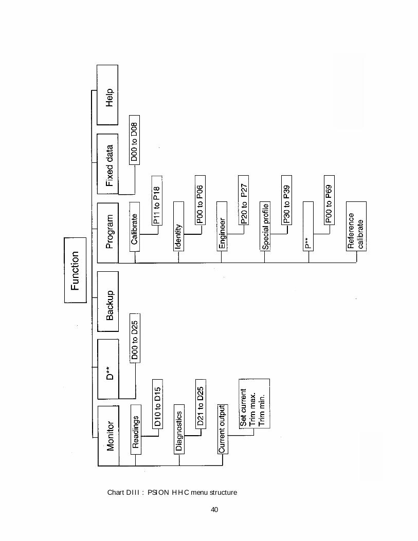
Chart DIII : PSION HHC menu structure

39 IP2020Nov 00
Microprocessor Parameters
D8.0 Introduction and FUNCTION menu
The microprocessor in the transmitter retains the calibration required for the particular applicationor tank involved, once this has been entered into the memory (EEPROM). On the initial interrogation of thetransmitter, this information is transferred to the SMART Communicator using the HART protocol, whichdefines the command structure and message format.
When received by the SMART Communicator, these messages are loaded into the WORKING register(which resides in the Psion Organiser memory), which then adds the descriptions and other informationshown on the 4 line liquid crystal display. The operator is presented with the information he requested, in ameaningful format in relation to the application.
The first selections of the transmitter programme use a menu structure, where the operatoridentifies the part of the programme required from a list of options available. The detailed informationunder each menu item can be inspected, after selection, by scrolling through the listing. Each item is given anidentifier in the top right hand corner of the screen, identified by a parameter reference number, to allowaccurate recording of the data interrogated and to simplify communications relating to this data.
The programme is divided into two main sets of data, selected from the FUNCTION menu. TheFUNCTION menu is the first programme screen presented when the data from the transmitter is acceptedand interrogation is to begin.
***** FUNCTION *****Monitor ProgramBackup Fixed dataD** Help
The structure of the programme built around this display screen is shown in Chart DIII.
MONITOR – The data presented on selecting MONITOR is the live “read only” information from thetransmitter, for example the liquid level in the tank, and the value of the current output. These parametersare labelled D, for Display information parameters, and are indexed between D10 and D25. The Displayparameters are described and listed in Section D10.0
PROGRAM – The data presented on selecting PROGRAM is the operator adjustable data used to configurethe transmitter for the particular application. These are “read/write” parameters, labelled P for Programparameter, and are indexed from P00 to P69. The Program parameters are described and listed in SectionD10.0
FIXED DATA – These are the factory preset display parameters, identifying the equipment type,serial number, software information, etc.
BACK UP – This menu item controls the transfer of data between registers or a file available in the PsionOrganiser memory: operation is described in Section D13.0.
D** - Allows direct access to a Display parameter by entering the relevant code number.
HELP – The HELP information display screens give some introductory advice on the use of the keys on thePsion Organiser and the Programme structure.
D8.1 Monitor/Display Parameters – D**
Access and programme structureThe Display Parameters (D**) are separated into three blocks giving three types of operator read onlyinformation. These are shown in Fig. DIII.
40 IP2020Nov 00
Chart DIII : PSION HHC menu structure
41 IP2020Nov 00
FIXED DATA – is accessed from the FUNCTION menu, and defines factory set identification codes.These are D00 to D08.
READINGS – are the actual level measurement values live from the transmitter, and are the processmeasurements of interest to the operator. These are D10-D15, and are accessed from the MONITOR menu.
DIAGNOSTICS – are the live values and data of interest to the transducer maintenance engineer, to assessthe performance of the transmitter. These are D20-D25, accessed from the MONITOR menu.
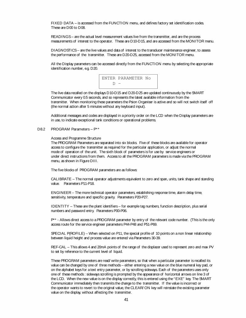
All the Display parameters can be accessed directly from the FUNCTION menu by selecting the appropriateidentification number, e.g. D20.
ENTER PARAMETER No D -
The live data recalled on the displays D10-D15 and D20-D25 are updated continuously by the SMARTCommunicator every 0.5 seconds, and so represents the latest available information from thetransmitter. When monitoring these parameters the Psion Organiser is active and so will not switch itself off(the normal action after 5 minutes without any keyboard input).
Additional messages and codes are displayed in a priority order on the LCD when the Display parameters arein use, to indicate exceptional tank conditions or operational problems.
D8.2 PROGRAM Parameters – P**
Access and Programme StructureThe PROGRAM Parameters are separated into six blocks. Five of these blocks are available for operatoraccess to configure the transmitter as required for the particular application, or adjust the normalmode of operation of the unit. The sixth block of parameters is for use by service engineers orunder direct instructions from them. Access to all the PROGRAM parameters is made via the PROGRAMmenu, as shown in Figure DIII.
The five blocks of PROGRAM parameters are as follows:
CALIBRATE – The normal operator adjustments equivalent to zero and span, units, tank shape and standingvalue. Parameters P11-P18.
ENGINEER – The more technical operator parameters, establishing response time, alarm delay time,sensitivity, temperature and specific gravity. Parameters P20-P27.
IDENTITY – These are the plant identifiers – for example tag numbers, function description, plus serialnumbers and password entry. Parameters P00-P06.
P** - Allows direct access to a PROGRAM parameter by entry of the relevant code number. (This is the onlyaccess route for the service engineer parameters P44-P48 and P51-P69.
SPECIAL P(ROFILE) – When selected on P11, the special profile of 10 points on a non linear relationshipbetween liquid height and process value are entered via Parameters 30-39.
REF-CAL – This allows 4 and 20mA points of the range of the displacer used to represent zero and max PVto set by reference to the current level of liquid.
These PROGRAM parameters are read/write parameters, so that when a particular parameter is recalled itsvalue can be changed by one of three methods – either entering a new value on the blue numeral key pad, oron the alphabet keys for a text entry parameter, or by scrolling sideways. Each of the parameters uses onlyone of these methods : sideways scrolling is prompted by the appearance of horizontal arrows on line 3 ofthe LCD. When the new value is on the display correctly, this is entered using the “EXE” key. The SMARTCommunicator immediately then transmits the change to the transmitter. If the value is incorrect orthe operator wants to revert to the original value, the CLEAR/ON key will reinstate the existing parametervalue on the display, without affecting the transmitter.
42 IP2020Nov 00
Within the memory of the Psion Organiser there are four separate registers for each of the PROGRAMParameters. These registers are known as WORKING, SAFE, OFFLINE and DEFAULT, and are furtherdescribed in Section D13.0. All programme changes are made in the WORKING register, and these are thevalues sent to the Transmitter memory. The display can be cycled through the registers by using theMODE key, and the initial letter of the register currently displayed is shown at the right hand end of thesecond line – the same line as the parameter value. Individual parameters can be moved into the WORKINGregister from other registers, by pressing the EXE key whilst the required register value is displayed.
WORKING REGISTER
Holds the same value as is currently in the transmitter.
SAFE REGISTER
Use as a backup, can only be sent to the same transmitter as it was loaded from.
OFF-LINE REGISTER
General purpose register, use to program a transmitter offline or transfer data between transmitters of thesame type.
DEFAULT REGISTER
The normal ex-factory values.
When a new value is programmed into certain parameters a warning message OUTPUT MAY BECHANGED is displayed with the option to proceed with or abort this change. This may be of importancewhere the output, either digital or analogue, is controlling some process, such that a sudden change couldcause problems.
D9.0 Keyboard Functions
ON/CLEAR KEY
Aborts data entry if this has been started, else returns to the previous menu.
EXE KEY
When display is read/write parameter, writes the value on line 2 or the list selection on line 3 to thetransmitter.
- AND ¯ ARROW KEYS
Used to step through a parameter block in numerical order.
MODE KEY
Used to access the WORKING, SAFE and OFF-LINE registers and the DEFAULT value while a read/writeparameter is being displayed. The selected register is indicated by W, S, O or D on the right hand side of line2.
¬ AND ® ARROW KEYS
Used to select an item from a list when <> is displayed on the right of line 3.
P** AND D** ENTRY
Allows direct access to a parameter via its number. Other parameters in the same group can then be accessedby the - and ¯ arrow keys.

43 IP2020Nov 00
D10.0 Parameter List
The performance of the DT Series is controlled by parameters stored in its non-volatile memory. Some of theseparameters are set at the factory and some are set by the customer. Further parameters are produced by the DT Seriesto provide information about its performance. The parameters used to set up the transmitter are called Program or“P” parameters. The parameters produced by the transmitter to provide information to the user are called Diagnosticor “D” parameters. All parameters used in the DT Series are listed below. All of these parameters are accessible usinga Handheld Communicator. Only parameters P15, P16 and P20 may be changed using the MSP-MMS magneticscroller. Further details are provided in Section D11.0
PROGRAM PARAMETERS
IDENTITY GROUP
P00 MESSAGE general purpose 32 character messageP01 TAG transmitter identifier (8 characters)P02 DESCRIPTION of, say, transmitter application or location (16 char)P03 DATE when last change made to sensorP04 FINAL ASSY No hardware assembly numberP05 SENSOR SERIAL No LVDT serial numberP06 PASSWORD 3 level password system
CALIBRATE GROUP
P11 CURVE PROFILE curve shape optionP12 PV DISPLAY UNITS select units associated with the PVP13 PV SCALE FACTOR PV max valueP14 STANDING VALUE value of PV at zero levelP15 CALIBRATION MAX PV for 20mA outputP16 CALIBRATION MIN PV for 4mA outputP17 LEVEL FOR MAX PV height up displacer at which PV is maximumP18 LEVEL FOR MIN PV height up displacer at which PV is minimum
ENGINEERING GROUP
P20 SMOOTHING TIME time constant applied to outputP21 ALARM DELAY time before alarm action P22 is takenP22 ALARM ACTION current out on alarm condition detectionP23 DISPLAY 1 parameter to be displayed on display moduleP24 DISPLAY 2 optional second parameter to be displayedP25 PROCESS TEMP used to compensate system for process tempP26 SG LOWER specific gravity of the lower liquidP27 SG UPPER specific gravity of the upper liquid
CURVE PROFILE GROUP
P30 10% HT %PV at 10% liquid heightP31 20% HT %PV at 20% liquid heightP32 30% HT %PV at 30% liquid heightP33 40% HT %PV at 40% liquid heightP34 50% HT %PV at 50% liquid heightP35 60% HT %PV at 60% liquid heightP36 70% HT %PV at 70% liquid heightP37 80% HT %PV at 80% liquid heightP38 90% HT %PV at 90% liquid heightP39 100% HT %PV at 100% liquid height
PROTECTED GROUP
P44 ELEC TEMPERATURE for sensor assembly correctionP45 TEMP COEFFICIENT for temperature correction of sensor assemblyP46 TEMPERATURE MAX the highest sensor temperature readingP47 TEMPERATURE MIN the lowest sensor temperature readingP48 BYTE READ/WRITE diagnostic tool for service engineer only
P51 DISPLACER LENGTH length of displacer elementP52 DISPLACER CS AREA cross-sectional area of displacerP53 DISPLACER WEIGHT weight of suspended parts

44 IP2020Nov 00
P54 SPRING MATERIAL spring material selectable from menuP55 SPRING RATE linear extension rate of spring
P58 TEMP SETUP process temperature assumed at factory setupP59 SG SETUP SG of upper fluid assumed at factory setup
P60 MIN SENSOR OUTPUT base value of D21P61 LVDT COEFF 1 first order coefficient for polynomial correctionP62 LVDT COEFF 2 second order coefficient for polynomial correctionP63 LVDT COEFF 3 third order coefficient for polynomial correctionP64 LVDT COEFF 4 fourth order coefficient for polynomial correctionP65 LVDT COEFF 5 fifth order coefficient for polynomial correctionP66 LVDT GAIN FACTOR to normalise LVDT outputP67 LVDT RATE rate of change of LVDT outputP68 UPPER SENSOR LIMIT maximum usable value of sensor output D21P69 LOWER SENSOR LIMIT minimum usable value of sensor output D21
DIAGNOSTIC PARAMETERS
FIXED DATA GROUP
D00 MANUFACTURER ID MOBREYD01 TRANSMITTER TYPE MLT100 order codeD02 PREAMBLE BYTES no. of bytes to set up modulationD03 UNIV COMMAND REV protocol revision conformed toD04 TS COMMAND REV MOBREY command specificationD05 SOFTWARE REV instrument software version numberD06 HARDWARE REV instrument hardware version numberD07 FLAGS see HART protocol specificationD08 DEVICE ID NUMBER factory-set unique address of sensor
READINGS GROUP
D10 PROCESS VALUE output calculated from the levelD11 LEVEL immersed length of displacerD12 CURRENT OUTPUT proportional to PV - limits set on P15 and P16D13 PERCENT OUTPUT current output as % of full scaleD14 ULLAGE space available (refill quantity)D15 ALARM REPORT active alarms/warnings - press ® for next alarm
DIAGNOSTICS GROUP
D21 NORMALISED sensor output after linearisation & smoothingD22 COMPENSATED sensor output after temp compensationD23 RAW LVDT OUTPUT unprocessed sensor outputD24 PERCENT OF RANGE % of range of level of interest between P17 & P18D25 TEMPERATURE sensor temperature monitored or preset using P44

45 IP2020Nov 00
D11.0 Parameter Descriptions
The DT Series stores a wide range of parameters, enabling it to perform more functions than a simple 4 to 20mAtransmitter. Some of these parameters are required to comply with the HART protocol whilst others, for example,enable the transmitter to calculate and display the contents of a non-linear vessel in true volumetric units.
The DT Series “Program” parameters each have default values which are loaded into the transmitter’s memory whenfirst manufactured. Some of these values are adjusted at the factory to suit the customer’s application. Several of theparameters have upper and lower limits outside of which they should not be set. These limits are defined within thetransmitter itself and, in the case of Handheld Communicators supplied are also set in the Communicator.Certain parameters, when changed, can cause a step change in the output. In these cases the HHC will prompt forconfirmation before making the change. This gives the user the opportunity to, say, put the control loop into manual.
This section of the manual details the function of each parameter in numerical order, together with its default valueand limits if applicable. A typical screen from the HHC is shown for each parameter.
P00 MESSAGEThe MESSAGE is a 32 character alphanumeric text string which may be stored in the transmitter so that the user may,for example, record details of the application.The default value is: DISPLACER LEVEL TRANSMITTER
MESSAGE P00******************** GENERAL PURPOSE 32 CHARACTER MESSAGE
P01 TAGThe TAG is an 8-character identifier. It is displayed whenever the HHC establishes communication with a HARTtransmitter.The default value is: MLT
TAG P01 ******** TRANSMITTERIDENTIFIER (8 CHAR)
P02 DESCRIPTIONThe DESCRIPTION is a 16-character field which may, say, be used to provide further detail on the application.The default value is: MLT TRANSMITTER
DESCRIPTION P02 **************TRANSMITTER USE ORLOCATION (16 CHAR)
P03 DATEThe DATE may be used to store the date when the last changes are made to the transmitter’s configuration. TheCK1 HHC automatically loads the correct date if it makes any such changes.The default value is typically: 01/01/97
DATE WAS P03** *** **** WHEN LAST CHANGE MADE TO SENSOR

46 IP2020Nov 00
P04 FINAL ASSY NoThe Final Assembly Number is a Unique Number allocated to the transmitter at the factory.
FINAL ASSY No PO4 ******** HARDWARE ASSEMBLY NUMBER
P05 SENSOR SERIAL NoThe Sensor Serial Number is the serial number of the LVDT which provides the level input signal to the electronics.
SENSOR SERIAL No PO5 ******** INSTRUMENT SERIAL NUMBER
P06 PASSWORDThe Password controls changes to the parameters within the transmitter. It has 3 possible values:CLOSED – this prevents any changes to parameter settingsOPEN – this allows configuration of the transmitter to suit the applicationOPENx this additionally allows access to the “protected” parameters which relate to the calibration of thetransmitter. These should not be adjusted without reference to the factory.The default value is: OPEN
PASSWORD P06 *****
P11 CURVE PROFILEThe DT Series can provide an output proportional to volume, flow or contents in a non-linear application. The DTsystem is pre-programmed with a selection of common non-linear profiles detailed in the Non-linear Profiling sectionof this manual. These profiles may be selected using the ¬ and ® keys. Selecting “Special” allows the user to plothis own curve.The default value is: Linear
CURVE PROFILE P11 ****** ****** CURVE SHAPE OPTION
Refer to Appendix E for further details of this facility.
P12 PV DISPLAY UNITSThe Process Value (PV) may be configured to display a wide range of variables from Levels to Volumes. P12 enablesthe user to associate appropriate units to the calculated value, and these units will be displayed on the optional integraldisplay and on the HHC.The default value is: metres
PV DISPLAY UNITS P12 ****** ****** RESET MATHS ON P13
ß àß àß àß àß à
ß àß àß àß àß à

47 IP2020Nov 00
P13 PV SCALE FACTORThe PV Scale Factor enables the transmitter to provide an answer in the customer’s preferred units. Typically it maybe used to give an answer of volume in cubic metres. The value of P13 should be set to the maximum (100%) valueof the PV. If the value is set to Automatic then the transmitter takes the displacer length (or the span defined by P17and P18) as its full-scale range and adjusts the output accordingly. See also the appendix on the Block Diagram.The default value is: Automatic
PV SCALE FACTOR P13 ********* MAX VALUEAUTOMATIC (A) = P51
P14 STANDING VALUEA displacer level transmitter can only give a meaningful output over the length of its displacer. If, however, the vesselstill has some contents when the level is at the bottom of the displacer then this value may be added to the PV byentering the difference value in P14. P14 may be positive or negative.The default value is: 0.0
STANDING VALUE P14 **** ** VALUE OF PV AT ZERO LEVEL
P15 CALIBRATION MAXAfter calculating the PV, the transmitter will normally output a 4-20mA signal proportional to the value. P15 may beused to set the value of PV which is used to represent 20mA. A value of Automatic will use the displacer length tospecify the height at which to output 20mA. This parameter and P16 may also be adjusted via the Caliplug – seesection on Commissioning.The default value is: AutomaticCan also be set by using the ref cal option on the program menu.
CALIBRATION MAX P15 ******* ** PV FOR 20mA OUTPUTAUTOMATIC (A) = P51
P16 CALIBRATION MINAfter calculating the PV, the transmitter will normally output a 4-20mA signal proportional to the value. P16 may beused to set the value of PV which is used to represent 4mA. This parameter and P15 may also be adjusted via theCaliplug – see section on Commissioning.The default value is: 0.0Can also be set by using the ref cal option on the program menu.
CALIBRATION MIN P16 ******* ** PV FOR 4mA OUTPUT
P17 LEVEL FOR MAX PVThe top end of the displacer is not necessarily the level which is required to represent the maximum PV. P17 can beused to specify another level for this purpose and subsequent calculations will be based upon this revised point. Seealso the appendix on the Block diagram.The default value is: Automatic, meaning the max. PV is at the top of the displacer.Can also be set by using the ref cal option on the program menu.

48 IP2020Nov 00
LEVEL FOR MAX PV P17 ****** m HEIGHT UP DISPLACERAUTOMATIC (A) = P51
P18 LEVEL FOR MIN PVThe bottom end of the displacer is not necessarily the level which is required to represent zero PV. P18 can be usedto specify another level for this purpose and subsequent calculations will be based upon this revised point.The default value is: 0.0Can also be set by using the ref cal option on the program menu.
LEVEL FOR MIN PV P18 ****** mHEIGHT UP DISPLACER
20 SMOOTHING TIMEIn circumstances where the level is unstable it may be beneficial to adjust the amount of damping applied to the PVand current output. P20 may be set to any value between 0 and 100 seconds. This parameter may also be adjusted viathe Caliplug – see section on Commissioning.The default value is: 5 seconds
SOOTHING TIME P20 ** s TIME CONSTANT USED ON OUTPUT DATA
P21 ALARM DELAYThe transmitter continuously monitors its performance and will signal an alarm if certain parameters go outside ofpre-determined limits. Under these circumstances it will signal that an alarm condition exists as described under P22below. P21 may be used to set the delay between the alarm condition occurring and the transmitter signalling.The default value is: 5 seconds
ALARM DELAY P21 ** s DELAY BEFORE ALARMACTION(P22) IS TAKEN
P22 ALARM ACTIONThe transmitter continuously monitors its performance and will signal an alarm if certain parameters go outside ofpre-determined limits. See appendix on Error Messages for possible alarm conditions. An alarm condition issignalled by:Setting an Alarm bit in every HART messageFlashing an Alarm message on the display (if fitted)Setting its current output to a user-defined state set by P22.The options for P22 are to set the current to 3.6mA, 21mA or to Hold the last reading.The default value is: Hold
ALARM ACTION P22 **** ****CURRENT OUT ON FAULT
ß àß àß àß àß à

49 IP2020Nov 00
P23 DISPLAY 1The display module, if fitted, can be programmed to display any 1 or 2 parameters from a selection of parameters.P23 is used to define Display 1. The ¬ and ® keys may be used to make the selection. The choice is from:PVLevelCurrent (Output)Percent (Current Output)UllageSensor Outputs D21à D23Percent of PV Range D24Temperature D25The default value is: PV
DISPLAY 1 SELECT P23 *** *** IF FITTED
P24 DISPLAY 2In a similar way to P23, P24 can be used to define a second display which will flash alternately with Display 1 on thedisplay module. It has the same choice as for P23 except for the addition of “none” if no second display is required.When flashing, the 2 displays are distinguished by the Display 1 and Display 2 being accompanied by arrows - and ¯respectively.The default value is: none
DISPLAY 2 SELECT P24 *** ***IF FITTED - OPTIONAL
P25 PROCESS TEMPThe process temperature has an effect on the performance of the transmitter. This effect will have been allowed forin the factory calibration. If, however, the temperature is significantly different from that originally specified, it maybe compensated for by entering a revised value in P25. If set to Automatic then the value from the temperaturesensor in the enclosure is used.The default value is: Automatic
PROCESS TEMP P25 ***** °CUSED TO COMPENSATE FOR PROCESS TEMP
P26 SG LOWERThe performance of a Displacer Level Transmitter is dependent on the specific gravities of the Lower and Upperfluids. The transmitter will have been calibrated for certain SGs in the factory but, subject to certain limitations,revised values may be entered in P26 and P27 to match the true process conditions.The default value is: 1.0
SG LOWER P26 **** SPECIFIC GRAVITY OF LOWER LIQUID
ß àß àß àß àß à
ß àß àß àß àß à

50 IP2020Nov 00
P27 SG UPPERSee also P26 above. At the factory, the transmitter will have been calibrated for certain process conditions. The SGof the upper fluid is stored in P27 and P59. The value in P59 should not be changed but P27 may be adjusted tomatch revised process conditions.The default value is: 0.0
SG UPPER P27 **** SPECIFIC GRAVITY OF UPPER LIQUID
P30 to P39 NON-LINEAR PROFILE POINTSWhen a non-linear profile has been selected by P11, the profile is plotted using parameters P30 to P39. Each plotpoint represents the percentage of maximum PV corresponding to 10% increments in level. The range of this levelis defined by P17 and P18 relative to the bottom end of the displacer. For further details see Non-linear Profiling inD12.0The default values provide a linear output.
PROFILE POINT 1 P30%LEVEL FOR PV(%P13)10% LEVEL @ 10.0%ß20% LEVEL @ 20.0%
IMPORTANT NOTE :Parameters P44 to P69 are vital to the calibration of the transmitter and should not be adjusted withoutauthority from qualified personnel, for which password access will be required.
P44 ELEC TEMPERATUREThe level sensor and its associated electronics have a small temperature co-efficient and so to optimise accuracy atemperature sensor provides automatic compensation. However, the measured value can be overridden using P44.The default value is: Automatic
ELEC TEMPERATURE P44 ** °CFOR SENSOR ASSEMBLYCORRECTION - A=AUTO
P45 TEMP COEFFICIENTThe temperature co-efficient of the level sensor and its associated electronics is stored in P45 and provides automatictemperature compensation.The default value is optimised for the transmitter.
TEMP COEFFICIENT P45 ***FOR TEMP CORRECTION OF SENSOR ASSEMBLY
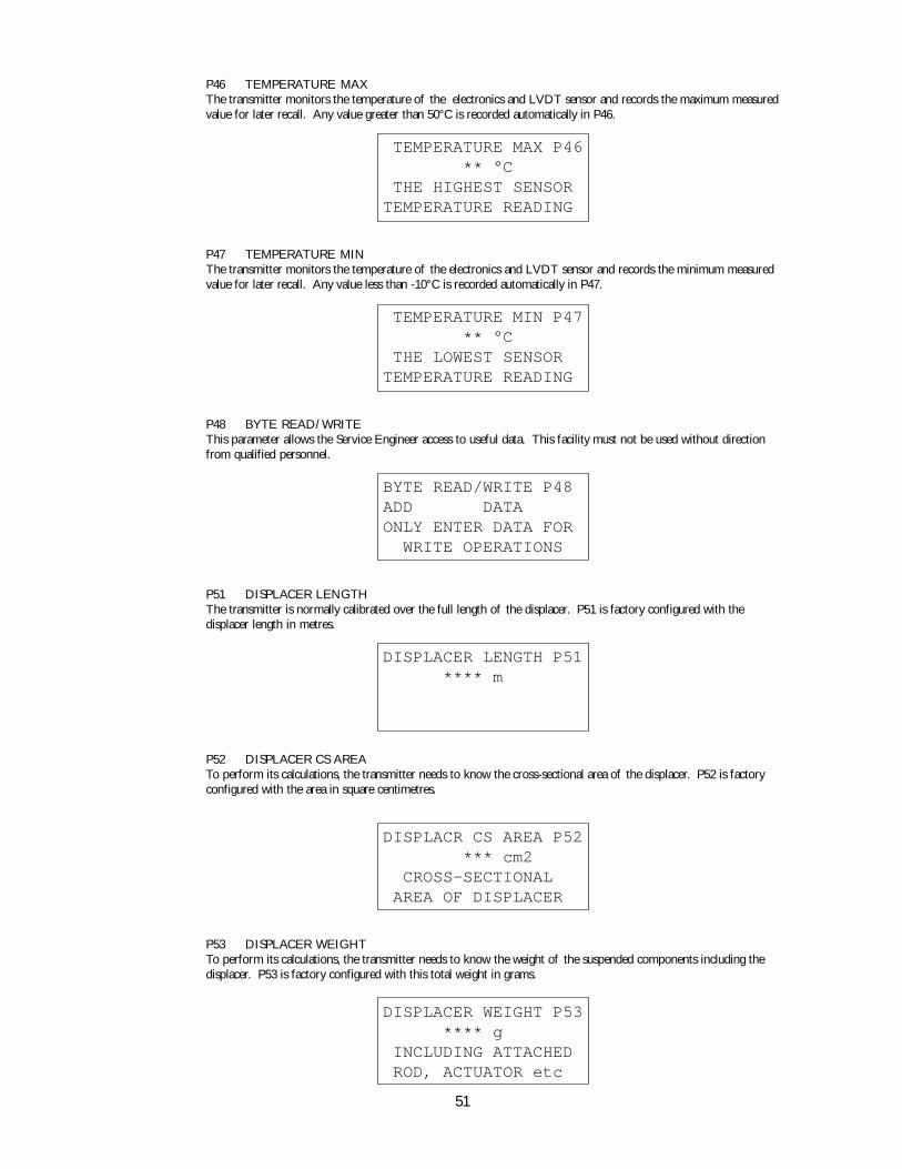
51 IP2020Nov 00
P46 TEMPERATURE MAXThe transmitter monitors the temperature of the electronics and LVDT sensor and records the maximum measuredvalue for later recall. Any value greater than 50°C is recorded automatically in P46.
TEMPERATURE MAX P46 ** °C THE HIGHEST SENSORTEMPERATURE READING
P47 TEMPERATURE MINThe transmitter monitors the temperature of the electronics and LVDT sensor and records the minimum measuredvalue for later recall. Any value less than -10°C is recorded automatically in P47.
TEMPERATURE MIN P47 ** °C THE LOWEST SENSORTEMPERATURE READING
P48 BYTE READ/WRITEThis parameter allows the Service Engineer access to useful data. This facility must not be used without directionfrom qualified personnel.
BYTE READ/WRITE P48ADD DATAONLY ENTER DATA FOR WRITE OPERATIONS
P51 DISPLACER LENGTHThe transmitter is normally calibrated over the full length of the displacer. P51 is factory configured with thedisplacer length in metres.
DISPLACER LENGTH P51 **** m
P52 DISPLACER CS AREATo perform its calculations, the transmitter needs to know the cross-sectional area of the displacer. P52 is factoryconfigured with the area in square centimetres.
DISPLACR CS AREA P52 *** cm2 CROSS-SECTIONAL AREA OF DISPLACER
P53 DISPLACER WEIGHTTo perform its calculations, the transmitter needs to know the weight of the suspended components including thedisplacer. P53 is factory configured with this total weight in grams.
DISPLACER WEIGHT P53 **** g INCLUDING ATTACHED ROD, ACTUATOR etc

52 IP2020Nov 00
P54 SPRING MATERIALTo perform its calculations, the transmitter needs to know the characteristics of the spring material. P54 specifies thespring material from which the transmitter can calculate the relevant characteristics.
SPRING MATERIAL P54 *** ***
P55 SPRING RATETo perform its calculations, the transmitter needs to know the rate of the spring. P55 is factory configured with theactual spring rate in gram per centimetre.
SPRING RATE P55 *** g/cm LINEAR EXTENSION RATE OF SPRING
P58 TEMP SETUPTo optimise the design of the transmitter, it is necessary to know the process temperature in which the transmitterwill be operating. This is stored in P58. If the actual process temperature is significantly different from that advisedat the time of order, then the revised value should be entered in P25 – no change should be made to P58.
TEMP SETUP P58 *** °CPROCESS TEMPERATURE ASSUMED AT SETUP
P59 SG SETUPTo optimise the design of the transmitter, it is necessary to know the specific gravity of the upper fluid in which thetransmitter will be operating. This is stored in P59. If the actual upper SG is different from that advised at the timeof order, then the revised value should be entered in P27 – no change should be made to P59.
SG SETUP P59 *** SG OF UPPER FLUID ASSUMED AT SETUP
P60 MINIMUM SENSOR OUTPUTDuring factory calibration, the value of the LVDT level sensor output at zero level is recorded and stored as P60.This is the reference value upon which the transmitter bases its calculations.
MIN SNSR OUTPUT P60 **** mV BASE VALUE OF D21
P61 to 65 LVDT COEFFICIENTS 1 to 5To provide a linear output over the operating range, the LVDT sensor output is linearised by a fifth order polynomial.These polynomial co-efficients are stored as P61 to P65.
LVDT COEFF 1 P61 ****VALUE FOR POLYNOMIAL CORRECTION
ß àß àß àß àß à

53 IP2020Nov 00
P66 LVDT GAIN FACTORIn order to allow interchangeability of the LVDT sensor, the output is normalised to achieve a common span. Thegain factor is stored as P66
LVDT GAIN FACTOR P66 **** TO NORMALISE LVDT OUTPUT
P67 LVDT RATEAfter processing the LVDT output the overall sensor system produces an electronic output proportional to linearmovement. P67 defines the sensitivity of the sensor in milli-volts per cm.
LVDT RATE P67 *** mV/cm RATE OF CHANGE OF LVDT OUTPUT
P68 UPPER SENSOR LIMITThe LVDT sensor is calibrated over a range where linear operation is guaranteed. In exceptional circumstances itsoutput may extend beyond the calibrated range and under these circumstances the transmitter will provide a warning.P68 stores the limit of the calibrated region at the upper end of the LVDT travel.
UPPER SNSR LIMIT P68 ***MAXIMUM USABLE VALUEOF SENSOR OUTPUT D21
P69 LOWER SENSOR LIMITSee also P68 above. P69 stores the limit of the calibrated region of LVDT movement at the lower end of the LVDTtravel.
LOWER SNSR LIMIT P69 ***MINIMUM USABLE VALUEOF SENSOR OUTPUT D21
The following “D” parameters are diagnostics read-only parameters which are either fixed in the transmitter atmanufacture (D00 to D08) or produced within the transmitter as a result of measurements taken (D10 to D25).
D00 MANUFACTURER IDFor HART communications to operate correctly, the transmitter must identify its manufacturer. The manufacturer’scode number automatically forms part of the communications address. The code is 59
MANUFACTURER ID D00 59

54 IP2020Nov 00
D01 TRANSMITTER TYPED01 stores the type code for the transmitter head.
TRANSMITTER TYPE D01
DISPLACER LEVELTRANSMITTER
D02 PREAMBLE BYTESD02 tells a HART master device how many preamble bytes it should send in its messages to the transmitter in orderto guarantee reliable communications. Sending too many bytes would simply slow down the communications updaterate. In the DT Series the value is fixed at 5.
PREAMBLE BYTES D02 5 NO OF BYTES TO SET UP MODULATION
D03 UNIV COMMAND REVD03 identifies the major revision of the HART protocol with which the transmitter complies. In the case of theDT Series it is revision 5.
UNIV COMMAND REV D03 5 PROTOCOL REVISION CONFORMED TO
D04 TS COMMAND REVOver a lifetime of a product type, extra functionality may be introduced by adding extra variables or commands. Tosignal this to a HART master device, D04 contains details of the Transmitter Specific Command revision
TS COMMAND REV D04 ** COMMAND SPECIFICATION
D05 SOFTWARE REVExtra software functionality, which does not affect HART, may be identified to the user by D05, the SoftwareRevision.
SOFTWARE REV D05 **INSTRUMENT SOFTWARE VERSION NUMBER
D06 HARDWARE REVThe presence of any hardware changes may be identified to the user by D06, the Hardware Revision.
HARDWARE REV D06 **INSTRUMENT HARDWARE VERSION NUMBER

55 IP2020Nov 00
D07 FLAGSThe Flags byte, D07, gives a HART master details of the transmitter’s HART functionality.
FLAGS D07 ** SEE HART PROTOCOL SPECIFICATION
D08 DEVICE ID NUMBERThe Device ID Number is a unique number which forms part of the transmitter’s HART address and ensures that notwo HART transmitters ever have the same address.
DEVICE ID NUMBER D08
FACTORY-SET UNIQUE ADDRESS OF SENSOR
D10 PROCESS VALUEThe DT Series is fundamentally a level measuring device and by default the Process Value or PV will be the level ofthe lower liquid. However, as described elsewhere in this manual, the level value can be processed to provide ananswer in terms of volume, mass or even flow. This resultant PV is displayed with its units as parameter D10.
PROCESS VALUE D10 ***** ** OUTPUT CALCULATED FROM THE LEVEL
D11 LEVELThe length of the displacer element that is immersed in the lower liquid is displayed as D11. The PV is calculatedfrom this basic level measurement
LEVEL D11 ***** m IMMERSED LENGTH OF DISPLACER
D12 CURRENT OUTPUTThe current output is related to the PV by parameters P15 and P16. Its value, in mA, is displayed as D12.
CURRENT OUTPUT D12 ***** mAPROPORTIONAL TO PVLIMITS SET P15+P16
D13 PERCENT OUTPUTA convenient alternative way of viewing the answer is as a percentage. D13 displays the PV as a percentage based onthe limits set on P15 and P16. If the current output is active, that is not in multi-drop mode, then this also representsthe percentage of current output – e.g. if the current is 12mA then D13 is 50%.
PERCENT OUTPUT D13 ***** %CURRENT OUTPUT AS % OF FULL SCALE

56 IP2020Nov 00
D14 ULLAGEThe Ullage space is the difference in the present PV and the maximum value defined by P15. In other words it is theamount in PV units required to fill the vessel so as to give 20mA current output.
ULLAGE D14 ***** ** SPACE AVAILABLE (REFILL QUANTITY)
D15 ALARM REPORTThe DT Series monitors its performance and detects if there is any malfunction or if any values go out of normallimits. The parameters it monitors are listed in Appendix D14.0. The HHC displays a full text message when thecondition is first detected and then truncates it to a 2 character code at the right hand end of the display. Only onecondition, the highest priority one, can be displayed at a time. However, D15 can be inspected to scroll through fulldescriptions of all active alarms.
ALARM REPORT D15 ******************* PRESS à FOR NEXT ALARM
D21 NORMALISED LVDT OUTPUTThe Level Sensor in the DT Series is a Linear Variable Differential Transformer (LVDT). The LVDT output goesthrough several stages of processing as shown in the Block Diagram in Appendix E. D21 is the LVDT sensor outputvalue after temperature compensation, linearisation, scaling, and smoothing.
NORMALISED D21 **** mVSENSOR OUTPUT AFTERPOLYNOMIAL+SMOOTHING
D22 COMPENSATED LVDT OUTPUTD22 is the LVDT sensor output value after temperature compensation.
COMPENSATED D22 ****SENSOR OUTPUT AFTER TEMP COMPENSATION
D23 RAW LVDT OUTPUTD23 is the LVDT sensor output value before any processing.
RAW LVDT OUTPUT D23 ****

57 IP2020Nov 00
D24 PERCENT OF RANGEThe DT Series produces a value (D11) for the liquid level relative to the bottom of the displacer element. However,this may not be the range of interest and P17 and P18 re-define where the minimum and maximum levels should be.D24 represents the position of the liquid level between these 2 limits.
PERCENT OF RANGE D24 **** %
D25 TEMPERATUREThe DT Series measures the temperature in the enclosure so that it may make corrections for changes in temperatureif necessary. D25 displays this measured value unless it is overridden by fixing the temperature with P44.
TEMPERATURE D25 *** °C MONITORED OR PRESET USING P44
REFERENCE CALIBRATE
The Ref_cal section allows the actual level of the liquid being measured to be used to set the current output and PVrange parameters.
The sensor output option allows P17 and P18 to be set. The current output option allows P15 and P16 to be set.
In both cases the present value of the parameter to be changed is displayed, with a prompt to continue. If selectedthe potential new value for the selected parameter is displayed and continually updated, with an” INPUT STABLE”prompt, if “Y” is pressed then the displayed value is written to the selected parameter. If “N” is pressed the processreturns to the previous screen.
At any stage, in either reference calibrate procedure, if the CLEAR/ON key is pressed then a return to thePROGRAM menu is immediately made.
D12.0. Using the Tank profile facility
P11 Curve Profile
CURVE PROFILE P11LINEAR 1NON-LINEAR < - - >CURVE SHAPE OPTION
Default value LINEAR
This parameter establishes the relationship to be used between the liquid level (or height) and the process valuederived from that level. The process value then drives the current loop.
The allowed selections on Parameter 11 are scrolled using the left and right arrows. Allowed selections are LINEARand then seven non-linear functions – SPECIAL, CYLINDER, SPHERICAL, CONICAL 1, CONICAL 2, FLUMEand VNOTCH WEIR. These are as follows:
D12.1 LINEAR – The process value (transmitter 4-20mA output) is a linear multiplier of the liquid height abovethe zero reference, in metres.
For a tank with constant cross section, the volume of the contents can be shown as the process value by selectingLINEAR on P11, and entering the maximum volume on P13. The units of measurement – gallons, litres, etc. – arethen set on P12. See Fig DIV

58 IP2020Nov 00
Fig. D.IV - Linear vessel or sumpTank Contents Curve Profiles for Standard Tank Shapes
Unless factory calibrated to your specific instructions, the DT Series will give a 4-20mA output proportional to level over it’s full length,with 4mA representing a level of 0m at the end of the displacer element. You can re-range on site if necessary (See 4.2).
If the displacer element does not cover the full depth of the tank, there is provision to add a standing level to the calculations. Simplyenter the level, in metres, on P14, and the DT Series will give a proportional output over the length of the displacer. Note that theoutput will now never reach 4mA, as the displacer length is now only a part of the full output range. You will need to re-set P17, theProcess Value for a 20mA output, by increasing the value by the standing level.Example :Displacer length 1.50m. : P17 = 1.50 / P18 = 0m / P14 = 0mTo allow for a standing level of 0,5m : P17 = 2.0m / P18 = 0m / P14 = 0.5mResulting output signal : 8mA at 0.5m and below, 20mA at 2.0m.
To operate in units other than metres, the “PV Scale factor” P13 can be used. (See D11.0 )
Example : To operate in feet, set P13 to the maximum value of the PV. For a displacer length of 1.5m, where PV max is 1.5m, setP13 to (1.5 x 1.094 ) = 1.641.If you wish to re-range the transmitter, you can reset P17 and/or P18 so that the transmitter output is proportional to level over thisnew range. Note, P17 and P18 are ALWAYS entered in metres.To operate in litres, set P13 to the volume in litres equivalent to the length of the displacer element. For an element of length of1.5m in a vessel of dia 2m, set P13 to 1.5 x ( p2.02) x 1000 = 4712litres
If there is a standing level (or volume) to be taken into account, this is entered on P14 as previously described, but note that the unitsMUST BE entered in the same units as the readout. i.e. feet or litres in the above examples. Whatever units are chosen for the readout,the display and / or HHC can be configured to suit using P12.
4
P12 UnitsPV DISPLAY UNITS P12Metres WMetres < - - >RESET MATHS ON P13
Default value metres
The units used to display the Process Value are set on Parameter 12. These units are also used to set the milliampoutput span and zero points on P15 and P16. The allowed units are scrolled by using the horizontal arrows. If theunits required are not present, then the displays can show no units by selecting “none” – possibly the actual units inuse can be entered in P00 (Message).The bottom line on the display of P12 reminds the operator that if units of measurement are changed, then themaths values on the scaling parameters (e.g. P13) should be recalculated and amended.
P13 Scale FactorPV SCALE FACTOR P131.0000 WMAX VALUEAUTOMATIC (A) = P51
Default value 1.00The PV Scale Factor provides the mathematics used to relate the Process Value to the liquid height, which is initiallymeasured by the transmitter in metres above the reference level.
This function can also be used to display height of liquid in feet or millimetres or other linear units, by adjusting P12and P13 appropriately.
P14 Standing level
D atum (default=dia. m )
P18 Level for m in P.V. (0% )
P17 Level for m axP.V. (100% )

59 IP2020Nov 00
D12.2 “NON-LINEAR” – All the non-linear functions selected have a curve or profile to relate the processvalue/output measurement to the liquid height. The functions therefore relate liquid volume contents toheight in a non-linear tank, or liquid flow in an open channel to the height upstream of an obstruction suchas a weir or flume.
For all selections other than LINEAR it is necessary to select the correct, site related values for Parameters 12 and 13as shown on in the following diagrams. The various non-linear profiles available are as follows:
Technical Note : The transmitter accepts the non-linear profiles from the SMART Interface in the form ofa 10 point plot of percentage of maximum process value against percentage of maximum level, and then usesinterpolation to produce values for intermediate points. The Psion Organiser calculates the ten points to be loadedin the memory according to the curve profile selected on P11. The values of these ten points can be seenon Parameters 30-39 : direct access to change these parameters is only available when the SPECIAL profile is selectedon P11.
CYLINDRICAL – When the PV output required is to represent the volume contents in a horizontally mountedcylindrical tank, this curve is selected. The dimension of the equivalent ideal tank are entered as shown in Fig. D.IV,assuming the tank is horizontal and has effectively flat ends.
SPHERICAL – To provide the PV output as volume contents in a spherical tank, this curve is selected. Theequivalent ideal spherical tank dimensions are entered in the parameters 10-14 as shown in D.IV. If the actual tankmeasurement range is limited by transducer positioning or tank shape to part of a sphere, the ideal full spheredimensions must be used. The 4-20mA output can then be restricted to operation over a smaller volume span ifrequired.
CONICAL – For rectangular or cylindrical tanks with a conical bottom two patterns are provided to suit differenttank aspect ratios. These are CONICAL 1 AND conical 2, shown in D.IV.
CONICAL 1 is for tanks where the major part of the tank height is taken up with the cone. The profile creates animaginary tank where the linear section is the same height as the conical section, and P13 and P14 are entered for thisimaginary tank. This profile is applicable on all tanks where the maximum height to be measured is less than twicethe conical section height, H. Note that the zero reference distance and the conical height is measured from the apexof the cone – where it would be without considering discharge pipework, etc.
CONICAL 2 is used for tanks which have a much smaller proportion of the height as a cone. It is applicable fortanks where the maximum measurement is up to 5 times the conical section height above the apex of the cone. Forhigher tanks the non-linearity introduced by the conical section becomes insignificant, and a LINEAR profile shouldbe used.
D12.3 SPECIAL – If the curve profile labelled SPECIAL is chosen, access is allowed to parameters P30-P39 todraw the unique profile for this site, tank or flume, according to data available. The microprocessor in thetransmitter then interpolates between these ten points to give an accurate curve fit for the PV output.
The standard procedure for using the SPECIAL profile is shown in Fig D.V, with some examples. It is necessary tohave either tabulated or graphical data to relate the required process value to the liquid height, to derive the requiredprofile points.
Technical Notes: The origin (0,0) of the graph of PV versus height is used in the interpolation as the start point.
Profile Point 10 occurs at the height used as the maximum level, normally the top of the displacer unless re-positioned by P17. It is possible that the PV value corresponding to this height is less than 100% of Parameter 13.This means that for ease of calculations of percentages, P13 can be selected as any value above the maximumrequired to be monitored.

60 IP2020Nov 00
SPECIAL PROFILE Parameters P30-39
For a non-linear relationship between PV and Liquid Level, Parameters 30 to 39 set out the 10 point graph relatingthe two functions. When Parameter 11 is used to a select a pre programmed function – e.g. contents of a cylindricalhorizontally mounted tank – CYLINDRICAL) Parameters 30-39 are automatically allocated values recalled from thememory of the Psion Organiser SMART Datapak. These values cannot be changed by accessing Parameters 30-39 –they are effectively “Read Only” parameters. This is useful in that the curve used is defined and shown. (Beware thatif LINEAR is selected on P11 the Parameters P30-39 retain their previous values – the LINEAR profile ignores P30-39). Any attempt to write new values to these parameters will receive the screen response.
PROFILE POINTSPROTECTED BY P11
When Parameter 11 is set to the “SPECIAL” non-linear profile, access is allowed for the operator to write values intoP30-P39, as described in Figure 9, to construct a special profile relating PV to height. Both of these are expressed aspercentages of the maximum or “full” value in Parameters 30 to 39.
The profile points are scrolled on the same screen, to allow previous points to be monitored. For example, the displayshowing Point 4, Parameter 33, is as follows, where the arrow indicates the value which is to be adjusted:
PROFILE POINT 4 P3330% LEVEL @ 25.2%40% LEVEL @ 37.3% ¬50% LEVEL @ 50.0%
The initial screen shown for Parameter 30 reminds the operator that the Liquid Level is expressed as a percentage ofthe P14 value, and the PV corresponding to this level is expressed as a percentage of P13.
PROFILE POINT 1 P30¬ % LEVEL for PV(%P13)10% LEVEL @ 10.0% ¬20% LEVEL @ 20.0%
Default values LINEAR ProfileMaximum values 100%Minimum values 0%

61 IP2020Nov 00
Special profile relationship between process alue and liquid height
Example :
P36 is a Profile Point 7. Find X co-ordinate that represents 70% of the max height (P17-P18). On graph obtain Yco-ordinate and express as percentage of max value (P13). Enter this percentage as P36.
Fig. D. V.

62 IP2020Nov 00

63 IP2020Nov 00
HAND HELD COMMUNICATOR REGISTERS
D13.0 SAFE, WORKING, OFFLINE, DEFAULT, Registers
Introduction to RegistersFrom the FUNCTION screen, whilst interrogating an transmitter, there is a selection titled “BACKUP”.This allows the data now stored in the WORKING register (i.e. the transmitter data) to be transferred to aseparate secure memory, to either retain it while making changes to the transmitter (i.e. as a “revert to theoriginal program” insurance data store) or to save it in memory so that it can be copied or consulted back in theoffice. The registers available are shown in Fig DVI, and are listed as:
WORKING REGISTERThis is literally the work sheet where all work is done – all changes made to the parameters on the SMARTCommunicator keyboard are made to the data in the WORKING Register. While the Communicator is attachedacross the 4-20mA loop, the WORKING register is exactly the same as the transmitter memory, so allchanges made to the WORKING register are also made to the transmitter itself. The transmitter memoryand the WORKING register in the SMART Communicator are identical. If communication between the two unitsfails, then changes attempted in the WORKING register will be rejected.
Note : The SMART Communicator can be unaware of changes to the transmitter memory made by (a) aPrimary Master (such as H-View) also attached to this transmitter loop, and (b) the local zero and span on theDT Series.
The data existing in the WORKING register is overwritten (and therefore lost) when new data is loaded from anotherregister, or when the SMART communicator is reconnected to an DT Series loop, because the start up routine will loadthis new memory into the WORKING register. To save any data that has been entered in an “Off-loop”state (i.e. back in the office) the data must be held in the OFFLINE register (see below).
It is recommended that the data in the WORKING register is transferred OFFLINE before disconnection of theSMART communicator from the loop, if it is likely to be needed for reference back in the office. However, the datain the WORKING register is retained in the Psion memory after this disconnection, and can still be interrogated untiloverwritten by new data.
SAFE REGISTERThe SAFE Register is literally a register where the current calibration data can be stored and kept SAFE,while changes are made on the WORKING register and the SMART Communicator is attached to the loop. If theseWORKING register changes then prove ineffective or not required, the SAFE register data can be recalled into theWORKING register (and therefore to the transmitter) to reset all the parameters to their originalvalues – i.e. the values in the transmitter when the last “Backup” operation transferring the data to the SAFE registerwas carried out. The data in the SAFE register can only be loaded into the WORKING REGISTER when thecommunicator is attached to the same transmitter that was the source of the data – i.e. the transmitter withthe same unique identifier (D08). It is not possible to transfer programmes between instruments using the SAFEregister.
The SAFE register is retained even when the Communicator is disconnected from the loop, powered down, and thenreconnected to another loop, collecting new data in the WORKING register. It is not accessible until the correcttransmitter loop is interrogated, so that the check on the D08 Unique Identifier has been satisfied.
OFF-LINE REGISTERThis is the register used for transfer of programmes between one unit and the next, or from a programme developedon the SMART Communicator at the office desk, stored OFF-LINE and then down loaded into antransmitter on the plant later. Such data transfer is achieved by connecting the SMART Communicator across therelevant loop, loading the WORKING register with the current program (see below) thentransferring the OFF-LINE stored data into the WORKING register – this overwrites the previous programme in(both the transmitter memory and the WORKING Register).
An obvious precaution in the above procedure after loading the WORKING register with the currenttransmitter data, is to transfer this data to the SAFE register in case the OFF-LINE sorted new programme does notgive the expected result – if necessary the DT Series can be restored to its original programme status by transferringthe SAFE register data to the WORKING register.
The OFF-LINE register is retained when the communicator is disconnected from the loop or powered down. It isonly wiped when a new set of data is transferred to the OFF-LINE register from the WORKING register.
Only one set of parameters can be stored in the OFF-LINE register at once.

64 IP2020Nov 00
MEMORY LOCATIONS IN SMART COMMUNICATOR
SAFEregister
WORKINGregister
MSP100transmittermemory
SAFE register keeps data from onspecific transmitter secure, and onlyallows transfer to/from thattransmitter
WORKING register. All changes aremade in this register. When on a loop,this shows the MSP100 transmittermemory.
OFFLINE is used to save data forwork or interrogation in the office,or transfer between MSP100transmitters.
The exfactory values can bereloaded into the WORKINGregister by recalling the DEFAULTRegister
OFFLINERegister
DEFAULTvalues
uuuuu
uuuuu
uuuuu
Fig. DVI :

65 IP2020Nov 00
DEFAULT REGISTERThis is the register of all the normal ex factory settings for the Transmitter. It is a useful start or referencepoint for programming any transmitter, since the values set in each parameter are known and only those that needreprogramming have to be amended. The DEFAULT values can also be used to reset any transmitter to exfactory status, therefore wiping any other programme amendments made previously.
D13.2 Manipulation and Transfers between registers
a) Offline operationThe screens showing the Transfer functions of data between registers provide step by step instruction for achievingsuch data transfer (See Figure D.VIi). There are also facilities for allowing the normal interface between the PsionOrganiser and a printer or personal computer to provide output of the programme data.
The options presented on the LCD are amended when the SMART Communicator senses that a loop is not presentor the Interface unit is not plugged into the Psion. In such cases OFF-LINE operation is offered or selectedautomatically (See Figure D.VII). After changes to the PROGRAM screens which modify data in the WORKINGRegister, these changes must be saved in the OFF-LINE Register or to a Data File using the TRANSFER function.
b) Loop transfersThe BACK-UP selection on the main FUNCTION menu allows manipulation of the data held in thevarious registers shown in Figure D.VI. Since all transfers are to or from the WORKING Register, theinitial screen
SELECT DATA SOURCE
Safe Off Line Working Defaults File
Immediately transfers data to the WORKING Register if SAFE or OFFLINE are selected. If thesource is a Data File then a location and a File name are prompted for and the data is transferred to theOFFLINE Register followed by a transfer from OFFLINE to WORKING. This final transfer canbe prevented by pressing “N” when asked to accept that the output may be changed. If the data sourceis the WORKING Register, the screen prompts for a full upload if any parameters have not yet beenread then asks for a destination decision.
SELECT DATA DESTINATION
Safe Off-line File
To know where to place the data. Transfer to a Data File will prompt for a location and a file name.The location is either the internal memory at A or a Data or Rampak in the upper side slot which is B.The filename can be up to 8 characters long. In this case the WORKING Register remains unchangedafter the data transfer.
Please note that Parameters in the range P44 to P69 are not transferred to the WORKING Register inany BACK-UP data transfer. These parameters are left as set up by the Service Engineer for thatparticular transmitter.
D.13.3 Printout or PC transfer of programme dataWhen used “Off-Line” the Hand Held Communicator can be instructed to transfer the programmememory into a PC or print a list of the parameters and the values in the working register on a paperprinter. This is achieved using the Standard Psion COMMS LINK routines and interfaces.
To send or receive data from a PC the COMMS LINK must be plugged in and connected to the PCport and the CL program must be running on the PC. See the COMMS LINK manual for furtherdetails.

66 IP2020Nov 00
OFF-LINE MEMORY TRANSFERS
M LT100D0 - D8 :

67 IP2020Nov 00
The Psion will set itself up for transfer to or from a PC when this option is selected.
The file name is any valid MS DOS file name including path names and extensions. The PSION/HARTprogram restricts the length of the input to 17 characters.
The actual transfer to a PC is a complete list of parameter numbers (P0-P69 and D0-D8), of the memoryvalues in the WORKING register. Certain parameters have numeric codes to identify the option (normallychosen in text, such as LINEAR or HOLD). Do not modify this data while it is in the PC file.
To printout the parameter list the COMMS LINK must first be set up to match the requirements of theattached printer with regards to the Baud Rate, start bits, stop bits and protocol. To test the printer and getthe desired settings, use the AUTO function in the SETUP menu, and experiment with the HAND settings,try XON + DTR first.
The printout includes the parameter number, title and value of all the valid parameters in the range P0 andP69 and D0 to D8. Where necessary the value will be related text instead of the value in the data file, e.g.“HOLD” instead of 2.
D.13.4 Display of Parameter DataThe four different registers relate only to the \Programmed Parameters in the memory. Wheninterrogating an transmitter, a typical parameter display would show:
STANDING VALUE P14 **** ** W
VALUE OF PV AT ZERO LEVEL
The W shown on the second line right hand end indicates that this displayed value is the value present in theWORKING register. This can be compared with the SAFE, OFFLINE or DEFAULT equivalent values bypressing the “MODE” button, which cycles through these registers. The data displayed is labelled with theinitial letter of the register selected. This is useful for comparing transmitters (between W and O) or notingchanges on this transmitter (Between W and S). A transfer of this single parameter can be made into theWORKING register by pressing “EXE” when the desired alternative register value is shown on the LCD –the display will show the letter changing to W to acknowledge the transfer.

68 IP2020Nov 00
D.14.0 ERROR MESSAGES ON THE HHC
D.14.1 Alarm and Error Messages
Throughout the programming of the Transmitter using the SMART Communicator, any failure of acommunication message or other problem in the SMART interface will be advised with a message on theLiquid Crystal Display. Certain error messages prompt for an operator input or decision, for example,whether the procedure should be repeated. These need simple “Yes” or “No” responses. Other errors, forex ample, “No response from transmitter” when programme parameters are being changed, will produce areset of the parameter value back to the original value in the WORKING Register.
In the first interrogation of the transmitter, each asterisk shown on the LCD represents a message, which cancontain up to 10 parameters. In the event of a failure of this communication, the option of a retry or moveto the next set of parameters is offered. It is always preferred to use “Retry” to collect a full set of data. (SeeSection D7.0)..
Transmitter Status MessagesFurther operational alarm/error messages are shown on the LCD when any display parameter is selected.When either Readings or Diagnostic parameters (D10-D36) are shown, the SMART Communicator isinterrogating the transmitter every 0.5 seconds, and the information returned includes variousmessage signals concerning the current status of the returned echo. These messages are displayed on theLCD line 2 for two seconds when the condition is first detected, instead of the Display parameter value.After this display period the condition message is abbreviated to a two letter code shown on the right handside of the LCD, as long as the condition persists These status messages are updated every 10 seconds. Onlyone status message is displayed at a time, in a priority order, as listed below, to see all the alarms present useD15.
CURRENT SATURATED (CS)The echo currently monitored is from a process value outside the pre-programmed 4-20mA range, so thecurrent is either at 4mA or 20mA and is possibly not valid.
TEMPERATURE LIMIT (TL)This indicates that the process temperature or a combination of the process and ambient temperatures haveresulted in the electronics becoming too hot or too cold. Using the HHC, check P46 and P47 to see themaximum and minimum temperatures recorded. If the electronics has recorded a temperatureabove 85°C then the electronics may have been permanently damaged. The DT Series should be returned to
your local agent for repair or replacement.
SENSOR OUTPUT HIGH (SH)This means that the core has travelled too high in the pressure tube and that the LVDT output is thereforetoo high. Check that the displacer element is the correct element for this Transmitter. Carry out a benchcalibration to check that the LVDT is in the correct position. If the message only appears when there isliquid in the vessel, check that the liquid SG is as expected and not too high.
SENSOR OUTPUT LOW (SL)This means that the core is too low in the pressure tube and that the LVDT output is therefore too low.Check that the displacer element is the correct element for this Transmitter. Carry out a bench calibration tocheck that the LVDT is in the correct position. If the message only appears when there is liquid in thevessel, check that the liquid SG is as expected and not too low.

69 IP2020Nov 00
There are also various microprocessor fault messages which should be shown on the LCD, indicatingsignificant problems with the sensor microprocessor. For all these error conditions reference should be madeto the factory, and it will probably be necessary to return the unit for repair. The messages and codes are:
ROM CHECKSUM RCEEPROM SIGNATURE ESEEPROM CHECKSUM ECRAM TEST RTADC REFERENCE HIGH AHADC REFERENCE LOW AL
When an Unknown instrument is being interrogated, a universal set of error messages is used:
DEVICE MALFUNCTION DVPV OUT OF LIMITS PLNON PV OUT OF LIMITS NLCURRENT SATURATED CS
14.2 Invalid Data EntryWhen the Operator tries to enter a command or parameter value which is invalid, the message on the screenwill indicate this. Typical messages occur as follows:
“INVALID INPUT” (Rejected by the Psion Organiser)“INVALID DATA” (Rejected by the transmitter)
- Parameter value entered is outside the limits allowed for that parameter, or resetting of this parameter is notallowed as per the data entered.
“IN WRITE PROTECT MODE”- The Password is “Closed” or does not allow access to this parameter.
“INVALID PARAMETER NUMBER”- Parameter number entered is not know by DT Series.
“PASSWORD NOT OPEN”- If the Password in the transmitter memory *see in the WORKING Register of the SMARTCommunicator) is set “CLOSED”, then it will not be possible to load data from the SAFE or OFFLINEregister. The Password protects the data in the DT Series.
“INVALID ACTION NOT THE SAME INSTRUMENT”- If an attempt is made to transfer SAFE register data to the WORKING register of an transmitterwhich is not the origin of the SAFE register data, this will not be allowed. The message indicates that D08on the currently connected loop is not the same as the D08 in the SAFE register.
“PROFILE POINTS PROTECTED BY P11”- The Special Curve Profile Parameters P30-P39 can only be adjusted when the “Special” Curve is selectedon P11. Any other curve selected on P11 will define P30-P39 If P11 has selected “LINEAR” thenParameters P30-P39 are ignored and their values are irrelevant.
“INSTRUMENT IN MULTIDROP MODE”- The current output control circuitry in the transmitter is only active when the DT Series isoperating on a 4-20mA loop. In a multidrop configuration the current is set to 4mA, and trimming andcurrent set commands are inoperative.

70 IP2020Nov 00
14.3 Communication ErrorsCommunications between the transmitter and the SMART interface/Psion organiser are subject toerror checking and acknowledgement signals according to the HART protocol. This means that only validmessages are accepted, and if the message is invalid then it will be rejected.
The screen of the LCD will indicate if a message has not been received correctly. This is perhaps most likelyto be seen when the Display parameters are being used, since these are updated with a new value in a messageevery 0.5 seconds. If the message is received incorrectly, the second and third lines of the display will showone of the following messages:
VERTICAL PARITY ERROR IN REPLYOVERRUN ERROR IN REPLYFRAMING ERROR IN REPLYLONGITUDINAL PARITY ERROR IN REPLYBUFFER OVERFLOW IN REPLY
Which describe the cause of the fault.
There is an identical group of errors in the outgoing message:
VERT PARITY ERROR IN OUTGOING MESSAGEOVERRUN ERROR IN OUTGOING MESSAGEFRAMING ERROR IN OUTGOING MESSAGELONGDNL PARITY ERROR IN OUTGOING MESSAGEBUFFER OVERFLOW IN OUTGOING MESSAGE
If this occurs frequently, it is appropriate to check the electrical connections to the instrument loop, thepresence of the SMART load resistor and that the SMART Communicator is attached at the correct positionin the loop.
The “IN OUTGOING MESSAGE” group of error messages if displayed while accessing the ProgrammeParameters implies that the message from the SMART Communicator was not received correctly by theDT Series. Therefore the instructions in the message would have been rejected, and the Parameters remainunchanged at their previous value. This previous value will be shown on the LCD screen on the SMARTCommunicator after the error message, to prompt the operator to repeat the last parameter value amendment.During a Register transfer this message will automatically cause the Communicator to hold transmission, andsuggest a retry because of the error.
The “IN REPLY” group of error messages if displayed when programming the instrument, signals a moresignificant communications failure. This indicates that the acknowledgement of the change instruction sentto the DT Series was incorrect. It is not known whether the |Parameter value in the DT Series was changed ornot. The SMART Communicator assumes that it was not changed, and reverts to the original (pre change)value : this prompts the operator to re-enter the required new value. It is important that the Parameter is re-entered, to ensure that the Working register memory in both the Psion and the DT Series contain the samedata.
If either of the above two Outgoing or Reply Comms Error messages occurs in a Backup menu transferbetween registers, it is advisable to repeat the Backup operation to complete the data transfer, or check thatthe memory has been transferred correctly.The message “NO RESPONSE FROM TRANSMITTER! Indicates a failure of the power on the loop or afailure of the connection of the SMART interface across the loop or the address of the instrument has beenchanged. Connection should be re-established if possible.
The message “LOCKED OUT BY BUS ACTIVITY” indicates there are either two secondary masters on thebus or a primary master is continuously trying to access an instrument that does not exist.
The message “INCOMPLETE REPLY” indicates that a start of a message was detected but the message wasnot completed in the time allowed. This is most likely to be due to a power failure or a loss of connection.

71 IP2020Nov 00
D.15.0 Current Loop Checks and Trimming
. IntroductionThe 4-20mA transmitter has no customer or service engineering adjustable potentiometers on theprinted circuit boards. All current trimming of the 4mA and 20mA set points is achieved via the SMARTcommunicator. Because this is a “live” interaction, the access to this function is via the MONITOR functionsand screen on the Communicator.
Select “Current – Output” and the screen displayed is
** CURRENT OUTPUT ** Set current Trim-maximum Trim-maximum
These three functions are as follows:
D.15.1 Set currentThis selection is used for transmitters attached to a single 4-20mA loop to check for correctfunctioning of all the equipment – the communications and the other loop indicators andoutputs.
By selecting the “Set-current” option the screen prompts the operator to choose a current value for the loop,for example 12mA.
ENTER NEW VALUE 12-
On pressing “EXE”, the current in the loop is set to this value, and the loop indicators and trips can bechecked for function and calibration. The LCD screen changes to suggest selection of a new value ifnecessary. To abort the procedure press ON/CLEAR
CURRENT OUTPUT = 12 mA ENTER NEW VALUE -
Some specific error messages are used to prevent the loop current being set outside the valid 4-20mA limits.
D15.2 Trim CurrentIf the procedure shown above suggests that there is a calibration difference between the output andother current monitoring equipment on the loop, it will be necessary to use a calibrated meter to establishwhich unit is in error. Using the “Set current” routine of Section 3.4.2. the DT Series can be instructed toprovide outputs between 4 and 20mA that the DT Series considers correct. If these are in error, the “Trimcurrent” routine is used as follows:
The “Trim current” selection sets the current output of the DT Series either at maximum (supposed to be20mA) or minimum (supposed to be 4mA) depending on the option selected. For maximum the displayshows:

72 IP2020Nov 00
CURRENT OUTPUT IS NOW 20mA. MEASURE CURRENT AND USE - & ¯ TO TRIM THE OUTPUT
Follow the instructions and if the current output is in error, i.e. not 20mA, use the - and ¯ arrows astrimming signals to adjust the value to be exactly 20mA. Each press of the arrow causes an audible signal andadjusts the output value by a discrete step. (approx 6mA)
This process should then be repeated for the 4mA setting. Once the current output is seen to be correct theON/CLEAR key is used to escape.
Mode Cancelled WarningIf while trimming or fixing the current the analog output returns to its normal mode the message FIXEDCURRENT MODE CANCELLED will be displayed. This could occur for three reasons, master has sentthe appropriate command, the DT Series has been powered off then on again, or the output in fixed currentmode has been at the same value for 20 minutes.

73 IP2020Nov 00
D16.0 Multidrop or Bus Operation
16.1 IntroductionThe Level transmitter, when supplied from the factory with standard ex-factory programming, issuitable for operation on a single instrument loop – i.e. it is configured to set the current in such a 4-20mAloop to the value dictated by the liquid level measured.Part of the HART capability and conformance is that the same sensor is able to be configured for operationon a multi-sensor loop – this is variously referred to as “Multi-drop” or “Bus” operation. To function in thismanner the transmitter draws 4mA only, and is connected in parallel with various other similar sensors. Eachtransmitter on the Bus is given a unique address, between 1 and 15, and in its simplest form a digitalcommunications system is used on the single loop to collect data from each address. The DT Series is able tobe configured in this way, and so provides the capability of upgrading to digital signalling on one Multi-droploop when this is eventually installed on the plant.
16.2 Simple AddressesThe simple addresses available for transmitters are 0-15. All standard ex-factory simple addressesare set to zero (unless special programming has been requested).
Address 0 – is used for any DT Series transmitter providing control of a 4-20mA loop proportional to PV
Addresses 1-15 – are used for DT Series or any other HART transmitter on a Multi-drop/multi-sensor loop.Each transmitter (or sensor) draws a fixed 4mA from the power supply on the loop, and responds to digitalinterrogations labelled for the specific address.
16.3 Extended AddressingThe Extended Addressing facility of the HART Revision 5.1 Protocol is available with the DT Series. Thismakes access to instruments on a Multi-drop loop slightly simpler, since the specific instrument can beidentified by Tag Number or Unique Identifier codes.
The Tag Number is that coding entered on the programme parameter P1. This has the standard ex-factoryvalue DT Series, unless the purchase order has specifically identified a different Tag.
The Unique Identifier is a set of three code numbers specified by the HART protocol, to identify theequipment manufacturer (by code), the instrument type (by code), and the serial number (as on the label onthe transmitter).
The manufacturer’s code number in the HART protocol is 59. DT Series Type No. is 41. (MSP100is 21, Pressure Transmitter is 19). The sensor serial number is loaded into the memory asparameter D08, the device ID number. This is also written on the transmitter label.
16.4 Access to a Multi-drop/Bus TransmitterThe SMART communicator is attached across the two wires which provide the power for all the transmitters,in the same way as for a single transmitter loop. The load resistance between the communicator and thepower supply is still essential. The current drawn by each sensor is 4mA, with all transmitters in parallel, sothe total current can be calculated. Obviously with the 15 transmitters attached, the load resistor of 250ohms will create a voltage drop of 15V, so the power supply would have to provide 27V minimum. Withintrinsically safe barriers and Cenelec approved systems, a maximum of 4 transmitters are expected to beallowed on the hazardous side of any barrier. (See Approval Documentation).
When the DT Series selection is made from the Main Psion menu, the initial loop interrogation seeks astandard 4-20mA single loop transmitter. The screen shows the message –
NO SINGLE LOOP INSTRUMENT CONNECTED
RETRY (Y)es or (N)o

74 IP2020Nov 00
The search must now be made for a Multi-drop instrument. Press N for No, and the option for OFFLINEprogramming suggested. This is rejected by pressing N and then MULTI-DROP PROGRAMMING isoffered, which is accepted.
**** MULTIDROP **** Simple-addressing Extended-addressing
Here the option between SIMPLE and EXTENDED addressing is chosen. If SIMPLE addressing is chosen
SIMPLE ADDRESSING
** SIMPLE ADDRESS ** Select Poll Change
Three routes are now offered. If the transmitter address (1-15) is known, it can be accessed using theSELECT option, which will then advise that is found at that address.
ENTER ADDRESS MLT100 FOUND TAG TANK 4 ACCESS( Y)es or (N)o
On accessing the transmitter data the first screen will give the tag number (P01) and description (P02) toconfirm the transmitter interrogated.
MLT100 TAG TANK 4 MLT100 XDUCER ACCEPT (Y)es or (N)o
If the transmitter addresses are unknown, each address (1-15) can be interrogated in turn by selecting thePOLL function. This will identify all the equipment located on the Bus.
The CHANGE function is the only function that allows the system to interface between addresses 1-15 andaddress 0. The screens prompt entry of address numbers – an example would be
ENTER OLD ADDRESS 1
ENTER NEW ADDRESS 0
Here the Multi-drop/Bus system transmitter address 1 is having its address amended to 0 – i.e. it is beingchanged back to a single loop 4-20mA transmitter function. On pressing EXE the change is requestedconfirmed –
CHANGING ADDRESS 1 TO ADDRESS 0
ACCEPT (Y)es or (N)o

75 IP2020Nov 00
EXTENDED ADDRESSING
The alternative of EXTENDED addressing has two selections
* EXTENDED ADDRESS * Tag-number Identifier
The Tag Number can therefore be used directly, or alternatively the Identifier option can be selected to recallequipment, type and sensor serial number
INSTRUMENT TYPE NO 2 SERIAL NUMBER
1102
D.16.5 Initial Multi-drop loop creation
This requires care and logic to avoid confusion. In most cases the equipment supplied will be loaded with theex-factory standard parameters, which will all have the simple address 0. (Special factory programming of thetransmitter may have set up a different address for each transmitter, but this will be the exception).Since all units with address 0 are 4-20mA transducers, installation immediately on a Multi-transmitter singlepower supply loop might cause excessive current drain on the loop. A separate problem is that each sensorwill require individual connection to a loop so that it is the only one having address 0, to allow the SMARTCommunicator to change this to the desired address between 1-15.
It is therefore recommended that each transmitter is set up in the workshop on a simple loop, and that theinitial address is amended, taking note of the unique transmitter number (on the label outside the transmitterbut also recorded on D08). Then when the transmitters are installed on the plant, this same transmitternumber (read from the label) can be recorded against the tank description or tag number, so allowing thecorrect calibration of the transmitter for this tank (later from the control room).
In order not to confuse the “average” operator, MULTI-DROP addressing is not mentioned on interrogatinga simple 4-20mA level transmitter. To access the MULTI-DROP menus it is necessary to reject theinstrument found at address 0.
Then Press Y, EXE, to reach the Simple Address Screen
** SIMPLE ADDRESS ** Select Poll Change

76 IP2020Nov 00
D.17.0 Unknown Instrument
This limited support for unknown transmitter is provided so that the identification and basic performance ofany transmitter can be obtained without having to change to another HHC. This is of particular use in multi-drop networks where all the currently occupied addresses need to be identified when selecting an address foran additional transmitter on the loop.
If the transmitter detected is not an DT Series or MSP100 then Unknown Transmitter is displayed and anaccess to the parameters is prompted for. If this is selected then the parameters that are present on alltransmitters are uploaded, after first setting up any files that are required.
Because the transmitter is Unknown some parameters can only be read.
A single menu allows access to all the available parameters.
UNKNOWN INSTRUMENT Identity Fixed _data Monitor Output Sensor_info
D.17.1 The following three groups of parameters have the same meaning as those for an DT Series.
IDENTITY P0 to P5
FIXED DATA D0 to D8
MONITOR D10 to D15
D.17.2 The last two groups provide a subset of instrument’s calibration data :-
OUTPUT P10 to P16P10 Alarm Code This shows whether the current will go to maximum if the sensor fails in the
instrument.
P11 Transfer This can be used to apply a non-linear relationship between the measured valueand the digital and analog outputs.
P12 Range Units The units used on the next two parameters.
P13 Calibration Max The Primary Variable value for 20mA output.
P14 Calibration Min The Primary Variable value for 4mA output.
P15 Damping The smoothing to be applied to the digital and analog outputs.
P16 Write Protect Code The state of any parameter write protection.
SENSOR INFO P20 to P23
P20 Limit/Span Units The units used for the next three parameters
P21 Upper Limit The maximum value the sensor will measure.
P22 Lower Limit The minimum value the sensor will measure.
P23 Minimum Span The smallest allowable difference between calibration max (P13) and calibrationmin (P14).
If the instrument conforms to revision 5 or higher of the HART protocol then the manufacturer of the instrumentwill be available. If it is of an earlier revision then only the model number will be available.

77 IP2020Nov 00
D18.0 SMART Interfaces – Compatibility
D18.1 Introduction
The SMART Level Measurement Transmitter uses the HART digital communications protocol.This was originally developed by Rosemount Inc. in USA, and uses Bell 202 Frequency Shift Key signalling on top ofa 2 wire DC loop supply. The system conforms to Revision 5.1 of the HART protocol.
Various other manufacturers use this same HART protocol and produce sensor equipment that can be attached to 4-20mA or digital loops. Similarly there are other hand held communicators that use the HART protocol to interrogatetransmitters in such loops. Not all manufacturers’ equipment conforms to the Revision 5.3 of the protocol.
At present the major SMART communicators working to a HART protocol are
CK1 and –CK2HART Communicator Model 275 manufactured by RosemountRosemount Model 268Measurement Technology MTL 611 and CNF 41H-View
This is a rapidly developing field, and the specification of these units is continually being updated. Each updatingproduces better interoperability and user friendly operation. However, even equipment conforming to the sameRevision of the protocol from different manufacturers cannot be regarded as compatible, because each sensor has aunique programme structure.
D18.2 Communicators recognising transmitters
As at May 1992 only the Arcom System HLINE and the CK1 or CK2 SMART Communications kitsrecognise and can fully interrogate the transmitters.
Other HART protocol Revision 5 communicators can talk to the transmitter but only register this on theirdisplay as an “Unknown Instrument” (DD available mid 98 which will allow 275 to be used).
D18.3 Transmitters recognised by the SMART Communicators
The CK1 and –CK2 SMART Communicators can identify and interrogate all variants of the DT Series andMSP100 ultrasonic level transmitters.
If a SMART Communicator is connected to a loop with another type of transmitter, for example theRosemount 1151 pressure transmitter, it will record the presence of an “Unknown instrument”. Various parameterscan be read (see Section D17.0) and a limited set of common parameters can be changed.
D18.4 Use of multiple SMART CommunicatorsThe HART SMART protocol allows only two SMART digital communicators to be active on the same loop at once.Only one of these can be a hand held communicator (known as “Secondary Master”) such as the CK1 orthe Rosemount 275 : the second must be a permanent monitoring system such as H-View (which isdesignated as a ”Primary Master”).
If two hand held communicators are connected to the same loop at the same time and both try to communicate atonce there will be a conflict in the messages and neither unit will function correctly.

78 IP2020Nov 00
APPENDIX EAPPENDIX EAPPENDIX EAPPENDIX EAPPENDIX E
Block Diagram / Flowchart
Fig. E1 below shows the processing of the data within the transmitter. The transmitter is set up by Pparameters and, as the data is processed, diagnostic information is produced which is available as D parameters.These parameters are identified alongside the diagram.