Intelligent Temperature Transmitter with Control Capability …€¦ · · 2014-09-29Intelligent...
74
TT301 Intelligent Temperature Transmitter with Control Capability Optional OPERATION & MAINTENANCE INSTRUCTIONS MANUAL T T 3 0 1 ME
-
Upload
truonghanh -
Category
Documents
-
view
227 -
download
1
Transcript of Intelligent Temperature Transmitter with Control Capability …€¦ · · 2014-09-29Intelligent...

TT301
Intelligent Temperature Transmitter with Control Capability Optional
OPERATION & MAINTENANCE INSTRUCTIONS MANUAL
T T 3 0 1 M E

web: www.smar.com/contactus.asp
www.smar.com
Specifications and information are subject to change without notice.
Up-to-date address information is available on our website.
smar

Introduction
III
INTRODUCTION The TT301 is a transmitter mainly intended for measurement of temperature using RTDs or thermocouples, but can also accept other sensors with resistance or mV output such as: pyrometers, load cells, resistance position indicators, etc. The digital technology used in the TT301 enables the choice of several output functions, an easy interface between the field and the control room and several interesting features that reduce considerably the installation, operation and maintenance costs. The TT301, besides the normal functions offered by other smart transmitters, offers the following functions: SPECIAL SENSOR: the output follows a mV or Ohm input according to a 16-point linearization table. PID OUTPUT CHARACTERIZATION: the PID output signal (MV) follows a curve determined by 16 points. BACKUP SENSOR: the process measurement is realized by two sensors, but only one supplies the temperature. If it failure the other take its place. INPUT SELECTOR: the selection between two sensor to obtain the measure is configured by user based in the conditions of maximum, minimum or average temperature of the sensor. CONTROLLER: the process variable is compared to a setpoint. The deviation acts on the output signal according to a PID algorithm (Optional). BATCH : setpoint generator allowing pre-programmed recipes of up to 2-week duration in 16 points. LOCAL ADJUST: allow to set lower and upper value, sensor type, operation mode, indication, setpoint, PID parameters without a configurator. PASSWORD : three configurable levels for different functions. CHANGE COUNTER: indicates the number of changes in each functions. SPECIAL- SENSOR-UNIT: allows the reading to be indicated by one of 100 standard engineering units or any special unit with up to 5 characters. Get the best results of the TT301 by carefully reading these instructions.

TT301 – Operation & Maintenance Instruction Manual
IV
NOTE:
This Manual is compatible with version 3.XX, where 3 de notes software Version and XX software "RELEASE". The indication 3.XXmeans that this manual is compatible with any release of software version 3.
Waiver of responsibility The contents of this manual abides by the hardware and software used on the current equipmentversion. Eventually there may occur divergencies between this manual and the equipment. Theinformation from this document are periodically reviewed and the necessary or identified corrections will be included in the following editions. Suggestions for their improvement are welcome. Warning For more objectivity and clarity, this manual does not contain all the detailed information on the product and, in addition, it does not cover every possible mounting, operation or maintenancecases. Before installing and utilizing the equipment, check if the model of the acquired equipment complieswith the technical requirements for the application. This checking is the user’s responsibility. If the user needs more information, or on the event of specific problems not specified or treated inthis manual, the information should be sought from Smar. Furthermore, the user recognizes that thecontents of this manual by no means modify past or present agreements, confirmation or judicialrelationship, in whole or in part. All of Smar’s obligation result from the purchasing agreement signed between the parties, whichincludes the complete and sole valid warranty term. Contractual clauses related to the warranty arenot limited nor extended by virtue of the technical information contained in this manual. Only qualified personnel are allowed to participate in the activities of mounting, electrical connection, startup and maintenance of the equipment. Qualified personnel are understood to be the personsfamiliar with the mounting, electrical connection, startup and operation of the equipment or othersimilar apparatus that are technically fit for their work. Smar provides specific training to instruct and qualify such professionals. However, each country must comply with the local safety procedures,legal provisions and regulations for the mounting and operation of electrical installations, as well aswith the laws and regulations on classified areas, such as intrinsic safety, explosion proof, increasedsafety and instrumented safety systems, among others. The user is responsible for the incorrect or inadequate handling of equipments run with pneumaticor hydraulic pressure or, still, subject to corrosive, aggressive or combustible products, since theirutilization may cause severe bodily harm and/or material damages. The field equipment referred to in this manual, when acquired for classified or hazardous areas, has its certification void when having its parts replaced or interchanged without functional and approvaltests by Smar or any of Smar authorized dealers, which are the competent companies for certifyingthat the equipment in its entirety meets the applicable standards and regulations. The same is true when converting the equipment of a communication protocol to another. In this case, it is necessarysending the equipment to Smar or any of its authorized dealer. Moreover, the certificates aredifferent and the user is responsible for their correct use. Always respect the instructions provided in the Manual. Smar is not responsible for any lossesand/or damages resulting from the inadequate use of its equipments. It is the user’s responsibility to know and apply the safety practices in his country.
Table of Contents
V
TABLE OF CONTENTS SECTION 1 - INSTALLATION ...................................................................................................................................... 1.1
GENERAL ..................................................................................................................................................................................... 1.1 MOUNTING ................................................................................................................................................................................... 1.1 ELECTRONIC HOUSING ............................................................................................................................................................. 1.2 WIRING ......................................................................................................................................................................................... 1.2 LOOP CONNECTIONS ................................................................................................................................................................. 1.3 INSTALLATION IN HAZARDOUS AREAS .................................................................................................................................... 1.7 EXPLOSION/FLAME PROOF ....................................................................................................................................................... 1.7 INTRINSICALLY SAFE ................................................................................................................................................................. 1.7
SECTION 2 - OPERATION ........................................................................................................................................... 2.1
FUNCTIONAL DESCRIPTION-HARDWARE ................................................................................................................................ 2.1 FUNCTIONAL DESCRIPTION - SOFTWARE .............................................................................................................................. 2.4 TEMPERATURE SENSORS ......................................................................................................................................................... 2.5 THE DISPLAY ............................................................................................................................................................................... 2.7 MONITORING ............................................................................................................................................................................... 2.7 ALARM .......................................................................................................................................................................................... 2.8
SECTION 3 - CONFIGURATION .................................................................................................................................. 3.1
CONFIGURATION RESOURCES ................................................................................................................................................ 3.3 PROGRAMMING TREE ................................................................................................................................................................ 3.3 IDENTIFICATION AND MANUFACTURING DATA – INFO .......................................................................................................... 3.4 CONFIGURATOR - CONF ............................................................................................................................................................ 3.4 CALIBRATION – RANGE .............................................................................................................................................................. 3.4 MAINTENANCE - MAINT .............................................................................................................................................................. 3.4 SENSOR TYPES - SENSOR ........................................................................................................................................................ 3.5 CONECTION AND WORK MODEL .............................................................................................................................................. 3.6 SPECIAL SENSOR CONFIGURATION ........................................................................................................................................ 3.6 PID ................................................................................................................................................................................................ 3.7 MONITORING - MONIT ................................................................................................................................................................ 3.8 CALIBRATING THE TT301 ........................................................................................................................................................... 3.9 CALIBRATION WITHOUT REFERENCE ...................................................................................................................................... 3.9 CALIBRATION WITH REFERENCE ........................................................................................................................................... 3.10 UNIT ............................................................................................................................................................................................ 3.10 DAMPING ................................................................................................................................................................................... 3.10 TRIM ........................................................................................................................................................................................... 3.10 ALARM ........................................................................................................................................................................................ 3.11 ALARM CONFIGURATION ......................................................................................................................................................... 3.11 ONLINE MULTIDROP OPERATION ........................................................................................................................................... 3.11 CONFIGURATION TT301 FOR MULTIDROP ............................................................................................................................ 3.12 MULTIDROP MODE CONFIGURATION .................................................................................................................................... 3.12
SECTION 4 - PROGRAMMING USING LOCAL ADJUSTMENT ................................................................................. 4.1
THE MAGNETIC TOOL ................................................................................................................................................................ 4.1 RERANGING USING THE LOCAL ZERO AND SPAN ADJUSTMENTS IN SIMPLE MODE ....................................................... 4.2 COMPLETE LOCAL ADJUSTMENT ............................................................................................................................................. 4.3 OPERATION [OPER] .................................................................................................................................................................... 4.4 BATCH [BATCH] ........................................................................................................................................................................... 4.5 TUNING [TUNE] ............................................................................................................................................................................ 4.6 CONFIGURATION [CONF] ........................................................................................................................................................... 4.9
SECTION 5 - MAINTENANCE PROCEDURES ........................................................................................................... 5.1
GENERAL ..................................................................................................................................................................................... 5.1 DIAGNOSIS WITH SMAR CONFIGURATOR ............................................................................................................................... 5.1 ERROR MESSAGES .................................................................................................................................................................... 5.1 DIAGNOSTICS WITH THE CONFIGURATOR ............................................................................................................................. 5.1 TROUBLESHOOTING WITH TRANSMITTER .............................................................................................................................. 5.2 DISASSEMBLY PROCEDURE ..................................................................................................................................................... 5.3 REASSEMBLY PROCEDURE ...................................................................................................................................................... 5.4 INTERCHANGEABILITY ............................................................................................................................................................... 5.4 RETURNING MATERIALS ............................................................................................................................................................ 5.4

TT301 – Operation & Maintenance Instruction Manual
VI
SECTION 6 - TECHNICAL CHARACTERISTIC ........................................................................................................... 6.1 ORDERING CODE........................................................................................................................................................................ 6.5
APPENDIX A - CERTIFICATIONS INFORMATION .................................................................................................... A.1
EUROPEAN DIRECTIVE INFORMATION ................................................................................................................................... A.1 OTHER CERTIFICATIONS .......................................................................................................................................................... A.1
IP68 REPORT: ................................................................................................................................................................................................. A.1 HAZARDOUS LOCATIONS CERTIFICATIONS .......................................................................................................................... A.1
NORTH AMERICAN CERTIFICATIONS .......................................................................................................................................................... A.1 EUROPEAN CERTIFICATIONS ...................................................................................................................................................................... A.2 SOUTH AMERICA CERTIFICATION ............................................................................................................................................................... A.3
IDENTIFICATION PLATE AND CONTROL DRAWING ............................................................................................................... A.3 IDENTIFICATION PLATE ................................................................................................................................................................................ A.3 CONTROL DRAWING...................................................................................................................................................................................... A.6
APPENDIX B – SRF – SERCIVE REQUEST FORM ................................................................................................... B.1 APPENDIX C – SMAR WARRANTY CERTIFICATE .................................................................................................. C.1

Fluxograma de Instalação
VII
Installation Flowchart
YesWas the transmitter configured on the bench to match the application?
Configure the action and the limit (Seção 3).alarm
Simule the value(s) of the work range in the sensor(s)
conection terminal(s)
mV or Ohm
Start
No
No
OK
Yes
No
Yes
NoYes
Configure the transmitter 1 and 3 - Configuration)
(Section Section
Configure the measuring range to 0% (4mA) and 100% (20mA)
(Section 3 - Configuration)
Configure the Damping (Section 3 - Configuration)
Configure the LCD reading (Section 3 - Configuration)
See manual(Section 5 - ) Maintenance
Is the reading correct?
Check the area classification and its practices.
Install the transmitter preferably on weather- protected areas.
Install the transmitter(mechanically and electrically)
according to the application after checking the best position for
the LCD (Section 5 - Maintenance)
Power the transmitter properly.
Is the transmitter reading correct?
Do Zero and Span Trim
Did you correct the transmitter reading?

TT301 – Operation & Maintenance Instruction Manual
VIII

Section 1
1.1
INSTALLATION
General The overall accuracy of temperature and other measurements depends on several variables. Although the transmitter has an outstanding performance, proper installation is essential, in order to maximize its performance.
Among all factors, which may affect transmitter accuracy, environmental conditions are the most difficult to control. There are, however, ways of reducing the effects of temperature, humidity and vibration.
Mounting Temperature fluctuation effects can be minimized by locating the transmitter in areas protected from ex-treme environmental changes.
In warm environments, the transmitter should be installed to avoid, as much as possible, direct exposure to the sun. Installation close to lines and vessels subjected to high temperatures should also be avoided. For temperature measurements, sensors with cooling-neck can be used or the sensor can be mounted separated from the transmitter housing.
Use of sunshades or heat shields to protect the transmitter from external heat sources should be considered, if necessary.
The transmitter may be mounted in two basic ways, as follows:
Separated from the sensor, using optional mounting brackets; Mounted on the sensor assembly.
Using the brackets, the mounting may be done in several positions, as shown on Figure 1.1.
Measurement error can be decreased by using proper wires (see Section II, Operation).
ALLOW 150 MM MINIMUM FOR LOCALZERO AND SPAN ADJUSTMENT WITH MAGNETIC TOOL.
COMMUNICATIONS TERMINAL
PLUG
CONDUITCONNECTION
MOUNTING BRACKET
PIPE 2"
PLUG
WALL ORPANEL MOUNTING
FOR WALL MOUNTING2 EXPANSION ANCHOR - 2 HEXAGON SCREW -
S8 3/16”X70
2 BOLT AND NUTS - 1/4”X30NOT INCLUDED
FOR PANEL MOUNTING
Figure 1.1 - Dimensional Drawing and Mounting Positions

TT301 – Operation & Maintenance Instruction Manual
1.2
WARNING
Do not remove the graphite grease from the covers, or they may jam.
Electronic Housing Humidity is fatal to electronic circuits. In areas subjected to high relative humidity, the O-rings for the electronics cover must be correctly placed. Removal of the electronics cover in the field should be reduced to the minimum necessary, since each time it is removed; the circuits are exposed to the humidity.
The electronic circuit is protected by a humidity proof coating, but frequent exposures to humidity may affect the protection provided. It is also important to keep the covers tightened in place. Every time they are removed, the threads are exposed to corrosion, since painting cannot protect these parts. Sealing methods should be employed on conduit entering the transmitter.
One of the conduit inlets for electrical connection is used to mount the sensor integral to the temperature transmitter (see Fig. 1.1).
WARNING The unused cable entries should be plugged and sealed accordingly to avoid humidity entering, which can cause the loss of the product’s warranty.
For better visibility, the digital indicator may be rotated in steps of 90o (see Section 5, Maintenance).
Reach the display and main board by removing the Cover with window. This cover should be locked closed by the cover locking screw. To release the cover, rotate the locking screw clockwise. See figure 1.2.
COVERLOCKINGSCREW
(a)
(b)
Figure 1.2- Cover Locking and Housing Rotating Set Screw (a) Electronic Board Side (b) Terminal Connection Side
Wiring Access the wiring block by removing the Electrical Connection Cover. This cover can be locked closed by the cover locking screw (Figure 1.2- b). To release the cover, rotate the locking screw clockwise. The terminals in the superior part marked with ( ) and (−) are to receive the powering from 12 to 45 Vdc. The inferior terminals marked with the numbers from 1 to 4 they are for the connections of the different types of sensor. Test and Communication terminals allow, respectively, to measure the current in the 4 - 20 mA loop, without opening it, and to communicate with the transmitter. To measure it, connect a multimeter in the mA scale in the "0" and " " TEST terminals. To communicate with it, use a HART configurator between " " and "0" COMM terminals. The wiring block has screws on which terminals type fork or ring can be fastened, see Figure. 1.3.

Installation
1.3
GROUNDTERMINAL
GROUNDTERMINALS
COMMUNICATIONTERMINALS TEST
TERMINALS
+
+ +
1 2 3 4
COMM
TEST
Figure 1.3 - Ground Terminal
The TT301 is protected against reversed polarity. For convenience there are three ground terminals: one inside the cover and two external, located close to the conduit entries. Use of twisted pair (22 AWG) cables is recommended. Avoid routing signal wiring close to power cables or switching equipment. The Figure 1.3 shows the correct installation of the conduit, in order to avoid penetration of water, or other substance, which may cause malfunctioning of the equipment.
CORRECTWIRES
INCORRECT
Figure 1.4 - Conduit Installation Diagram. Loop Connections
WARNING
Do not connect the Power Supply to the sensor terminals (Terminals 1, 2, 3 and 4). Connection of the TT301 working as transmitter should be performed as in Figure 1.6.
CONFIGURATOR
250
Figure 1.5 – Wiring Diagram for the TT301 Working as Transmitter

TT301 – Operation & Maintenance Instruction Manual
1.4
Connection of the TT301 working as a controller (Optional) should be as indicated in Figure 1.5.
CONFIGURATOR
POWERSUPPLY
250
Figure 1.6 – Wiring Diagram for the TT301 Working as Controller
Connection of the TT301 in multidrop configuration should be done as in Figure 1.6. Note that a maximum of 15 transmitters can be connected on the same line and that they should be connected in parallel. When many transmitters are connected to the same line, calculate the voltage drop through the 250 Ohm resistor and verify that the voltage of the power supply is enough (Figure 1.7).
Wiring diagram for the TT301 in multidrop.
WARNING
For proper operation, the configurator requires a minimum load of 250 Ohm between it and the pow-er supply.
TT301
# 2TRANSMITTER
TT301
# 3TRANSMITTER
TT301
# 15TRANSMITTER
POWERSUPPLY
250
CONFIGURATOR
TT301TRANSMITTER
# 1
Figure 1.7 - Wiring Diagram for the TT301 in Multidrop Configuration The Configurator can be connected to the communication terminals of the transmitter or at any point of the signal line by using the interface with alligator clips. It is also recommended to ground the shield of shielded cables at only one end. The not grounded end must be carefully isolated.
NOTE
Make sure that the transmitter is operating within the operating area as shown on the load diagram (Figure 1.9). Communication requires a minimum load of 250 Ohm.

Installation
1.5
16501500
1000
500
012 20 30 40 45
250
Power Supply [ Volt ]
4-20mA only
Operating area
4-20mA and digitalcommunication
17
Figure 1.8 – Load Curve The sensor should be connected as per Figure 1.8.
WARNING
When operating with two sensors, the sensors can not be both grounded. At least one has to be not grounded for proper operation of TT301.

TT301 – Operation & Maintenance Instruction Manual
1.6
2 - WIRE RTDOR OHM INPUT
3 - WIRE RTD OR OHM INPUT
4 - WIRE RTDOR OHM INPUT
THERMOCOUPLE OR MILIVOLT INPUT
DIFFERENTIAL RTDOR OHM INPUT
BACKUP, MINIMUM,MAXIMUM OR AVERAGEWITH 2 TC OR MILIVOLT
BACKUP, MINIMUM,MAXIMUM OR AVERAGE
WITH 2 RTD OR OHM
1 21 2
1 2 3 4 1 2 3 4
1 2 3 4
1 2 3 4 1 2 3 4 1 2 3 4
1 2 3 4
+ -DIFFERENTIAL THERMOCOUPLE
OR MILIVOLT INPUT
1 2 3 4
+ -
+ +- -
Figure 1.9 – Sensor Wiring

Installation
1.7
Installation in Hazardous Areas
WARNING
Explosions could result in death or serious injury, besides financial damage. Installation of this transmitter in explosive areas must be carried out in accordance with the local standards and the protection type adopted .Before continuing the installation make sure the certificate parameters are I n accordance with the classified area where the equipment will be installed.
The instrument modification or parts replacement supplied by other than authorized representative of Smar is prohibited and will void the certification.
The transmitters are marked with options of the protection type. The certification is valid only when the protection type is indicated by the user. Once a particular type of protection is selected, any other type of protection can not be used.
Explosion/Flame Proof
WARNING In Explosion-Proof installations the cable entries must be connected or closed using metal cable gland and metal blanking plug, both with at least IP66 and Ex-d certification. As the transmitter is non-ignition capable under normal conditions, the statement “Seal not Required” could be applied for Explosion Proof Version. (CSA Certification). The standard plugs provided by Smar are certified according to the standards at FM, CSA and CEPEL. If the plug needs to be replaced, a certified plug must be used. The electrical connection with NPT thread must use waterproofing sealant. A non-hardening silicone sealant is recommended. Do not remove the transmitter covers when power is ON.
Intrinsically Safe
WARNING In hazardous zones with intrinsically safe or non-incendive requirements, the circuit entity parameters and applicable installation procedures must be observed. To protect the application the transmitter must be connected to a barrier. Match the parameters between barrier and the equipment (Consider the cable parameters). Associated apparatus ground bus shall be insulated from panels and mounting enclosures. Shield is optional. If used, be sure to insulate the end not grounded. Cable capacitance and inductance plus Ci and Li must be smaller than Co and Lo of the associated Apparatus. For free access to the Hart bus in the explosive environment, ensure the instruments in the loop are installed in accordance with intrinsically safe or non-incendive field wiring practices. Use only Ex Hart communicator approved according to the type of protection Ex-i (IS) or Ex-n (NI). It is not recommended to remove the transmitter cover when the power is ON.

TT301 – Operation & Maintenance Instruction Manual
1.8

Section 2
2.1
OPERATION The TT301 accepts signals from mV generators such as thermocouples or resistive sensors such as RTDs. The criterion is that the signal is within the range of the input. For mV, the range is -50 to 500 mV and for resistance, 0 to 2000 Ohm.
Functional Description-Hardware Refer to the block diagram (Figure 2.1). The function of each block is described below.
LOCAL ADJUST
MODEMBELL 202
POWERSUPPLY
OUTPUT
DISPLAYCONTROLLER
AMBIENTTEMPERATURESENSOR
DISPLAY BOARD
SUPPLY
SUPPLY
MAIN BOARDINPUT BOARD
MUXSIGNALCONDI-TIONER
TC
OhmRTD
mV
ISOLATOR
A/D
CONVER-TER
D/ACONVERTER
PROCESSING UNITRANGESSPECIAL FUNCTIONSPID (OPTIONAL)OUTPUT CONTROLSERIAL COMMUNICATIONHART PROTOCOL
POWERISOLATION
Figure 2.1 – TT301 Block Diagram MUX-Multiplexer The MUX multiplexes the sensor terminals to the signal conditioning section ensuring that the voltages are measured between the correct terminals. Signal Conditioner Its function is to apply the correct gain to the input signals to make them suit the A/D converter. A/D Converter The A/D converts the input signal to a digital format for the CPU. Isolator Its function is to isolate the control and data signal between the input and the CPU. CPU - Central Processing Unit & PROM The CPU is the intelligent portion of the transmitter, being responsible for the management and operation of all other blocks: linearization, cold junction compensation and communication. The program is stored in the PROM as well as the linearization data for the temperature sensors. For temporary storage of data, the CPU has an internal RAM, the data in the RAM is lost if the power is switched off, however the CPU also has an internal nonvolatile EEPROM where data that must be retained is stored. Examples of such data are: calibration, configuration and identification data. D/A Converter Converts the digital data from the CPU to an analog signal with 14-bits resolution. Output

TT301 – Operation and Maintenance Instruction Manual
2.2
Controls the current in the line feeding the transmitter. It acts as a variable resistive load whose value depends on the voltage from the D/A converter. Modem Modulates a communication signal on the current line. A "1" is represented by 1200 Hz and a "0", by 2200 Hz. These signals are symmetric and do not affect the DC level of the 4-20 mA signal. Power Supply Power shall be supplied to the transmitter circuit using the signal line (2-wire system). The transmitter quiescent consumption is 3.6 mA; during the operation, consumption may be as high as 21 mA, depending on the measurement and sensor status. The TT301, in the transmitter mode, shows failure indication at 3.6 mA if configured for low signal failure; at 21 mA, if configured for high signal failure; 3.8 mA in the case of low saturation; 20.5 mA in the case of high saturation and measurements proportional to the applied temperature in the range between 3.8 mA and 20,5 mA. 4 mA corresponds to 0% of the working range and 20 mA to100 % of the working range. Power Isolation Its function is to isolate power supply between the input and the CPU. Display Controller Receives data from the CPU informing which segments of the Liquid Crystal Display, should be turned on. Local Adjustment Two switches that are magnetically activated. They can be activated by the magnetic tool without mechanical or electrical contact.

Operation
2.3
C TEMP.SENSOR
DIGITAL FILTER
INPUTTRIM
RANGING
SPECIALSENSOR
PID
AUTO/MANUAL
ACTIONKP, TR, TD
A/MMVPOWER-ONSAFETY-OUT
HIGHLOWOUT RATE
MV-FEEDBACK
LIMITS
( BUMPLESS A/M )
OUTPUT
4-20mA
CURRENTTRIM DISPLAY
INDICATOR
SPAN
PAUSERESET
XMTR
CONST
4 mA20 mA
1 2
OUT %
PRIMARY ANDSECONDARYUNIT
DAMPING
SETPOINT
mA
SPSP TRACKINGSP GENERALSP TABLE
PID BLOCK (OPTIONAL)
OP-MODE
PID
TIMEGENERATOR
ALARM
ACTION-0ACTION-1ACTION-2LIMIT-1LIMIT-2
SP ( ENG )
ERROR %
mA
PV
%O
UT%
SP
%S
P ( E
NG
)P
V (
EN
G )
T. A
MB
.E
RR
OR
%TI
STANDARD SENSORLINEARIZATION
& CJ COMPENSATION
INPUT
ohm / mV
TI min
PV %
URVLRVBURNOUT
PV %
TYPE / CONNECTIONUNITTABLELRL / URL / MIN
TABLE
Figure 2.2 – Software Flow Chart

TT301 – Operation and Maintenance Instruction Manual
2.4
Functional Description - Software Refer to the block diagram (Figure 2.2). The function of each block is described below.
Input Calculates the actual mV or Ohm from the value sensed by the input circuitry. Digital Filter The digital filter is a low-pass filter with an adjustable time constant. It is used to smooth noisy signals. The Damping value is the time required for the output to reach 63.2% for a step input of 100%. Input Trim Here, the value obtained by READING-TRIM is used to correct the transmitter for long term drift.
Standard Sensor Linearization & Compensation Here, the mV and Ohm measurements are linearized and cold-junction compensated according to the sensor characteristics stored in the CPU. The CPU contains data about most standard sensors available. Ranging It is used to set the process values corresponding to the output 4 and 20 mA in transmitter mode or process variable 0 and 100% in PID mode. In transmitter mode the LOWER-VALUE is the point corresponding to 4 mA, and UPPER-VALUE is the point corresponding to 20 mA. In PID mode, the LOWER-VALUE corresponds PV = 0% and UPPER-VALUE corresponds to PV = 100%. Time Generator (Optional) Counts the time to be used by the Setpoint generator function. It may be paused by using PAUSE or set to any value inside the table.
Setpoint (Optional) Here, the setpoint is adjusted in PID. In this block, Setpoint tracking may be activated in SP-TRACK. The setpoint may also be generated automatically by turning the SP-GENERATOR on. When running, the setpoint generator will ramp and dwell the setpoint according to a table (recipe) configured in SP-TABLE.
PID (Optional) First the error is calculated as SP-PV or PV-SP depending on which action (direct or reverse) is configured in ACTION. When Calendar Van Dussen function is used, the SP table points number is limited to 14 points instead to 16.
∫ ++= ).1(dt
dPVTdedtTr
eKpMV
TABLE POINTS This block relates the output (%) with the input (%) according to a 16 table points. The output is
R-ON option is used here to determine in which mode the controller should be
-LIMIT. It also makes sure that the Rate-of-Change does not exceed the in RATE-CHNG.
e constant n configured in OUTPUT. The output is physically limited to 3.6 to 21 mA.
are used to make the transmitter current comply with a current tandard, should a deviation arise.
calculated through the inte
rpolation of these points.
Auto/Manual (Optional) The Auto/Manual mode is toggled in PID. In Manual, MV may be adjusted by the user in the INDIC option. The SP-POWEupon powering it on. Limits (Optional) This block makes sure that the MV does not go beyond its minimum and maximum limits as established by the HIGH-LIMIT and LOWvalue set
Output Calculates the current proportional to the process variable or manipulated variable to be transmitted on the 4-20 mA output depending on the configuration in OP-MODE. This block also contains thcurrent functio Current Trim The 4 mA TRIM and 20 mA TRIM s

Operation
2.5
Display Alternates two indications as configured in DISPLAY. The engineering unit for the process variable can e selected in UNIT.
pecially designed stances (RTDs).
pts about these sensors are presented below.
d connected to the temperature transmitter. This point is called
For most applications, the Seebeck effect is sufficient to explain thermocouple behavior:
small electric potential, unique to every
measurement in most cases, since the cold-junction compensation will be done in the wrong
ocouple calibration tables for standardized thermocouple types, the reference temperature being o
hich are commercially used, whose tables are stored in the memory of
J, K, N, R, S, T) DIN (L, U)
D's, are based on the principle that
e stored in the memory of the TT301, are the following:
[1604-89] (Pt50, Pt100, Pt500, Pt1000)
s long. This is particularly important at locations where the ambient
n the length of
ire connection, the voltage V2 is proportional to the RTD resistance plus the resistance of the
b
Temperature Sensors The TT301, as previously explained, accepts several types of sensors. The TT301 is sfor temperature measurement using thermocouples or thermoresi
Some basic conce
Thermocouples Thermocouples are the mot widely used sensors in industrial temperature measurements.
Thermocouples consist of two wires made from different metals or alloys joined at one end, called measuring junction. The measuring junction should be placed at the point of measurement. The other end of the thermocouple is open anreference junction or cold junction.
How the Thermocouple Works When there is a temperature difference along a metal wire, aalloy, will occur. This phenomenon is called Seebeck effect. When two wires of dissimilar metals are joined in one end, and left open in the other, a temperature difference between the two ends will result in a voltage since the potentials generated by the dissimilar materials are different and does not cancel each other out. Now, two important things must be noted. First: the voltage generated by the thermocouple is proportional to the difference between the measuring-junction and the cold junction temperatures. Therefore the temperature at the reference junction must be added to the temperature derived from the thermocouple output, in order to find the temperature measured. This is called cold junction compensation, and is done automatically by the TT301, which has a temperature sensor at the sensor terminals for this purpose. Secondly, if the thermocouple wires are not used all the way to the terminals of the transmitter (e.g. copper wire is used from sensor-head or marshalling box) new junctions with additional Seebeck effects will be created and ruin thepoint. The relation between the measuring junction temperature and the generated millivoltage is tabulated in therm0 C. Standardized thermocouples wthe TT301, are the following:
NBS (B, E,
Thermoresistances (RTDs) Resistance Temperature Detectors, most commonly known as RTthe resistance of a metal increases as its temperature increases. Standardized RTDs, whose tables ar
JIS [1604-81] (Pt50 & Pt100) IEC, DIN, JIS GE (Cu 10) DIN (Ni 120)
For a correct measurement of RTD temperature, it is necessary to eliminate the effect of the resistance of the wires connecting the sensor to the measuring circuit. In some industrial applications, these wires may be hundreds of metertemperature changes a lot. The TT301 permits a 2-wire connection which may cause measuring errors, depending oconnection wires and on the temperature to which they are exposed (see Figure 2.3). In a 2-wwires.

TT301 – Operation and Maintenance Instruction Manual
2.6
V2 = [RTD + 2x R] x I
R
V2
TRANSMITTER
2,1
3,4 R
RTDI
Figure 2.3 – Two-Wire Connection
recommended to use a 3-wire onnection (see Figure 2.4) or a 4-wire connection (see Figure 2.5).
resistances since they will e canceled out, and is directly proportional to the RTD resistance alone.
2-V1 = [RTD + R] x I - Rx I = RTDx I
In order to avoid the resistance effect of the connection wires, it is c In a 3-wire connection, terminal 3 is a high impedance input. Thus, no current flows through that wire and no voltage drop is caused. The voltage V2-V1 is independent of the wireb V
R
V2
V1
TRANSMITTER
2,1
4
3
R
RTDI
Figure 2.4 – Tree-Wire Connection
one on them. Hence the voltage V2 is directly proportional to the RTD sistance. (V2 = RTD x I).
In a 4-wire connection, terminals 2 and 3 are high impedance inputs. Thus, no current flows through those wires and no voltage drop is caused. The resistances of the other two wires are not interesting since no measurement is dre

Operation
2.7
TRANSMITTER
I
R
2
1
+
V2
- 3
4
R
RTD
Figure 2.5 – Four-Wire Connection
A differential connection is similar to the two-wire connection and gives the same problem (see Figure 2.6). Terminal 3 is a high impedance input. Thus, no current flow through and no voltage drop is caused, but the resistance of the other two wires will be measured and does not cancel each other out in a temperature measurement, since linearization will affect them differently.
TRANSMITTER
1,3 R
R2
R4
V1 RTD1V2 RTD2
II
Figure 2.6 – Differential Connection
NOTE The material, the gauge, and the length should be the same connections of 3 or 4 threads.
The Display
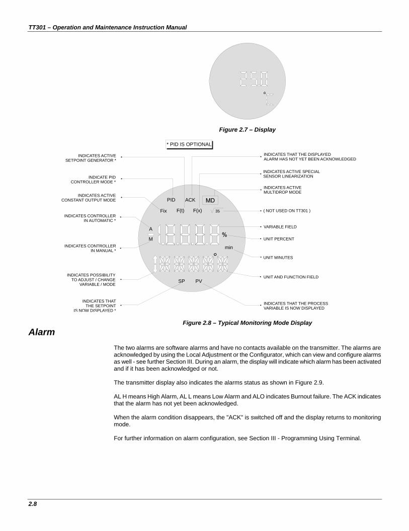
to display one or two variables which are user selectable. When two variables are chosen, the display will alternate between the two with an interval of 3 seconds. The different fields and status indicators are explained in Figure 2.7.
Monitoring During normal operation, the TT301 is in the monitoring mode. In this mode, indication alternates between the primary and secondary variable as configured in DISPLAY. See Figure 2.8.
The display indicates engineering units, values and parameters simultaneously with most status indicators. The monitoring mode is interrupted in two situations:
User performs complete local adju An alarm is activated.
The digital indicator is able
stment.
TT301 – Operation and Maintenance Instruction Manual
2.8
Figure 2.7 – Display
* PID IS OPTIONAL
M
A
Fix F(t)
PID
INDICATES THAT THE DISPLAYEDALARM HAS NOT YET BEEN ACKNOWLEDGED
INDICATES ACTIVE SPECIAL SENSOR LINEARIZATION
( NOT USED ON TT301 )
UNIT PERCENT
INDICATES THAT THE PROCESSVARIABLE IS NOW DISPLAYED
INDICATES ACTIVESETPOINT GENERATOR *
INDICATE PIDCONTROLLER MODE *
INDICATES ACTIVE CONSTANT OUTPUT MODE
INDICATES CONTROLLERIN AUTOMATIC *
INDICATES CONTROLLEIN MANUAL
INDICATES POSSIBILITTO ADJUST / CHANG
VARIABLE / MOD
INDICATES THATHE SETPOIN
I
SP
F(x) 35
PV
min
ACK
VARIABLE FIELD
UNIT MINUTES
UNIT AND FUNCTION FIELD
INDICATES ACTIVE MULTIDROP MODE
R *
YEE
TT
S NOW DISPLAYED *
Figure 2.8 – Typical Monitoring Mode Display Alarm
The two alarms are software alarms and have no contacts available on the transmitter. The alarms are acknowledged by using the Local Adjustment or the Configurator, which can view and configure alarms as well - see further Section III. During an alarm, the display will indicate which alarm has been activated and if it has been acknowledged or not. The transmitter display also indicates the alarms status as shown in Figure 2.9. AL H means High Alarm, AL L means Low Alarm and ALO indicates Burnout failure. The ACK indicates that the alarm has not yet been acknowledged. When the alarm condition disappears, the "ACK" is switched off and the display returns to monitoring mode. For further information on alarm configuration, see Section III - Programming Using Terminal.

Operation
2.9
ALARM 1
ALARM 2
Figure 2.9 – Typical Alarm Condition Display

TT301 – Operation and Maintenance Instruction Manual
2.10

Section 3
3.1
CONFIGURATION The Temperature Intelligent Transmitter TT301 is a digital device bearing the most advanced features a measurement apparatus can offer. A HART digital communication protocol permits the device to be connected to an external computer for a simple and complete configuration. These computers, connected to the transmitters, are called HOST computers and may be a Primary or Secondary Master type. Although HART may be a master/slave protocol, it may coexist with up to two masters in a field bus. Generally, the Primary HOST stands for a Supervisory and the Secondary HOST is used as a Configurator. Transmitters, on the other hand, may be connected to a point-to-point or a multi-drop network. In a point-to-point network, the equipment should have its address set at “0”, so that the output current is modulated from 4 to 20 mA, according to the measurement performed. In a multidrop network, the transmitters should be configured on a network address between “1” and “15”, if the identification devices work via address. In this case, the transmitter’s output current must be constant, each transmitter consuming 4 mA. If the identification mechanism is done via Tag, the transmitters may be addressed at “0” and control their current output, even on a multidrop configuration. The TT301 may be configured both for Transmitter and Controller and the HART addressing may be used as follows: TRANSMITTER MODE: The TT301 controls the current output, while the “1” to “15” addresses
adjust the TT301 on multidrop mode setting the output current control on 4 mA.
CONTROLLER MODE: The TT301 always controls the output current according to the value calculated for the Manipulated Variable, regardless of its address value on the net.
NOTE
When configured in multidrop for the classified areas the entity parameters allowed for the area must be strictly observed. So, verify that:
Ca ≥ Σ Cij + Cc La ≥ Σ Lij + Lc Voc ≤ min [Vmaxj] Isc ≤ min [Imaxj] Where: Ca, La = capacitance and inductance permitted in bus; Cij, Lij = transmitter capacitance and inductance r j (j=1, 155), without internal protection; Cc, Lc = cable capacitance and inductance; Voc = open circuit tension of the intrinsic safety barrier; Isc = short circuit tension of the intrinsic safety barrier; Vmax = maximum permissible tension to be applied on the r j transmitter; Imax = maximum permissible tension to be applied on the r j transmitter.
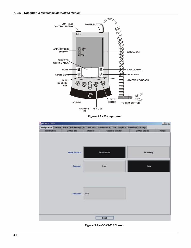
The TT301 Intelligent Temperature Transmitter presents a comprehensive set of HART Commands that permit accessing any implemented functionality. These commands comply with the HART protocol specifications and are grouped in Universal Commands, Common Practice Commands and Specific Commands. Smar developed the CONF401 and HPC301 software, the first one works in Windows platform (95, 98, 2000, XP and NT) and UNIX. The second one, HPC301, works in the most recent technology in PDA´s. They bring easy configuration and monitoring of field devices, capacity to analyze data and to modify the action of these devices. The operation characteristics and use of each one of the configurators are stated on their respective manuals.
Figures 3.1 and 3.2 show the front of the Palm and the CONF401 screen, with the active configuration.
TT301 - Operation & Maintence Instruction Manual
3.2
Figure 3.1 - Configurator
Figure 3.2 – CONF401 Screen
Programming Using Hand-Held Terminal
3.3
Configuration Resources Through the HART configurators, the TT301 firmware allows the following configuration resources to be accessed:
Transmitter Identification and Manufacturer Data; Primary Variable Trim – Temperature; Secondary Variable Trim – Terminal Temperature; Equipment Current Trim; Transmitter Adjustment to Work range; Engineering Unit Selection; Set Point Generator Configuration; PID Controller Configuration; Equipment Configuration; Equipment Maintenance. The operations occurring between the configurator and the transmitter do not interrupt the temperature measuring and do not disturb the output signal. The configurator may be connected on the same 4-20 mA signal cable to a maximum 2000 m distance from the transmitter.
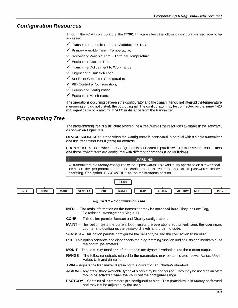
Programming Tree The programming tree is a structure resembling a tree, with all the resources available in the software, as shown on Figure 3.3. DEVICE ADDRESS 0: Used when the Configurator is connected in parallel with a single transmitter and this transmitter has 0 (zero) for address. FROM: 0 TO 15: Used when the Configurator is connected in parallel with up to 15 several transmitters and these transmitters are configured with different addresses (See Multidrop).
WARNING All transmitters are factory-configured without passwords. To avoid faulty operation on a few critical levels on the programming tree, the configuration is recommended of all passwords before operating. See option “PASSWORD”, on the maintenance section.
INFO CONF MAINT SENSOR PID RANGE TRIM ALARM FACTORY
TT301
MULTIDROP MONIT
Figure 3.3 – Configuration Tree
INFO – The main information on the transmitter may be accessed here. They include: Tag, Description, Message and Single ID.
CONF – This option permits Burnout and Display configurations MAINT – This option tests the current loop, resets the operations equipment, sees the operations
counter and configures the password levels and ordering code. SENSOR – This option permits configurate the sensor type and the connection to be used. PID – This option connects and disconnects the programming function and adjusts and monitors all of
the control parameters. MONIT – The user may monitor 4 of the transmitter dynamic variables and the current output. RANGE – The following outputs related to the parameters may be configured: Lower Value, Upper
Value, Unit and damping. TRIM – Adjusts the transmitter displaying to a current or an Ohm/mV standard. ALARM – Any of the three available types of alarm may be configured. They may be used as an alert
tool to be activated when the PV is out the configured range. FACTORY – Contains all parameters pre-configured at plant. This procedure is in-factory performed
and may not be adjusted by the user.

TT301 - Operation & Maintence Instruction Manual
3.4
MULTIDROP – The user may track the equipments connected to the loop, thus detecting their respective addresses. Also, an address is designated to each device to be connected to the network.
Identification and Manufacturing Data – Info
The main information on the transmitter may be obtained here. They are: Tag, Description, Message, Date and Single Identification. There is also a screen with important additional information on the equipment. They are: Manufacturer, Type of equipment, Serial Number and Transmitter Firmware Version, HART protocol Version and Hardware Revision.
The following information are available for the TT301 transmitter identification and manufacturer data:
TAG – Field with 8 alphanumerical characters for transmitter identification; DESCRIPTION – Field with 16 alphanumerical characters for additional transmitter identification; MESSAGE – Field with 32 alphanumerical characters for any other information, such as the name
of the last person to calibrate, some special caution to be observed or if a ladder is needed to access the transmitter, for example.
MODIFICATION DATE – The date may be used to identify a relevant date, as the last calibration, the next calibration or installation. The date is stored in the form of bytes, where DD = [1,..31], MM = [1..12], AA = [0..255] and the effective year is calculated by [ year = 1900 + AA];
UNIQUE ID* - Information for reading only.
*NOTE This item may not be modified.
Configurator - Conf
This function affects the transmitter 4-20 mA output and display reading. It may alter the lower and upper burnout, select the variables to be displayed and verify the status of writing protection. Burnout – The burnout may occur when the sensor reading is out of range or the sensor is open. In this case, the transmitter may be adjusted for maximum output limit at 21 mA, by configuring it on the upper value, or the minimum limit at 3.6 mA configured on the lower value.
Calibration – Range
The Lower and the Upper Values are calibrated in this operational range, which also selects the unit representing the process variable and the transmitter damping.
Maintenance - Maint The maintenance option offers the user 5 choices to check his loop functionality, such as: restart the equipment, test the current loop, verify the number of configurations performed, configure passwords and verify the equipment order code. Below is a brief description of the characteristics performed by the equipment Maintenance function: Device Reset – The equipment is switched off and then on. The restarting option should be carried out as a last resort, as it may destabilize the process control. Loop Test – The current output may be adjusted to any desired value between 3.8 and 21.0 mA regardless of the input value. There are a few stable current values for the loop test. The options available are: 4, 8, 16 or 20 mA. Operation Counter: The operation number counting is useful to indicate if somebody altered any configuration on the equipment. Every time one of the parameters below is altered, the respective alteration counter is activated. The monitored parameters are:
• Range configuration (Lower/Upper) • Change to Constant Current • 4 mA Trim • 20 mA Trim • Sensor Trim

Programming Using Hand-Held Terminal
3.5
• Burnout configuration • Sensor configuration • Auto/Manual shift (PID enabled) • Multidrop
Passwords: The options for password configuration and access level are: Info, Trim, Conf, Maint, PID and Alarm. There are three password levels. They are used to restrict the access to certain operations in the programming tree. In the default condition no password is configured. Each operation item may have a specified password level. The default password level is 0 (“Zero”), but the adjustment of Info at level “1” and Maint at level “3” are feasible. These levels may be altered by someone who knows the level “3” password. To cancel, just delete the current password and send another blank one. The level 3 password is hierarquically superior to the level 2 passwords, which, on its turn is superior to level 1. Ordering code – It contains the equipment ordering code.
NOTE Contact Smar in case you forgot or lost your password.
Sensor Types - Sensor It configures the TT301 input for the type of sensor in use and its connecting mode. The types covered in this manual are: RTD: Temperature Resistant Detector
Cu10 (GE) Ni120 (DIN) Pt50, 100, 500, 1000 (IEC) Pt50, 100 (JIS) Configurable for 2, 3 or 4 wires, differential, backup, maximum, minimum or average
TC: Thermocouples
B, E, J, K, N, R, S e T (NBS) L e U (DIN), K e S (IEC584) Configurable for 2, 3 or 4 wires, differential, backup, maximum, minimum or average
Ohm: Resistance Measuring 0 a 100 Ohm 0 a 400 Ohm 0 a 2000 Ohm Configurable for 2, 3 or 4 wires, differential, backup, maximum, minimum or average
mV: Voltage Measuring -6 a 22 mV -10 a 100 mV -50 a 500 mV Configurable for 2 wires, differential, backup, maximum, minimum or average
Special: Special Sensor Special Ohm Special mV
It is used for special sensors like charge cells or position resistive indicators. This resource may turn the TT301 into a mass, volume, position, etc. transmitter. Cold Junction: This option enables or not the cold junction for TC sensors. Do not use the "send" button. The alteration is made automatically in the transmitter.

TT301 - Operation & Maintence Instruction Manual
3.6
Conection and Work Model After the selection of the sensor type is necessary to choose the way how sensors work. The available options are: differential, 2 wires, 3 wires, 4 wires, backup, average, maximum and minimum. In the options 2, 3 or 4 wires, only one sensor is connected in the device terminal. In the options differential, backup, average, maximum and minimum are connected 2 sensors. 2, 3 and 4 wires: only one sensor will go to generate the process variable. If it ruptures, the burnout indication will be showed. Differential: In this mode, the TT301 will go to work with the measure difference between the sensors. If one of them to ruptures, the burnout indication will be showed. Backup: TT301 works with the reading of the first sensor (between 2 and 4 terminals). If this sensor brokes, the second sensor (between 3 and 4 terminals) will replace it and show the process variable reading. In this case, the reading of the first sensor will be discarded, even if this sensor returns to operate again. The first sensor will back to operate again if either gives it a reset by software or reenergize the device again. The message “S1BAD” will appear on LCD and the HART response code “Non-PV out of limits” is set. In case of failure of the second sensor, the transmitter will continue to operate normally but the message “S2BAD” will appear on LCD and the HART response code “Non-PV out of limits” will be set. Average: the final reading will be the average of the signals from two sensors. If the difference between them is higher than a programmed value, an alarm will be generated. If one of them ruptures, the other continues performing the process variable reading, and an alarm will be generated to inform this situation. The message “S1BAD” or “S2BAD” will appear on LCD and the HART response code “Non-PV out of limits” will be set. Maximum and minimum: the process variable will be supplied by sensor that has either maximum or minimum reading, respectively. If one of them ruptures, the other continues performing the process variable reading, and an alarm will be generate to inform this situation. The message “S1BAD” or “S2BAD” will appear on LCD and the HART response code “Non-PV out of limits” will be set.
Special Sensor Configuration The special sensor is a function that permits sensors whose typical curves are not stored in the TT301 memory to be used or linearized. Table 3.1 shows the available units for special sensors. Any sensor may be used, provided the TT301 accepts the signal range generated by the sensor. The Ohm and mV sensors limitations may be seen on table 3.2. To change the special sensor configuration select special on the sensor menu.
VARIABLE UNITS Pressure inH2O, InHg, ftH2O, mmH2O, mmHg, psi, bar, mbar, g/cm2, Pa, KPa,Ton, ATM
Volume Flow ft3/min, gal/min, l/minin, Gal/min, m3/h, gal/s, l/s, Ml/d. ft/3s, ft3/d, m3/s, m3/d, Gal/h, Gal/d, ft3/h, m3/min, bbl/s, bbl/min, bbl/h, bbl/d, gal/h, Gal/s, l/h
Speed ft/s, m/s, m/h Temperature ºC, ºF, ºR, K
Voltage mV, v Volume gal, l, Gal, m3, bbl, bush, Yd3, ft3, In3 Level & Length ft, m, in, cm, mm
Time min, sec, h, dia
Weight (Mass)
gram, Kg, Ton, lb, Shton, LTon
Mass Flow g/s, g/min, g/h, kg/s, kg/min, kg/h, kg/d, Ton/min, Ton/h, Ton/d, lb/s, lb/min, lb/h, lb/d, Ton/d
Temperature SGU, g/cm3, kg/m3, g/ml, kg/l, g/l, TWARD, BRIX, Baum H, Baum L, API, % Solw, % Solv, Ball
Others Ohm, Hz, mA, %, pH, µs, cPo Special 5 characters
Table 3.1 – Special Sensor Available Units

Programming Using Hand-Held Terminal
3.7
The sensor typical curve may be scheduled on the TT301 EEPROM memory as a 16-point table. These tables are usually supplied by the sensor manufacturer, but may also be obtained at a lab test.
WARNING The special sensor function may not be used when the setpoint generating function is being used and vice-versa.
The options for configuring the special sensor are:
Range – For the Ohm sensor there are 3 ranges: 0 to 100, 0 to 400 and 0 to 2000 ohm. For the mV sensor there are also 3 ranges: -6 to 22, -10 to 100 and –50 to 500.
Connection – There are 4 options: differential, two wires, three wires and four wires.
X and Y Tables – The special sensor table points are inserted here. The sensor input is stored as an X-variable. The chosen output is stored as a Y-variable (19999 ≤ Y ≤ +19999). The X-input should always have growing values. X = Ohm or mV terminal block input. Y = Chosen output in engineering units. Watch the following limitations for the X variable values:
CONNECTION TYPE 2, 3 OR 4 WIRES DIFFERENTIAL (each input)
Ohm 0 < X < 2000 0 < X < 1000 mV -6 < X < 500 10 < X < 250
Table 3.2 – Special Sensor Input Range
V.INF Calibration range lower limit. The least possible value for transmitter calibration when using this special sensor.
V.SUP Calibration range upper limit. The most possible value for transmitter calibration when using this special sensor.
Minimum Span The least possible span for transmitter calibration when using this special sensor.
Unit – Engineering Unit to be associated to the measured variable. If one from most of 100 units is selected, the respective HART protocol code will be attributed to this parameter. This way, the whole supervisory system having HART protocol may access the Unit menu.
PID This option adjusts the PID parameters including the Setpoint, change on auto/manual mode and the tuning parameters.
The TT301 with an activated PID works as a controller/transmitter, while, deactivated, it works only as a transmitter The transmitter 4/20mA output may become a PID controller output, following the equation below:
Where:
e = PV – SP (Direct) or SP – PV (Reverse) SP = Setpoint PV = Process Variable Kp = Proportional Gain Tr = Derivative Time MV = Output See below a list of configurations feasible on the PID function. PID Controller – ON/OFF Tuning Parameters – This feature configures the Kp, Tr and Td tuning parameters, as well as
output limits and rate.
+
+= ∫ dt
dPVTdedtTr
eKpMV .1

TT301 - Operation & Maintence Instruction Manual
3.8
PV, SP, MV and Error Readings – Provides real-time variable value. SP Tracking – When in MANUAL, the setpoint follows the PV. When the controller is switched to AUTO, the last PV value before the switch will be regarded as SP.
Control Action – This option configures the transmitter Operation Mode. The options are: Direct – The output increases when the PV rises. Reverse – The output decreases when the PV does. Control Mode – Selects Automatic and Manual. MV Configuration – Adjusts the manipulated variable. SP Configuration – The Setpoint is adjusted. Control Limits – This option switches the SP Power On to automatic, manual and last value. Safety value – The output after a power shortage or during a failure. Rate / Alteration – The maximum allowed output change. Lower Limit – The minimum allowed percent output. Upper Limit – The maximum allowed percent output. Setpoint Table – When the setpoint generator is activated, the setpoint varies according to a curve table. The time is always read in minutes and the setpoint in percentage. SP Generator – When activated, the setpoint varies with time according to the schedule on TABELA_SP table.
Monitoring - MONIT This function monitors the transmitter 4 dynamic variables and the output current on the configurator display simultaneously.
VARIABLE DESCRIPTION CORRENTE mA output.
*MV Output percent.
PV Process variable on the selected engineering unit.
TEMP °C Room temperature.
PV% Process variable percent.
*SP% Setpoint percent.
*SP Setpoint on the selected engineering unit.
*TIME Setpoint generator time in minutes.
*ER% Deviation between SP and PV percents.
Table 3.3 - Monitored Variables
The indications will always oscilate between the first and the second variable.
*NOTE
These items may only be selected on PID mode.
EXAMPLE
Set the first variable indication for PV percent and the second variable for current. If the display should not indicate the oscillation, select the same indication in both variables, or select “SEM” (“without”) on the second variable.

Programming Using Hand-Held Terminal
3.9
Calibrating the TT301 A transmitter calibration consists of configuring the input values related to 4 mA and 20 mA. The TT301 may do this in 4 different methods: 1 – By using the Configurator (no-reference method) whose calibration input is not required. 2 – By using the Configurator and an input signal as reference (referenced method). 3 – Local adjustment and an input signal as reference (simple local adjustment, with reference).
4 – Local adjustment and an input signal as reference (complete local adjustment, with reference). 5 – Local adjustment (complete local adjustment, without reference). In transmitter mode, the lower value always corresponds to 4 mA and the upper value to 20 mA. In PID mode, the lower value corresponds to PV=0 % and upper value to PV=100 %.
Calibration Without Reference The TT301 may be configured to supply 4 to 20 mA, the equivalent to the temperature limits on the user’s application, without the need to connecting a reference calibrating generator on its terminals. This is possible because the TT301has linearization curves for several standard temperature sensors in its memory. Let us suppose the transmitter range is calibrated from –100 to 300o C and one must calibrate it on 0 to 100o C. The transmitter generates a signal varying from 4 to 20 mA when the temperature oscillates between 0 and 100o C. Watch that both the LOWER and UPPER values are entirely independent. Adjusting one does not affect the other. However, the following rule must be observed: a) Both values should not be less than the lower limit or in excess of the upper calibration limit. b) The Upper value less Lower value span must be larger than the LOWER SPAN. If a signal needs to be reverted, i.e., have an UPPER VALUE smaller than the LOWER VALUE, proceed as follows: Make the inferior value as close as possible to the Superior Value or vice-versa, observing the allowed minimum span. Adjust the Superior Value with the desire value and, then, adjust the Inferior value. Example: If the transmitter is calibration such as: LOWER VALUE = 4 mA = 0 oC UPPER VALUE = 20 mA = 100 oC and the values should change to: LOWER VALUE = 4 mA = 100o C UPPER VALUE = 20 mA = 0o C; Considering that the Pt100 IEC Minimum Span is 10o C, the adjustments must be altered as follows: a) LOWER VALUE = 90, or 100-10. b) UPPER VALUE = 0 oC c) LOWER VALUE = 100 oC The table 3.4 shows graphycaly how to do this ranging.

TT301 - Operation & Maintence Instruction Manual
3.10
1 Step 2 Step 3 Step 4 StepGet sensor
minimum spanDo Lower
Value = 90 ºCDo Upper
Value = 0 ºC
100 ºCUpper Value
90 ºCUpper Value - Span
0 ºCLower Value
Minimum Span = 10 ºC
100 ºC
90 ºC
100 ºC
90 ºC
100 ºC
90 ºC
0 ºC 0 ºC0 ºC
Do Lower Value = 100 ºC
Lower Value
Lower Value Lower Value
Lower Value
Lower Value
st sd rd th
Upper Value Upper Value
Upper Value Upper Value
Table – 3.4 – Procedure to Range without Reference
Calibration With Reference This is the most convenient way to calibrate a transmitter. Apply the signal for adjusting the 4 mA point (PV=0 %). The Lower Value is altered but the span remains the same. The same procedure is applied for the Upper Value. LOWER VALUE = 0 Ohm UPPER VALUE = 100 Ohm Example: When measuring resistance the TT301 is calibrated as follows: After the installation is done, the potentiometer (input sensor) was found to have a 5 Ohm residual resistance when its indicator was on a zero position. The Lower Value reference trim quickly corrects this problem, causing the Lower Value to equal 5 Ohm. The Upper Value may be altered in the same way. As mentioned before, the Ohm or mV sensor input may differ a little from its plant standard. The Zero and Gain Trim may be used to adjust the transmitter reading to Engineering Units with its plant standard, thus eliminating possible differences.
Unit The Engineering Unit shown on the transmitter and the configurator displays may be altered. The units are linked to a selected process variable. The following units are available: - For mV input: always mV. - For Ohm input: always Ohm. - For Thermocouple and RTD: Celsius, Fahrenheit, Rankine and Kelvin degrees.
Damping The DAMPING option on the RANGE function enables electronic damping adjustment. The damping may be adjusted between 0 and 32 seconds.
Trim The TRIM function is used to adjust resistance, voltage and current reading to user standard. To continue the TRIM adjustment, the control loop must be on MANUAL to avoid disturbances in the process. There are two options: Current signal and input reading.

Programming Using Hand-Held Terminal
3.11
Current TRIM (4-20 mA output) When the microprocessor generates a 0 percent signal, the Digital-to-Analogic converter and related electronic circuits must emit a 4 mA output. If the signal is 100 percent, the output must be 20 mA. Differences may occur between the SMAR standard current and the plant standard. In this case, the current TRIM adjustment should be used. The Configurator will adjust the output signal and then it will ask again if the current is correct or not. Input Reading TRIM There may be differences between the SMAR resistance standard and mV and the plant standards. In this event, the user TRIM adjustment may be used. The TRIM available are: Zero trim, the Gain trim and Factory trim. - Zero Trim – Calibrates the resistance or millivoltage lower value. The zero trim does not interfere with the gain trim. - Gain Trim – Calibrates the resistance or milivoltage upper value. - Factory Trim – Recovers the Zero, Gain, and temperature sensor made in factory. For zero or gain adjustment, a resistance or mV standard should be connected with a better than 0.02% accuracy.
If the transmitter is configured as either differential sensor, backup, average, maximum or minimum, that is working with two sensors simultaneously, only the zero trim is available. To perform zero trim, it should to short circuit the two sensors in the field and to enter with the value 0 (zero). After perform the trim, remove the short circuit for the transmitter to read the sensors resistance without the influence of the lines. The line maximum resistance should be less than 32 Ω for that zero trim would be possible. Temperature Sensor Trim Althouth it is not necessary to perform the temperature trim of the terminal, it is possible a little adjustment in the temperature measure through this menu.
Alarm This function configures the three TT301 alarms, with independent configuration for alarms 1 and 2 action and limit. All the alarms may be monitored and identified through this function. Alarm zero indicates burnout and may be activated in this function. Rec - Recognizes the alarm, while the ACK indication on the transmitter display disappears as the pending alarms are identified. Action - Configures the alarm operation mode: low, high or off. Limit - Configures the level that the alarm is occurring.
Alarm Configuration Low - Is activated when the PV goes below the signal configured (decreasing). High - Is activated when the PV goes above the signal configured (increasing). Off - The alarm is disabled.
Online Multidrop Operation The multidrop connection is made up of several transmitters connected in parallel in a single communication line. The communication between the master system and the transmitters is digitally done, with the transmitter analog output deactivated (TRM mode) or activated (PID mode). The communication between the transmitters and the master system (PROG, DCS, data acquiring system or PC) is performed through a Bell 202 modem using a HART protocol. Each transmitter is identified by a single (1 to 15) address.

TT301 - Operation & Maintence Instruction Manual
3.12
The TT301 is produced with the address equal to zero, in a point-to-point operational mode. The transmitter communicates with the configurator by overlaying the communication on the 4-20 mA signals. To operate in multidrop mode, the transmitter address must switch to a 1 to 15. This change deactivates the 4-20 mA analog output by assuming the fixed value equal to 4 mA (TRM mode), or maintains the 4-20 mA variable when the equipment is configured for PID mode. When intrinsic safety is required, special attention must be laid on Ca, La parameters allowed for that area. To operate in multidrop mode, search for the transmitters connected on the same line. This operation is called “POLL” (“SEARCH”) and is automatically performed after "From 0 to 15" is selected and the “POLL” button activated on the Palm configurator screen below:
WARNING The output current is fixed on 4 mA as soon as the transmitter address is changed, except when the transmitter is configured for PID operation mode.
Configuration TT301 for Multidrop All equipments leave factory with a 0 (zero) address, unable to work in multidrop. To operate in multidrop they must be singly connected to any number between 1 and 15. To configure the transmitter in multidrop, connect it single on the line according to figure 1.6 on section 1. After powering it, press the HPC30pt icon. The configurator will display the following screen:
Select and option before searching for an address:
Equip. address
From: To:
Tag:..............
0
0 15
Figure 3.4 – Multidrop Configuration Screen
Select Equipment Address 0 on the first line and press the Poll button. When the configurator identifies the transmitter, select a line containing the information on the equipment. On next screen, choose the Multidrop option. Now, select the required transmitter address and press Send. See that no other required transmitter on same line has the same address, regardless of make, model and type. Repeat this procedure for all equipments connected in multidrop.
Multidrop Mode Configuration To use the configurator for communication with a specific transmitter in multidrop mode, select the second option From: 0 to 15 on the configurator screen and press the Poll button. When the configurator identifies a transmitter on the line, it will display a list with its Address, Tag and Manufacturer. After the transmitter is selected, the main menu with all configuration options will be displayed on the configurator for handling.

Section 4
PROGRAMMING USING LOCAL ADJUSTMENT
The Magnetic Tool Smar's magnetic tool is the second man-machine interface; it compromises the advantage of the powerful Smar Configurator and the convenience of the "good-old" tool. If the transmitter is fitted with a display, and is configured for complete - local - adjustment (using internal jumper) the magnetic tool is almost as powerful as the Configurator, eliminating the need for a Configurator in most basic applications. If the transmitter is not fitted with a display, or is configured for simple local adjustment (using internal jumper) the adjustment capability is reduced to reranging. To select the function mode of the magnetic switches configure the jumpers located at the top of the main circuit board as indicated below:
SI/COM OFF/ON NOTE WRITE PROTECT SIMPLE LOCAL ADJUSTMENT
COMPLETE LOCAL
ADJUSTMENT
Disables Disables Disables
1 Enables Disables Disables
2 Disables Enables Disables
Disables Disables Enables
NOTE If the hardware protection is selected, the EEPROM will be protected. The local adjustment default condition is simple enabled and write protect disabled.
ACTION / SPAN MOVE AROUND / ZERO
Figure 4.1 – Local Adjustment Switches The transmitter has, under the identification plate, holes for two magnetic switches activated by the magnetic tool. The holes are marked with Z (Zero) and S (Span). If "Simple Local Adjustment" is selected by the jumpers position, the switches have the following functions:
4.1

TT301 - Operation and Maintenance Instruction Manual
Transmitter mode: Z - It is used to select the Lower Range Value. S - It is used to select the Upper Range Value. They work exactly as the adjustment with reference of the Configurator controller mode for transmitters with digital display. Controller mode: Z - Moves the options (OPERATION and BATCH). S - Activates the selected function. If "Complete Local Adjustment" is selected by the jumpers position, the switches have the following functions: Z - Moves the options. S - Activates the selected function.
Reranging Using the Local Zero and Span Adjustments in Simple Mode It is possible to rerange the transmitter with the local adjustment switches located on the top of the electronic housing. The switches work like the adjustment "with reference" for the Configurator. In order to make these adjustments, the instrument must be configured as "transmitter" (XMTR). To adjust the zero of the transmitter, proceed as follows:
Apply the Lower Value, signal. Wait for the process to stabilize. Insert the magnetic tool in the ZERO adjustment hole (see Figure 4.2) Wait 2s. The transmitter should be reading 4 mA. Remove the tool.
Figure 4.2 – Local Zero and Span Adjustment
4.2

Programming Using Local Adjustment
Figure 4.3 - Local Adjustment Programming Tree – Main Menu As the reranging with reference, the span is maintained. In case you want to change the span, proceed as follows:
Apply the Upper Value, signal. Wait for the process to stabilize.
Insert the magnetic tool in the SPAN adjustment hole. Remove the tool.
Note that when zero adjustment is done, the URV can not be pushed above the URL. In this case, span is not maintained.
Complete Local Adjustment LOCAL PROGRAMMING TREE The programming tree is a tree-shaped structure with a menu of all available software resources, as shown in Figure 4.3. The Local Programming mode is entered by activating switch (Z). In transmitter mode, only the configuration branch of the tree is applicable, thus the first menu function will be UNIT.
WARNING
When programming using local adjustment, the transmitter will not prompt "Control loop should be in manual!" as it does when programming using the Configurator. Therefore it is a good idea, prior to configuration, to switch the loop to manual. And do not forget to return to auto after configuration is completed
OPER (OPERATION): Is the option where the operation related parameters of the controller are configured: Auto/ Manual, Setpoint, Manual output. BATCH: Is the option where the Setpoint generator related functions are operated: on/off, Pause, Reset and time adjustment. TUNE (TUNING): Is the option where the PID-Algorithm related parameters are configured: Action, Kp, Tr, and Td. CONF (CONFIGURATION): Is the option where the output and display related parameters are con-figured: unit, primary and secondary display, Lower and Upper Value, dam-ping, sensor type and operation mode. ESC (ESCAPE): Is the option used to go back to normal monitoring mode.
4.3

TT301 - Operation and Maintenance Instruction Manual
Operation [OPER]
Figure 4.4 – Local Adjustment Operation Tree
4.4
Z: Moves to the next branch (BATCH). S: Enters the OPERATION branch, starting with function AUTO/MANUAL.
Auto/Manual (A/M) Z: Moves to the SETPOINT INCREASE function. S: Toggles controller status, Automatic to Manual or Manual to Automatic. “A” and “M”indicates status.
Setpoint Adjustment (SP) Z: Moves to the SETPOINT DECREASE function. S: Increases the setpoint until the magnetic tool is removed or 100% is reached. Z: Moves to the MANIPULATED VARIABLE ADJUSTMENT function. S: Decreases the setpoint until the magnetic tool is removed or 0% is reached.
Manipulated Variable Adjustment (MV)
Z: Moves to the MANIPULATED VARIABLE DECREASE function. S: Increases the control output until the magnetic tool is removed or the upper output limit is reached. Z: Moves to the ACK function. S: Decreases the control output until the magnetic tool is removed or the lower output limit is reached.

Programming Using Local Adjustment
Acknowledge (ACK) Z: Moves the SAVE function. S: Acknowledges all alarms.
Save (SAVE)
Z: Moves to ESCAPE of the operation menu. S: Saves the setpoint and manual output values in the transmitter EEPROM, for use after power-on.
Escape (ESC)
Z: Moves to the AUTO/ MANUAL function. S: Escapes to the MAIN menu.
Batch [BATCH]
Figure 4.5 – Local Adjustment Batch Tree
Z: Moves to the TUNING branch. S: Enters the BATCH branch, starting with function SPGEN on/off.
Setpoint Generator On/Off (SPGEN)
Z: Moves to the SPGEN Pause/ Run function. S: Toggles setpoint generator. On to Off or Off to On.
Setpoint Generator Pause/Run (SPGEN)
Z: Moves to the RESET function. S: Toggles setpoint generator mode, pause to run or run to pause.
4.5

TT301 - Operation and Maintenance Instruction Manual
Reset (RESET) Z: Moves to the TIME INCREASE function. S: Resets the time register of the setpoint generator to 0.
Time (TIME) Z: Moves to the time decrease function. S: Increases the time register for the setpoint generator until the magnetic tool is removed or 19999 min. is reached. Z: Selects ESCAPE of the BATCH menu. S: Decreases the time register for the setpoint generator until the magnetic tool is removed or the time-base register is zero.
Escape (ESC) Z: Moves to the SPGEN on/off function. S: Escapes to the MAIN menu.
Tuning [TUNE]
Figure 4.6 – Local Adjustment Tuning Tree
Z: Moves to the CONFIGURA-TION branch. S: Enters the TUNING branch, starting with function KP-ADJUSTMENT.
4.6
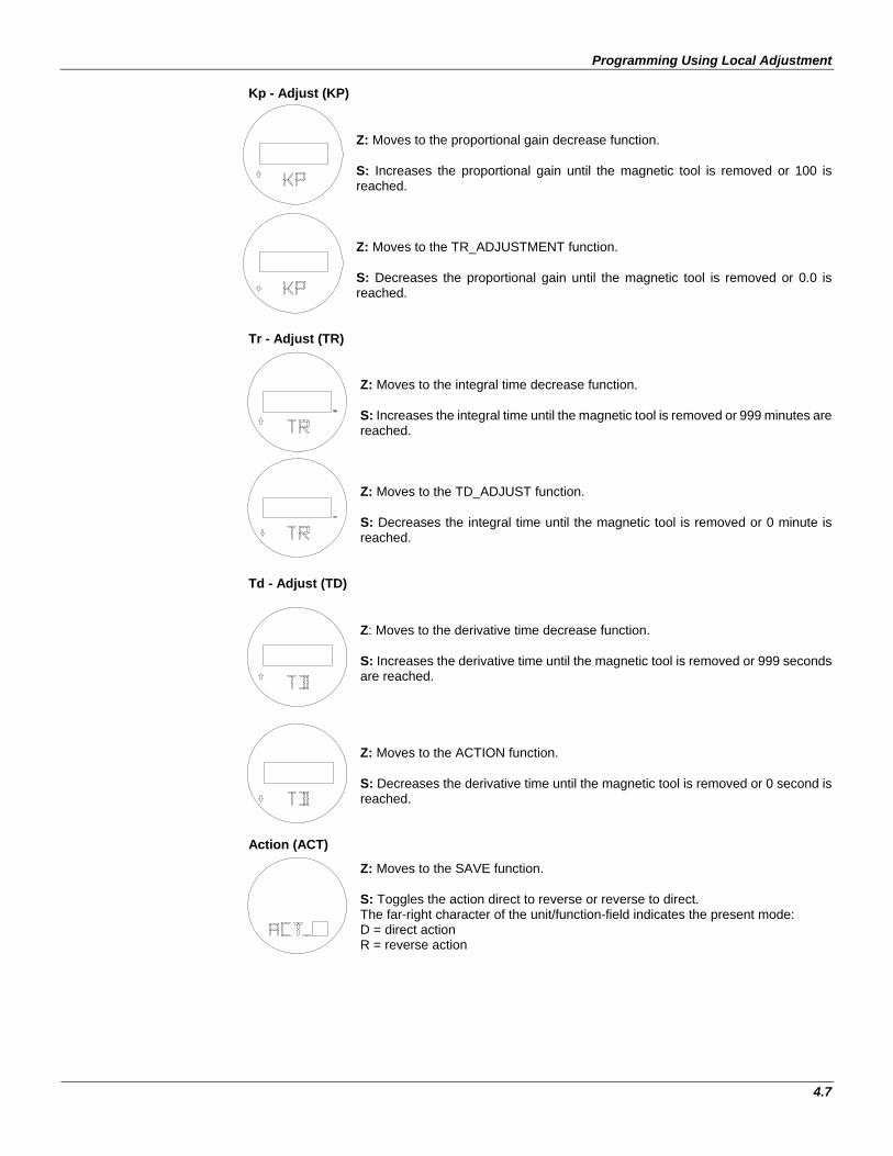
Programming Using Local Adjustment
Kp - Adjust (KP) Z: Moves to the proportional gain decrease function. S: Increases the proportional gain until the magnetic tool is removed or 100 is reached. Z: Moves to the TR_ADJUSTMENT function. S: Decreases the proportional gain until the magnetic tool is removed or 0.0 is reached.
Tr - Adjust (TR)
4.7
Z: Moves to the integral time decrease function. S: Increases the integral time until the magnetic tool is removed or 999 minutes are reached. Z: Moves to the TD_ADJUST function. S: Decreases the integral time until the magnetic tool is removed or 0 minute is reached.
Td - Adjust (TD)
Z: Moves to the derivative time decrease function. S: Increases the derivative time until the magnetic tool is removed or 999 seconds are reached. Z: Moves to the ACTION function. S: Decreases the derivative time until the magnetic tool is removed or 0 second is reached.
Action (ACT)
Z: Moves to the SAVE function. S: Toggles the action direct to reverse or reverse to direct. The far-right character of the unit/function-field indicates the present mode: D = direct action R = reverse action

TT301 - Operation and Maintenance Instruction Manual
Save (SAVE) Z: Moves to the ESCAPE to TUNING menu. S: Saves the KP, TR and TD constants in the transmitter EEPROM.
Escape (ESC)
Z: Moves to the KP-ADJUSTMENT function. S: Escapes to the MAIN menu.
4.8

Programming Using Local Adjustment
Configuration [CONF]
Figure 4.7 – Local Adjustment Configuration Tree
4.9

TT301 - Operation and Maintenance Instruction Manual
4.10
Z: Selects ESCAPE of the monitoring mode. S: Enters the CONFIGURATION branch, starting with function UNIT.
Unit (UNIT) Z: Moves to the DISPLAY-1 function. S: Starts selection of engineering unit for process variable and setpoint indication. After activating (S), you can move around the options available in the table below by activating (Z).
DISPLAY DESCRIPTION
C Degree Celsius F Degree Fahrenheit R Degree Rankine K Kelvin
mV millivolt Ohm Ohm SPEC Special Unit
NO No Unit ESC -escape-
The desired unit is activated by using (S). Escape leaves unit unchanged.
NOTE See special sensor in Section 3 for more information on “special unit”.
Display 1 (LCD_1)
Z: Moves to the DISPLAY-2 function. S: Starts selection of variable to be indicated as primary display. After activating (S), you can move around the options available in the following table by activating (Z).
DISPLAY DESCRIPTION
SP% Setpoint (%) PV% Process Variable (%) MV% Output (%) ER% Error (%)
Nothing TI SP generator time CU Output (mA) PV Process Variable (eng. unit) SP Setpoint (eng. unit)
ESC -escape- The desired variable is activated using (A). Escape leaves primary variable unchanged.

Programming Using Local Adjustment
NOTE In TRANSMITTER mode, only PV%, CU, PV and "none" are selectable.
Display 2 (LCD_2)
Z: Moves to the ZERO ADJUST function. S: Starts selection of variable to be indicated as secondary display. The procedure for selection is the same as for DISPLAY_1, above.
Lower Range Value Adjustment without Reference (LRV)
4.11
Z: Moves to the LRV decrease function. S: Increases the Lower Value until the magnetic tool is removed or the maximum for the Lower Value is reached. Z: Moves to the URV ADJUST-MENT function. S: Decreases the Lower Value until the magnetic tool is removed or the minimum for the Lower Value is reached.
Upper Range Value Adjust without Reference (URV)
Z: Moves to the URV decrease function. S: Increases the Upper Value until the magnetic tool is removed or the maximum for the Upper Value is reached. Z: Moves to the ZERO AD-JUSTMENT function. S: Decreases the Upper Value until the magnetic tool is removed or the minimum for the Upper Value is reached.
Reranging using the LRV and URV items in the menu is the same as the keyboard rerange on the CONFIGURATOR. No input has to be applied; the range is set independent of applied input. Adjust the value indicated on the display to the desired range value. Changing one does not affect the other. Zero Adjust with Reference (ZERO)
Z: Moves to the ZERO decrease function. S: Decreases the Lower Value (Increases output) until the magnetic tool is removed or the minimum for the Lower Value is reached. Z: Moves to the SPAN ADJUST function. S: Increases the Lower Value (Decreases Output) until the magnetic tool is removed or the maximum for the Lower Value is reached.
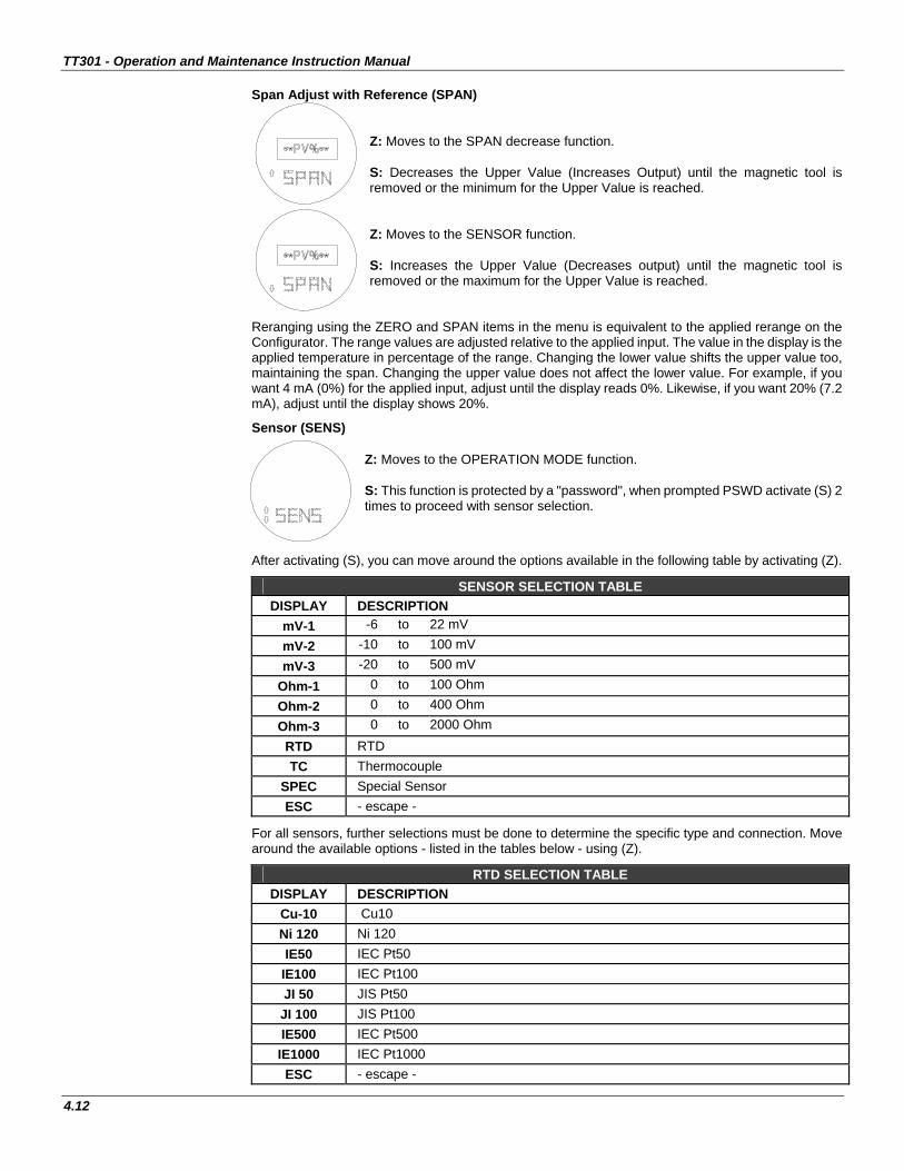
TT301 - Operation and Maintenance Instruction Manual
Span Adjust with Reference (SPAN) Z: Moves to the SPAN decrease function. S: Decreases the Upper Value (Increases Output) until the magnetic tool is removed or the minimum for the Upper Value is reached. Z: Moves to the SENSOR function. S: Increases the Upper Value (Decreases output) until the magnetic tool is removed or the maximum for the Upper Value is reached.
Reranging using the ZERO and SPAN items in the menu is equivalent to the applied rerange on the Configurator. The range values are adjusted relative to the applied input. The value in the display is the applied temperature in percentage of the range. Changing the lower value shifts the upper value too, maintaining the span. Changing the upper value does not affect the lower value. For example, if you want 4 mA (0%) for the applied input, adjust until the display reads 0%. Likewise, if you want 20% (7.2 mA), adjust until the display shows 20%.
Sensor (SENS)
4.12
Z: Moves to the OPERATION MODE function. S: This function is protected by a "password", when prompted PSWD activate (S) 2 times to proceed with sensor selection.
After activating (S), you can move around the options available in the following table by activating (Z).
SENSOR SELECTION TABLE DISPLAY DESCRIPTION
mV-1 -6 to 22 mV mV-2 -10 to 100 mV mV-3 -20 to 500 mV
Ohm-1 0 to 100 Ohm Ohm-2 0 to 400 Ohm Ohm-3 0 to 2000 Ohm
RTD RTD TC Thermocouple
SPEC Special Sensor ESC - escape -
For all sensors, further selections must be done to determine the specific type and connection. Move around the available options - listed in the tables below - using (Z).
RTD SELECTION TABLE DISPLAY DESCRIPTION
Cu-10 Cu10 Ni 120 Ni 120 IE50 IEC Pt50
IE100 IEC Pt100 JI 50 JIS Pt50 JI 100 JIS Pt100 IE500 IEC Pt500 IE1000 IEC Pt1000 ESC - escape -

Programming Using Local Adjustment
OHMS & RTD CONNECTION DISPLAY DESCRIPTION 2 WIRE 2 - wire 3 WIRE 3 – wire 4 WIRE 4 – wire
DIFF Differential ESC - escape -
THERMOCOUPLE - TYPE
DISPLAY DESCRIPTION B_NBS NBS type B E_NBS NBS type E J_NBS NBS type J K_NBS NBS type K N_NBS NBS type N R_NBS NBS type R S_NBS NBS type S T_NBS NBS type T L_DIN DIN type L U_DIN DIN type U ESC - escape -
Operation Mode (MODE)
Z: Moves to the SAVE function. S: This function is protected by a "password", when prompted PSWD activate (S) 2 times to proceed. After entering the "password", you can move around the options listed in the table below using (Z). In order to select the desired option, activate (S).
OPERATION MODE DISPLAY DESCRIPTION
XMTR Transmitter CNTRL Controller (Optional)
Save (SAVE)
Z: Selects ESCAPE to CONFIGURATION mode. S: Saves lower value and upper value.
Escape (ESC) Z: Moves to the UNIT function. S: Escapes to the MAIN menu.
4.13

TT301 - Operation and Maintenance Instruction Manual
ESCAPE [ESC] Z: Selects OPERATION branch. S: Escapes to MONITOR mode.
4.14

Section 5
5.1
MAINTENANCE PROCEDURES
General SMAR TT301 intelligent temperature transmitters are extensively tested and inspected before delivery to the end user. Nevertheless, during their design and development, consideration was given to the possibility of repairs by the end user, if necessary. In general, it is recommended that the end user do not try to repair printed circuit boards. Instead he should have spare circuit boards, which may be ordered from SMAR whenever necessary.
Diagnosis with Smar Configurator Should any problem be noticed related to the transmitter’s output, investigation may be carried out by the Configurator, as long as power is supplied and communication and the processing unit are operating normally. The programmer should be connected to the transmitter in accordance with the wiring diagram shown on Section 1, Figures 1.4, 1.5 and 1.8.
Error Messages When communicating using the Configurator the user will be informed about any problem found by the transmitters self diagnostics. As an example, the Configurator of the display may show:
> OUTPUT SATURATED <
The messages are always alternated with the information on the top line. The table below lists the error messages. Refer to trouble shooting for more details on corrective action.
Diagnostics with the Configurator
DIAGNOSTIC MESSAGES POTENTIAL SOURCE OF PROBLEM PARITY ERROR • Excessive noise or ripple. OVERRUN ERROR • Excessive noise or ripple. CHECK SUM ERROR • Excessive noise or ripple. FRAMING ERROR • Excessive noise or ripple.
NO RESPONSE
• The line resistance is not in accordance with load curve. • Transmitter not powered. • Interface not connected. • Transmitter configured in Multidrop mode being accessed by ON LINE SINGLE UNIT. • Transmitter reversely powered (polarity is reversed). • Interface damaged. • Power supply or battery voltage of the Configurator lower than 9 V.
LINE BUSY • Other device using the line.
CMD NOT IMPLEMENTED • Software version not compatible between Configurator and transmitter. • Configurator is trying to carry out a TT301 specific command in a transmitter from another manufacturer.
TRANSMITTER BUSY • Transmitter carrying out on important task. e.g., Local Adjustment. COLD START • Start-up or Reset due to power supply failure.
OUTPUT FIXED • Output in Constant Mode. • Transmitter in Multi-drop mode.

TT301 - Operation and Maintenance Instruction Manual
5.2
DIAGNOSTIC MESSAGES POTENTIAL SOURCE OF PROBLEM
OUTPUT SATURATED • Primary variable out of calibrated Span (Output current in 3.8 or 20.5 mA, XMTR mode only).
SV OUT OF LIMITS • Temperature out of operating limits. • Temperature sensor damaged.
PV OUT OF LIMITS
• Input signal out of operating limits. • Sensor damaged. • Transmitter with false configuration. • PV out of range limits (see table).
Table 1 - Diagnostics with the Configurator
Troubleshooting with Transmitter
Symptom: NO LINE CURRENT
Probable Source of Trouble:
Transmitter Connections
• Check wiring polarity and continuity.
• Check for shorts or ground loops.
Power Supply
• Check power supply output. The voltage at the TT301 terminals must be between 12 and 45 Vdc, and the ripple less than 0.4V.
Electronic Circuit Failure • Check the main board for defect by replacing it with a spare one.
Symptom: NO COMMUNICATION
Probable Source of Trouble:
Terminal Connections
• Check terminal interface connections.
• Check if the interface is connected to the points [COMM] and [-] or in the line between the transmitter and the load resistor.
• Check if the interface is model IF2 (for HART Protocol).
Transmitter Connections
• Check if connections are as per wiring diagram.
• Check line resistance; it must be equal to or greater than 250 Ohm, between the transmitter and the power supply.
Power Supply
• Check output of power supply. The voltage at the TT301 terminals must be between 12 and 45V, and ripple less than 0.4V.
Electronic Circuit Failure
• Locate the failure by alternately replacing the transmitter circuit and the interface with spare parts. Transmitter Address
• In On Line Multidrop item check if the address is "0".

Maintenance Procedures
5.3
Symptom: CURRENT OF 21.0 mA OR 3.6 mA Probable Source of Trouble: Transmitter Connection
• Check if the sensor is correctly connected to the TT301 terminal block. • Check if the sensor signal is reaching the TT301 terminal block by measuring it with a multimeter at
the transmitter-end. For mV and thermocouples test can be done with connected and disconnected to the transmitter.
Sensor
• Check the sensor operation; it shall be within its characteristics. • Check sensor type; it shall be the type and standard that the TT301 has been configured to. • Check if process is within the range of the sensor and the TT301.
NOTE
A 21.0 or 3.6mA current in XMTR mode indicates burnout.
Symptom: INCORRECT OUTPUT
Probable Source of Trouble:
Transmitter Connections
• Check power supply voltage. The voltage at the TT301 terminals must be between 12 and 45V, and ripple less than 0.4V.
• Check for intermittent short circuits, open circuits and grounding problems.
Noise, Oscillation
• Adjust damping • Check grounding of the transmitters housing, extra important for mV and thermocouple input. • Check the terminal block for moisture. • Check that the shielding of the wires between sensor/transmitter and transmitter/panel is grounded
only in one end.
Sensor
• Check the sensor operation; it shall be within its characteristics. • Check sensor type; it shall be the type and standard that the TT301 has been configured to.
Electronic Circuit Failure
• Check the integrity of circuit replacing it with a spare one.
Calibration
• Check calibration of transmitter.
Disassembly Procedure Refer to Figure 5.1. Make sure to disconnect power supply before disassembling the transmitter.
Sensor If the sensor is mounted on the transmitter, first disconnect the wires in order to prevent the wires from breaking. To access the terminal block, first loose the cover locking screw on the side marked "Field Terminals", then unscrew the cover.
Electronic Circuits The main board (6) and input board (9) are matched pairs and must be changed together and not mixed with others.
To remove the circuit boards (6 and 9) and display (4), first loose the cover locking (10) on the side not marked "Field Terminals" then unscrew the cover (1).
WARNING:
The board has CMOS components which may be damaged by electrostatic discharges. Observe correct procedures for handling CMOS components. It is also recommended to store the circuit boards in electrostatic-proof cases.

TT301 - Operation and Maintenance Instruction Manual
5.4
Loosen the two screws (5) that anchor the main circuit board. Gently pull out the main board (6). To remove the input board (9), first unscrew the two screws (8) that anchors it to the housing (11), gently pull out the board.
Reassembly Procedure • Put input board (9) into housing (11). • Anchor input board with its screws (8). • Put main board (6) into the housing, ensuring all inter connecting pins are connected. • Anchor main board with their screws (5). • Put display (4) into the housing, observing the four mounting positions (see Figure 5.2) "" symbol
should point in the direction desired as UP. • Anchor display with their screws (3). • Fit the cover (1) and lock it using the locking screw (10).
Interchangeability Calibration data is stored in the EEPROM of the main board, hence READING TRIM must be done if main-board or input board has been changed.
Returning Materials Should it become necessary to return the transmitter and/or Configurator to SMAR, simply contact your local agent or SMAR office, informing the defective instrument's serial number, and return it to our factory. In order to expedite analysis and solution of the problem, the defective item should be returned with a description of the failure observed, with as much details as possible. Other information concerning to the instrument operation, such as service and process conditions, is also helpful.
12
43
5
8
109
7
16
1314
1211
6
15
17
18
Figure 5.1 – Exploded View

Maintenance Procedures
5.5
ACCESSORY
ODERING CODE DESCRIPTION
SD-1 Magnetic Tool for local adjustment. Palm* 16 Mbytes Palm Handheld, Including HPC301’s initialization and installation software.
HPC301* HART® HPI311-M5P for the Palm, including the configuration package for the Smar and generic transmitters. HPI311-M5P* HART® interface.
* For equipment updates and HPC301 software, just check: http://www.smarresearch.com.
SPARE PARTS LIST FOR TRANSMITTER DESCRIPTION OF PARTS POSITION CODE CATEGORY
(NOTE1) HOUSING, Aluminum (NOTE 2) . 1/2 - 14 NPT 11 214-0200 . M20 x 1.5 11 214-0201 . PG 13.5 DIN 11 214-0202
HOUSING, 316 SS (NOTE 2) . 1/2 - 14 NPT 11 214-0203 . M20 x 1.5 11 214-0204 . PG 13.5 DIN 11 214-0205
COVER . Aluminum 1 and 18 204-0102 . 316 SS 1 and 18 204-0105
COVER WITH WINDOW FOR INDICATION . Aluminum 1 204-0103 . 316 SS 1 204-0106 COVER LOCKING SCREW 10 204-0120 EXTERNAL GROUND SCREW 15 204-0124 IDENTIFICATION PLATE FIXING SCREW 13 204-0116
DIGITAL INDICATOR 4 400-0559
TERMINAL HOLDER INSULATOR 14 214-0220
BOARD GROUP GLL1307 AND GLL1308 (DISPLAY AND ASSEMBLY KIT INCLUDED); TT301. 6 and 9 400-0865 A BOARD GROUP GLL1307 AND GLL1308 (DISPLAY AND ASSEMBLY KIT NOT INCLUDED); TT301. 6 and 9 400-0866 A
BOARD GROUP GLL1307 AND GLL1308 (WITHOUT DISPLAY AND WITH ASSEMBLY KIT INCLUDED); TT301. 6 and 9 400-0867 A
BOARD GROUP GLL1307 AND GLL1308 (INCLUDED DISPLAY AND WITHOUT ASSEMBLY KIT); TT301. 6 and 9 400-0868 A
ASSEMBLY KIT OF THE GROUP GLL1307 AND GLL1308; TT301 5, 7 and 8 400-0869 A
0-RINGS Cover, BUNA-N (NOTE 3) 2 204-0122 B
TERMINAL HOLDING SCREW 17 204-0119
CONDUIT PLUG
1/2 NPT Internal Socket Set Plug in Bichromatized Carbon Steel 16 400-0808
1/2 NPT Internal Socket Set Plug in 304 SST 16 400-0809 M20 X 1.5 External Socket Set Plug in 316 SST 16 400-0810
PG 13.5 External Socket Set Plug in 316 SST 16 400-0811
MAIN BOARD SCREW . Main board M3 x 0.5 x 25 mm screw (GLL895/959) - with indicator 5 204-0118 . Main board M3 x 0.5 x 5 mm screw (GLL895/959) - without indicator 5 204-0117 . Main board M3 x 0.5 x 20 mm screw (GLL1307/1308) - with and without indicator 5 400-1112 INPUT BOARD SCREW 8 214-0125
MOUNTING BRACKET FOR 2" PIPE MOUNTING (NOTE 4) . Carbon Steel ( Accessories in Carbon Steel ) - 214-0801 . Stainless Steel 316 (Accessories in Stainless Steel 316 ) - 214-0802 . Carbon Steel ( Accessories in Stainless Steel 316 ) - 214-0803 LOCAL ADJUSTMENT PROTECTION CAP 12 204-0114
NOTE 1 - For category A, it is recommended to keep, in stock, 25 parts installed for each set, and for category B, 50. 2 - It includes terminal holder insulator, bolts (cover lock, grounding and terminal holder insulator) and identification plate without certification. 3 - 0-Rings are packaged in packs of 12 units. 4 - Including U-clamp, nuts, bolts and washers.

TT301 - Operation and Maintenance Instruction Manual
5.6
Figure 5.2 – Four Possible Positions of the Display

Section 6
6.1
TECHNICAL CHARACTERISTIC
Functional Specifications
Inputs See table 6.1, 6.2 and 6.3
Output Signal Two-wire, 4-20 mA with superimposed digital communication (HART Protocol Version 5.1/Transmitter/Poll-Response mode/Common 4-20 mA).
Power Supply Bus powered: 12 - 45 Vdc.
Load Limitation
16501500
1000
500
012 20 30 40 45
250
Power Supply [ Volt ]
4-20mA only
Operating area
4-20mA and digitalcommunication
17
Display Optional 4 1/2 digit LCD indicator. Hazardous Area Certifications
Intrinsic Safety (FM, CSA, NEMKO, EXAM, CEPEL), Explosion Proof (FM, CSA, NEMKO, CEPEL), Dust Ignition Proof (FM), Non-incendive (FM)
European Directive Information
Authorized representative in European Community Smar Gmbh-Rheingaustrasse 9-55545 Bad Kreuzanach EMC Directive (2004/108/EC) – Electromagnetic Compa tibility The EMC test was performed according to IEC standard: IEC61326-1:2006, IEC61326-2-3:2006, IEC61000-6-4:2006, IEC61000-6-2:2005. For use only in industrial environment.
ATEX Directive (94/9/EC) – Equipment and protective systems intended for use in potentially explosive atmospheres. This product was certified according European Standards at NEMKO and EXAM (former DMT). The certified body for manufacturing quality assessment is EXAM (number 0158).
LVD Directive 2006/95/EC – Electrical Equipment des igned for use within certain voltage limits According the LVD directive Annex II the equipment under ATEX “Electrical equipment for use in an explosive atmosphere” directive are excluded from scope from this directive.
Zero and Span Adjustments No interactive, via digital communication or local adjustment.
Temperature Limits
Ambient: Storage: Display:
-40 ºC to 85 ºC -40 ºC to 120 ºC -20 ºC to 80 ºC -40 ºC to 85 ºC
(-40 ºF to 185 ºF) (-40 ºF to 248 ºF) (-4 ºF to 176 ºF) (-40 ºF to 185 ºF)
(without damage)
Loss of Input (Burnout)/Failure Alarm
In case of sensor burnout or circuit failure, the self diagnostics drives the output to 3.6 or to 21.0 mA, according to the user's choice.
Humidity Limits 0 to 100% RH Turn -on Time Performs within specifications in less than 10 seconds after power is applied to the transmitter.
Update Time Approximately 0.5 second.
Damping Adjustment User configurable from 0 to 32 seconds (via digital communication).
Configuration This is done by an external Configurator that communicates with the transmitter remote or locally using Hart Protocol. Locally the magnetic tool can be used as well. The magnetic tool can configure the majority of the items provided the transmitter is fitted with a display.
Performance Specifications Accuracy See tables 6.1, 6.2, 6.3 and 6.4.
Ambient Temperature Effect
For a 10 ºC variation: mV (- 6 to 22 mV), TC (NBS: B, R, S,T): ± 0.03% of the input milivoltage or 0.002 mV whichever is greater;
mV (- 10 to 100 mV), TC (NBS: E, J, K, N; DIN: L, U ): ± 0.03% of the input milivoltage or 0.01 mV whichever is greater;
mV (-50 to 500 mV): ± 0.03% of the input milivoltage or 0.05 mV whichever is greater;
Ohms (0 to 100 Ω), RTD (GE: Cu10): ± 0.03% of the input resistance or 0.01Ω whichever is greater;

TT301 – Operation and Maintenance Instruction Manual
6.2
Performance Specifications Ohms (0 to 400Ω), RTD (DIN: Ni120; IEC: Pt50, Pt100; JIS: Pt50, Pt100): ± 0.03% of the input resistance or 0.04 Ω whichever is greater;
Ohms (0 to 2000Ω), RTD (IEC: Pt500), RTD (IEC: Pt1000): ± 0.03% of the input resistance or 0.2 Ω whichever is greater;
TC: cold-junction compensation rejection 60:1 (Reference: 25.0 ± 0.3 °C). Power Supply Effect ± 0.005% of calibrated span per volt.
Vibration Effect Meets SAMA PMC 31.1. Electromagnetic Interference Effect
According to IEC61326-1:2006, IEC61326-2-3:2006, IEC61000-6-4:2006, IEC61000-6-2:2005.
Physical Specifications Electrical Connection 1/2 - 14 NPT, PG 13.5 DIN, and M20 X 1.5.
Material of Construction
Injected low copper aluminum with polyester painting or 316 Stainless Steel housing, with Buna N O’rings on cover (NEMA 4X, IP67).
Mounting Can be attached directly to the sensor. With an optional bracket can be installed on a 2" pipe or fixed on a wall or panel.
Approximate Weights
Without display and bracket mounting: 0.80 kg Add to the display: 0.13 kg Add to the bracket mounting : 0.60 kg
Control Characteristic
PID
PID. Proportional Gain: 0 to 100. Integral Time: 0.01 to 999 min/rep. Derivative Time: 0 to 999 s. Direct/Reverse Action. Lower and Upper output limits: -0.6 to +106.25%. Output rate-of-change limit: 0.02 to 600 %/s. Power-on safety output: -0.6 to +106.25%. Antireset windup. Bumpless Auto/Manual transfer. Setpoint Generator up to 16 points, up to 19999 minutes.
Alarm Dual, trip levels adjustable over entire range. High or Low action. Acknowledge message.
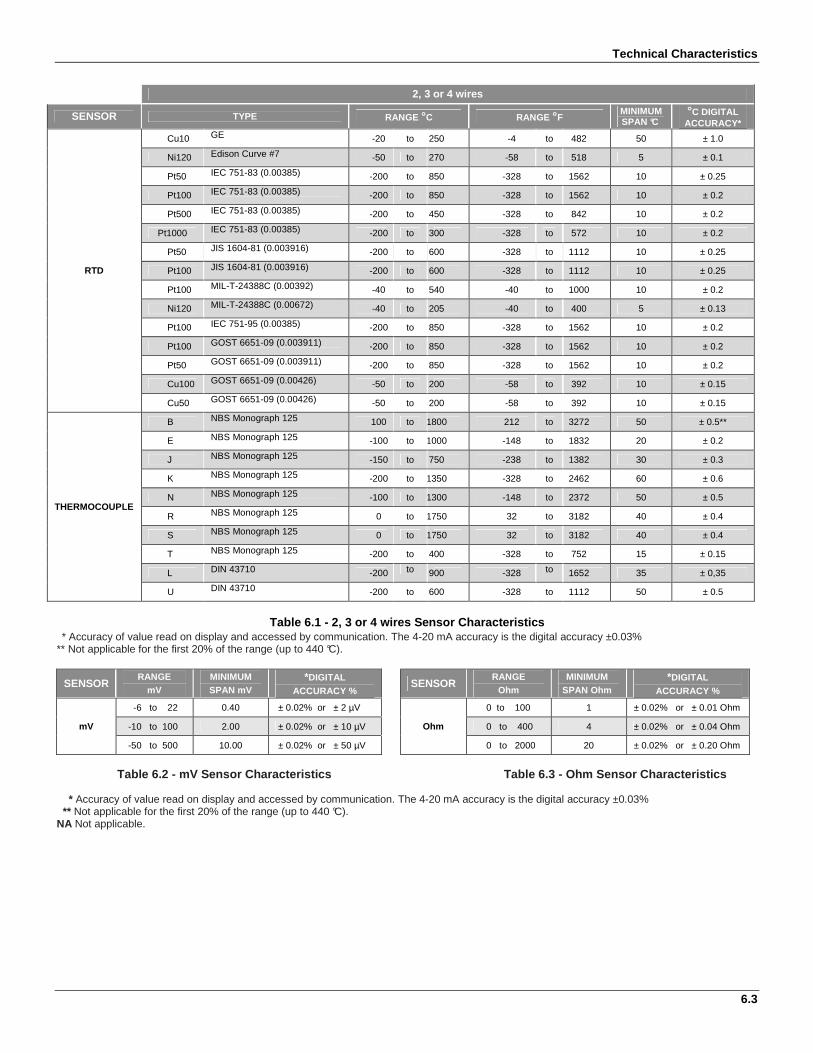
Technical Characteristics
6.3
2, 3 or 4 wires
SENSOR TYPE RANGE °C RANGE °F MINIMUM SPAN °C
°C DIGITAL ACCURACY*
RTD
Cu10 GE -20 to 250 -4 to 482 50 ± 1.0
Ni120 Edison Curve #7 -50 to 270 -58 to 518 5 ± 0.1
Pt50 IEC 751-83 (0.00385) -200 to 850 -328 to 1562 10 ± 0.25
Pt100 IEC 751-83 (0.00385) -200 to 850 -328 to 1562 10 ± 0.2
Pt500 IEC 751-83 (0.00385) -200 to 450 -328 to 842 10 ± 0.2
Pt1000 IEC 751-83 (0.00385) -200 to 300 -328 to 572 10 ± 0.2
Pt50 JIS 1604-81 (0.003916) -200 to 600 -328 to 1112 10 ± 0.25
Pt100 JIS 1604-81 (0.003916) -200 to 600 -328 to 1112 10 ± 0.25
Pt100 MIL-T-24388C (0.00392) -40 to 540 -40 to 1000 10 ± 0.2
Ni120 MIL-T-24388C (0.00672) -40 to 205 -40 to 400 5 ± 0.13
Pt100 IEC 751-95 (0.00385) -200 to 850 -328 to 1562 10 ± 0.2
Pt100 GOST 6651-09 (0.003911) -200 to 850 -328 to 1562 10 ± 0.2
Pt50 GOST 6651-09 (0.003911) -200 to 850 -328 to 1562 10 ± 0.2
Cu100 GOST 6651-09 (0.00426) -50 to 200 -58 to 392 10 ± 0.15
Cu50 GOST 6651-09 (0.00426) -50 to 200 -58 to 392 10 ± 0.15
THERMOCOUPLE
B NBS Monograph 125 100 to 1800 212 to 3272 50 ± 0.5**
E NBS Monograph 125 -100 to 1000 -148 to 1832 20 ± 0.2
J NBS Monograph 125 -150 to 750 -238 to 1382 30 ± 0.3
K NBS Monograph 125 -200 to 1350 -328 to 2462 60 ± 0.6
N NBS Monograph 125 -100 to 1300 -148 to 2372 50 ± 0.5
R NBS Monograph 125 0 to 1750 32 to 3182 40 ± 0.4
S NBS Monograph 125 0 to 1750 32 to 3182 40 ± 0.4
T NBS Monograph 125 -200 to 400 -328 to 752 15 ± 0.15
L DIN 43710 -200 to 900 -328 to 1652 35 ± 0,35
U DIN 43710 -200 to 600 -328 to 1112 50 ± 0.5
Table 6.1 - 2, 3 or 4 wires Sensor Characteristics
* Accuracy of value read on display and accessed by communication. The 4-20 mA accuracy is the digital accuracy ±0.03% ** Not applicable for the first 20% of the range (up to 440 °C).
SENSOR RANGE
mV MINIMUM SPAN mV
*DIGITAL ACCURACY %
SENSOR RANGE
Ohm MINIMUM
SPAN Ohm *DIGITAL
ACCURACY %
mV
-6 to 22 0.40 ± 0.02% or ± 2 µV
Ohm
0 to 100 1 ± 0.02% or ± 0.01 Ohm
-10 to 100 2.00 ± 0.02% or ± 10 µV 0 to 400 4 ± 0.02% or ± 0.04 Ohm
-50 to 500 10.00 ± 0.02% or ± 50 µV 0 to 2000 20 ± 0.02% or ± 0.20 Ohm
Table 6.2 - mV Sensor Characteristics Table 6.3 - Ohm Sensor Characteristics * Accuracy of value read on display and accessed by communication. The 4-20 mA accuracy is the digital accuracy ±0.03% ** Not applicable for the first 20% of the range (up to 440 °C). NA Not applicable.

TT301 – Operation and Maintenance Instruction Manua l
6.4
Ordering Code
MODEL TEMPERATURE TRANSMITTER
COD. Local Indicator (1) 0 Without Indicator 1 With Digital Indicator
COD. Mounting Bracket
0 1
Without Bracket Carbon Steel Bracket
2 7
316 SST Bracket Carbon Steel Bracket with 316 SST Fasteners
A
Flat, 304 SST bracket and 316 SST accessories
COD. Electrical Connections
0 1 2
1/2 - 14 NPT (3) 1/2 - 14 NPT X 3/4 NPT (316 SST) - With adapter (4) 1/2 - 14 NPT X 3/4 BSP (316 SST) - With adapter (2)
3 A B
1/2 - 14 NPT X 1/2 BSP (316 SST) - With adapter (2) M20 x 1.5 (5) PG 13.5 DIN (6)
Z According to user´s notes
COD. Housing Material (8) (9)
H0 H1 H2
Aluminum (IP/TYPE) 316 SST (IP/TYPE) Aluminum for saline atmosphere (IPW/TYPEX) (10)
H3 H4
316 SST for saline atmosphere (IPW/TYPEX) (10) Copper Free Aluminum (IPW/TYPEX) (10)
COD. Identification Plate
I1 I2
FM: XP, IS, NI, DI NEMKO: Ex-d, Ex-ia
I3 I4
CSA: XP, IS, NI, DI EXAM (DMT): Ex-ia; NEMKO: Ex-d
I5 I6
CEPEL: Ex-d, Ex-ia Without Certification
I7 IE
EXAM (DMT): Group I, M1 Ex-ia NEPSI: Ex-ia
COD. Tag Plate (7)
J0 J1
With tag, when specified (Default) Blank
J2 User specification
COD. Sensor Connection
L2 L3 L4
2-wire 3-wire 4-wire
LF LB
Differential Backup
COD. PID Configuration
M0 With PID (default) M1 Without PID
COD. LCD1 Indication Y0 Y1
Percentage (default) Current (mA)
Y3 YU
Temperature (Engineering unit) User specification
COD. LCD2 Indication Y0 Y4
Percentage (default) Current (mA)
Y6 YU
Temperature (Engineering unit) User specification
COD. Painting
P0 P3 P4 P5
Gray Munsell N 6,5 Polyester (Default) Black Polyester White Epoxy Yellow Polyester
P8 P9 PC
Without Painting Safety Blue Epoxy – Electrostatic Painting Safety Blue Polyester - Electrostatic Painting
COD. Sensor Type
T1 T2 T3 T4 T5 T6 T7 T8 T9 TA TB TC TD TE TF TG TH
RTD Cu10 - GE RTD Ni120 - DIN RTD PT50 - IEC RTD PT100 - IEC RTD PT500 - IEC RTD PT50 - JIS RTD PT100 - JIS 2K OHM 400 OHM Thermocouple type B - NBS Thermocouple type E - NBS Thermocouple type J - NBS Thermocouple type K - NBS Thermocouple type N – NBS Thermocouple type R - NBS Thermocouple type S - NBS Thermocouple type T - NBS
TK TP TN TO TQ TR TS TT TU TV TW TX 10 11 12 13
Thermocouple type L – DIN Thermocouple type U - DIN 100 OHM Special OHM 22 mV 100 mV 500 mV Special mV RTD PT1000 – IEC RTD PT100 - MILT RTD NI120 – MILT RTD PT100 – IEC RTD PT100 – GOST RTD PR50 – GOST CU100 – GOST CU50 - GOST
TT301 1 2 0 H1 I1 JO L2 M0 Y0 Y0 P8 T1
NOTE
(1) Values limited to 4 1/2 digits; units limited to 5 characters. (2) Options not certified for use in hazardous locations.
(3) Certified for use in hazardous locations (CEPEL, CSA, FM, NEMKO, EXAM) (4) Certified for use in hazardous locations (CEPEL, CSA, FM)
(5) Certified for use in hazardous locations (CEPEL, FM, NEMKO, EXAM)
(6) Certified for use in hazardous locations (CEPEL, NEPSI, EXAM)
(7) Rectangular plate in 316 SST. (8) IPX8 tested in 10 meters of water column for 24 hours.
(9) Ingress Protection:
Products CEPEL NEMKO / EXAM FM CSA NEPSI
TT300 IP66/68W IP66/68W Type 4X/6(6P) Type 4X IP67
(10) IPW/Type tested for 200 hours according to NBR 8094 / ASTM B 117 standard.

Appendix A
A.1
CERTIFICATIONS INFORMATION
European Directive Information
Authorized representative in European Community Smar Gmbh-Rheingaustrasse 9-55545 Bad Kreuzanach EMC Directive (2004/108/EC) – Electromagnetic Compatibility The EMC test was performed according to IEC standard: IEC61326-1:2006, IEC61326-2-3:2006, IEC61000-6-4:2006, IEC61000-6-2:2005. For use only in industrial environment. ATEX Directive (94/9/EC) – Equipment and protective systems intended for use in potentially explosive atmospheres. This product was certified according European Standards at NEMKO and EXAM (former DMT). The certified body for manufacturing quality assessment is EXAM (number 0158). LVD Directive 2006/95/EC – Electrical Equipment designed for use within certain voltage limits According the LVD directive Annex II the equipment under ATEX “Electrical equipment for use in an explosive atmosphere” directive are excluded from scope from this directive.
Other Certifications IP68 Report: Certifier Body: CEPEL
Tests for Ingress Protection IP68 – CEPEL DVLA – 7390/05C This report not applies to hazardous locations Ex d protection and with Drawing 101B-4740-00. For guarantee the ingress of protection IP68 in the electrical connection input with NPT thread must be applied a threadlocker like Loctite 262.
Documents for manuals:
• Label Plate: 101A-8823
Hazardous Locations Certifications
North American Certifications
FM Approvals
Certificate N: FM 3W0A4.AX Intrinsically Safe for use in Class I, Division 1, Groups A, B, C and D, Class II, Division 1, Groups E, F and G, Class III, Division 1; in accordance with entity requirements and control drawing 102A-0005. Entity parameter: Vmax = 30 Vdc Imax = 110 mA Ci = 5 nF Li = 8 uH. Non- incendive for Class I, Division 2, Groups A, B, C and D. Explosion-proof for Class I, Division 1, Groups A, B, C, and D; Dust-ignition proof for Class II and Class III, Division 1, Groups E, F, and G; hazardous locations. Ambient Temperature: (-20ºC < Tamb <+60ºC). Enclosure Type 4X/6 or Type4/6. Canadian Standards Association (CSA)
Certificate N: CSA1110996 Class 2258 02 Explosion Proof for Class I, Division 1, Groups B, C and D; Class II, Division 1, Groups E, F and G; Class III, Division 1; Class I, Division 2, Groups A, B, C and D; Class II, Division 2, Groups E, F and G; Class III, conduit seal not required.
Class 2258 03 Intrinsically Safe and Non-Incendive Systems for Class I, Division 1, Groups A, B, C and D; Class II, Division 1, Groups E, F and G; Class III, Division 1
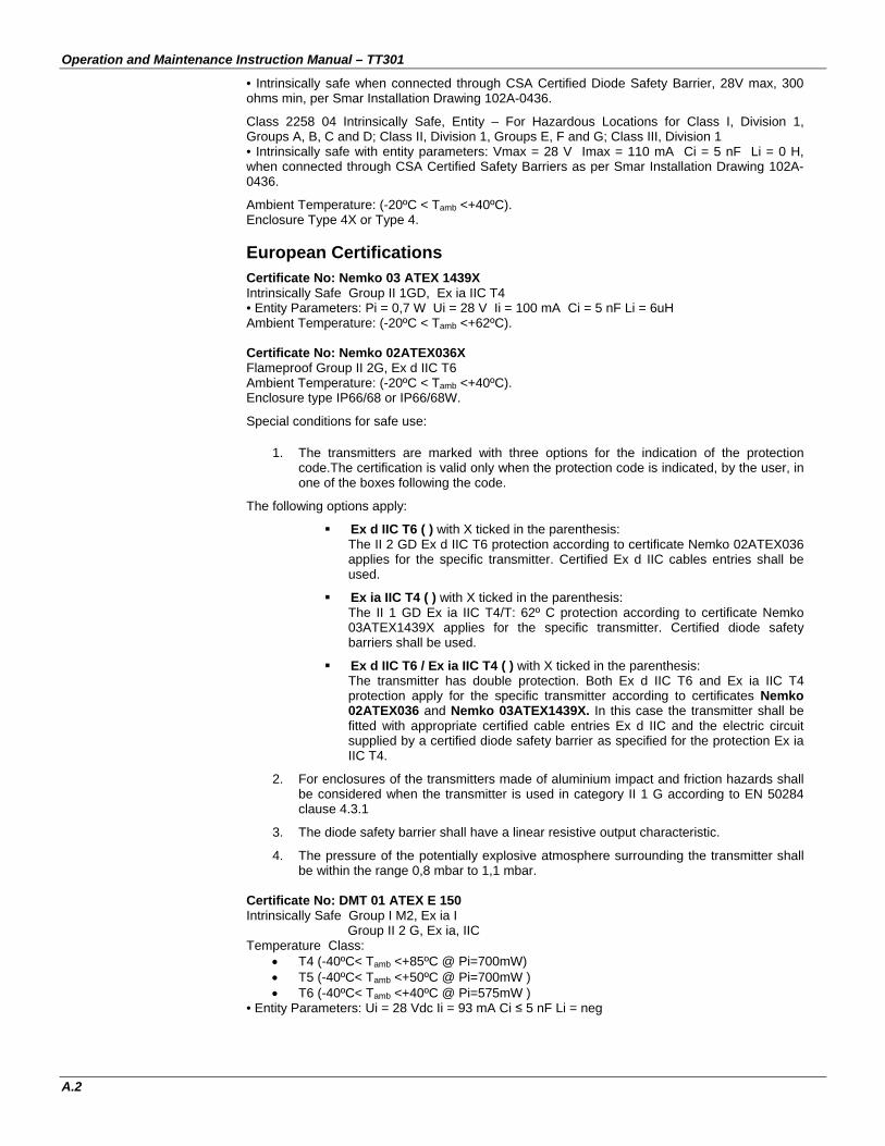
Operation and Maintenance Instruction Manual – TT301
A.2
• Intrinsically safe when connected through CSA Certified Diode Safety Barrier, 28V max, 300 ohms min, per Smar Installation Drawing 102A-0436.
Class 2258 04 Intrinsically Safe, Entity – For Hazardous Locations for Class I, Division 1, Groups A, B, C and D; Class II, Division 1, Groups E, F and G; Class III, Division 1 • Intrinsically safe with entity parameters: Vmax = 28 V Imax = 110 mA Ci = 5 nF Li = 0 H, when connected through CSA Certified Safety Barriers as per Smar Installation Drawing 102A-0436.
Ambient Temperature: (-20ºC < Tamb <+40ºC). Enclosure Type 4X or Type 4. European Certifications
Certificate No: Nemko 03 ATEX 1439X Intrinsically Safe Group II 1GD, Ex ia IIC T4 • Entity Parameters: Pi = 0,7 W Ui = 28 V Ii = 100 mA Ci = 5 nF Li = 6uH Ambient Temperature: (-20ºC < Tamb <+62ºC). Certificate No: Nemko 02ATEX036X Flameproof Group II 2G, Ex d IIC T6 Ambient Temperature: (-20ºC < Tamb <+40ºC). Enclosure type IP66/68 or IP66/68W.
Special conditions for safe use:
1. The transmitters are marked with three options for the indication of the protection code.The certification is valid only when the protection code is indicated, by the user, in one of the boxes following the code.
The following options apply:
Ex d IIC T6 ( ) with X ticked in the parenthesis: The II 2 GD Ex d IIC T6 protection according to certificate Nemko 02ATEX036 applies for the specific transmitter. Certified Ex d IIC cables entries shall be used.
Ex ia IIC T4 ( ) with X ticked in the parenthesis: The II 1 GD Ex ia IIC T4/T: 62º C protection according to certificate Nemko 03ATEX1439X applies for the specific transmitter. Certified diode safety barriers shall be used.
Ex d IIC T6 / Ex ia IIC T4 ( ) with X ticked in the parenthesis: The transmitter has double protection. Both Ex d IIC T6 and Ex ia IIC T4 protection apply for the specific transmitter according to certificates Nemko 02ATEX036 and Nemko 03ATEX1439X. In this case the transmitter shall be fitted with appropriate certified cable entries Ex d IIC and the electric circuit supplied by a certified diode safety barrier as specified for the protection Ex ia IIC T4.
2. For enclosures of the transmitters made of aluminium impact and friction hazards shall be considered when the transmitter is used in category II 1 G according to EN 50284 clause 4.3.1
3. The diode safety barrier shall have a linear resistive output characteristic.
4. The pressure of the potentially explosive atmosphere surrounding the transmitter shall be within the range 0,8 mbar to 1,1 mbar.
Certificate No: DMT 01 ATEX E 150 Intrinsically Safe Group I M2, Ex ia I Group II 2 G, Ex ia, IIC Temperature Class:
• T4 (-40ºC< Tamb <+85ºC @ Pi=700mW) • T5 (-40ºC< Tamb <+50ºC @ Pi=700mW ) • T6 (-40ºC< Tamb <+40ºC @ Pi=575mW )
• Entity Parameters: Ui = 28 Vdc Ii = 93 mA Ci ≤ 5 nF Li = neg

Certifications Information
A.3
South America Certification
INMETRO approvals
Certificate No: CEPEL-Ex-050/95 Intrinsically safe - Ex-ia IIC T5 • Entity Parameters: Ui = 30 Vdc Ii = 100 mA Ci =6,4nF Li = neg Pi=0,7W Ambient Temperature: (-20ºC < Tamb <+65ºC).
Certificate No: CEPEL-Ex-43/96-1 Flameproof - Ex-d IIC T6 Ambient Temperature: (-20ºC < Tamb<+40ºC). Enclosure IP66/68 or IP66/68W.
Identification Plate and Control Drawing
Identification Plate
• Identification for hazardous locations: FM
CSA
DMT and NEMKO

Operation and Maintenance Instruction Manual – TT301
A.4
CEPEL
WITHOUT APPROVAL
• Identification for hazardous locations for use in saline atmosphere: FM

Certifications Information
A.5
CSA
DMT and NEMKO
CEPEL

Operation and Maintenance Instruction Manual – TT301
A.6
Control Drawing
Factory Mutual (FM)

Certifications Information
A.7
NEMKO

Operation and Maintenance Instruction Manual – TT301
A.8
Canadian Standards Association (CSA)
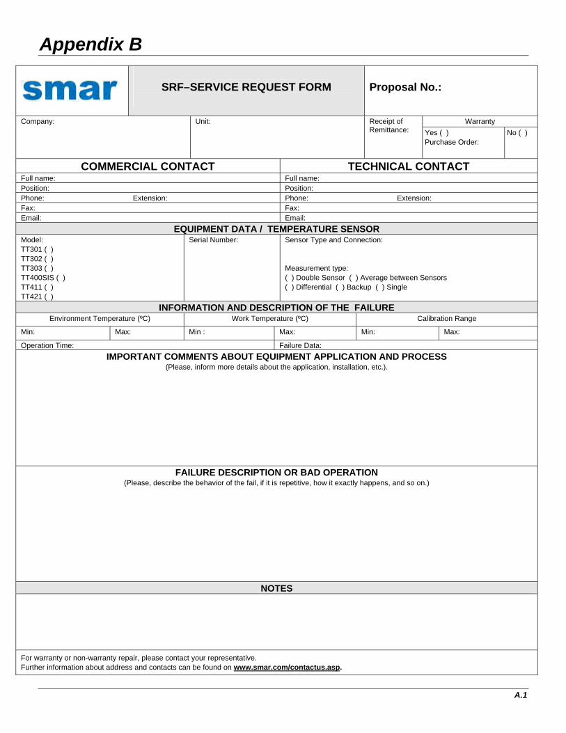
Appendix B
A.1
SRF–SERVICE REQUEST FORM
Proposal No.:
Warranty Company: Unit: Receipt of Remittance: Yes ( )
Purchase Order: No ( )
COMMERCIAL CONTACT TECHNICAL CONTACT Full name: Full name: Position: Position: Phone: Extension: Phone: Extension: Fax: Fax: Email: Email:
EQUIPMENT DATA / TEMPERATURE SENSOR Model: TT301 ( ) TT302 ( ) TT303 ( ) TT400SIS ( ) TT411 ( ) TT421 ( )
Serial Number: Sensor Type and Connection: Measurement type: ( ) Double Sensor ( ) Average between Sensors ( ) Differential ( ) Backup ( ) Single
INFORMATION AND DESCRIPTION OF THE FAILURE Environment Temperature (ºC) Work Temperature (ºC) Calibration Range
Min: Max: Min : Max: Min: Max:
Operation Time: Failure Data: IMPORTANT COMMENTS ABOUT EQUIPMENT APPLICATION AND PROCESS
(Please, inform more details about the application, installation, etc.).
FAILURE DESCRIPTION OR BAD OPERATION (Please, describe the behavior of the fail, if it is repetitive, how it exactly happens, and so on.)
NOTES
For warranty or non-warranty repair, please contact your representative. Further information about address and contacts can be found on www.smar.com/contactus.asp.

SRF – Service Request Form
A.2

Appendix C
C.1
SMAR WARRANTY CERTIFICATE 1. SMAR guarantees the equipment of its own manufacture for a period of 24 (twenty four)
months, starting on the day the invoice is issued. The guarantee is effective regardless of the day the product was installed. Third-party equipment and software are not included in this Term of Guarantee and Smar does not offer any guarantee or declaration in the name of the manufacturer. Any guarantees related to these products are the supplier or licenser responsibility.
2. SMAR products are guaranteed against any defect originating from manufacturing,
mounting, whether of a material or manpower nature, provided that the technical analysis reveals the existence of a quality failure liable to be classified under the meaning of the word, duly verified by the technical team within the warranty terms.
3. Exceptions are proven cases of inappropriate use, wrong handling or lack of basic
maintenance compliant to the equipment manual provisions. SMAR does not guarantee any defect or damage caused by an uncontrolled situation, including but not limited to negligence, user imprudence or negligence, natural forces, wars or civil unrest, accidents, inadequate transportation or packaging due to the user’s responsibility, defects caused by fire, theft or stray shipment, improper electric voltage or power source connection, electric surges, violations, modifications not described on the instructions manual, and/or if the serial number was altered or removed, substitution of parts, adjustments or repairs carried out by non-authorized personnel; inappropriate product use and/or application that cause corrosion, risks or deformation on the product, damages on parts or components, inadequate cleaning with incompatible chemical products, solvent and abrasive products incompatible with construction materials, chemical or electrolytic influences, parts and components susceptible to decay from regular use, use of equipment beyond operational limits (temperature, humidity, etc.) according to the instructions manual. In addition, this Warranty Certificate excludes expenses with transportation, freight, insurance, all of which are the customer’s responsibility.
4. For warranty or non-warranty repair, please contact your representative.
Further information about address and contacts can be found on www.smar.com/contactus.asp
5. In cases needing technical assistance at the customer’s facilities during the warranty
period, the hours effectively worked will not be billed, although SMAR shall be reimbursed from the service technician’s transportation, meals and lodging expenses, as well dismounting/mounting costs, if any.
6. The repair and/or substitution of defective parts do not extend, under any circumstance, the
original warranty term, unless this extension is granted and communicated in writing by SMAR.
7. No Collaborator, Representative or any third party has the right, on SMAR’s behalf, to grant
warranty or assume some responsibility for SMAR products. If any warranty would be granted or assumed without SMAR’s written consent, it will be declared void beforehand.
8. Cases of Extended Warranty acquisition must be negotiated with and documented by
SMAR. 9. If necessary to return the equipment or product for repair or analysis, contact us.
See item 4. 10. In cases of repair or analysis, the customer must fill out the Revision Requisition Form
(FSR) included in the instructions manual, which contains details on the failure observed on the field, the circumstances it occurred, in addition to information on the installation site and process conditions. Equipments and products excluded from the warranty clauses must be approved by the client prior to the service execution.
11. In cases of repairs, the client shall be responsible for the proper product packaging and
SMAR will not cover any damage occurred in shipment.

Smar Warranty Certificate
C.2
12. In cases of repairs under warranty, recall or outside warranty, the client is responsible for the correct packaging and packing and SMAR shall not cover any damage caused during transportation. Service expenses or any costs related to installing and uninstalling the product are the client´s sole responsibility and SMAR does not assume any accountability before the buyer.
13. It is the customer’s responsibility to clean and decontaminate products and accessories
prior to shipping them for repair, and SMAR and its dealer reserve themselves the right to refuse the service in cases not compliant to those conditions. It is the customer’s responsibility to tell SMAR and its dealer when the product was utilized in applications that contaminate the equipment with harmful products during its handling and repair. Any other damages, consequences, indemnity claims, expenses and other costs caused by the lack of decontamination will be attributed to the client. Kindly, fill out the Declaration of Decontamination prior to shipping products to SMAR or its dealers, which can be accessed at www.smar.com/doc/declarationofcontamination.pdf and include in the packaging.
14. This warranty certificate is valid only when accompanying the purchase invoice.