JCM Model Project “Power generation by ... - JCM …jcm.ekon.go.id/en/uploads/files/Document...
19
JCM Model Project “Power generation by waste heat recovery in cement industry” Gen TAKAHASHI Deputy General Manager Global Business Development 22 February 2016 22 February 2016 Reporting Meeting on JCM Projects and Feasibility Studies in JFY2015
Transcript of JCM Model Project “Power generation by ... - JCM …jcm.ekon.go.id/en/uploads/files/Document...

JCM Model Project “Power generation by waste heat
recovery in cement industry”
Gen TAKAHASHIDeputy General Manager
Global Business Development
22 February 201622 February 2016
Reporting Meeting on JCM Projects and Feasibility Studiesin JFY2015
2
About JFE Engineering
Project Summary
Project Methodology
Reference / Another JCM Project

Group Structure
5
43,000
Net Sales (million $)
Employees29,000
JFE Steel
6,000
Net Sales (million $)
Employees19,000
JFE Shoji Trade
JFE Holdings(holding company) 8,500
Net Sales (million $)
Employees3,700
JFE Engineering
6,000
Net Sales (million $)
Employees
3,600
Japan Marine United
Employees: 57,500
Turnover: 39 billion$
Fortune Global 500:
Ranked in 278
(FY2014) 3Copyright 2016 © JFE Engineering Corporation All Rights Reserved

Business Field
Net Sales(mil USD)
3,700 Energy Plant & PipelineSteel Structure
Environment
Industrial Machinery & Others
4Copyright 2016 © JFE Engineering Corporation All Rights Reserved
5
About JFE Engineering
Project Summary
Project Methodology
Reference / Another JCM Project
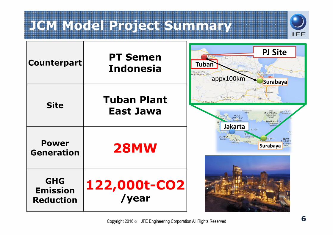
JCM Model Project Summary
6
CounterpartPT Semen Indonesia
SiteTuban PlantEast Jawa
Power Generation 28MW
GHGEmission Reduction
122,000t-CO2/year
Surabaya
Tuban
appx100km
Surabaya
Jakarta
PJ Site
Copyright 2016 © JFE Engineering Corporation All Rights Reserved
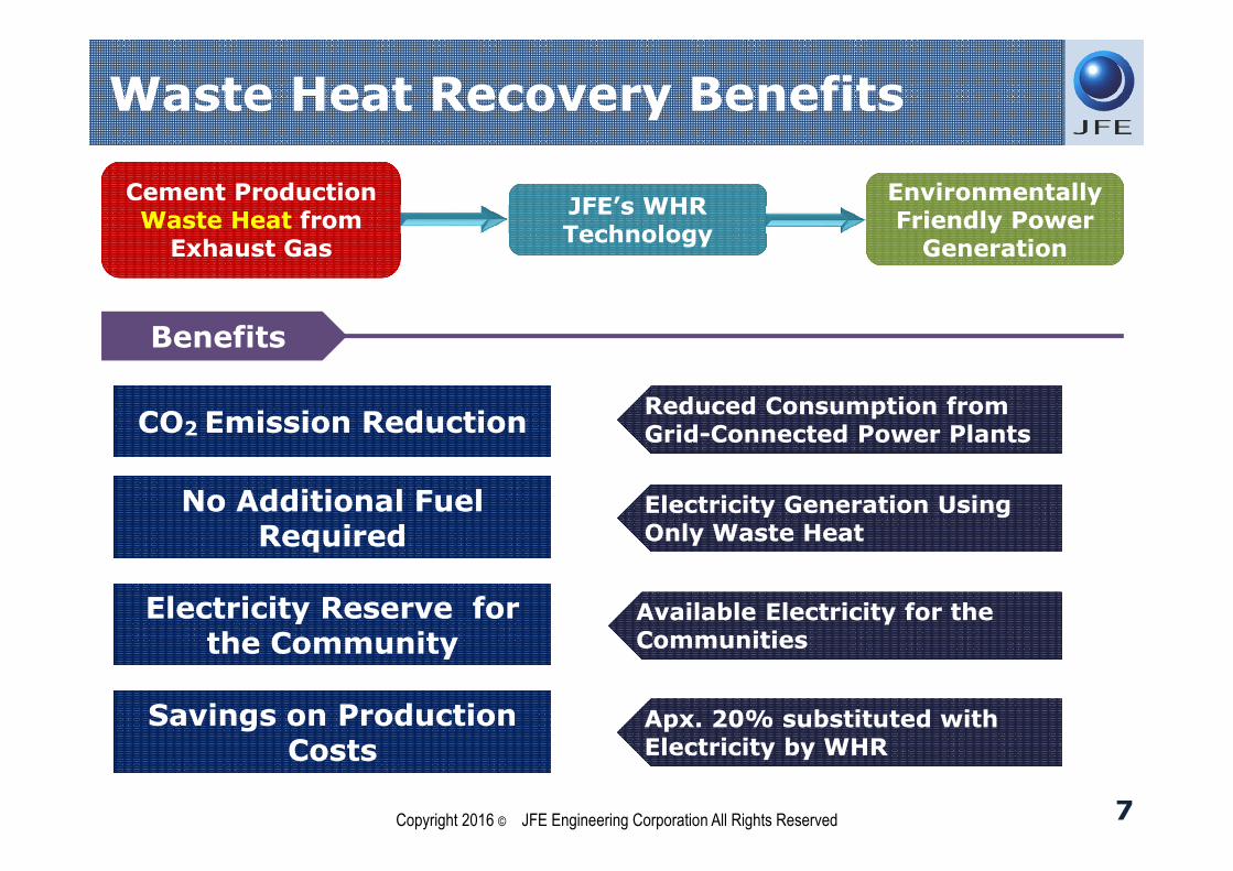
Waste Heat Recovery Benefits
7
Cement Production Waste Heat from
Exhaust Gas
Cement Production Waste Heat from
Exhaust Gas
Environmentally Friendly Power
Generation
Environmentally Friendly Power
Generation
JFE’s WHR TechnologyJFE’s WHR Technology
BenefitsBenefits
No Additional Fuel Required
No Additional Fuel Required
Savings on Production Costs
Savings on Production Costs
CO2 Emission ReductionCO2 Emission Reduction
Electricity Reserve for the Community
Electricity Reserve for the Community
Reduced Consumption fromGrid-Connected Power PlantsReduced Consumption fromGrid-Connected Power Plants
Electricity Generation Using Only Waste HeatElectricity Generation Using Only Waste Heat
Available Electricity for the CommunitiesAvailable Electricity for the Communities
Apx. 20% substituted with Electricity by WHRApx. 20% substituted with Electricity by WHR
Copyright 2016 © JFE Engineering Corporation All Rights Reserved
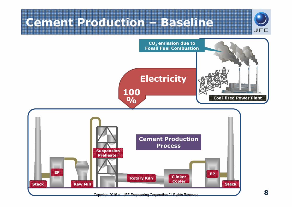
Cement Production – Baseline
8
Raw MillRaw MillStackStack
EPEPClinker CoolerClinker Cooler
EPEP
StackStack
Rotary KilnRotary Kiln
Suspension Preheater
Suspension Preheater
Cement Production Process
Cement Production Process
Coal-fired Power PlantCoal-fired Power Plant
Electricity
CO2 emission due to Fossil Fuel Combustion
CO2 emission due to Fossil Fuel Combustion
100%
Copyright 2016 © JFE Engineering Corporation All Rights Reserved
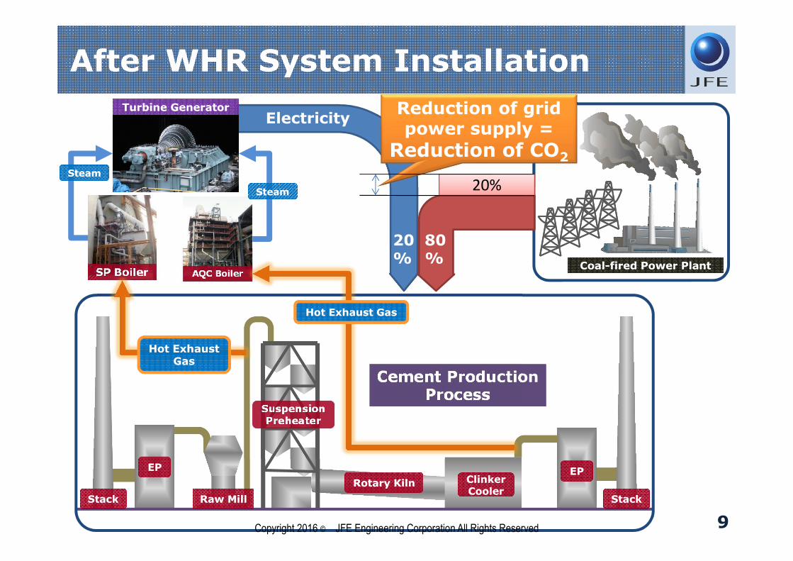
After WHR System Installation
9
Raw MillRaw MillStackStack
EPEPClinker CoolerClinker Cooler
EPEP
StackStack
Rotary KilnRotary Kiln
Suspension Preheater
Suspension Preheater
Cement Production Process
Cement Production Process
Coal-fired Power PlantCoal-fired Power Plant
Electricity
SP BoilerSP BoilerSP Boiler AQC BoilerAQC BoilerAQC Boiler
Turbine GeneratorTurbine Generator
Hot Exhaust Gas
Hot Exhaust Gas
Hot Exhaust GasHot Exhaust Gas
SteamSteam
SteamSteam
ElectricityReduction of grid power supply =
Reduction of CO2
20%
80%
20%
Copyright 2016 © JFE Engineering Corporation All Rights Reserved
10
About JFE Engineering
Project Summary
Project Methodology
Reference / Another JCM Project
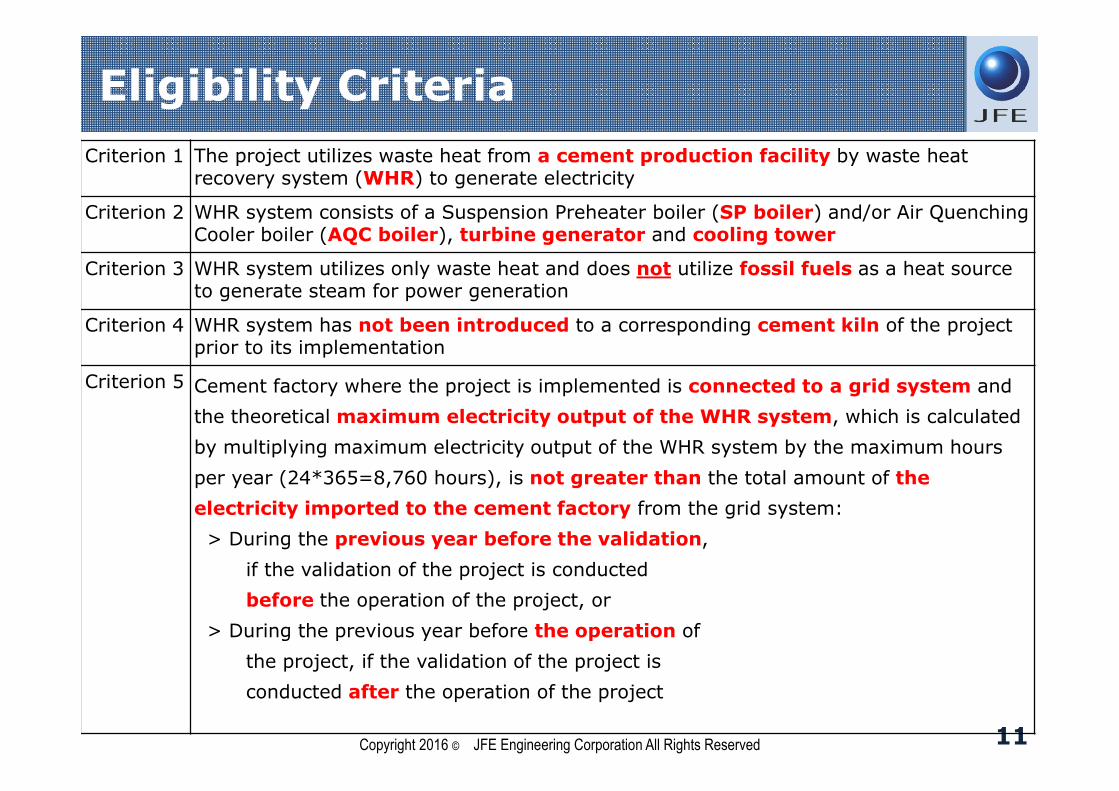
Eligibility Criteria
11
Criterion 1 The project utilizes waste heat from a cement production facility by waste heat recovery system (WHR) to generate electricity
Criterion 2 WHR system consists of a Suspension Preheater boiler (SP boiler) and/or Air Quenching Cooler boiler (AQC boiler), turbine generator and cooling tower
Criterion 3 WHR system utilizes only waste heat and does not utilize fossil fuels as a heat source to generate steam for power generation
Criterion 4 WHR system has not been introduced to a corresponding cement kiln of the project prior to its implementation
Criterion 5 Cement factory where the project is implemented is connected to a grid system and
the theoretical maximum electricity output of the WHR system, which is calculated
by multiplying maximum electricity output of the WHR system by the maximum hours
per year (24*365=8,760 hours), is not greater than the total amount of the
electricity imported to the cement factory from the grid system:
> During the previous year before the validation,
if the validation of the project is conducted
before the operation of the project, or
> During the previous year before the operation of
the project, if the validation of the project is
conducted after the operation of the project
Copyright 2016 © JFE Engineering Corporation All Rights Reserved
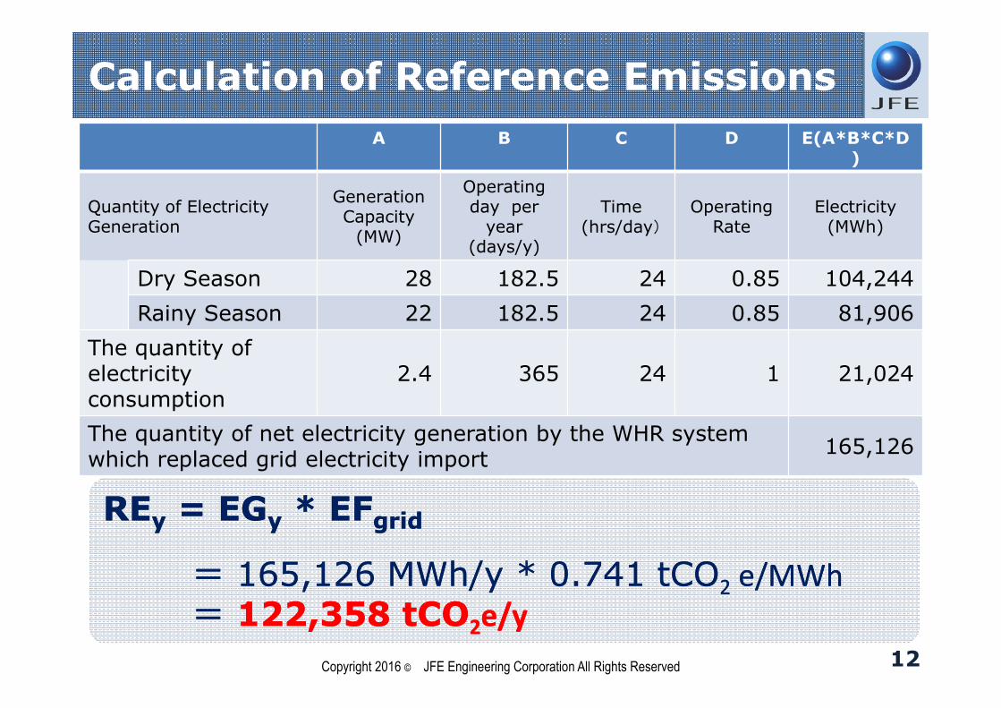
A B C D E(A*B*C*D)
Quantity of Electricity Generation
Generation Capacity
(MW)
Operating day per
year (days/y)
Time(hrs/day)
Operating Rate
Electricity(MWh)
Dry Season 28 182.5 24 0.85 104,244
Rainy Season 22 182.5 24 0.85 81,906
The quantity of electricity consumption
2.4 365 24 1 21,024
The quantity of net electricity generation by the WHR system which replaced grid electricity import
165,126
REy = EGy * EFgrid
= 165,126 MWh/y * 0.741 tCO2 e/MWh= 122,358 tCO2e/y
REy = EGy * EFgrid
= 165,126 MWh/y * 0.741 tCO2 e/MWh= 122,358 tCO2e/y
Calculation of Reference Emissions
12Copyright 2016 © JFE Engineering Corporation All Rights Reserved
Reference Emissions
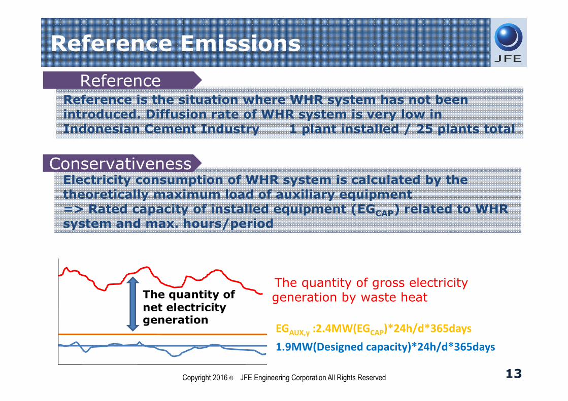
13
ConservativenessConservativenessElectricity consumption of WHR system is calculated by the theoretically maximum load of auxiliary equipment=> Rated capacity of installed equipment (EGCAP) related to WHR system and max. hours/period
ReferenceReferenceReference is the situation where WHR system has not been introduced. Diffusion rate of WHR system is very low in Indonesian Cement Industry 1 plant installed / 25 plants total
The quantity of net electricity generation
The quantity of gross electricity generation by waste heat
EGAUX,y :2.4MW(EGCAP)*24h/d*365days
1.9MW(Designed capacity)*24h/d*365days
Copyright 2016 © JFE Engineering Corporation All Rights Reserved

Reference Emissions
14
REy = EGy * EFgrid
REy: Reference emissionsEGy: The quantity of net electricity generationEFgrid: CO2 emission factor for an Indonesian regional grid system
Determination of EGy
EGy=EGGEN – EGAUX
EGGEN: The quantity of gross electricity generation by waste heatEGAUX: The quantity of electricity consumption by WHR system
Determination of EGAUX
EGAUX=EGCAP * 24 * 365EGCAP: The total maximum rated capacity of equipments of WHR system
Copyright 2016 © JFE Engineering Corporation All Rights Reserved
Emission Reduction / Monitoring
15
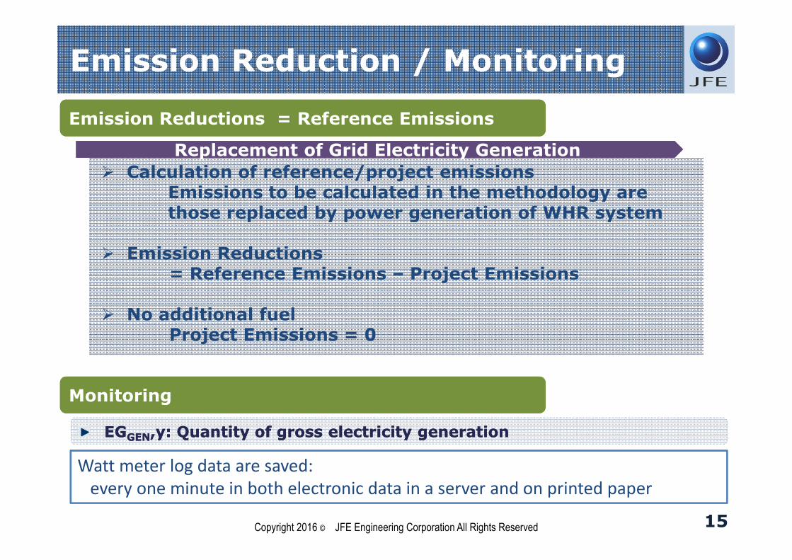
EGGEN,y: Quantity of gross electricity generationEGGEN,y: Quantity of gross electricity generation
Watt meter log data are saved:every one minute in both electronic data in a server and on printed paper
Copyright 2016 © JFE Engineering Corporation All Rights Reserved
Replacement of Grid Electricity GenerationReplacement of Grid Electricity Generation
Calculation of reference/project emissionsEmissions to be calculated in the methodology are those replaced by power generation of WHR system
Emission Reductions= Reference Emissions – Project Emissions
No additional fuelProject Emissions = 0
Emission Reductions = Reference Emissions Emission Reductions = Reference Emissions
MonitoringMonitoring
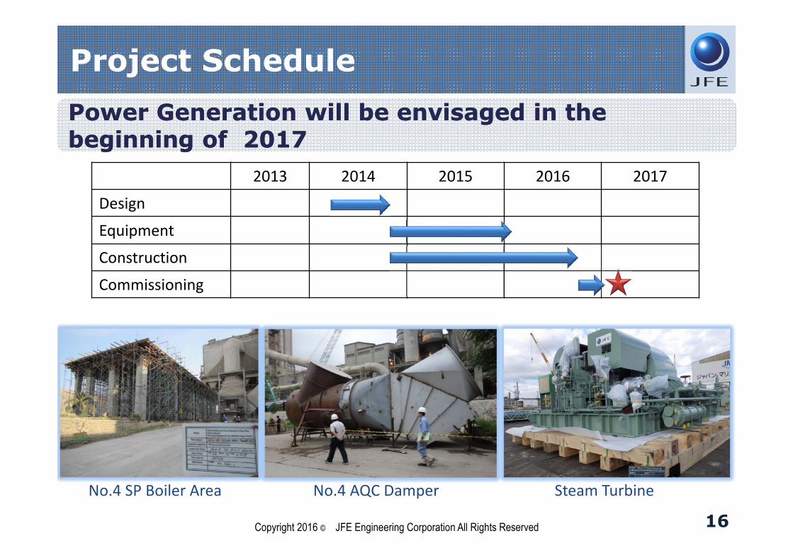
Project Schedule
16
Power Generation will be envisaged in the beginning of 2017Power Generation will be envisaged in the beginning of 2017
2013 2014 2015 2016 2017
Design
Equipment
Construction
Commissioning
Copyright 2016 © JFE Engineering Corporation All Rights Reserved
No.4 SP Boiler Area No.4 AQC Damper Steam Turbine
17
About JFE Engineering
Project Summary
Project Methodology
Reference / Another JCM Project

Waste to Energy Plant in Yangon- JCM Model Project -
Image
CounterpartYangon City Development
Committee
SiteMingalardon area, Yangon City,
MYANMAR
TechnologyWaste to Energy(WTE)Incinerator : 60ton/day
Generator : 0.7MW
GHG Emission Reduction
4,700t-CO2/year
First WTE Project with JCM
First WTE Project in Myanmar
Ground Breaking Ceremony on Oct. 10th 2015
18Copyright 2016 © JFE Engineering Corporation All Rights Reserved

19
Thank you for your kind attention.
JFE Engineering Corporation (Tokyo Head Office)Marunouchi Trust Tower North 19F, 1-8-1 Marunouchi, Chiyoda-ku, Tokyo 100-0005, JAPANTEL:+81-3-62120822 FAX:+81-3-62120803PT. JFE Engineering IndonesiaSentral Senayan Ⅲ 13th Floor, Jl. Asia Afrika No.8, Gelora Bung Karno - Senayan, Jakarta Pusat 10270, INDONESIATEL:+62-21-29660785 FAX:+62-21-29660788