IV-I7. Torsional Analysis of Coupled Shear Walls
4
340 Vth International Brick Masonry Conference IV-I7. Torsional Analysis of Coupled Shear Walls S. R. Davies and O. Keskin Department o[ Civil Engineering and Building Science, University o[ Edinburgh ABSTRACT In a previous publication the authors have developed an approach to the problem o[ torsion in multi-storey structures and compared their results with those obtained by other methods both theoretical and experimental. For the examPle considered it was slwwn that better agreement was obtained between theoretical and experimental results i[ the slab effect was not included. In this paper the authors illustmte the aPPlication o[ the method to the solution o[ a simPle cTOss -wall brickwork structure which was previously investigated by Kalita and H endry, Coull and Irwin and Tso. The theoretical results for rotation obtained by lhe aulhors and other researchers are compared with the experimental values obtained by Kalita and H endry. INTRODUCTION In previous publications s . 6 the authors have described the experimental results obtained for rotations and deflections due to eccentric loading on a multi-storey blockwork struc- t ure. Also included was a theoretica l approach for analysing such structures and comparisons between experimental and theoretica l results which showed reasonable agreement. The cross-section of the test structure, which had been selected because of availability, consisted of a symmetrical arrangement of rectangles and equal angles so that the warping effect reduced theoretically to zero and, as a result, the influence of the effect of warping could not be deter- mined for the more general case. In addition the theoretical resu lts calculated with and without the contribution of the floor slabs to the overall stiffness indicated that the slab stiffness was being overes- timated so that the measured rotations were larger than the theoretical when the slab effect was included. In this paper the analysis is applied to an arrangement of masonry channel sections, connected by floor slabs, for which the warping effect does not reduce to zero . Previous workers' · 2." have also used this type of channel core section for the development of their theories and the results of their analyses together with the experimental val- ues obtained by Kalita" are available for comparison. An opportunity is therefore provided for the estimation of the influence of both the warping and slab effects on this type of construction. BASIC EQUATIONS The basic equations for the rotation at any section is derived by considering lhe equilibrium of the externa i twisting mo- ment (M T ) and the internai twisting moments. The internai moments can be conveniently separated into four parts, the first three being contributed by the individual walls and the fourth by the floor slab. 1. The St. Venant Torsion (M,J 2. The Warping Contribution (MJ 3. The moment due to shear forces acting about the shear centres (M,) 4. The moments carried by the floor slabs (M,) Starting with (1) and introducing the necessary boundary conditions it can be shown that, for a concentrated torque 9 = [-yz - Sinh(l'z) + Tanh(I'H)(Cosh(l'z) and for a distributed torque 9 = ([ Tanh(I'H) + (I'z) - 1) I'Z . } mTH + -(2H - Z) - Smh(l'z) -,- o 2H yEC (3) Once the rotation 9 has been calculated the deflection of the structure, and the stresses over the cross-section can be calculated. The St. Venant Torsion The St. Venant theory was originally applied to circul ar shafts and assumes that the twisting at any cross section produces on ly shear stresses. It has been applied to sections which are made up of several rectangles and can be ex- pressed as (4) where s; and t; represent the lengths and thickness of the n rectangles forming the section. The Warping Effect The warping effect can be expressed as d'9 d:l9 L:I M". = E -d :I I" = E -d" oo"(s)t ds z- Z' () (5) where 00 represents the sectional co-ordinate introduced by Vlasov' (Fig. 3). .
Transcript of IV-I7. Torsional Analysis of Coupled Shear Walls
340 Vth International Brick Masonry Conference
IV-I7. Torsional Analysis of Coupled Shear Walls S. R. Davies and O. Keskin
Department o[ Civil Engineering and Building Science, University o[ Edinburgh
ABSTRACT
In a previous publication the authors have developed an approach to the problem o[ torsion in multi-storey structures and compared their results with those obtained by other methods both theoretical and experimental. For the examPle considered it was slwwn that better agreement was obtained between theoretical and experimental results i[ the slab effect was not included.
In this paper the authors illustmte the aPPlication o[ the method to the solution o[ a simPle cTOss-wall brickwork structure which was previously investigated by Kalita and H endry, Coull and Irwin and Tso. The theoretical results for rotation obtained by lhe aulhors and other researchers are compared with the experimental values obtained by Kalita and H endry.
INTRODUCTION
In previous publicationss.6 the authors have described the experimental results obtained for rotations and deflections due to eccentric loading on a multi-storey blockwork structure. Also included was a theoretical approach for analysing such structures and comparisons between experimental and theoretical results which showed reasonable agreement.
The cross-section of the test structure, which had been selected because of availability, consisted of a symmetrical arrangement of rectangles and equal angles so that the warping effect reduced theoretically to zero and, as a result, the influence of the effect of warping cou ld not be determined for the more general case.
In addition the theoretical results calculated with and without the contribution of the floor slabs to the overall stiffness indicated that the slab stiffness was being overestimated so that the measured rotations were larger than the theoretical when the slab effect was included.
In this paper the analysis is applied to an arrangement of masonry channel sections, connected by floor slabs, for which the warping effect does not reduce to zero .
Previous workers' ·2." have also used this type of channel core section for the development of their theories and the results of their analyses together with the experimental values obtained by Kalita" are available for comparison. An opportunity is therefore provided for the estimation of the influence of both the warping and slab effects on this type of construction.
BASIC EQUATIONS
The basic equations for the rotation at any section is derived by considering lhe equilibrium of the externai twisting moment (MT ) and the internai twisting moments. The internai moments can be conveniently separated into four parts, the first three being contributed by the individual walls and the fourth by the floor slab.
1. The St. Venant Torsion (M,J 2. The Warping Contribution (MJ 3. The moment due to shear forces acting about the shear
centres (M,) 4. The moments carried by the floor slabs (M,)
Starting with
(1)
and introducing the necessary boundary conditions it can be shown that, for a concentrated torque
9 = [-yz - Sinh(l'z)
+ Tanh(I'H)(Cosh(l'z)
and for a distributed torque
9 = ([ Tanh(I'H) + SeC~~I'H)}COSh (I'z) - 1)
I'Z . } mTH + -(2H - Z) - Smh(l'z) -,-o 2H yEC
(3)
Once the rotation 9 has been calculated the deflection of the structure, and the stresses over the cross-section can be calculated.
The St. Venant Torsion
The St. Venant theory was originally applied to circu lar shafts and assumes that the twisting at any cross section produces on ly shear stresses. It has been applied to sections which are made up of several rectangles and can be expressed as
(4)
where s; and t; represent the lengths and thickness of the n rectangles forming the section.
The Warping Effect
The warping effect can be expressed as
d'9 d:l9 L:I M". = E -d :I I" = E -d" oo"(s)t ds z- Z' ()
(5)
where 00 represents the sectional co-ordinate introduced by Vlasov' (Fig. 3). .

Session IV, Paper 17, Torsional Analysis of CouPled Shear Walls
The Moment MF
The externai moment induces shear forces at the centre of gravity of each of the rectangles and since, in general, the shear centre does not coincide with the centre of gravity there will be a resulting moment of
d3a d 3a { n } M r = - E dz3I* = - E dz3 ~(ax ; ' ey; + Q y,' ex;) (6)
where Qi represent the shear forces and ex;, ey; the distances
to the shear centres.
The Slab Effect
Ir is assumed that the system of connections formed by the beams or floor slabs can be replaced by a continuous connecting medium of the same stiffness and that the walls deAect equally, with points of contraAexure at the mid-points of the connecting beams.
The resulting moment can be expressed
M, (7)
where mi ' mi are functions of the distances from the centre
of the structure to the centre of gravity and shear centre of each element and À; are related to the slab properties.
Appplication to Channel Core Section
The stiffness coefficients of equations 4 to 7 for the core wall structure shown in Figs. 1, 2 become
Kr 2(b + 2d)t3/3 Iw b2t(be2 + 2d3 + 6de(d - e»112 (8) 1* 2I x ,e;,
K, = À,m,m,
where À, is given by
and the effective area and moment of inertia (Ad, Id) of the connecting media (Fig. 4) are ca1culated using a depth equal to the floor slab thickness.
CONCLUSIONS
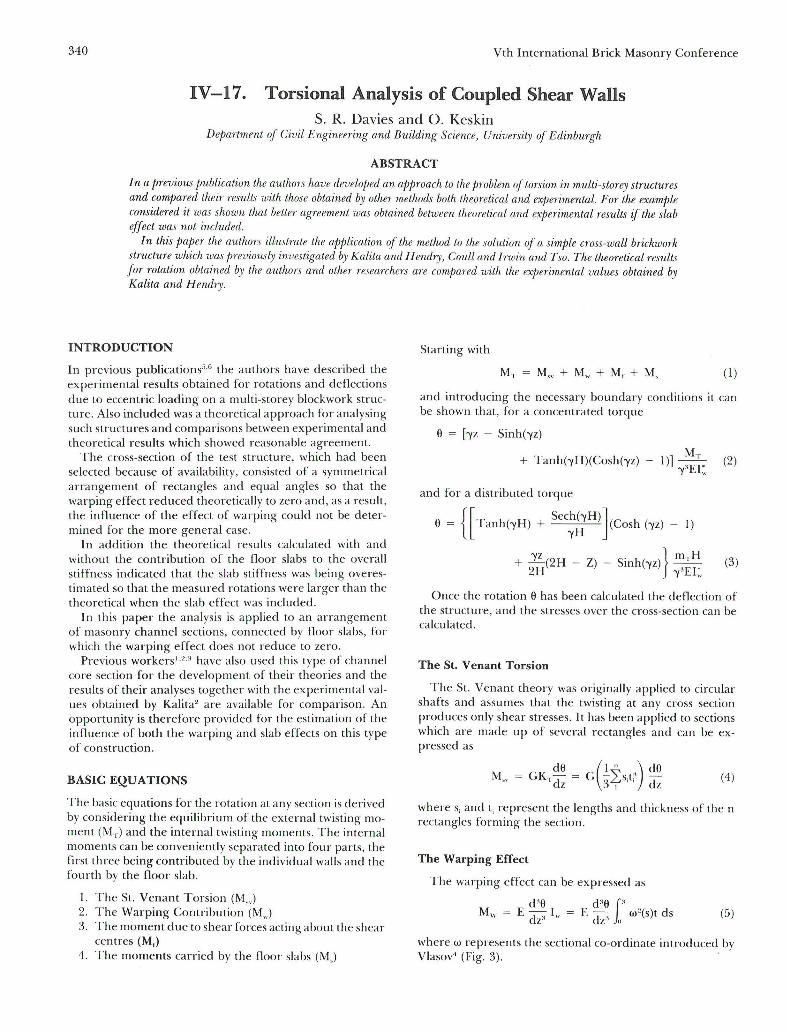
In Fig. 7 the values of the rotation ca1culated with and without the slab effect are compared with the practical results obtained by Kalita and the theoretical results of others. A comparison is also shown in Table I. Although the results obtained when the slab effect is neglected are doser LO lhe practical results than those obtained when the slab influence is induded this is probably caused by the rOlation at the base of the structure. The theory assumes that the base is fully fixed but this condition will not be realized in practice.
341
The important parameter -y which appears in equations 2 and 3 is defined as
Kr /2. 2 + Ks
1* + I" . (9)
The value of 1* is approximately a hundred times larger than Iw so that the neglect of the warping effect is justified but there is no theoretical justification for neglecting K, compared to Kr since the ratio of these terms is not so large. The actual rotation aa due to torsion could be expressed as
(10)
where a is the ca1culated value from equations 2 or 3 and ab is the rotation due to the partial fixity of the base.
It would appear, both for the structure described in this paper and also for the structure reported in Ref. 5 that a" is of a similar magnitude to the part of a due to the slab so that their effects cancel.
The stresses ca1culated from the rotations are shown in Fig. 8 and these compare favourably with those obtained by Kalita2
.
REFERENCES
I. Coull, A. and Irwin , A.W. , Torsional Analysis of Multistorey Shear Wall Struetures, Journal of A.C.!. 1974. 2. Kalita , U.c., Experimental and Theoretical Studies of the S/ruetuml Behaviour of Briekwork Crosswall Sys/ems, Ph.D. Thesis, University af Edinburgh , May 1970. 3. Tso, W.K. and Biswas,J.K. , GenemlAnalysis ofNonplanarCoupled Shear Walls. Journal of lhe Structural Division. A.S .C.E . No:St3 March 1973. 4. Vlasov, V.Z. , Thin-Walled Elastie Beams. Translated from the Russian by the Israel program for Scientific Translalions. Jerusalem , 1961. 5. Keskin, O. and Davies, S.R., The Effeet of Torsion on M ultis/orey Struelures. Inlernational Symposium on Loadbearing Brickwark. London,June 1974. 6. Davies, S.R. and Keskin O ., The Effeet of Eeeentrie Loads OI! Multistorey slmelures, 2nd International Symposium on Bearing Walls , Warsaw, Seplember 1975.
Q* ~1\:V
;-
:.~
.=
Figure 5. Shear forces and tarques fram walls

342
Figure 1. Isometric view of structure
b CSI
+
~
p=r ~2--~ r'-"--- - -- - - - - - -- -- - - + -- -- ---------... _- -_ .. I :
GC, +
~ C'XI
e XI
y
oLx l -\
GC2 +
I I
L. ______ ------------ ... -r--- ..... -.------ -------; M,
Figure 2. Plan of core wall structure
t
CS2 +
~e
Vth International Brick Masonry Conference
U1n LVr
~. ----- -----1 o
........... -.:-. -_. __ ... - ._-_. __ ._._~--..~"'"
Figure 3. Diagram of the sectorial coordinate
ql
, T2
-+~X2 ~1Q~2 QY2
Figure 4. InternaI shear forces and torques fram individ· ual walls due to distributed shear forces
Figure 6. Diagram of the sectorial static moment
Session I V, Paper 17, T orsional Analysis of Coupled Shear Walls
TABLE l-Comparison of theoretical and experimental results, showing the terms of rotation in
cluded in the formulae and the percentage difference. The terms are listed below
, E= 0.98 x 10
Ibf// 1n2
A. COUlL A.W. IRWIN
W.K. TSO
~.
~~o~ot::-c?"A.~
GK,
GK,
GKT
GK,
GKT
GK,
i; ,. ,;; ..,
,o
" EKsc
EKsl
EK"
." <-," S "-0, .<'" , <-
J'0t$ <\ is .t'
E I' Elwc
EI' E1wT
EI ' El wK
Er' ElwK
EI'
E IWK
u. C. KA Ll TA" FROM J. P.. BENJAMIN
U.C. KAlITA'S EXPEP.IMENTA L DATA
Eb't [b- l-tJ[1 . A ] 196 4 I"
AND
EKs, ,
2E [be . b'J À,
AND
ANO
.. E" E"E" E, ; ~26xlO' lo O.l2<IO'J Iblj,n'
ROTATION~ ( P.odx ,81 Pr rcr ntogr Fo' rl i1frffncr EACH STOREY
Irom
1st 2'<J 3'd ~th e"xpf rtme-nlOl
2.2 6.8 11.4 13.6 15 °/0
0 .4 0.9 \.2 1.5 91 °/0
2.0 6.2 lQ3 12.3 2;f'/o
2.4 7.6 13.0 15.5 2°10
2. 4 7.7 13.2 i 5.7 1 °/0
9aO 263. 366. 431-
3.2 6.8 10.1 13 .6 1 S°lo
4 .1 6.6 12.5 15.9
~============~<?P
A A
t
10 15 20
R OTATIO N f Rod x IÕs J
Figure 7. Storey/Rotation curves for structure. Com pariSOI1 of theoretical and expe rimental results from "Kalita"
I, , , , , I I L HH+tttt!:1V
o
+ o o Proposed theory
+ Experimental o Kalita 5' calculation
Figure 8 . Ve rtical stress distribu tion 111 the web at sectio l1 A-A


![Nonlinear nonuniform torsional vibrations of shear ...in [2], a static postbuckling analysis of a framed structure is presented, thus the nonlinear torsional vibration problem is not](https://static.fdocuments.net/doc/165x107/5e27a1eaca2f2a61261e13f2/nonlinear-nonuniform-torsional-vibrations-of-shear-in-2-a-static-postbuckling.jpg)
