Issue L Original Instruction Manual - Lesker
46
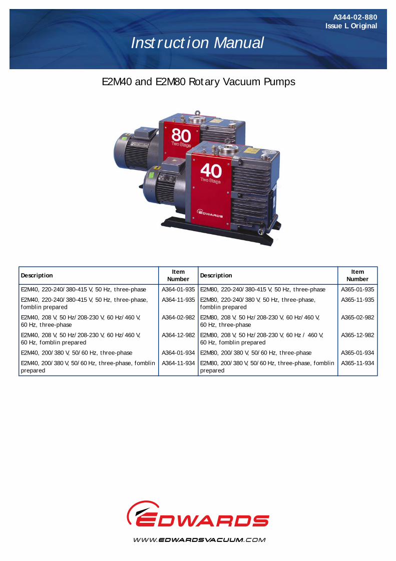
A344-02-880 Issue L Original Instruction Manual E2M40 and E2M80 Rotary Vacuum Pumps Description Item Number Description Item Number E2M40, 220-240/380-415 V, 50 Hz, three-phase A364-01-935 E2M80, 220-240/380-415 V, 50 Hz, three-phase A365-01-935 E2M40, 220-240/380-415 V, 50 Hz, three-phase, fomblin prepared A364-11-935 E2M80, 220-240/380 V, 50 Hz, three-phase, fomblin prepared A365-11-935 E2M40, 208 V, 50 Hz/208-230 V, 60 Hz/460 V, 60 Hz, three-phase A364-02-982 E2M80, 208 V, 50 Hz/208-230 V, 60 Hz/460 V, 60 Hz, three-phase A365-02-982 E2M40, 208 V, 50 Hz/208-230 V, 60 Hz/460 V, 60 Hz, fomblin prepared A364-12-982 E2M80, 208 V, 50 Hz/208-230 V, 60 Hz / 460 V, 60 Hz, fomblin prepared A365-12-982 E2M40, 200/380 V, 50/60 Hz, three-phase A364-01-934 E2M80, 200/380 V, 50/60 Hz, three-phase A365-01-934 E2M40, 200/380 V, 50/60 Hz, three-phase, fomblin prepared A364-11-934 E2M80, 200/380 V, 50/60 Hz, three-phase, fomblin prepared A365-11-934
Transcript of Issue L Original Instruction Manual - Lesker
A344-02-880Issue L Original
Instruction Manual
E2M40 and E2M80 Rotary Vacuum Pumps
DescriptionItem
NumberDescription
Item Number
E2M40, 220-240/380-415 V, 50 Hz, three-phase A364-01-935 E2M80, 220-240/380-415 V, 50 Hz, three-phase A365-01-935
E2M40, 220-240/380-415 V, 50 Hz, three-phase, fomblin prepared
A364-11-935 E2M80, 220-240/380 V, 50 Hz, three-phase, fomblin prepared
A365-11-935
E2M40, 208 V, 50 Hz/208-230 V, 60 Hz/460 V, 60 Hz, three-phase
A364-02-982 E2M80, 208 V, 50 Hz/208-230 V, 60 Hz/460 V, 60 Hz, three-phase
A365-02-982
E2M40, 208 V, 50 Hz/208-230 V, 60 Hz/460 V, 60 Hz, fomblin prepared
A364-12-982 E2M80, 208 V, 50 Hz/208-230 V, 60 Hz / 460 V, 60 Hz, fomblin prepared
A365-12-982
E2M40, 200/380 V, 50/60 Hz, three-phase A364-01-934 E2M80, 200/380 V, 50/60 Hz, three-phase A365-01-934
E2M40, 200/380 V, 50/60 Hz, three-phase, fomblin prepared
A364-11-934 E2M80, 200/380 V, 50/60 Hz, three-phase, fomblin prepared
A365-11-934
This product has been manufactured under a quality system registered to ISO9001
Declaration of Conformity
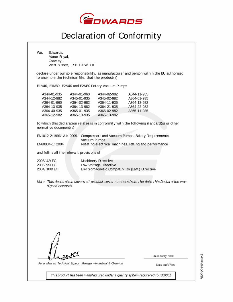
We, Edwards, Manor Royal, Crawley, West Sussex, RH10 9LW, UK declare under our sole responsibility, as manufacturer and person within the EU authorised to assemble the technical file, that the product(s) E1M40, E1M80, E2M40 and E2M80 Rotary Vacuum Pumps
A344-01-935 A344-01-960 A344-02-982 A344-11-935 A344-12-982 A345-01-935 A345-02-982 A364-01-935 A364-01-960 A364-02-982 A364-11-935 A364-12-982 A364-13-935 A364-13-982 A364-21-935 A364-22-982 A364-40-935 A365-01-935 A365-02-982 A365-11-935 A365-12-982 A365-13-935 A365-13-982
to which this declaration relates is in conformity with the following standard(s) or other normative document(s) EN1012-2:1996, A1: 2009 Compressors and Vacuum Pumps. Safety Requirements. Vacuum Pumps EN60034-1: 2004 Rotating electrical machines. Rating and performance and fulfils all the relevant provisions of 2006/42/EC Machinery Directive 2006/95/EC Low Voltage Directive 2004/108/EC Electromagnetic Compatibility (EMC) Directive Note: This declaration covers all product serial numbers from the date this Declaration was
signed onwards.
Peter Meares, Technical Support Manager – Industrial & Chemical Date and Place
P200
-00-
640
Issu
e B 26 January 2010
© Edwards Limited 2011. All rights reserved. Page iEdwards and the Edwards logo are trademarks of Edwards Limited.
Contents
A344-02-880 Issue L
Contents
Section Page
1 Introduction ....................................................................................... 1
1.1 Scope and definitions ................................................................................................... 11.2 Description ................................................................................................................ 21.3 Gas-ballast ................................................................................................................ 3
2 Technical data .................................................................................... 5
2.1 Operating and storage conditions ..................................................................................... 52.2 Performance .............................................................................................................. 52.3 Mechanical data .......................................................................................................... 82.4 Electrical data: three-phase motors .................................................................................. 82.5 Lubrication data ......................................................................................................... 9
3 Installation ....................................................................................... 11
3.1 Safety .....................................................................................................................113.2 System design considerations .........................................................................................113.3 Unpack and inspect .....................................................................................................123.4 Locate the pump ........................................................................................................133.5 Fill the pump with oil ..................................................................................................133.5.1 Recommended pump oils ..............................................................................................133.5.2 Filling procedure ........................................................................................................133.6 Electrical installation: three-phase motors .........................................................................143.6.1 Connect the pump to your electrical supply .......................................................................143.6.2 Check the direction of rotation ......................................................................................143.7 Connect the pump inlet to your system .............................................................................153.7.1 General information ....................................................................................................153.7.2 Connect to ISO40 fittings ..............................................................................................153.7.3 Connect to NW40 fittings ..............................................................................................153.8 Connect the pump outlet to your system ...........................................................................163.9 Gas-ballast inlet connection ..........................................................................................163.10 Leak-test the system ...................................................................................................17
4 Operation ........................................................................................ 19
4.1 Gas-ballast control .....................................................................................................194.2 Start-up procedure .....................................................................................................194.3 To achieve ultimate vacuum ..........................................................................................204.4 To pump condensable vapours ........................................................................................204.5 To decontaminate the oil ..............................................................................................204.6 Unattended operation ..................................................................................................204.7 Shut-down ................................................................................................................21
5 Maintenance ..................................................................................... 23
5.1 Safety .....................................................................................................................235.2 Maintenance plan .......................................................................................................235.3 Check the oil-level .....................................................................................................245.4 Replace the oil ..........................................................................................................245.5 Replace the fine oil-filter .............................................................................................255.6 Replace the gas-ballast filter .........................................................................................265.7 Inspect and clean the inlet-filter .....................................................................................265.8 Clean the oil-level sight-glass .........................................................................................285.9 Clean the motor fan-cover ............................................................................................29
gea/
0145
/02/
11
A344-02-880 Issue L
Page ii © Edwards Limited 2011. All rights reserved.Edwards and the Edwards logo are trademarks of Edwards Limited.
Contents
5.10 Clean and overhaul the pump .........................................................................................295.11 Test the motor condition ..............................................................................................295.12 Fit new blades ...........................................................................................................295.13 Basic fault-finding ......................................................................................................295.13.1 The pump has failed to start ..........................................................................................295.13.2 The pump fails to achieve its specified performance .............................................................295.13.3 The pump is noisy ....................................................................................................... 305.13.4 The pump is too hot ....................................................................................................305.13.5 The vacuum is not fully maintained after the pump is switched off ...........................................305.13.6 The pumping speed is poor ............................................................................................315.13.7 There is an external oil leak ..........................................................................................31
6 Storage and disposal ........................................................................... 33
6.1 Storage ...................................................................................................................336.2 Disposal ...................................................................................................................33
7 Spares and accessories ......................................................................... 35
7.1 Introduction .............................................................................................................357.2 Service ....................................................................................................................357.3 Spares .....................................................................................................................357.4 Accessories ...............................................................................................................367.4.1 Inlet dust-filter ..........................................................................................................367.4.2 Inlet catchpot ...........................................................................................................367.4.3 High-capacity inlet dust-filter ........................................................................................367.4.4 Inlet chemical-trap .....................................................................................................367.4.5 Outlet catchpot .........................................................................................................377.4.6 Outlet mist-filter (clean applications) ..............................................................................377.4.7 Outlet mist-filter (toxic applications) ...............................................................................377.4.8 External oil filter .......................................................................................................377.4.9 Oil-level monitor ........................................................................................................387.4.10 Solenoid-operated gas-ballast control valve .......................................................................387.4.11 Vibration isolators ......................................................................................................38
For return of equipment, complete the HS Forms at the end of this manual.
Illustrations
Figure Page
1 The rotary vacuum pump (E2M40 shown) ............................................................................ 22 Dimensions E2M40 (mm) ................................................................................................ 63 Dimensions E2M80 (mm) ................................................................................................ 74 Connect inlet to ISO40 fittings ........................................................................................155 Connect inlet to NW40 inlet fittings .................................................................................166 Fine oil-filter and gas-ballast bearing-plate locations ............................................................257 Remove and replace inlet-filter ......................................................................................278 Oil-level sight-glass assembly .........................................................................................289 Accessories ...............................................................................................................39
© Edwards Limited 2011. All rights reserved. Page iiiEdwards and the Edwards logo are trademarks of Edwards Limited.
Contents
A344-02-880 Issue L
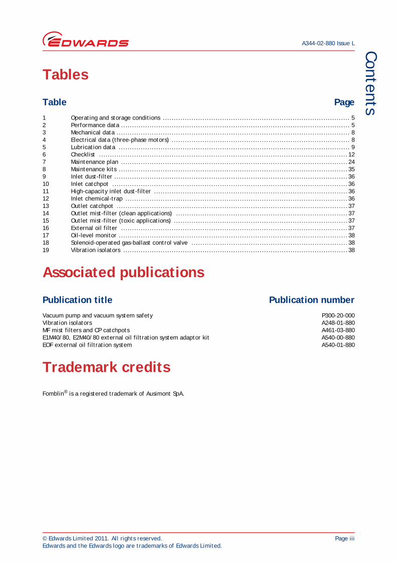
Tables
Table Page
1 Operating and storage conditions ..................................................................................... 52 Performance data ........................................................................................................ 53 Mechanical data .......................................................................................................... 84 Electrical data (three-phase motors) ................................................................................. 85 Lubrication data ......................................................................................................... 96 Checklist .................................................................................................................127 Maintenance plan .......................................................................................................248 Maintenance kits ........................................................................................................359 Inlet dust-filter ..........................................................................................................3610 Inlet catchpot ...........................................................................................................3611 High-capacity inlet dust-filter ........................................................................................3612 Inlet chemical-trap .....................................................................................................3613 Outlet catchpot .........................................................................................................3714 Outlet mist-filter (clean applications) ..............................................................................3715 Outlet mist-filter (toxic applications) ...............................................................................3716 External oil filter .......................................................................................................3717 Oil-level monitor ........................................................................................................3818 Solenoid-operated gas-ballast control valve .......................................................................3819 Vibration isolators ......................................................................................................38
Associated publications
Publication title Publication number
Vacuum pump and vacuum system safety P300-20-000Vibration isolators A248-01-880MF mist filters and CP catchpots A461-03-880E1M40/80, E2M40/80 external oil filtration system adaptor kit A540-00-880EOF external oil filtration system A540-01-880
Trademark credits
Fomblin® is a registered trademark of Ausimont SpA.

This page has been intentionally left blank.
A344-02-880 Issue L
Page iv © Edwards Limited 2011. All rights reserved.Edwards and the Edwards logo are trademarks of Edwards Limited.
© Edwards Limited 2011. All rights reserved. Page 1Edwards and the Edwards logo are trademarks of Edwards Limited.
IntroductionA344-02-880 Issue L
1 Introduction
1.1 Scope and definitions
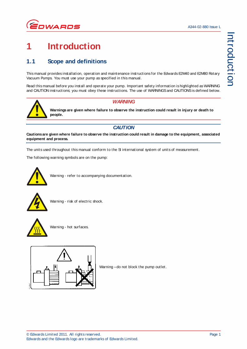
This manual provides installation, operation and maintenance instructions for the Edwards E2M40 and E2M80 Rotary Vacuum Pumps. You must use your pump as specified in this manual.
Read this manual before you install and operate your pump. Important safety information is highlighted as WARNING and CAUTION instructions; you must obey these instructions. The use of WARNINGS and CAUTIONS is defined below.
CAUTIONCautions are given where failure to observe the instruction could result in damage to the equipment, associated equipment and process.
The units used throughout this manual conform to the SI international system of units of measurement.
The following warning symbols are on the pump:
WARNING
Warnings are given where failure to observe the instruction could result in injury or death to people.
Warning - refer to accompanying documentation.
Warning - risk of electric shock.
Warning - hot surfaces.
Warning – do not block the pump outlet.
A344-02-880 Issue L
Page 2 © Edwards Limited 2011. All rights reserved.Edwards and the Edwards logo are trademarks of Edwards Limited.
Introduction
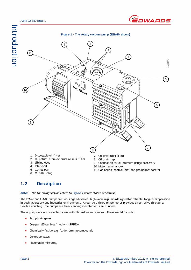
Figure 1 - The rotary vacuum pump (E2M40 shown)
1.2 Description
Note: The following section refers to Figure 1 unless stated otherwise.
The E2M40 and E2M80 pumps are two-stage oil-sealed, high-vacuum pumps designed for reliable, long-term operation in both laboratory and industrial environments. A four-pole three-phase motor provides direct-drive through a flexible coupling. The pumps are free-standing mounted on steel runners.
These pumps are not suitable for use with Hazardous substances. These would include:
Pyrophoric gases.
Oxygen >25% unless filled with PFPE oil.
Chemically Active e.g. Azide forming compounds
Corrosive gases.
Flammable mixtures.
1. Disposable oil-filter2. Oil return, from external oil mist filter3. Lifting-eyes4. Inlet-port5. Outlet-port6. Oil filler-plug
7. Oil-level sight-glass8. Oil drain-tap9. Connection for oil pressure gauge accessory10. Motor terminal-box11. Gas-ballast control inlet and gas-ballast control
© Edwards Limited 2011. All rights reserved. Page 3Edwards and the Edwards logo are trademarks of Edwards Limited.
IntroductionA344-02-880 Issue L
The E2M pumps are two-stage, oil-sealed, sliding-vane vacuum pumps.
Lubrication is provided by a sliding vane oil pump. Oil is drawn into the pump through a wire mesh strainer. The oil is pumped to a spring-loaded distributor valve. The distributor valve directs a lightly-pressurised supply of oil to the main vacuum-pump and by-passes the excess back to the oil reservoir. Some of the excess oil is re-directed through a large area, fine-pore filter and some through a relief-valve. When you switch off an E2M40 or E2M80 pump with the gas ballast control closed, the spring loaded distributor valve provides oil and air suckback protection.
You can inspect the level and condition of oil in the oil box through an oil-level sight-glass (7). An oil filler-plug (6) is fitted at the top of the oil box. An oil drain-tap (8) is fitted at the bottom of the oil box.
The inlet-port flange (4) is compatible with ISO40 or NW40 fittings. The outlet-port (5) has an NW25 flange.
The gas-ballast control (11) allows you to control the introduction of gas-ballast when pumping high vapour loads. Refer to Section 1.3 for more information about gas-ballast.
Refer to Section 7 for details about vibration isolators and other recommended accessories.
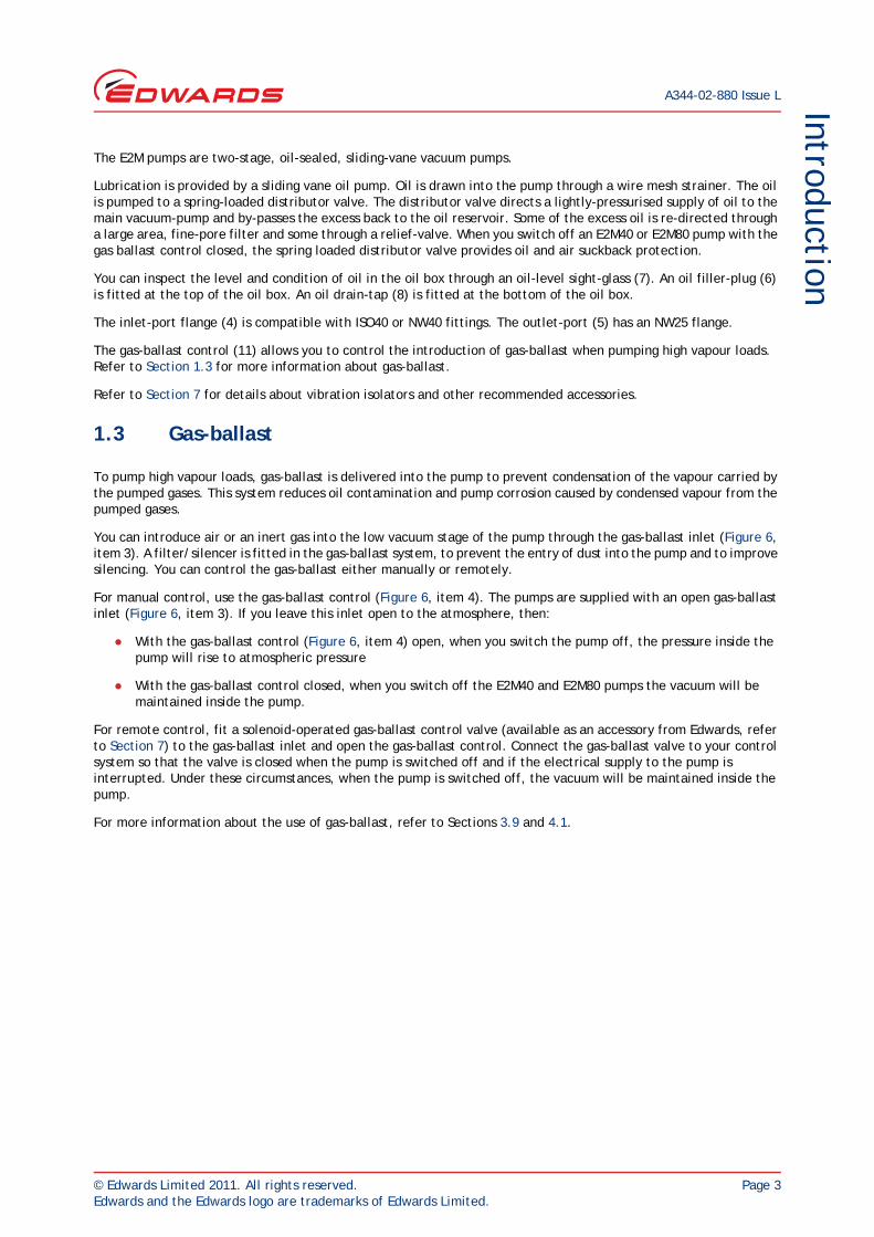
1.3 Gas-ballast
To pump high vapour loads, gas-ballast is delivered into the pump to prevent condensation of the vapour carried by the pumped gases. This system reduces oil contamination and pump corrosion caused by condensed vapour from the pumped gases.
You can introduce air or an inert gas into the low vacuum stage of the pump through the gas-ballast inlet (Figure 6, item 3). A filter/silencer is fitted in the gas-ballast system, to prevent the entry of dust into the pump and to improve silencing. You can control the gas-ballast either manually or remotely.
For manual control, use the gas-ballast control (Figure 6, item 4). The pumps are supplied with an open gas-ballast inlet (Figure 6, item 3). If you leave this inlet open to the atmosphere, then:
With the gas-ballast control (Figure 6, item 4) open, when you switch the pump off, the pressure inside the pump will rise to atmospheric pressure
With the gas-ballast control closed, when you switch off the E2M40 and E2M80 pumps the vacuum will be maintained inside the pump.
For remote control, fit a solenoid-operated gas-ballast control valve (available as an accessory from Edwards, refer to Section 7) to the gas-ballast inlet and open the gas-ballast control. Connect the gas-ballast valve to your control system so that the valve is closed when the pump is switched off and if the electrical supply to the pump is interrupted. Under these circumstances, when the pump is switched off, the vacuum will be maintained inside the pump.
For more information about the use of gas-ballast, refer to Sections 3.9 and 4.1.

A344-02-880 Issue L
Page 4 © Edwards Limited 2011. All rights reserved.Edwards and the Edwards logo are trademarks of Edwards Limited.
This page has been intentionally left blank.
© Edwards Limited 2011. All rights reserved. Page 5Edwards and the Edwards logo are trademarks of Edwards Limited.
Technical data
A344-02-880 Issue L
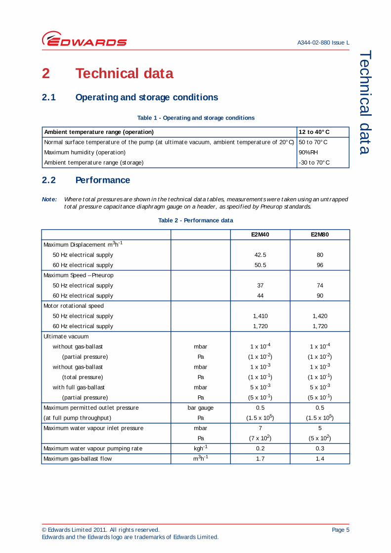
2 Technical data
2.1 Operating and storage conditions
2.2 Performance
Note: Where total pressures are shown in the technical data tables, measurements were taken using an untrapped total pressure capacitance diaphragm gauge on a header, as specified by Pneurop standards.
Table 1 - Operating and storage conditions
Ambient temperature range (operation) 12 to 40°C
Normal surface temperature of the pump (at ultimate vacuum, ambient temperature of 20°C) 50 to 70°C
Maximum humidity (operation) 90% RH
Ambient temperature range (storage) -30 to 70°C
Table 2 - Performance data
E2M40 E2M80
Maximum Displacement m3h-1
50 Hz electrical supply 42.5 80
60 Hz electrical supply 50.5 96
Maximum Speed – Pneurop
50 Hz electrical supply 37 74
60 Hz electrical supply 44 90
Motor rotational speed
50 Hz electrical supply 1,410 1,420
60 Hz electrical supply 1,720 1,720
Ultimate vacuum
without gas-ballast mbar 1 x 10⁻⁴ 1 x 10⁻⁴
(partial pressure) Pa (1 x 10⁻²) (1 x 10⁻²)
without gas-ballast mbar 1 x 10⁻³ 1 x 10⁻³
(total pressure) Pa (1 x 10⁻¹) (1 x 10⁻¹)
with full gas-ballast mbar 5 x 10⁻³ 5 x 10⁻³
(partial pressure) Pa (5 x 10⁻¹) (5 x 10⁻¹)
Maximum permitted outlet pressure bar gauge 0.5 0.5
(at full pump throughput) Pa (1.5 x 10⁵) (1.5 x 10⁵)
Maximum water vapour inlet pressure mbar 7 5
Pa (7 x 10²) (5 x 10²)
Maximum water vapour pumping rate kgh-1 0.2 0.3
Maximum gas-ballast flow m3h-1 1.7 1.4
A344-02-880 Issue L
Page 6 © Edwards Limited 2011. All rights reserved.Edwards and the Edwards logo are trademarks of Edwards Limited.
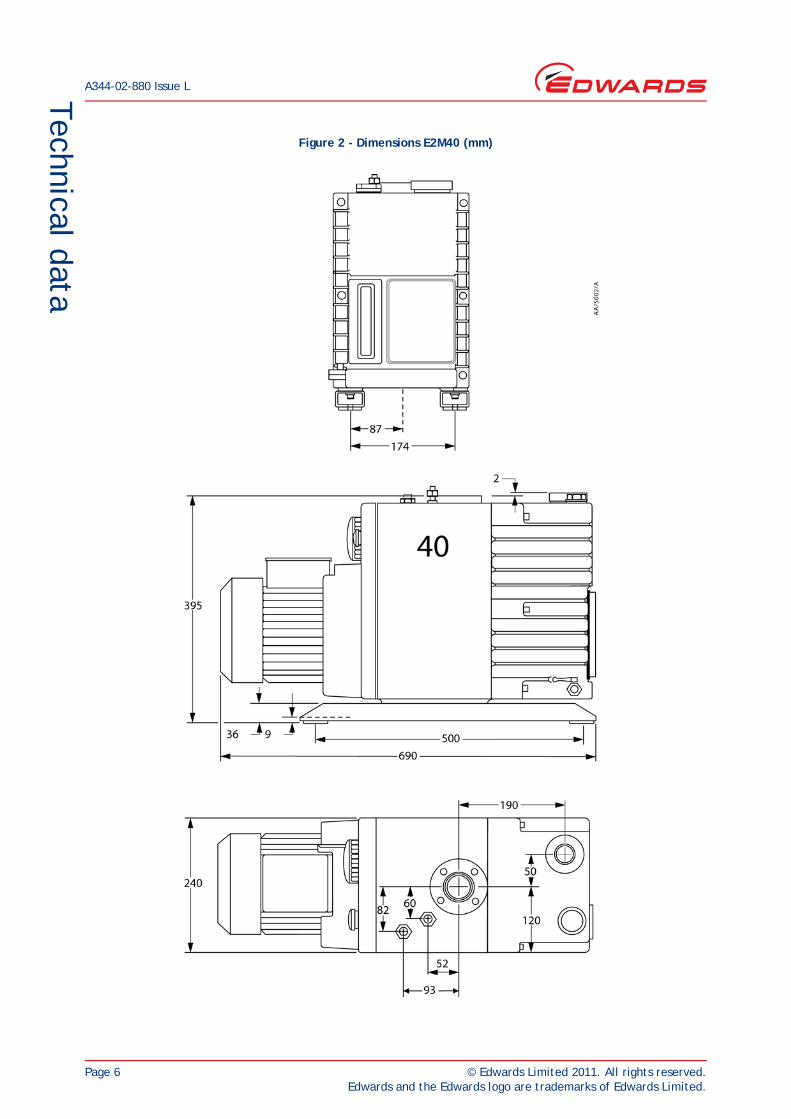
Technical data
Figure 2 - Dimensions E2M40 (mm)
© Edwards Limited 2011. All rights reserved. Page 7Edwards and the Edwards logo are trademarks of Edwards Limited.
Technical data
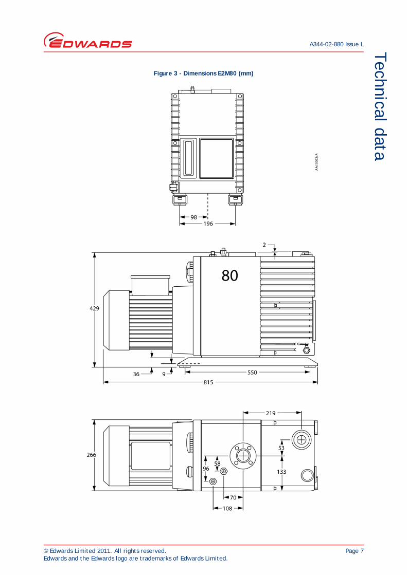
A344-02-880 Issue L
Figure 3 - Dimensions E2M80 (mm)
A344-02-880 Issue L
Page 8 © Edwards Limited 2011. All rights reserved.Edwards and the Edwards logo are trademarks of Edwards Limited.
Technical data
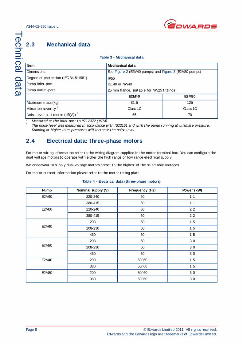
2.3 Mechanical data
† Measured at the inlet port to ISO 2372 (1974)* The noise level was measured in accordance with ISO2151 and with the pump running at ultimate pressure.
Running at higher inlet pressures will increase the noise level.
2.4 Electrical data: three-phase motors
For motor wiring information refer to the wiring diagram supplied in the motor terminal box. You can configure the dual voltage motors to operate with either the high range or low range electrical supply.
We endeavour to supply dual voltage motors preset to the highest of the selectable voltages.
For motor current information please refer to the motor rating plate.
Table 3 - Mechanical data
Item Mechanical data
Dimensions See Figure 2 (E2M40 pumps) and Figure 3 (E2M80 pumps)
IP55
ISO40 or NW40
25 mm flange, suitable for NW25 fittings
Degree of protection (IEC 34-5:1981)
Pump inlet-port
Pump outlet-port
E2M40 E2M80
Maximum mass (kg) 81.5 125
Vibration severity † Class 1C Class 1C
Noise level at 1 metre (dB(A)) * 65 70
Table 4 - Electrical data (three-phase motors)
Pump Nominal supply (V) Frequency (Hz) Power (kW)
E2M40 220-240 50 1.1
380-415 50 1.1
E2M80 220-240 50 2.2
380-415 50 2.2
E2M40208 50 1.5
208-230 60 1.5
460 60 1.5
E2M80208 50 3.0
208-230 60 3.0
460 60 3.0
E2M40 200 50/60 1.5
380 50/60 1.5
E2M80 200 50/60 3.0
380 50/60 3.0
© Edwards Limited 2011. All rights reserved. Page 9Edwards and the Edwards logo are trademarks of Edwards Limited.
Technical data
A344-02-880 Issue L
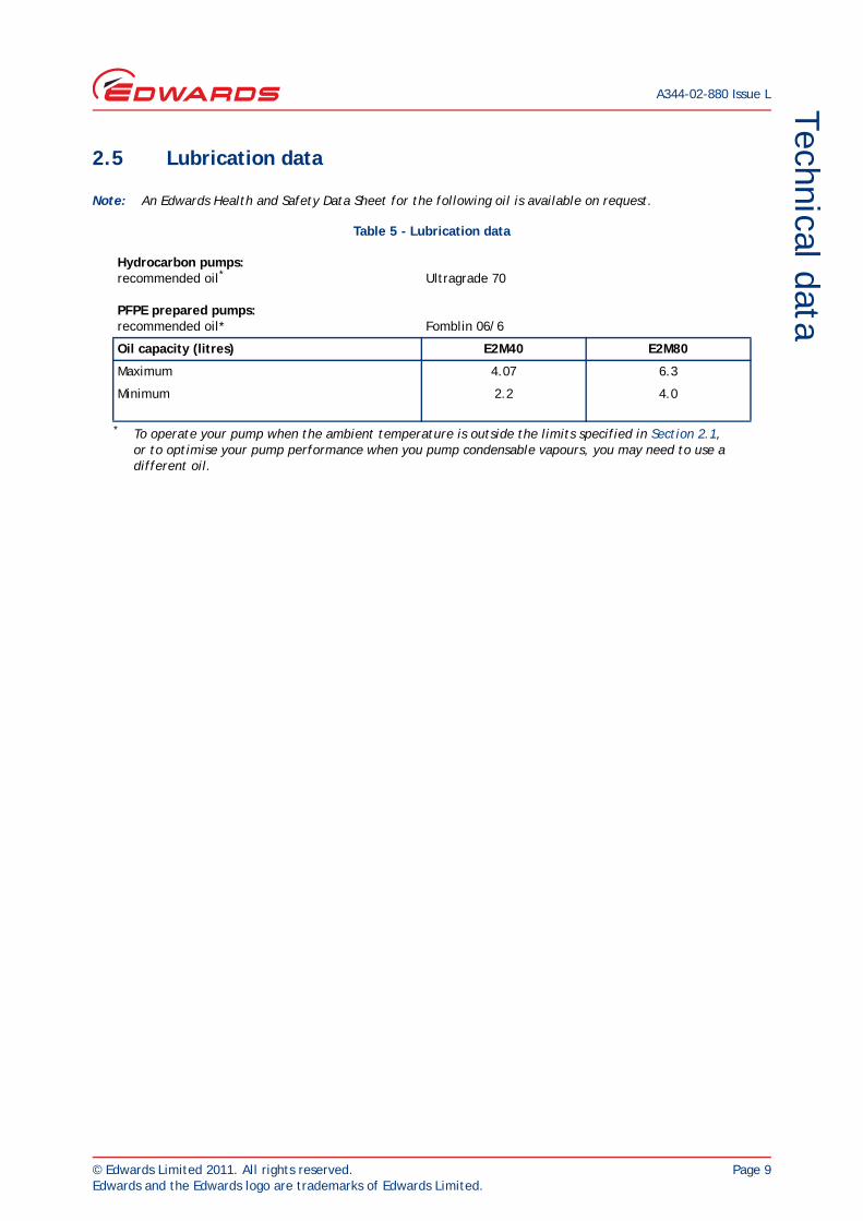
2.5 Lubrication data
Note: An Edwards Health and Safety Data Sheet for the following oil is available on request.
Table 5 - Lubrication data
Hydrocarbon pumps:recommended oil*
PFPE prepared pumps:recommended oil*
* To operate your pump when the ambient temperature is outside the limits specified in Section 2.1, or to optimise your pump performance when you pump condensable vapours, you may need to use a different oil.
Ultragrade 70
Fomblin 06/6
Oil capacity (litres) E2M40 E2M80
Maximum 4.07 6.3
Minimum 2.2 4.0

A344-02-880 Issue L
Page 10 © Edwards Limited 2011. All rights reserved.Edwards and the Edwards logo are trademarks of Edwards Limited.
This page has been intentionally left blank.
© Edwards Limited 2011. All rights reserved. Page 11Edwards and the Edwards logo are trademarks of Edwards Limited.
InstallationA344-02-880 Issue L
3 Installation
3.1 Safety
You must ensure that the pump is suitable for your application. If you have any doubt about the suitability of the pump for your application, refer to the Edwards guidelines on vacuum pump and vacuum system safety. (See Associated Publications at the end of the contents list).
Obey the safety instructions listed below when you install the pump, especially when you connect the pump into an existing system. Details of specific safety precautions are given at the appropriate point in the instructions.
The installation of your pump must be performed by a suitably trained and supervised technician
Wear the appropriate safety-clothing when you come into contact with contaminated components
Vent and purge your vacuum system before you start installation work
Ensure that the installation technician is familiar with the safety procedures which relate to the pump-oil and the products handled by the pumping system. Take suitable precautions to avoid the inhalation of oil mist and excessive skin contact with pump-oil, as prolonged exposure can be harmful
Disconnect the other components in the pumping system from the electrical supply so that they cannot be operated accidentally.
3.2 System design considerations
Consider the following points when you design your pumping system:
Use a suitable valve to isolate the pump from your vacuum system if you need to allow the pump to warm up before you pump condensable vapours or if you need to maintain vacuum when the pump is switched off
Avoid high levels of heat input to the pump from the process gases, otherwise the pump may overheat and seize
If you use the pump in a high ambient temperature and have a high gas throughput, the temperature of the pump-body may exceed 70°C. You must fit suitable guards to prevent contact with hot surfaces
Make sure that the exhaust pipeline cannot become blocked. If you have an exhaust-isolation valve, make sure that you cannot operate the pump with the valve closed
Provide for a purge of inert gas when you shut down the pumping system, to dilute dangerous gases to safe concentrations. A suitable solenoid operated gas-ballast control valve for introduction of purge-gas into the pump is available as an accessory (see Section 7).
WARNING
Obey the safety instructions given below and take note of appropriate precautions. If you do not, you may cause injury to people and damage to equipment.
A344-02-880 Issue L
Page 12 © Edwards Limited 2011. All rights reserved.Edwards and the Edwards logo are trademarks of Edwards Limited.
Installation
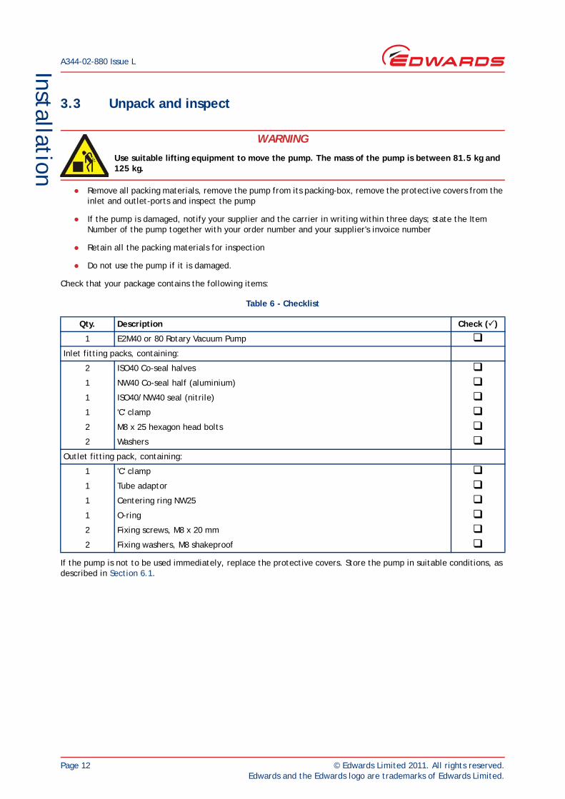
3.3 Unpack and inspect
Remove all packing materials, remove the pump from its packing-box, remove the protective covers from the inlet and outlet-ports and inspect the pump
If the pump is damaged, notify your supplier and the carrier in writing within three days; state the Item Number of the pump together with your order number and your supplier's invoice number
Retain all the packing materials for inspection
Do not use the pump if it is damaged.
Check that your package contains the following items:
If the pump is not to be used immediately, replace the protective covers. Store the pump in suitable conditions, as described in Section 6.1.
WARNING
Use suitable lifting equipment to move the pump. The mass of the pump is between 81.5 kg and 125 kg.
Table 6 - Checklist
Qty. Description Check ()
1 E2M40 or 80 Rotary Vacuum Pump Inlet fitting packs, containing:
2 ISO40 Co-seal halves 1 NW40 Co-seal half (aluminium) 1 ISO40/NW40 seal (nitrile) 1 'C' clamp 2 M8 x 25 hexagon head bolts 2 Washers
Outlet fitting pack, containing:
1 'C' clamp 1 Tube adaptor 1 Centering ring NW25 1 O-ring 2 Fixing screws, M8 x 20 mm 2 Fixing washers, M8 shakeproof
© Edwards Limited 2011. All rights reserved. Page 13Edwards and the Edwards logo are trademarks of Edwards Limited.
InstallationA344-02-880 Issue L
3.4 Locate the pump
Attach your mechanical lifting equipment to the lifting eyes on the pump.
Provide a firm, level platform for the pump. Locate the pump so that the oil-level sight-glass is visible and the oil filler-plug, oil drain-tap, disposable oil-filter and gas-ballast control are accessible.
If your pump will be located inside an enclosure, make sure that there is adequate ventilation at both ends of the pump, so that the ambient temperature around the pump does not exceed 40°C. There must be a minimum space of 25 mm between the pump and the enclosure walls.
In addition, ensure that the location of the pump and the intended routing of connecting parts i.e. process line, exhaust line and power cables will not present any physical hazards. For example: trip hazards to personnel.
3.5 Fill the pump with oil
3.5.1 Recommended pump oils
When the ambient temperature is 12°C or higher, we recommend that you use Edwards Ultragrade 70 oil. This tested and proven oil will give you the best performance, maintenance intervals and pump life. Otherwise, use another oil with the specification VG ISO 68.
If you pump oxygen or other dangerous gases and vapours, you must use a chemically inert and stable oil (such as perfluoropolyether). For information on pumping dangerous gases and vapours, refer to the Edwards guidelines on vacuum pump and vacuum system safety (see Associated Publications at the end of the contents list).
3.5.2 Filling procedure
Fill the pump with oil as described below. Refer to Figure 1 for the item numbers in brackets.
1. Remove the oil filler-plug (6).
2. Pour oil into the pump until the oil-level just reaches the MAX mark on the bezel at the top of the sight-glass (7). If the oil-level goes above the MAX mark, open the oil drain-tap (8) and drain the excess oil from the pump. When the oil-level falls to the MAX mark close the oil drain-tap (8).
3. After a few minutes, recheck the oil-level. If the oil-level is now below the MAX mark, pour more oil into the pump.
4. Refit the oil filler-plug (6). Tighten the plug firmly by hand. Do not over-tighten.
WARNING
Use suitable lifting equipment to move the pump. The mass of the pump is between 81.5 kg and 125 kg.
WARNING
If you use a hyrdocarbon oil in this pump, you must not use the pump to process oxygen in concentrations greater than 25% in volume. If you do, there is a risk of fire or explosion in the oil-box of the pump.
A344-02-880 Issue L
Page 14 © Edwards Limited 2011. All rights reserved.Edwards and the Edwards logo are trademarks of Edwards Limited.
Installation
3.6 Electrical installation: three-phase motors
3.6.1 Connect the pump to your electrical supply
CAUTIONIf your pump-motor can be used with more than one voltage range, you must ensure that the motor is configured for your electrical supply voltage. If you do not, you may damage the motor.
Note: The pump will restart automatically when the electrical supply is restored after an interruption. If you do not want the pump to restart automatically, use electrical control equipment which must be reset manually.
We recommend that you connect the electrical supply to the motor through a starter or circuit breaker which has thermal over-current protection which can be adjusted to suit the full-load current ratings shown on the motor rating plate. The fuse ratings must be calculated by a qualified electrician. The supplier of your thermal over-current protection device may specify fuse ratings to ensure correct operation of the over-current protection device. Ensure that the fuse you use is suitable for the starting currents given on the motor rating plate.
1. Remove the cover from the motor terminal box.
2. Check your electrical supply voltage and frequency. If necessary, configure the motor to operate with your electrical supply. For motor wiring information refer to the wiring diagram supplied in the motor terminal box.
3. Remove the 20 mm diameter plugs from the cable-entry hole that you will use for the electrical supply cable. Choose the most suitable hole for your application.
4. Fit a suitable cable-gland and nut to the entry hole. After the supply cable is fitted, the cable-gland must be a protective seal to the standard of IP44 in IEC 529 or better.
5. Pass the motor electrical supply cable through the cable-gland.
6. Connect the cables to the terminals as shown in the wiring diagram supplied in the motor terminal box.
3.6.2 Check the direction of rotation
CAUTIONEnsure that the pump-motor rotates in the correct direction. If it does not, the pump and your vacuum system can become pressurised.
1. Watch the motor cooling-fan through the motor fan-cover.
2. Switch-on the electrical supply to the motor for a few seconds and switch off.
3. Check that the motor cooling-fan rotates in the direction shown by the arrow on the motor mounting-plate. If the direction of rotation is incorrect:
Isolate the pump from the electrical supply
Remove the terminal-box cover and swap wires L1 and L3. Refer to the wiring diagram supplied in the motor terminal box
Refit the cover to the terminal-box
Connect the pump to the electrical supply
Check the direction of rotation again.
WARNING
Ensure that the electrical installation of your pump-motor conforms with your local and national safety requirements. It must be connected to a suitably fused and protected electrical supply and a suitable earth point.
© Edwards Limited 2011. All rights reserved. Page 15Edwards and the Edwards logo are trademarks of Edwards Limited.
InstallationA344-02-880 Issue L
3.7 Connect the pump inlet to your system
3.7.1 General information
Take note of the following information when you connect the pump to your vacuum system Refer to Section 7 for details of the accessories mentioned below.
For optimum pumping speeds, ensure that the pipeline connected to the inlet-port is as short as possible and has an internal diameter not less than the inlet-port diameter
Support the vacuum pipelines to prevent loading of the coupling-joints
If necessary, incorporate flexible bellows in your system pipelines to reduce the transmission of vibration and to prevent loading of coupling-joints. If you use flexible bellows, you must ensure that you use bellows which have a maximum pressure rating which is greater than the highest pressure that can be generated in your system. You must use flexible bellows if your pump is mounted on vibration isolators. We recommend that you use Edwards flexible bellows
Use a suitable valve to isolate the pump from your vacuum system if you need to pump condensable vapours or maintain vacuum when the pump is switched off
Use a suitable inlet catchpot if you pump condensable vapours or if you use the pump for very dusty applications
Ensure that sealing surfaces are clean and scratch-free.
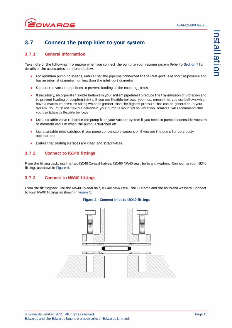
3.7.2 Connect to ISO40 fittings
From the fitting pack, use the two ISO40 Co-seal halves, ISO40/NW40 seal, bolts and washers. Connect to your ISO40 fittings as shown in Figure 4.
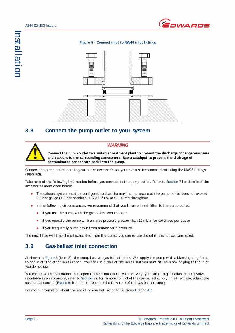
3.7.3 Connect to NW40 fittings
From the fitting pack, use the NW40 Co-seal half, ISO40/NW40 seal, the 'C' clamp and the bolts and washers. Connect to your NW40 fittings as shown in Figure 5.
Figure 4 - Connect inlet to ISO40 fittings
A344-02-880 Issue L
Page 16 © Edwards Limited 2011. All rights reserved.Edwards and the Edwards logo are trademarks of Edwards Limited.
Installation
Figure 5 - Connect inlet to NW40 inlet fittings
3.8 Connect the pump outlet to your system
Connect the pump outlet-port to your outlet accessories or your exhaust treatment plant using the NW25 fittings (supplied).
Take note of the following information before you connect to the pump outlet. Refer to Section 7 for details of the accessories mentioned below.
The exhaust system must be configured so that the maximum pressure at the pump outlet does not exceed 0.5 bar gauge (1.5 bar absolute, 1.5 x 10⁵ Pa) at full pump throughput.
In the following circumstances, we recommend that you fit an oil mist filter to the pump outlet:
if you use the pump with the gas-ballast control open
if you operate the pump with an inlet pressure greater than 10 mbar for extended periods or
if you frequently pump down from atmospheric pressure.
The mist filter will trap the oil exhausted from the pump: you can re-use the oil if it is not contaminated.
3.9 Gas-ballast inlet connection
As shown in Figure 6 (item 3), the pump has two gas-ballast inlets. We supply the pump with a blanking plug fitted to one inlet: the other inlet is open. You can use either of the inlets, but you must fit the blanking plug to the inlet you do not use.
You can leave the gas-ballast inlet open to the atmosphere. Alternatively, you can fit a gas-ballast control valve, (available as an accessory, refer to Section 7), for remote control of the gas-ballast supply. In either case, adjust the gas-ballast control (Figure 6, item 4), to regulate the flow rate of the gas-ballast supply.
For more information about the use of gas-ballast, refer to Sections 1.3 and 4.1.
WARNING
Connect the pump outlet to a suitable treatment plant to prevent the discharge of dangerous gases and vapours to the surrounding atmosphere. Use a catchpot to prevent the drainage of contaminated condensate back into the pump.
© Edwards Limited 2011. All rights reserved. Page 17Edwards and the Edwards logo are trademarks of Edwards Limited.
InstallationA344-02-880 Issue L
3.10 Leak-test the system
Leak-test the system and seal any leaks found after you have installed the pump, to prevent leakage of substances out of the system and leakage of air into the system.

A344-02-880 Issue L
Page 18 © Edwards Limited 2011. All rights reserved.Edwards and the Edwards logo are trademarks of Edwards Limited.
This page has been intentionally left blank.
© Edwards Limited 2011. All rights reserved. Page 19Edwards and the Edwards logo are trademarks of Edwards Limited.
Operation
A344-02-880 Issue L
4 Operation
4.1 Gas-ballast control
Use the gas-ballast control (Figure 1, item 11) to change the amount of air (or inert gas) introduced into the low-vacuum stage of the pump. Use of the gas-ballast will prevent the condensation of vapours in the pump. The condensed vapours would contaminate the oil.
Turn the gas-ballast control fully clockwise:
to achieve ultimate vacuum
to pump dry gases.
Turn the gas-ballast control anti-clockwise to open. Use the gas-ballast control fully open:
to pump high concentrations of condensable vapour
to decontaminate the oil.
When you operate the pump with the gas-ballast control open, there is an increased rate of oil loss from the pump.
4.2 Start-up procedure
If the oil is contaminated, or if the pump temperature is below 13°C, or if the supply voltage is more than 10% below the lowest voltage specified for the motor, the pump may operate at reduced speed for a few minutes.
1. Switch on the electrical supply to the pump.
2. Check that the oil-level in the sight-glass drops slightly (3 to 5 mm) after start-up. This shows that the pump has primed with oil.
3. If the pump fails to prime, operate the pump with the inlet open to atmosphere for approximately 30 seconds. Then isolate the inlet and check that the oil-level drops 3-5 mm.
4. If you want to achieve ultimate vacuum, to pump condensable vapours or to decontaminate the pump oil, refer to the procedures in Sections 4.3, 4.4 and 4.5 respectively. Otherwise, open the vacuum system isolation-valve.
WARNING
We do not recommend that you use the E2M40 and E2M80 pumps to pump hazardous substances.
WARNING
Do not block the pump outlet or allow the outlet pressure to rise above 1.5 bar absolute. If you do, the oil box may fracture: this may cause injury to people.
A344-02-880 Issue L
Page 20 © Edwards Limited 2011. All rights reserved.Edwards and the Edwards logo are trademarks of Edwards Limited.
Operation
4.3 To achieve ultimate vacuum
If the pump does not achieve the performance specified in Section 2, make sure that this is not due to your system design before you contact your supplier or Edwards for advice. In particular, the vapour pressure of all materials used in your vacuum system, including pump oil, must be much lower than the specified ultimate vacuum of the pump. Refer to Section 5.13.2 for a list of possible causes for failure to achieve the specified performance. The most common causes are:
Your pressure measurement technique or gauge head is unsuitable or the gauge head is faulty
You have used an oil other than the recommended oil, and the vapour pressure of the oil is higher than the specified ultimate vacuum of the pump.
Use the following procedure to achieve ultimate vacuum:
1. Isolate the pump from your vacuum system.
2. Turn the gas-ballast control (Figure 6, item 4) fully anti-clockwise (fully open) and operate the pump for at least 1 hour (or overnight) to thoroughly purge the oil of contaminants.
3. Close the gas-ballast control (Figure 6, item 4).
4. Open the vacuum system isolation-valve and pump down to ultimate vacuum.
4.4 To pump condensable vapours
Use gas-ballast when there is a high proportion of condensable vapours in the process gases.
1. Close the vacuum system isolation valve.
2. Turn the gas-ballast control (Figure 6, item 4) anti-clockwise to fully open and operate the pump for 30 minutes to warm the oil. This will help to prevent vapour condensation in the pump.
3. Open the vacuum system isolation-valve and continue to operate the pump with the gas-ballast control open.
After you have pumped condensable vapours, you can (if necessary) decontaminate the oil. Use the procedure in Section 4.5.
4.5 To decontaminate the oil
The oil in the pump should be clear. If the oil is cloudy or discoloured it is contaminated with process vapours.
1. Look at the condition of the oil in the sight-glass (Figure 1, item 7). If the oil is cloudy or discoloured, continue with the procedure at Step 2 below.
2. Close the vacuum system isolation-valve.
3. Turn the gas-ballast control (Figure 6, item 4) fully anti-clockwise.
4. Operate the pump until the oil is clear.
4.6 Unattended operation
The pump is designed for unattended operation under the normal operating conditions specified in Section 2. However, we recommend that you check the pump at a regular interval of not more than 14 days. Check the pump more frequently if you pump high volumes of gas or if you operate the pump with the gas-ballast control (Figure 6, item 4) open.
© Edwards Limited 2011. All rights reserved. Page 21Edwards and the Edwards logo are trademarks of Edwards Limited.
Operation
A344-02-880 Issue L
4.7 Shut-down
Note: If the gas-ballast control is open and the pump is switched off for any reason, the pump drive shaft may rotate in the reverse direction, causing a system pressure rise. To prevent this, use a gas-ballast control valve (refer to Section 7.4.10).
We recommend, as described in the procedure below, that you decontaminate the oil before you shut down the pump. Decontamination of the oil will prevent damage to the pump by the contaminants in the oil.
1. Refer to Section 4.5 and decontaminate the oil, as required.
2. Close the vacuum system isolation-valve (if not already closed).
3. Turn gas-ballast control (Figure 6, item 4) clockwise to close.
4. Switch off the electrical supply to the pump.

A344-02-880 Issue L
Page 22 © Edwards Limited 2011. All rights reserved.Edwards and the Edwards logo are trademarks of Edwards Limited.
This page has been intentionally left blank.
© Edwards Limited 2011. All rights reserved. Page 23Edwards and the Edwards logo are trademarks of Edwards Limited.
Maintenance
A344-02-880 Issue L
5 Maintenance
5.1 Safety
Ensure that maintenance is done by a suitably trained and supervised technician. Obey your local and national safety requirements
Ensure that the maintenance technician is familiar with the safety procedures which relate to the pump-oil and the products processed by the pumping system
Check that all the required parts are available and of the correct type before you start work
Isolate the pump and other components from the electrical supply so that they cannot be operated accidentally
Allow the pump to cool to a safe temperature before you start maintenance work
Do not re-use O-rings and seals if they are damaged
After maintenance is completed, recheck the direction of pump rotation if the electrical supply has been disconnected
Do not touch or inhale the thermal breakdown products of fluorinated materials which may be present if the pump has been heated to 310°C and above. Fluorinated materials are safe in normal use but can decompose into very dangerous substances (which may include hydrofluoric acid) if they are heated to 310°C and above. The pump may have overheated if it was misused or if it was in a fire. Health and Safety Data sheets for fluorinated materials used in the pump are available on request; contact your supplier or Edwards
Leak-test the system after maintenance work is complete if you have connected or disconnected any vacuum or exhaust joints; seal any leaks found
The pump and the pump-oil will be contaminated with the process chemicals that have been pumped during operation. Ensure that the pump is decontaminated before maintenance and that you take adequate precautions to protect people from the effects of dangerous substances if contamination has occurred.
5.2 Maintenance plan
The plan shown in Table 7 details the routine maintenance operations necessary to maintain your pump in normal use. Instructions for each operation are given in the section shown.
More frequent maintenance may be required if you use your pump with gas-ballast or to pump corrosive or abrasive gases and vapours. If necessary, adjust the maintenance plan according to your experience.
When you maintain the pump, use Edwards spares and maintenance kits; these contain all of the components necessary to complete maintenance operations successfully. The Item Numbers of the spares and kits are given in Section 7.
Examine the condition of any external accessories, filters or traps (if fitted). Refer to the instructions supplied with these accessories for maintenance procedures.
WARNING
Obey the safety instructions given below and take note of appropriate precautions. If you do not, you can cause injury to people and damage to equipment.
A344-02-880 Issue L
Page 24 © Edwards Limited 2011. All rights reserved.Edwards and the Edwards logo are trademarks of Edwards Limited.
Maintenance
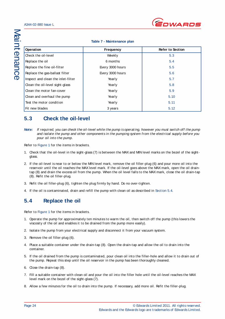
5.3 Check the oil-level
Note: If required, you can check the oil-level while the pump is operating, however you must switch off the pump and isolate the pump and other components in the pumping system from the electrical supply before you pour oil into the pump.
Refer to Figure 1 for the items in brackets.
1. Check that the oil-level in the sight-glass (7) is between the MAX and MIN level marks on the bezel of the sight-glass.
2. If the oil-level is near to or below the MIN level mark, remove the oil filler-plug (6) and pour more oil into the reservoir until the oil reaches the MAX level mark. If the oil-level goes above the MAX mark, open the oil drain-tap (8) and drain the excess oil from the pump. When the oil level falls to the MAX mark, close the oil drain-tap (8). Refit the oil filler-plug.
3. Refit the oil filler-plug (6), tighten the plug firmly by hand. Do no over-tighten.
4. If the oil is contaminated, drain and refill the pump with clean oil as described in Section 5.4.
5.4 Replace the oil
Refer to Figure 1 for the items in brackets.
1. Operate the pump for approximately ten minutes to warm the oil, then switch off the pump (this lowers the viscosity of the oil and enables it to be drained from the pump more easily).
2. Isolate the pump from your electrical supply and disconnect it from your vacuum system.
3. Remove the oil filler-plug (6).
4. Place a suitable container under the drain-tap (8). Open the drain-tap and allow the oil to drain into the container.
5. If the oil drained from the pump is contaminated, pour clean oil into the filler-hole and allow it to drain out of the pump. Repeat this step until the oil reservoir in the pump has been thoroughly cleaned.
6. Close the drain-tap (8).
7. Fill a suitable container with clean oil and pour the oil into the filler hole until the oil-level reaches the MAX level mark on the bezel of the sight-glass (7).
8. Allow a few minutes for the oil to drain into the pump. If necessary, add more oil. Refit the filler-plug.
Table 7 - Maintenance plan
Operation Frequency Refer to Section
Check the oil-level Weekly 5.3
Replace the oil 6 months 5.4
Replace the fine oil-filter Every 3000 hours 5.5
Replace the gas-ballast filter Every 3000 hours 5.6
Inspect and clean the inlet-filter Yearly 5.7
Clean the oil-level sight-glass Yearly 5.8
Clean the motor fan-cover Yearly 5.9
Clean and overhaul the pump Yearly 5.10
Test the motor condition Yearly 5.11
Fit new blades 3 years 5.12
© Edwards Limited 2011. All rights reserved. Page 25Edwards and the Edwards logo are trademarks of Edwards Limited.
Maintenance
A344-02-880 Issue L
9. Replace the fine oil-filter (see Section 5.5).
10. Replace the gas-ballast filter (see Section 5.6).
11. Reconnect the pump to your vacuum system.
12. Reconnect the electrical supply to your pump.
5.5 Replace the fine oil-filter
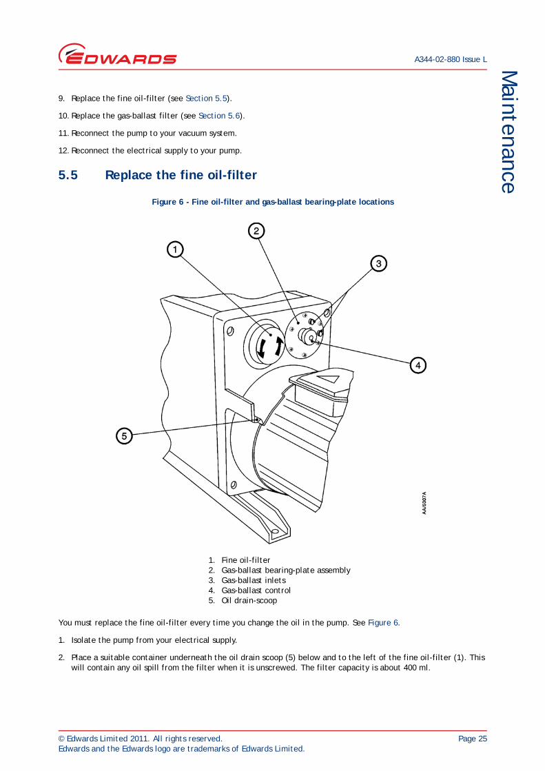
Figure 6 - Fine oil-filter and gas-ballast bearing-plate locations
You must replace the fine oil-filter every time you change the oil in the pump. See Figure 6.
1. Isolate the pump from your electrical supply.
2. Place a suitable container underneath the oil drain scoop (5) below and to the left of the fine oil-filter (1). This will contain any oil spill from the filter when it is unscrewed. The filter capacity is about 400 ml.
1. Fine oil-filter2. Gas-ballast bearing-plate assembly3. Gas-ballast inlets4. Gas-ballast control5. Oil drain-scoop
A344-02-880 Issue L
Page 26 © Edwards Limited 2011. All rights reserved.Edwards and the Edwards logo are trademarks of Edwards Limited.
Maintenance
3. Unscrew the filter (direction arrows shown in Figure 6) using a suitable strap-wrench. Clean off any oil-spillage on pump and filter housing surfaces. Dispose of the filter and any oil-spillage according to local environment regulations covering industrial waste.
4. Make sure that the filter sealing ring (supplied with the new filter) is seated correctly on the new filter. Screw in the new filter and tighten 1/4 turn using the strap-wrench.
5.6 Replace the gas-ballast filter
You must replace the gas-ballast filter elements every time you change the oil in the pump (see Figure 6).
1. Isolate the pump from your electrical supply.
2. Unscrew and remove the M6 x 16 mm long socket-head screws securing the gas-ballast bearing-plate (2).
3. Note the orientation of the bearing-plate before removing it so that you can replace it correctly later.
4. Remove the bearing-plate containing the two filter elements from the valve body.
5. Slide the two filter elements off the bearing-plate and discard them.
6. Clean the bearing-plate assembly before fitting new filter elements by washing it in a suitable cleansing solution. Allow the assembly to dry.
7. Fit two new filter elements to the bearing-plate.
8. Replace the assembly into the valve body in the correct orientation and secure with the two screws removed earlier.
9. Reconnect the electrical supply to your pump.
5.7 Inspect and clean the inlet-filter
You must remove and clean the inlet-filter (positioned in the inlet-port) every time you change the oil in the pump (see Figure 7).
© Edwards Limited 2011. All rights reserved. Page 27Edwards and the Edwards logo are trademarks of Edwards Limited.
Maintenance
A344-02-880 Issue L
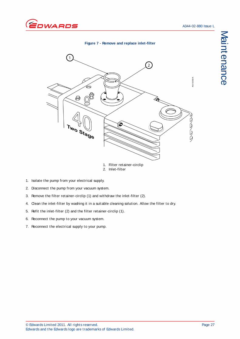
Figure 7 - Remove and replace inlet-filter
1. Isolate the pump from your electrical supply.
2. Disconnect the pump from your vacuum system.
3. Remove the filter retainer-circlip (1) and withdraw the inlet-filter (2).
4. Clean the inlet-filter by washing it in a suitable cleaning solution. Allow the filter to dry.
5. Refit the inlet-filter (2) and the filter retainer-circlip (1).
6. Reconnect the pump to your vacuum system.
7. Reconnect the electrical supply to your pump.
1. Filter retainer-circlip2. Inlet-filter
A344-02-880 Issue L
Page 28 © Edwards Limited 2011. All rights reserved.Edwards and the Edwards logo are trademarks of Edwards Limited.
Maintenance
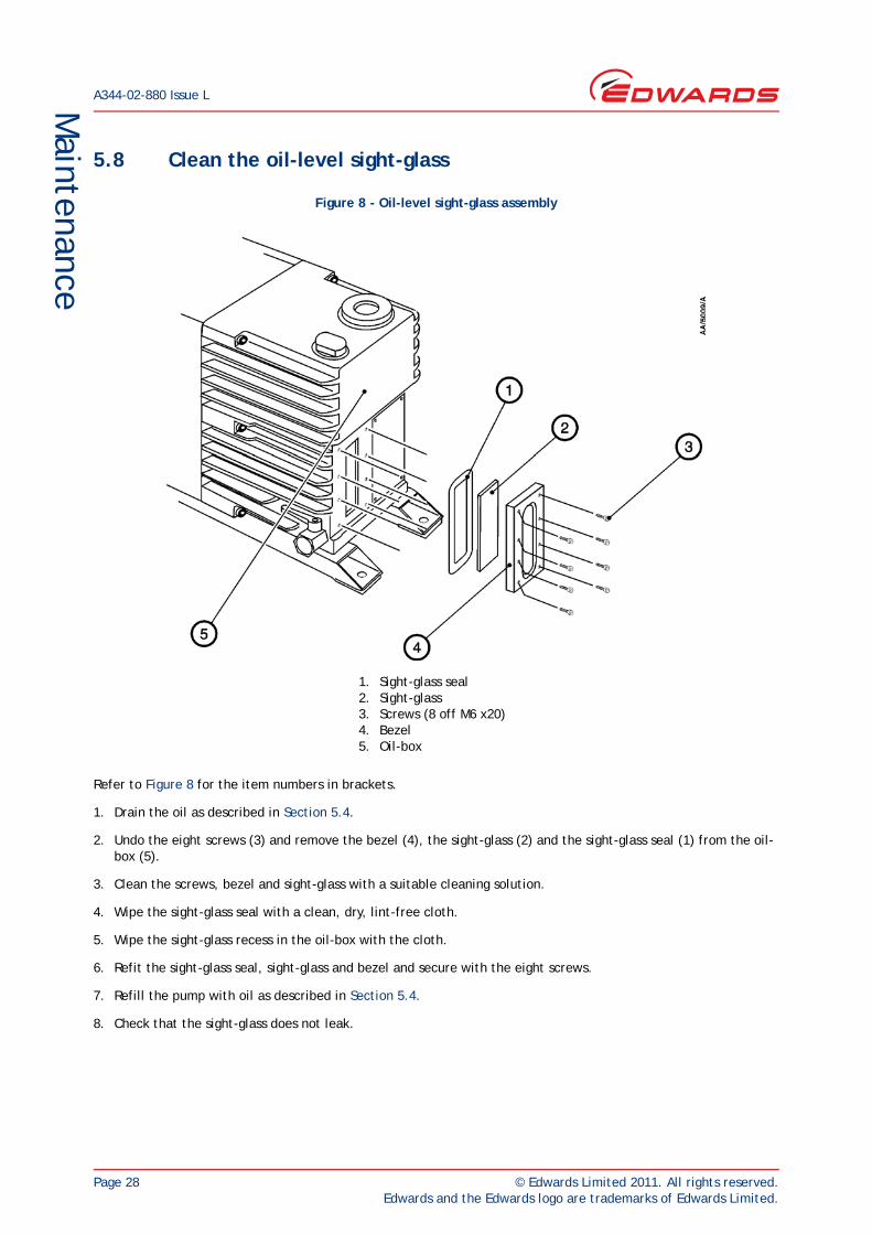
5.8 Clean the oil-level sight-glass
Figure 8 - Oil-level sight-glass assembly
Refer to Figure 8 for the item numbers in brackets.
1. Drain the oil as described in Section 5.4.
2. Undo the eight screws (3) and remove the bezel (4), the sight-glass (2) and the sight-glass seal (1) from the oil-box (5).
3. Clean the screws, bezel and sight-glass with a suitable cleaning solution.
4. Wipe the sight-glass seal with a clean, dry, lint-free cloth.
5. Wipe the sight-glass recess in the oil-box with the cloth.
6. Refit the sight-glass seal, sight-glass and bezel and secure with the eight screws.
7. Refill the pump with oil as described in Section 5.4.
8. Check that the sight-glass does not leak.
1. Sight-glass seal2. Sight-glass3. Screws (8 off M6 x20)4. Bezel5. Oil-box
© Edwards Limited 2011. All rights reserved. Page 29Edwards and the Edwards logo are trademarks of Edwards Limited.
Maintenance
A344-02-880 Issue L
5.9 Clean the motor fan-cover
You must keep the motor fan-cover clean. Your pump may overheat if the air-flow over the motor is restricted.
1. Isolate the pump from your electrical supply.
2. Use a dry cloth and a brush to remove dirt and deposits from the fan-cover.
3. Reconnect the electrical supply to your pump.
5.10 Clean and overhaul the pump
Clean and overhaul the pump as described in the instructions supplied with the clean and overhaul kit (see Section 7).
5.11 Test the motor condition
Test the earth continuity and the insulation resistance of the pump-motor, in accordance with local regulations for periodic testing of electrical equipment. We recommend that the earth continuity is less than 0.1 Ω and the insulation resistance is greater than 10 MΩ. If the motor fails these tests, you must replace the motor.
5.12 Fit new blades
Fit new blades to the pump as described in the instructions supplied with the blade kit (see Section 7).
5.13 Basic fault-finding
A list of fault conditions and their possible causes is provided here to assist you in fault-finding. If you are unable to rectify a fault when you use this guide, call your nearest Edwards Service Centre for help.
5.13.1 The pump has failed to start
The electrical supply fuse is blown
The electrical supply voltage does not match the motor
The outlet pipeline or the outlet-filter (if fitted) is blocked
The oil temperature is below 12°C
The oil is too viscous
The oil is contaminated
The pump has seized after long storage
The pump has been left to stand after contaminants have been pumped and has seized
The motor is faulty.
5.13.2 The pump fails to achieve its specified performance
(Failure to reach ultimate vacuum).
The measuring technique or gauge is unsuitable
You have filled the pump with the wrong type of oil
A344-02-880 Issue L
Page 30 © Edwards Limited 2011. All rights reserved.Edwards and the Edwards logo are trademarks of Edwards Limited.
Maintenance
There is a leak in your vacuum system
The gas-ballast control is set incorrectly
The oil-level is low
The oil is contaminated
Your vacuum fittings are dirty or damaged
The inlet-filter is blocked
The pump has not warmed up
The pump has failed to prime
Motor is rotating in the wrong direction.
5.13.3 The pump is noisy
The motor fan-cover is damaged
The motor bearings are worn
The oil is contaminated with solid particles
The motor coupling is loose
A blade is sticking.
5.13.4 The pump is too hot
The ambient temperature is too high
The cooling-air supply is insufficient or is too hot
The electrical supply voltage is too high
The outlet-filter or the outlet pipeline is blocked
The oil-level is too low
You have filled the pump with the wrong type of oil
The oil is contaminated
The process gas is too hot or the throughput is too high.
5.13.5 The vacuum is not fully maintained after the pump is switched off
The gas-ballast control is open
Damaged or missing O-ring
Anti-suckback valve faulty
Shaft seals damaged
Exhaust valve damaged.
© Edwards Limited 2011. All rights reserved. Page 31Edwards and the Edwards logo are trademarks of Edwards Limited.
Maintenance
A344-02-880 Issue L
5.13.6 The pumping speed is poor
The connecting pipelines are too small in diameter
The connecting pipelines are too long
The inlet-filter is blocked.
5.13.7 There is an external oil leak
The oil-pump shaft-seal is worn or damaged
The oil-box gaskets have deteriorated
There is an oil leak from the gas-ballast control
There is an oil leak from the drain-tap
There is an oil leak from the sight-glass
There is an oil-leak from the fine oil-filter element-seal.

A344-02-880 Issue L
Page 32 © Edwards Limited 2011. All rights reserved.Edwards and the Edwards logo are trademarks of Edwards Limited.
This page has been intentionally left blank.
© Edwards Limited 2011. All rights reserved. Page 33Edwards and the Edwards logo are trademarks of Edwards Limited.
Storage and disposalA344-02-880 Issue L
6 Storage and disposal
6.1 Storage
CAUTIONObserve the storage temperature limits stated in Section 2. Storage below -30°C will permanently damage the pump seals.
Note: If you will store a new pump in conditions of high humidity, remove the pump from its cardboard packaging box; dispose of the box (refer to Section 6.2).
Use the following procedure to store the pump:
1. Ensure that the pump has been shut-down as described in Section 4.
2. Isolate the pump from the electrical supply.
3. Purge your vacuum system and the pump with dry nitrogen and disconnect the pump from your vacuum system.
4. Replace the oil as described in Section 5.4, paragraphs 3 to 8.
5. Place and secure protective covers over the inlet and outlet-ports.
6. Store the pump in cool, dry conditions until required for use.
7. When required, prepare and install the pump as described in Section 3. If the pump has been stored for more than a year, before you install the pump you must clean and overhaul it as described in the instruction supplied with the clean and overhaul kit.
6.2 Disposal
Dispose of the pump, cleaning solutions, deposits removed from the pump, used pump oil, coolant, grease and any components safely in accordance with all local and national safety and environmental requirements.
Particular care must be taken with the following:
Fluoroelastomers which may have decomposed as a result of being subject to high temperatures.
Components and oil which have been contaminated with dangerous process substances.

A344-02-880 Issue L
Page 34 © Edwards Limited 2011. All rights reserved.Edwards and the Edwards logo are trademarks of Edwards Limited.
This page has been intentionally left blank.
© Edwards Limited 2011. All rights reserved. Page 35Edwards and the Edwards logo are trademarks of Edwards Limited.
Spares and accessoriesA344-02-880 Issue L
7 Spares and accessories
7.1 Introduction
Edwards products, spares and accessories are available from Edwards companies in Belgium, Brazil, Canada, France, Germany, Hong Kong, Italy, Japan, Korea, Singapore, Switzerland, United Kingdom, U.S.A, and a world-wide network of distributors. The majority of these centres employ Service Engineers who have undergone comprehensive Edwards training courses.
Order spare parts and accessories from your nearest Edwards company or distributor. When ordering, please state for each part required:
Model and Item Number of your equipment
Serial number (if any)
Item Number and description of part.
7.2 Service
Edwards products are supported by a worldwide network of Edwards Service Centres. Each Service Centre offers a wide range of options including: equipment decontamination; service exchange; repair; rebuild and testing to factory specifications. Equipment which has been serviced, repaired or rebuilt is returned with a full warranty.
Your local Service Centre can also provide Edwards engineers to support on-site maintenance, service or repair of your equipment.
For more information about service options, contact your nearest Centre or other Edwards company.
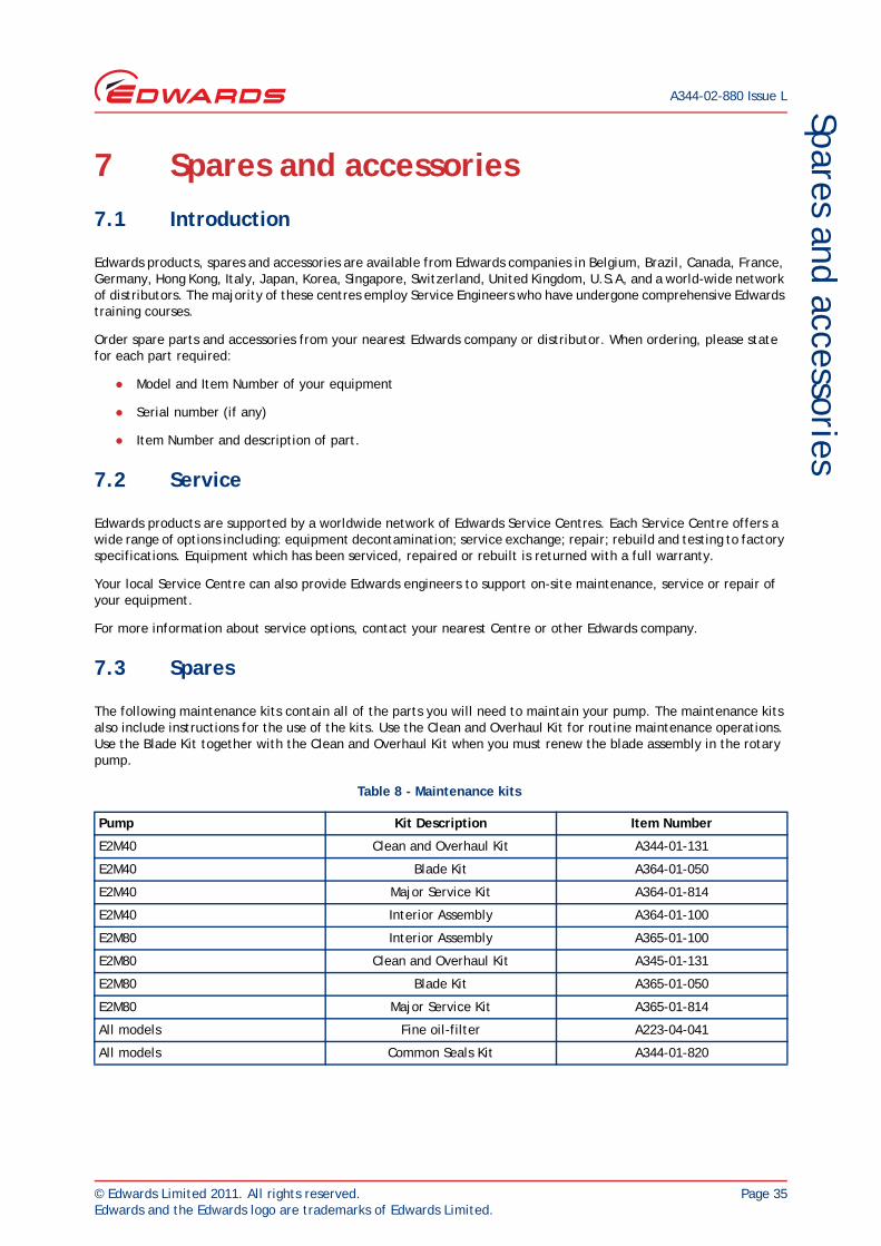
7.3 Spares
The following maintenance kits contain all of the parts you will need to maintain your pump. The maintenance kits also include instructions for the use of the kits. Use the Clean and Overhaul Kit for routine maintenance operations. Use the Blade Kit together with the Clean and Overhaul Kit when you must renew the blade assembly in the rotary pump.
Table 8 - Maintenance kits
Pump Kit Description Item Number
E2M40 Clean and Overhaul Kit A344-01-131
E2M40 Blade Kit A364-01-050
E2M40 Major Service Kit A364-01-814
E2M40 Interior Assembly A364-01-100
E2M80 Interior Assembly A365-01-100
E2M80 Clean and Overhaul Kit A345-01-131
E2M80 Blade Kit A365-01-050
E2M80 Major Service Kit A365-01-814
All models Fine oil-filter A223-04-041
All models Common Seals Kit A344-01-820
A344-02-880 Issue L
Page 36 © Edwards Limited 2011. All rights reserved.Edwards and the Edwards logo are trademarks of Edwards Limited.
Spares and accessories
7.4 Accessories
A range of accessories is available for the E2M40 and E2M80 pumps.
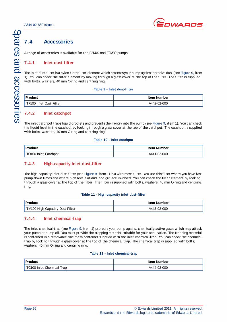
7.4.1 Inlet dust-filter
The inlet dust-filter is a nylon-fibre filter-element which protects your pump against abrasive dust (see Figure 9, item 1). You can check the filter element by looking through a glass cover at the top of the filter. The filter is supplied with bolts, washers, 40 mm O-ring and centring ring.
7.4.2 Inlet catchpot
The inlet catchpot traps liquid droplets and prevents their entry into the pump (see Figure 9, item 1). You can check the liquid level in the catchpot by looking through a glass cover at the top of the catchpot. The catchpot is supplied with bolts, washers, 40 mm O-ring and centring ring.
7.4.3 High-capacity inlet dust-filter
The high-capacity inlet dust-filter (see Figure 9, item 1) is a wire mesh filter. You use this filter where you have fast pump down times and where high levels of dust and grit are involved. You can check the filter element by looking through a glass cover at the top of the filter. The filter is supplied with bolts, washers, 40 mm O-ring and centring ring.
7.4.4 Inlet chemical-trap
The inlet chemical-trap (see Figure 9, item 1) protects your pump against chemically active gases which may attack your pump or pump oil. You must provide the trapping material suitable for your application. The trapping material is contained in a removable fine mesh container supplied with the inlet chemical-trap. You can check the chemical-trap by looking through a glass cover at the top of the chemical trap. The chemical trap is supplied with bolts, washers, 40 mm O-ring and centring ring.
Table 9 - Inlet dust-filter
Product Item Number
ITF100 Inlet Dust Filter A442-02-000
Table 10 - Inlet catchpot
Product Item Number
ITO100 Inlet Catchpot A441-02-000
Table 11 - High-capacity inlet dust-filter
Product Item Number
ITM100 High Capacity Dust Filter A443-02-000
Table 12 - Inlet chemical-trap
Product Item Number
ITC100 Inlet Chemical Trap A444-02-000
© Edwards Limited 2011. All rights reserved. Page 37Edwards and the Edwards logo are trademarks of Edwards Limited.
Spares and accessoriesA344-02-880 Issue L
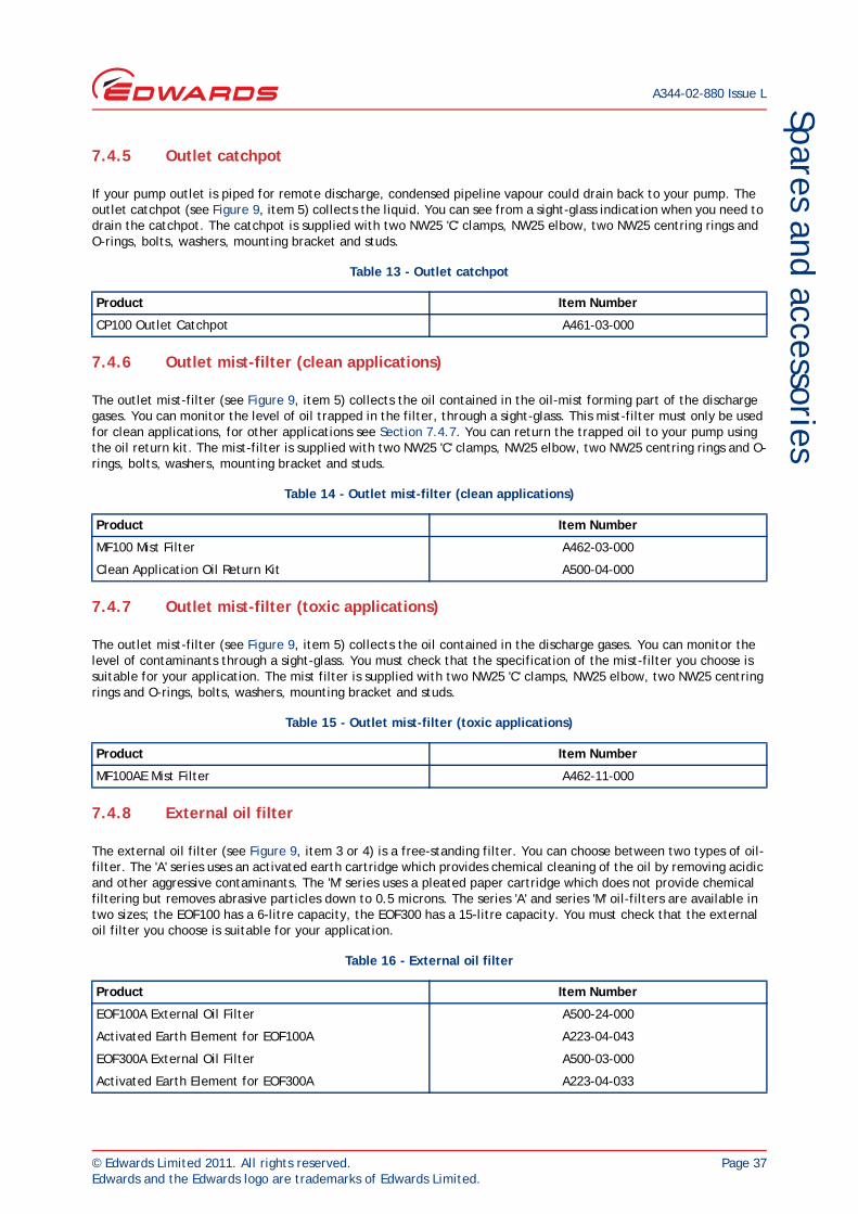
7.4.5 Outlet catchpot
If your pump outlet is piped for remote discharge, condensed pipeline vapour could drain back to your pump. The outlet catchpot (see Figure 9, item 5) collects the liquid. You can see from a sight-glass indication when you need to drain the catchpot. The catchpot is supplied with two NW25 'C' clamps, NW25 elbow, two NW25 centring rings and O-rings, bolts, washers, mounting bracket and studs.
7.4.6 Outlet mist-filter (clean applications)
The outlet mist-filter (see Figure 9, item 5) collects the oil contained in the oil-mist forming part of the discharge gases. You can monitor the level of oil trapped in the filter, through a sight-glass. This mist-filter must only be used for clean applications, for other applications see Section 7.4.7. You can return the trapped oil to your pump using the oil return kit. The mist-filter is supplied with two NW25 'C' clamps, NW25 elbow, two NW25 centring rings and O-rings, bolts, washers, mounting bracket and studs.
7.4.7 Outlet mist-filter (toxic applications)
The outlet mist-filter (see Figure 9, item 5) collects the oil contained in the discharge gases. You can monitor the level of contaminants through a sight-glass. You must check that the specification of the mist-filter you choose is suitable for your application. The mist filter is supplied with two NW25 'C' clamps, NW25 elbow, two NW25 centring rings and O-rings, bolts, washers, mounting bracket and studs.
7.4.8 External oil filter
The external oil filter (see Figure 9, item 3 or 4) is a free-standing filter. You can choose between two types of oil-filter. The 'A' series uses an activated earth cartridge which provides chemical cleaning of the oil by removing acidic and other aggressive contaminants. The 'M' series uses a pleated paper cartridge which does not provide chemical filtering but removes abrasive particles down to 0.5 microns. The series 'A' and series 'M' oil-filters are available in two sizes; the EOF100 has a 6-litre capacity, the EOF300 has a 15-litre capacity. You must check that the external oil filter you choose is suitable for your application.
Table 13 - Outlet catchpot
Product Item Number
CP100 Outlet Catchpot A461-03-000
Table 14 - Outlet mist-filter (clean applications)
Product Item Number
MF100 Mist Filter A462-03-000
Clean Application Oil Return Kit A500-04-000
Table 15 - Outlet mist-filter (toxic applications)
Product Item Number
MF100AE Mist Filter A462-11-000
Table 16 - External oil filter
Product Item Number
EOF100A External Oil Filter A500-24-000
Activated Earth Element for EOF100A A223-04-043
EOF300A External Oil Filter A500-03-000
Activated Earth Element for EOF300A A223-04-033
A344-02-880 Issue L
Page 38 © Edwards Limited 2011. All rights reserved.Edwards and the Edwards logo are trademarks of Edwards Limited.
Spares and accessories
7.4.9 Oil-level monitor
The oil-level monitor (see Figure 9, item 7) fits in place of the existing oil-level sight-glass and bezel. The monitor provides a switching facility which you can use to activate an alarm or other device. You still have the normal visual indication of the oil-level.
7.4.10 Solenoid-operated gas-ballast control valve
The solenoid-operated gas-ballast control valve (see Figure 9, item 2) gives you automatic or remote control of gas-ballast. You can connect the valve to shut off gas-ballast when the pump is switched off and so prevent air from returning to the system.
7.4.11 Vibration isolators
Use vibration isolators (see Figure 9, item 6) to reduce vibration and noise when the pump is floor or frame-mounted. You must use flexible bellows or other flexible piping between inlet and outlet connections when you fit vibration isolators.
EOF100M External Oil Filter A500-25-000
Mechanical Filter Element for EOF100M A223-04-044
EOF300M External Oil Filter A500-23-000
Mechanical Filter Element for EOF300M A223-04-042
EOF100A and M Connection Kit A500-39-000
EOF300A and M Connection Kit A364-01-020
Table 17 - Oil-level monitor
Product Item Number
OLM100 Oil Level Monitor A504-33-000
Table 18 - Solenoid-operated gas-ballast control valve
Product Item Number
EBV300D Solenoid-Operated Gas-BallastA500-17-930
Control Valve for E2M40 and E2M80
Table 19 - Vibration isolators
Product Item Number
Vibration Isolators (set of 4) A248-01-405
Table 16 - External oil filter
Product Item Number
© Edwards Limited 2011. All rights reserved. Page 39Edwards and the Edwards logo are trademarks of Edwards Limited.
Spares and accessoriesA344-02-880 Issue L
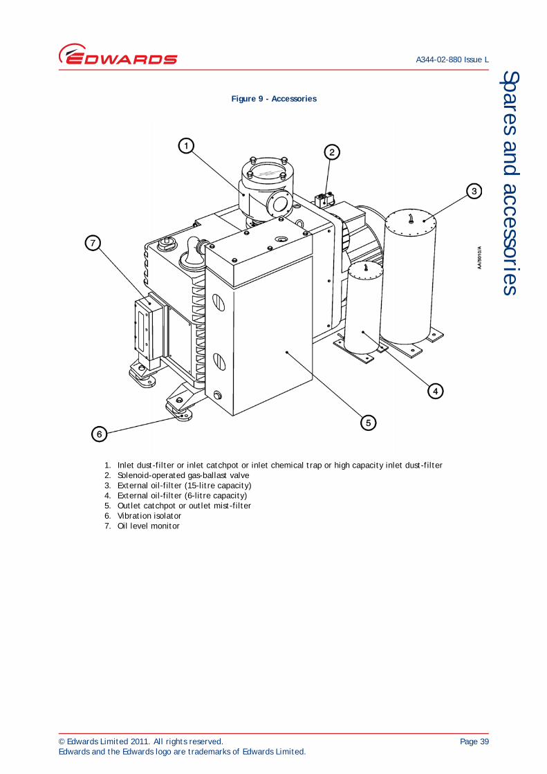
Figure 9 - Accessories
1. Inlet dust-filter or inlet catchpot or inlet chemical trap or high capacity inlet dust-filter2. Solenoid-operated gas-ballast valve3. External oil-filter (15-litre capacity)4. External oil-filter (6-litre capacity)5. Outlet catchpot or outlet mist-filter6. Vibration isolator7. Oil level monitor

A344-02-880 Issue L
Page 40 © Edwards Limited 2011. All rights reserved.Edwards and the Edwards logo are trademarks of Edwards Limited.
This page has been intentionally left blank.