ISS Solar Array Alpha Rotary Joint (SARJ) Bearing Failure ...
25
Christopher DellaCorte and Timothy L. Krantz Glenn Research Center, Cleveland, Ohio Michael J. Dube Goddard Space Flight Center, Greenbelt, Maryland ISS Solar Array Alpha Rotary Joint (SARJ) Bearing Failure and Recovery: Technical and Project Management Lessons Learned NASA/TP—2011-217116 August 2011
Transcript of ISS Solar Array Alpha Rotary Joint (SARJ) Bearing Failure ...

Christopher DellaCorte and Timothy L. KrantzGlenn Research Center, Cleveland, Ohio
Michael J. DubeGoddard Space Flight Center, Greenbelt, Maryland
ISS Solar Array Alpha Rotary Joint (SARJ)Bearing Failure and Recovery: Technical andProject Management Lessons Learned
NASA/TP—2011-217116
August 2011

NASA STI Program . . . in Profi le
Since its founding, NASA has been dedicated to the advancement of aeronautics and space science. The NASA Scientifi c and Technical Information (STI) program plays a key part in helping NASA maintain this important role.
The NASA STI Program operates under the auspices of the Agency Chief Information Offi cer. It collects, organizes, provides for archiving, and disseminates NASA’s STI. The NASA STI program provides access to the NASA Aeronautics and Space Database and its public interface, the NASA Technical Reports Server, thus providing one of the largest collections of aeronautical and space science STI in the world. Results are published in both non-NASA channels and by NASA in the NASA STI Report Series, which includes the following report types: • TECHNICAL PUBLICATION. Reports of
completed research or a major signifi cant phase of research that present the results of NASA programs and include extensive data or theoretical analysis. Includes compilations of signifi cant scientifi c and technical data and information deemed to be of continuing reference value. NASA counterpart of peer-reviewed formal professional papers but has less stringent limitations on manuscript length and extent of graphic presentations.
• TECHNICAL MEMORANDUM. Scientifi c
and technical fi ndings that are preliminary or of specialized interest, e.g., quick release reports, working papers, and bibliographies that contain minimal annotation. Does not contain extensive analysis.
• CONTRACTOR REPORT. Scientifi c and
technical fi ndings by NASA-sponsored contractors and grantees.
• CONFERENCE PUBLICATION. Collected papers from scientifi c and technical conferences, symposia, seminars, or other meetings sponsored or cosponsored by NASA.
• SPECIAL PUBLICATION. Scientifi c,
technical, or historical information from NASA programs, projects, and missions, often concerned with subjects having substantial public interest.
• TECHNICAL TRANSLATION. English-
language translations of foreign scientifi c and technical material pertinent to NASA’s mission.
Specialized services also include creating custom thesauri, building customized databases, organizing and publishing research results.
For more information about the NASA STI program, see the following:
• Access the NASA STI program home page at http://www.sti.nasa.gov
• E-mail your question via the Internet to help@
sti.nasa.gov • Fax your question to the NASA STI Help Desk
at 443–757–5803 • Telephone the NASA STI Help Desk at 443–757–5802 • Write to:
NASA Center for AeroSpace Information (CASI) 7115 Standard Drive Hanover, MD 21076–1320

Christopher DellaCorte and Timothy L. KrantzGlenn Research Center, Cleveland, Ohio
Michael J. DubeGoddard Space Flight Center, Greenbelt, Maryland
ISS Solar Array Alpha Rotary Joint (SARJ)Bearing Failure and Recovery: Technical andProject Management Lessons Learned
NASA/TP—2011-217116
August 2011
National Aeronautics andSpace Administration
Glenn Research CenterCleveland, Ohio 44135

Available from
NASA Center for Aerospace Information7115 Standard DriveHanover, MD 21076–1320
National Technical Information Service5301 Shawnee Road
Alexandria, VA 22312
Available electronically at http://www.sti.nasa.gov
Trade names and trademarks are used in this report for identifi cation only. Their usage does not constitute an offi cial endorsement, either expressed or implied, by the National Aeronautics and
Space Administration.
Level of Review: This material has been technically reviewed by a committee of peers.

NASA/TP—2011-217116 1
ISS Solar Array Alpha Rotary Joint (SARJ) Bearing Failure and Recovery: Technical and Project Management Lessons Learned
Christopher DellaCorte and Timothy L. Krantz National Aeronautics and Space Administration
Glenn Research Center Cleveland, Ohio 44135
Michael J. Dube
National Aeronautics and Space Administration Goddard Space Flight Center Greenbelt, Maryland 20771
Summary
The photovoltaic solar panels on the International Space Station (ISS) track the Sun through continuous rotating motion enabled by large bearings on the main truss called solar array alpha rotary joints (SARJs). In late 2007, shortly after installation, the starboard SARJ had become hard to turn and had to be shut down after exceeding drive current safety limits. The port SARJ, of the same design, had been working well for over 2 years. An exhaustive failure investigation ensued that included multiple extravehicular activities to collect information and samples for engineering forensics, detailed structural and thermal analyses, and a careful review of the build records. The ultimate root cause was determined to be kinematic design vulnerability coupled with inadequate lubrication, and manufacturing flaws; this was corroborated through ground tests, metallurgical studies, and modeling. A highly successful recovery plan was developed and implemented that included replacing worn and damaged components in orbit and applying space-compatible grease to improve lubrication. Beyond the technical aspects, however, lie several key programmatic lessons learned. These lessons, such as running ground tests to intentional failure to experimentally verify failure modes, are reviewed and discussed so they can be applied to future projects to avoid such problems.
Introduction
The International Space Station (ISS), shown in Figure 1, bears a slight resemblance to a dragonfly such that it consists of a long, slender but strong truss structure from which large wings and other key components are attached. Among the most critical of these are two solar array wings (port and starboard sides) made up of numerous photovoltaic (PV) panels that convert sunlight directly into electricity to power the Station.
To maximize generated power, the PV panels slowly rotate through 360 as the ISS orbits the Earth to keep the panels pointed towards the Sun during the ISS “day.” Specially designed bearings and drive mechanisms, aptly named “solar
array alpha rotary joints,” or SARJs, are built into the ISS backbone truss adjacent to each PV wing to allow the panels to track the sunlight while the rest of the Station remains facing the surface of the Earth as seen in Figure 2.
The SARJs are shown schematically in Figure 3 and loosely resemble a pair of steel hula hoops, nearly 10 ft in diameter, that are arranged side by side and linked by a dozen arms, called trundle arms, placed at regular 30 intervals around the circumference. Each trundle arm has a clamp (i.e., gorilla mount, or gorilla clamp) on one end to grasp one hula hoop (race ring) and a fixture on the other end containing three opposing rollers that surround the cross section of the other hula hoop, allowing it to roll freely.
Unlike hula hoops, which are hollow, made from flimsy plastic, and have a round cross section, the SARJ race rings have a triangular cross section and are made from hard-coated stainless steel. Figures 4, 5, and 6 show more closeup details of the SARJ race arrangement, the trundle arms, and the rollers.
SARJ Operational Requirements
Whereas this over-simplified description of the SARJ does allow a macroscopic understanding of its operation and purpose, the engineering implementation is anything but simple. The SARJs must accomplish a number of unique tasks and exhibit characteristics that challenge many facets of engineering design and operation. These requirements are reviewed below. The SARJs are unusual mechanisms and are essentially the first of their kind to have been designed and implemented. This aspect must be kept in mind when reading the remainder of this paper to temper the tendency to question why design flaws were overlooked or the inevitable failure was not foreseen.
The ISS is an orbiting research laboratory designed to house astronauts, laboratory and living space, experiments, and life support systems. Its purpose is to enable experiments in a zero-gravity (microgravity) environment and to conduct observational studies of the Earth and space (Ref. 1). Also, the ISS is an ideal engineering testbed for life support and other systems that are needed for future long-term space exploration. To ensure a safe, vibration free, and robust

NASA/TP—2011-217116 2

NASA/TP—2011-217116 3
environment, the ISS structure must be strong and stiff while simultaneously allowing for physical expansion and re-arrangement, in-space component replacement, and operational redundancy on key and critical elements such as power generation (e.g., replaceable battery packs) and cooling. In addition, all systems on the ISS must be long lived (a 30-year maintenance-free design life is the goal), require minimal power, and not create contamination (i.e., out-gassing and debris generation) and be tolerant of degradation by radiation, micrometeorite impact, and atomic oxygen. All of these requirements are also constrained by the payload size and mass limitations of the space shuttle cargo bays in which ISS components were launched into orbit.
With respect to the SARJs, the ISS operational requirements led to many of the resulting design features. For instance, the SARJ construction materials consist of hardened stainless steels, vacuum-compatible greases and bearings, and the use of bolts and fittings with capture features to prevent the loss of parts during extravehicular activity (EVA) assembly and replacement. To yield a long rolling-contact fatigue life, the race rings are nitride-treated to present a hard ceramic surface to the hardened stainless steel bearing rollers. Each component that makes up the SARJs is carefully engineered to carry the loads with adequate margins at minimum overall mass while maintaining extreme levels of precision alignment and accuracy. The SARJ trundle arms are

NASA/TP—2011-217116 4
fully replaceable by a suited astronaut, one arm at a time, and can be configured to allow either race ring to be stationary or free to rotate. These clever design features ensure the redundancy of the race ring should one wear out or fail without necessitating the breaking of the ISS backbone truss—a very risky endeavor. Lastly, care had been taken at every step to minimize friction. In fact, rotating each SARJ on the ISS required less electricity than a standard reading light (~30 W). In short, the ISS SARJs are a true engineering marvel.
The SARJ Design, Build, and Test Sequence
The SARJ conceptual design began in the mid-1980s when NASA began to solicit ideas that might guide the overall layout and operation of an operating space laboratory intended for a 30-year lifespan in near-Earth orbit. With respect to mechanical elements of the ISS, two highly relevant reference papers written at the time provide insight into this period and the eventual SARJ design (Refs. 2 and 3). While these papers are helpful in understanding the genesis of the SARJ, it is important to point out that no single comprehensive document exists that explains the overall SARJ design, how it functions, and how it was built. This lack of a single source of information available to all who contributed to the SARJ is possibly the single most likely culprit for the failure. Nonetheless, when taken together the following two papers do help one understand the SARJ.
The first paper discusses the challenges of selecting lubricants and materials for bearings, gears, and mechanisms that must cope with the aggressive low-Earth-orbit (LEO) space environment and yet permit long life with no chance of contamination of sensitive ISS systems (Ref. 2). For example, hydrocarbon-based greases and Teflon, silver, and lead solid lubricants are often used in spacecraft, but these were deemed unacceptable on the ISS. Hydrocarbon greases vaporize over long times and tend to become too thick and stiff at the subzero temperatures anticipated for the mechanisms external to the ISS during the orbital night. Traditional solid lubricants are ravaged by atomic oxygen. The paper does suggest that if the engineering need arises to use such materials, then a full-duration life test should be done before launch.
With regards to friction and lubrication of mechanisms, the following generalization can be safely made:
Rolling is better than sliding, oils and greases are better than solid lubricants, and traditional solid lubricants (e.g., molyb-denum disulfide, polytetrafluoro-ethylene (PTFE), and engineered and intercalated graphite) are better at reducing friction than metal films.
As an example of this generalization, one can consider the simple case of a wheel or roller moving along a plane. If the wheel or roller moves along a flat surface in rolling contact the friction is very small. If one divides the rolling component of the friction force by the contact load, the rolling friction coefficient is determined. This condition is termed “pure rolling,” and rolling friction coefficients for hard contacting surfaces are very low, typically less than 0.01. However, if the same roller is dragged along a surface, high friction results, and the value depends upon the materials present at the sliding interface. When two hard surfaces rub, friction coefficients between 0.5 and possibly over 1.0 are common because sliding is accomplished by physical shearing of materials and atoms at the moving interface. If a soft lubricant material with low shear strength is intentionally placed between two hard sliding bodies, friction is greatly reduced. Lubricants such as oil, grease, and molybdenum disulfide and graphite composites, when properly engineered for vacuum, yield sliding friction coefficients typically around 0.1, whereas more chemically stable solid lubricants like lead, silver, and gold coatings exhibit coefficients between 0.2 and 0.3. This type of general understanding drives the design of new space mechanisms like the SARJ. As a design approach it is sound, but there remain many uncertainties that must always be proven through rigorous testing.
Unfortunately, during the initial phase of the ISS program, sufficient time was not available nor were there sufficient financial resources for life (30-yr) testing. Further, no widely accepted accelerated life test existed then (or even today) to confirm a selected lubrication approach. The paper does conclude that vacuum-compatible greases based upon fluorocarbons may be viable inside sealed bearings and noble soft metals such as thin gold films might be suitable for contacting surfaces exposed to the space environment. Interestingly, these suggestions were adopted in the SARJ design.
The second highly relevant publication, written by NASA Lewis Research Center (former name of the NASA Glenn Research Center) mechanical components division personnel, describes conceptual design approaches for large rotating joints used for pointing solar arrays on orbiting spacecraft (Ref. 3). This report presents the idea of using side-by-side rings joined by triangularly opposing pinch rollers is presented. The virtues of this design approach such as built-in redundancy, structural rigidity, and low mass are highlighted. Interestingly, the design approach included using the trundle rollers as traction drives to further reduce complexity and mass by eliminating large, exposed drive gears and dedicated drive-lock assemblies as was ultimately engineered for the ISS SARJs. One engineering aspect the reader takes from this and the lubricant materials paper addressed previously is that there were many possible designs and material choices available to achieve the overall mechanism performance goals.

NASA/TP—2011-217116 5
In the absence of deep previous experience with space mechanisms similar to the SARJs,
The best possible design could only have been determined through an extensive research and development program since such a mechanism—the SARJ—was a first of its kind.
The SARJ design appears to have been loosely based upon these two key reports and evolved over a 3-yr period between 1987 and 1990, at which time subcomponent hardware was built and tested by a number of different prime contractors, subcontractors, and vendors. Based upon a 30-yr design life criterion, the failure potential for the SARJ was broken down into categories based upon presumed failure modes such as thermal-mechanical effects including thermally induced pinching and interference, load-induced stress-type failure, unintentional foreign object damage (FOD) contamination, and micrometeorite damage. For the moving assemblies such as the internal roller bearings and the contacting roller-race ring surfaces, classical rolling-contact fatigue was considered the dominant potential failure mode. The vital internal roller bearings were sealed and well lubricated with vacuum-compatible grease and were fit with backup bearing surfaces and health-monitoring indicators. With such well understood and efficient lubrication, their life expectancy far outpaced that of the station. Since the critical contact between the rollers and the race ring surfaces were carefully designed for pure rolling contact, the need for lubrication appears to have not been deemed critical and was not specifically considered as a test variable.
Overall, the SARJ design is impressive. Great care was taken to ensure nearly perfect rolling contact between the trundle rollers and the race ring surfaces. Precision-tapered roller bearings with specifically measured grease volumes and carefully set and recorded preloads were used inside each trundle roller. The drag torque for each roller was repeatedly measured and recorded, as was the drag of assembled trundles. Every effort was made to ensure that all the trundles were manufactured employing the same techniques and yielded reproducibly low drag. Detailed lab notes, data records, and photographs were made of the entire SARJ mechanism at every step (Ref. 4).
The final design included a special nitride treatment for the race rings that deposited a near-diamond-hard iron nitride coating in all locations that would undergo trundle roller contact. With this approach, the anticipated rolling-contact fatigue life was estimated to be literally hundreds of years of ISS operation. Additionally, thin films of gold were deposited onto the trundle roller surfaces for solid lubrication, though it was not clear that this function was widely understood. Figure 7 shows a photograph of a finished trundle assembly (port SARJ) in which the gold-plated rollers are clearly visible.
Although Reference 1 clearly indicates that gold is used for lubrication, Reference 2 suggests that gold films serve a slightly different function: helping to maintain a smooth
contact surface, needed to ensure a low-vibration bearing. One contacting surface that was left unlubricated, despite significant sliding, was the drive gear for the race ring. Concerns regarding the potential for gear wear led to a special full system-level, accelerated test to ensure adequate gear life. This system test, aptly named the pinion gear life test, was conducted on the structural test article (STA), one of the three SARJs built.
The STA was the first SARJ built and was used to validate the general design. It was also used to measure joint stiffness and dynamic characteristics needed by the ISS structural team tasked with providing a low-gravity research environment for the ISS. Following the initial characterization tests, the accelerated pinion gear life test was performed. This test was conducted in open air, not vacuum, and it was run at a rotation rate about 40 times faster than nominal speed to reduce test time. No real-speed life test, in vacuum, was run for the SARJ; many may have felt at the time that the pinion test of the STA represented an adequate life test. For the SARJ, a combination of redundant design features and calculations were used to ensure that adequate design margins existed for anticipated failure modes. For the critical trundle roller-race surface contact, the expected failure mode was rolling-contact fatigue. Because of this, when questions related to build anomalies and their affect on performance and life arose, the expected failure modes were used as the relevant yardstick.
Subsequently, the two flight joints were built: first the port SARJ and then the starboard SARJ. The build records show that the sequence of events encountered during the builds was similar in many respects yet different in others. This is unsurprising for projects involving major undertakings of

NASA/TP—2011-217116 6
precision hardware. Following assembly of the port SARJ, it was functionally tested and found to give performance, with respect to drive torque, akin to the STA. The starboard SARJ was built and assembled about 6 months after the port and then functionally tested in the same manner as the port SARJ. Although both joints exhibited similar stiffness characteristics, the starboard SARJ differed in one key aspect: Its drive current, an indicator of drag torque, was about 30 percent higher than both the STA and port SARJs.
The higher-than-expected starboard drive current caused considerable concern amongst the project team. All three joints had been carefully designed and built, and each subassembly had been tested for drag and performance. A review of the build records at that time showed that the components used in the starboard SARJ had nominally the same drag and misalignment as the STA and port SARJs’ components. Since the overall torque had been calculated as the sum of the drag torque of the components, the discrepancy was unexpected. Despite considerable investigations, no specific reason for the higher drag torque on the starboard SARJ was determined. Since the starboard SARJ drive current levels were still well within the limits initially set for the project, the matter was dropped and attributed to simply a normal variation for a SARJ.
The SARJ Launch and Operation
The port SARJ was launched early in 2006 and began regular operation in September of that year. Its behavior was closely monitored and found to be nominal, largely mirroring the behavior observed during ground tests. The starboard SARJ was launched in the spring of 2007 and began rotation in June of 2007. By September, after just 3 months of operation, engineers detected changes in the starboard SARJ performance. After 5 weeks of investigation, engineers had been able to eliminate many of the probable electronic and control contributors, thus zeroing in on mechanical problems. During this period of investigation the drive current fluctuations grew to unacceptable levels, prompting the shutting down of the starboard SARJ rotation in October. Although the drive system had adequate capacity for rotation, even at these increased torque levels, there was serious concern that the SARJ might become stalled. Several short-duration joint movement tests were conducted to study the problem, and it was deduced that increased drag torque was directly causing the observed current draw fluctuations. With this information as a backdrop, a full-scale investigation was begun.
SARJ Investigation
The investigative team was far reaching and included representatives from space operations, the prime contractors and subcontractors who built the SARJ, research engineers, analysts, and specialists in root-cause investigation processes. Information regarding the hardware as well as fabrication and
testing history along with the on-orbit performance was uploaded onto a shared documents site and made available to all of the root-cause team members. Selected team personnel served as liaisons to mission operations personnel to offer input for space walks (EVAs) that were planned to collect more information about the failed joint.
The first EVA, conducted in late November 2007, was initiated to seek obvious causes for SARJ distress. The astronauts were instructed to examine the SARJ multilayer insulation and cover panels for signs of micrometeorite damage and to seek any mechanical interference from nearby hardware such as hold-down brackets and deployment mechanisms. In short, the EVA goal was to look for a “smoking gun” that would explain the anomalous behavior of the starboard SARJ (Ref. 5). The astronauts found nothing off-nominal during the external examination. When they removed one cover to inspect the internal mechanisms they immediately noticed damage to one surface of the rotating race ring and copious amounts of wear debris near and around the damaged race as well as adhered to the trundle bearings (see Fig. 8).
Samples of the debris were collected and returned to Earth for analysis. While the root cause for the race damage was not yet known, it was apparent that the roughened surface was likely the reason for the increased drag torque and the rough nature of the joint operation. A followup inspection of the port SARJ showed no such damage. The port SARJ appeared in pristine condition (see Fig. 9).
Closer examination of the damaged starboard SARJ components was accomplished through additional spacewalks and extensive photographic surveys. The wear debris analysis showed that the debris was made up predominantly of fractured pieces of the hardened nitride surface of the race ring. Little debris from the 440C stainless steel rollers was present. The lack of any circumferential scratches, grooves, or wear marks on the race surface suggested that all of the rollers were indeed rolling. Further, rolling sensors integrated into

NASA/TP—2011-217116 7
each roller verified that none of the Timken-style (tapered roller) internal bearings used inside each roller had failed. The surface appeared to have been damaged by the intended rolling action of the SARJ design. To get a better picture of what may have occurred, a careful review of the build records ensued.
The build records, amassed over nearly a decade, were immense (Ref. 4). The SARJs (port and starboard) are carefully described by over 3000 pages containing detailed build records, photographs, and performance graphs. Many of these records had been scanned and digitized with the exception of some fax communications amongst contractors and photographs taken with 35-mm cameras of subassembly components.
The build record review was intriguing. In one respect, the review revealed that the SARJ was built with extreme precision and care. Each and every part, subassembly and assembly, was identified with unique serial numbers that were tracked and recorded. Every tapered roller bearing installed inside every roller was characterized for preload and drag torque. Even the amount of grease used for each bearing was metered, weighed, and recorded to assure uniform drag. The review also definitively proved that no parts were installed incorrectly, out of place, or out of sequence. The review also highlighted that in some instances key parts were made to less-than-optimum precision. When this happened, documen-tation supported either acceptance as built, reworking to meet specifications, or rejection and replacement. During the investigation, the build records concerning the failed SARJ
were scrutinized, especially those documents related to the damaged contact surfaces, the race ring, and the trundle bearing roller assemblies.
It was discovered, for instance, that the heat treatment and nitriding of the race rings differed slightly between the functioning port SARJ and failed starboard SARJ. The differences, however, were judged to be of secondary importance at the time because the nitride treatment was believed to be an enhancement of the base metal. The primary requirement for the nitride layer was good adhesion and proper thickness, and the casual metallography conducted during the build showed that both races were acceptable. More recent and in-depth metallurgical analysis of those witness coupons showed that the failed SARJ race ring contained more subsurface flaws than the port ring. Under severe loads, well beyond design limits, it could be expected that the increased incidence of subsurface flaws could lead to surface failure. Ultimately, the higher level of flaws found in the starboard SARJ race ring were deemed a contributing factor to its failure but were not the primary root cause.
The other components that received scrutiny during the record review were the trundle rollers, particularly the smaller upper rollers that operate against the canted race surfaces of the race ring. These rollers, pointed out in Figure 4, are specified to be made from hardened 440C stainless bearing steel, precision ground and then plated with a thin layer of gold. The build records indicate that the batch of rollers used for the starboard side were initially defective, in that the contacting surface (roller outside diameter) did not meet straightness requirements. To address this shortcoming, the rollers were hand-polished until the profiles were within specifications.
Communications and documentation reports were located that suggest that there were discussions amongst the subcontractors regarding the suitability of reworking the parts. Technical input from engineering suggests that the impact of less-than-optimum rolling surface geometry was assessed based upon the prevailing SARJ operational understanding that classical, long-term rolling-contact fatigue was the mechanical failure mode of concern. Since modeling suggested at least an order-of-magnitude fatigue life margins existed for the SARJ, a slightly wavy profile, as long as it was within specifications, would not impact mission life.
Following roller finishing, they were plated with a thin (1- to 2-m-thick) gold film. Like the nitride treatment, it appears that the lubrication function of the gold film was for enhancement. The contact between the rollers and the race ring is designed to be as near to pure rolling contact as possible. The build records do not describe the purpose of gold as a lubricant. The aforementioned joint design paper (Ref. 3) suggests that such films provide a smooth running surface and prevent undesirable low friction levels that can cause slippage when rollers are used to provide driving or braking torque, a scenario significantly different from the SARJ. Whatever the design intent of the gold film, its condition offered important

NASA/TP—2011-217116 8
clues to the SARJ failure. Figure 10 shows a photograph of an assembled roller from the port SARJ buildup in which the gold film is in its intended pristine state.
In operation, the gold gradually wears out and transfers to the nitrided race ring surface where it helps to lower friction. Figure 11 shows an assembled roller from the failed starboard SARJ in which the gold film is clearly deficient.
This image, similar to those of a majority of the starboard SARJ rollers, shows that the gold layer did not properly adhere to the roller surface. As with the out-of-specification roller profiles condition, the peeling gold was the subject of several fax communications between subcontractors. Because the role of the gold was not understood, the impact of its poor condition was not known. Prevailing thinking was that it
would have little impact on the fatigue life of the SARJ and that if it affected performance in a negative fashion, this would reveal itself during prelaunch ground testing. From a scientific standpoint, it is well understood that the presence or absence of the gold film would have little effect on rolling friction but a significant effect on sliding friction at the roller-raceway contacts.
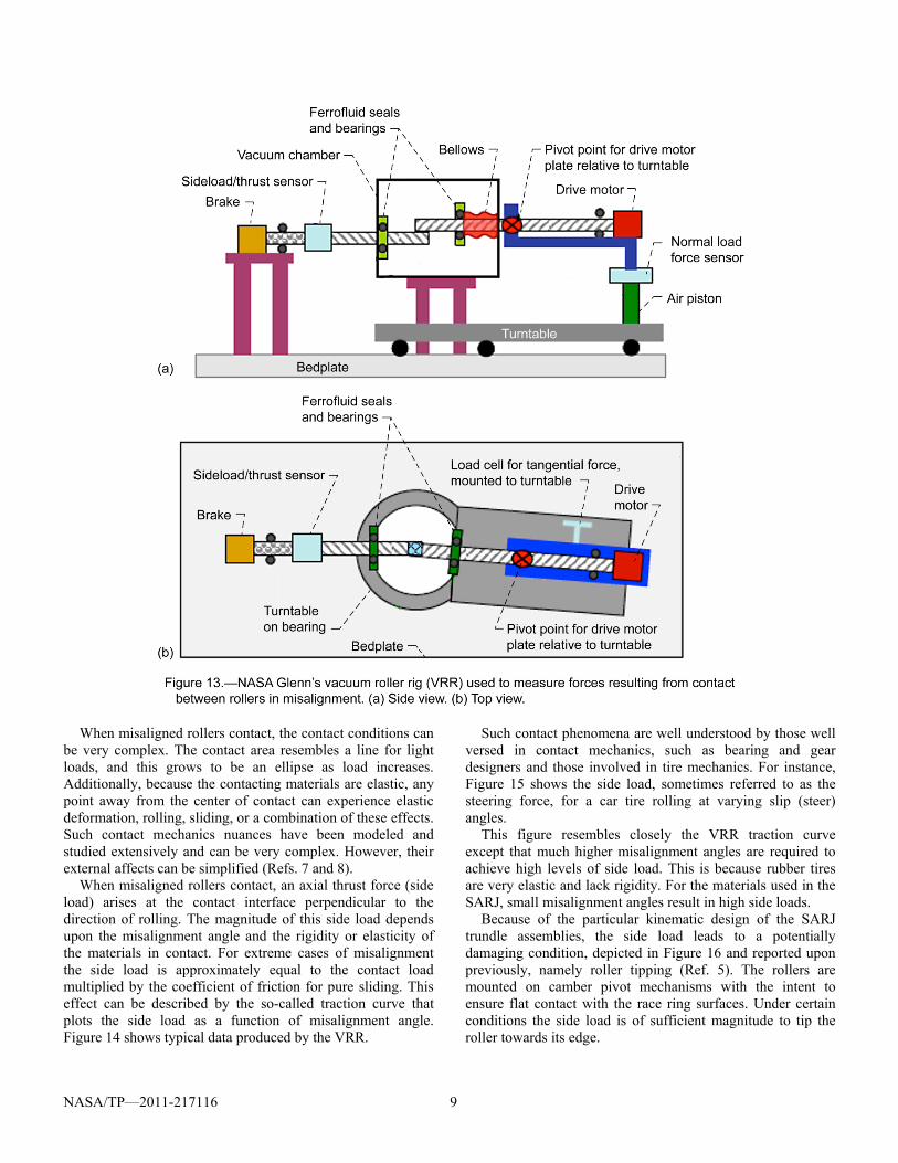
These effects are best described and quantified by the traction tests conducted at NASA Glenn in the vacuum roller rig (VRR). The VRR test loads two cylindrical rollers (Fig. 12) on one another and simulates the contact between the SARJ rollers and the race ring (Ref. 6). As shown in Figure 13, the motor turns the upper roller. The lower roller is driven by the rotation of the upper roller through the small contact that forms between the rollers under load.
With this configuration, one can mimic the SARJ contact, in which small amounts of roller misalignment (less than 1) are inevitable because of tolerance stackups and manufacturing errors (Ref. 5). In essence, the contact is mostly pure rolling with a small sliding component. A key feature of this test is that the rotational axes of the rollers can be parallel (pure rolling) or intentionally misaligned resulting in small but controlled amounts of sliding. The roller supports are well instrumented, and all of the forces and torques that arise from the contact (axial thrust forces and radial side forces) are measured.
NASA/TP—2011-217116 9
When misaligned rollers contact, the contact conditions can be very complex. The contact area resembles a line for light loads, and this grows to be an ellipse as load increases. Additionally, because the contacting materials are elastic, any point away from the center of contact can experience elastic deformation, rolling, sliding, or a combination of these effects. Such contact mechanics nuances have been modeled and studied extensively and can be very complex. However, their external affects can be simplified (Refs. 7 and 8).
When misaligned rollers contact, an axial thrust force (side load) arises at the contact interface perpendicular to the direction of rolling. The magnitude of this side load depends upon the misalignment angle and the rigidity or elasticity of the materials in contact. For extreme cases of misalignment the side load is approximately equal to the contact load multiplied by the coefficient of friction for pure sliding. This effect can be described by the so-called traction curve that plots the side load as a function of misalignment angle. Figure 14 shows typical data produced by the VRR.
Such contact phenomena are well understood by those well versed in contact mechanics, such as bearing and gear designers and those involved in tire mechanics. For instance, Figure 15 shows the side load, sometimes referred to as the steering force, for a car tire rolling at varying slip (steer) angles.
This figure resembles closely the VRR traction curve except that much higher misalignment angles are required to achieve high levels of side load. This is because rubber tires are very elastic and lack rigidity. For the materials used in the SARJ, small misalignment angles result in high side loads.
Because of the particular kinematic design of the SARJ trundle assemblies, the side load leads to a potentially damaging condition, depicted in Figure 16 and reported upon previously, namely roller tipping (Ref. 5). The rollers are mounted on camber pivot mechanisms with the intent to ensure flat contact with the race ring surfaces. Under certain conditions the side load is of sufficient magnitude to tip the roller towards its edge.

NASA/TP—2011-217116 10

NASA/TP—2011-217116 11
Such tipping results in high, localized stresses that could damage the contacting surfaces. Based upon detailed modeling, when the sliding friction coefficient between the roller and race ring reaches 0.4, tipping can occur (Ref. 5).
Figure 17 shows the traction curves for SARJ-like materials as a function of misalignment angle. When lubricants such as gold or grease are present, a maximum friction (traction) coefficient (side load divided by normal load) of about 0.2 is reached at misalignments of about 1.0. (For the SARJ, measurements have confirmed that misalignments were typically less than 0.5). Beyond this point, gross slip inside the contact region prevents higher coefficients and commensurately higher side loads. In other words, good lubrication minimizes the effect. For the unlubricated case,
side loads rapidly build, reaching a maximum at an effective friction (traction) coefficient of about 0.6, well above the level that causes roller tipping. Roller tipping alone leads to very high stresses because the load is concentrated. A second but critical aspect of the trundle kinematic design greatly exacerbates the problem, and that is unexpected rigidity of the trundle preload system.
As shown in Figure 18, each trundle roller is held by its own pivot support. The inner 45 roller is additionally backed by a spring preload system that ensures that the load between the rollers and the race ring are maintained within limits. Should mechanical or thermal distortions occur within a trundle, for instance a large particle or other foreign object on

NASA/TP—2011-217116 12
the race ring being rolled over, the spring preload of the lower roller can accommodate race deflection. In effect, all three rollers are designed to be spring preloaded by the single spring pack located behind the inner 45 roller.
This same design principle is used in single piston-type automotive hydraulic disk brake calipers. In such mechanisms, the hydraulic braking pressure needs only to act upon one pad. Equal and opposite reaction forces are transferred to the opposing pad via the sliding action of the caliper. There are situations, however, in which load sharing does not occur. In such designs, load sharing is dependent upon low friction in the sliding mechanism used to transfer force to the opposing pad. Should this sliding contact experience high friction, load is not shared.
In the SARJ, if the sliding friction coefficient between the rollers and the race surface exceeds about 0.4 the ring can be locked into place much the same way plier jaws lock onto a small, unlubricated round piece of pipe. If some lubricant is applied (low friction) or the pipe diameter is sufficiently large enough to change the jaw angle, the pliers spit the pipe away. In the SARJ, the lack of adequate roller-race surface lubrication (high friction) allowed the outer 45 roller (top right in the figure) to tip against the lower roller (bottom roller in figure) effectively pinching the race ring. This race-ring pinching action combined with a lack of structural compliance caused by high friction, led to greatly increased loads resulting in damaging the nitride surface. Based upon this information, additional modeling, and experimental verification tests, a failure scenario was developed and adopted. It is summarized as follows:
Inadequate lubrication of the roller-race contact combined with a kinematic mechanism design vulnerable to roller tipping and high friction led to damaging high roller-race surface forces and stresses.
This failure scenario provided invaluable guidance to recovery efforts. For instance, the scenario helped explain why the port SARJ that had better lubrication appeared to function nominally while the inadequately lubricated starboard SARJ failed so rapidly. The scenario also enabled modeling and testing efforts to corroborate various pathways to prevent port SARJ failure and to get the starboard side functioning. A clear path for better design of future SARJ-like systems is also revealed. Design elements could include (1) kinematic geometries that will not tip, even in the presence of excessive friction and (2) through the profiling of roller edges to avoid stress concentrations.
SARJ On-Orbit Repair and Recovery
Following the development of the root-cause failure scenario, an on-orbit repair and recovery plan was developed. This plan included an ambitious series of spacewalks to replace damaged trundle arms, the removal of wear debris, and the addition of space-compatible grease to reduce race-roller friction to levels well below those that lead to roller tipping. Design changes to the trundles and race rings could not be reasonably accommodated because of cost, schedule, and practicality reasons.

NASA/TP—2011-217116 13
Figures 19 and 20 show highlights of the SARJ repair and some of the specialized tools used to carry out the tasks. As a testimony to the design team, the SARJ design did allow safe component replacement. In addition, the functioning port SARJ was also lubricated with grease, as there was a concern that several rollers may have had gold film adhesion problems.
It was later determined that there is a corrosion-driven aging effect for gold films deposited on stainless steel. When exposed to room air, gold films will delaminate because of galvanic corrosion at the interface. Since the port SARJ rollers were assembled immediately after gold deposition, they suffered less delamination than the starboard SARJ rollers that
sat for several months after deposition prior to assembly. Interestingly, when the SARJs were restarted after the application of grease, their overall drag torque levels noticeably dropped (see Fig. 21).
This drop was somewhat unexpected because the addition of an extensive layer of grease was thought to be capable of actually increasing drag. Further, a SARJ drag-torque analysis conducted by the original design team had concluded that roller-race sliding friction had no significant effect on overall joint drag-torque (Ref. 9). To better understand this contra-diction, the original torque analysis was examined.

NASA/TP—2011-217116 14
SARJ Torque Analysis
One performance aspect that was addressed during the design and build phase of the project was the anticipated drive torque and power required to rotate the SARJs. Correctly assessing such a parameter was vital in terms of ISS power management since the electrical system and its capacity have direct influence on many vital ISS systems, such as life support, cooling, and research. The SARJ prime contractor did a SARJ drive torque assessment study (Ref. 9).
The study was based upon a first-principles free-body force analysis that took into account roller preload effects, friction between the rollers and the race ring, truss-induced loads, and friction coming from the internal greased tapered roller bearings found inside each trundle roller that enable their free rotation. The in-depth torque study was made available as an internal document and is part of the SARJ records.
The SARJ torque study correctly deduced that the drag torque would arise from several sources: the drive motor gears and bearings, the rolling contact between the trundle rollers and the race rings, and the tapered roller bearings found inside each trundle roller. The drive motor assemblies and the tapered roller bearing friction torques are well understood by engineers. The drag torque of a roller on a race ring is not so straightforward. Figure 22(a) depicts a roller loaded against a race ring surface with a small amount of misalignment. The intentional normal load between the roller and the ring is applied by the spring preload system. This normal load interacts with the rest of the mechanical system causing several other forces to arise.
One key force, the lateral or side force, arises from elastic effects in the contact between the roller and the race surface. For high levels of sliding friction and moderate misalignment angles, the lateral force can reach significant levels, which places an additional load on the internal tapered roller bearings, increasing their drag torque. For the SARJ, this means that a poorly lubricated roller-race ring contact combined with unavoidable misalignment will result in increased overall drag torque. The failure to account for the side load effect on bearing drag led to an incorrect conclusion that roller-race friction (lubrication condition) had no effect on overall SARJ torque, as shown in an excerpt from the original torque study (Ref. 9) reproduced in Figure 22(b).
It is not surprising that a loads engineer or analyst would overlook such contact mechanics phenomena. Only those well versed in mechanical systems that include rolling contact of hard bodies, such as railroad or bearing specialists, would be intimately familiar with these forces (Refs. 7, 8, and 10).
Because of the subtle nature of these contact mechanics, the fact that SARJ drag is indeed affected by roller-race lubrication was not known. During prelaunch ground tests, starboard SARJ drag torque was higher than expected by a factor of about 30 percent. Despite investigating the issue and careful review of subassembly drag values no definitive reason for the high “out-of-family” torque was determined. Because sufficient drive torque margins existed the SARJ was prepared for launch.

NASA/TP—2011-217116 15
Lessons Learned
Complex projects with ambitious and novel goals such as building a SARJ bring challenges in three primary categories: engineering, communications, and validation. Engineers are often well equipped to handle engineering challenges. Meeting challenges in communications and validation can prove more difficult because such topics are less concrete. It is with regard to these two categories, communications and validation, where important lessons learned from the SARJ failure can be gleaned.
When orchestrating large projects involving many people over long periods of time, it can be difficult to maintain effective communications. One important risk often overlooked by those intimately involved with a project or program is ensuring that a clear, consistent, and complete description of the project is developed and maintained for all participants to use for reference. This description can take many forms such as a written document or a briefing package or even a hardware mockup. The existence and continuous dissemination of an official, updated source of project information that enables all project participants, both new and experienced, to share a common vision of the hardware, its intended operation, performance requirements, and terminology makes it less likely that potential problems and warning signs will be overlooked or misunderstood. For
complex systems it is especially important that everyone have a clear, correct, and basic understanding of the entire system so they can see how their own detailed knowledge fits into the whole. For an engineered system like the SARJ, under development at that time, a frequently updated project description document would have been appropriate.
Such a document, however, does not seem to have existed. An early design paper written by NASA researchers best describes the SARJ mechanism (Ref. 3). This paper, which was not widely disseminated, outlined differing conceptual design approaches to building large rotary joints. The actual SARJ design was certainly influenced by this paper, but there were key differences. One difference was that the early conceptual design used the rollers to drive the race ring. In effect, the rollers push the ring in a circle. The final design utilized a gear built into the race that enabled the driven ring to push the rollers. This subtle difference prevents the rollers from self-aligning like a follower-castor wheel and can lead to roller tipping and race-ring pinching (Ref. 5). The conceptual design also took a different approach to the use of “lubricants” for the rollers. In the original design concept, the rollers were intended to drive the ring, and sufficiently high sliding friction was thought to be necessary to prevent roller-race slippage (Ref. 3). Thus, surface traction materials were suggested that could ensure high friction and enduring smooth surfaces as

NASA/TP—2011-217116 16
opposed to the low-friction surfaces actually required by the SARJ. Had a revised design document been written and shared with all participants, some of these more subtle issues may have been discussed and addressed.
The absence of an accurate written description of the mechanism effectively isolated participants working on individual elements of the system. Such compart-mentalizing of participants can reduce project time spent answering questions but also increases the risk that problems may be missed.
Few people involved with the root-cause investigation appeared to have an accurate system-level understanding of how the SARJ worked. Only through arduous study of the build documents and long discussions with various participants could one begin to understand the SARJ operating characteristics. With such a fragmented approach to system-level understanding, when questions arose during the failure investigation about specific components or subassemblies, the team had to rely solely on the input from subject matter experts who also could not see the “big picture.” At times, this input was incorrect. A prime example was the design intent of the gold plating used on the rollers. No written SARJ document clearly defined its role as a friction-reducing film, and few people involved with the failure investigation were even aware that gold could be an effective solid lubricant. This was likely true during the SARJ build. Considering the general lack of system-level understanding, one can more easily see how conditions such as peeling gold films on rollers could have been downplayed during the SARJ build period.
Improving communications so that everyone contributing to a project understands their role, the roles of other contributors, and how the many pieces of a system work together, leads to more robust products. The key step is to make system knowledge fully and continuously available to all and provide sufficient resources to encourage communications amongst personnel at all levels. In today’s more electronic age, this can be effectively done with an information-sharing Web site that could even include a discussion forum, blogs, the most up-to-date project description document, and drawing archives.
Thorough validation, both analytical and experimental, is another important area where more extensive effort would have been a good investment. There are two primary reasons projects conduct validation tests. One is to verify that requirements are met. The other is to develop a better understanding of how a system performs. Customers willingly support tests to prove a system meets requirements. They are less likely to spend resources to develop in-depth understanding. Such understanding is supposed to be solely a function of design. Since design engineers develop their concepts and hardware based upon fixed rules and equations, it is an understandable view that hardware will obey physics. Therefore testing to achieve deeper understanding may appear unnecessary. But when “off-nominal” behavior is observed,
such as higher drive torque than models predict, efforts to understand such discrepancies are resources well spent. Even if tested operating parameters are within margins, unexpected or unexplainable behavior should trigger the need to revisit the models, experiments, and design assumptions until closure is reached. Otherwise, the models and experimental data are in question, and true risks can be more difficult to assess.
Today, testing can take two forms: analytical testing and experimental testing. For simple systems with mild failure consequences, one or the other can be sufficient. For instance, a hand tool like a screwdriver intended for home use could be designed and built with a reliance on modeling and stress analysis. Should it fail, because of poor materials or workmanship, it can be replaced easily. A similar tool destined for use during an EVA outside the ISS would require both analytical and experimental testing because failure consequences could be dire. The materials used for the tool would be proof-tested to verify their yield and ultimate strengths. A flightlike completed tool would be tested to failure to make sure no sharp pieces could become liberated if it were used beyond its limits, lest such debris do harm elsewhere.
Although it might be tempting to utilize one method of testing only, both analytical modeling and experimental validation are essential for critical systems.
In the present case, it may have been possible to set up an inexpensive experiment to validate the SARJ torque model that was based upon analysis (Ref. 9). The model concluded that lubrication of the roller-race interface had a negligible effect on SARJ torque. This could have easily been verified using the structural test article (STA) SARJ, by adding grease and monitoring torque. Conversely, an STA test with unplated rollers could have been conducted to see how the system responded. Unfortunately, analysis was too heavily relied upon, making it difficult for engineers to interpret the distress signals broadcast by the starboard SARJ during prelaunch ground tests.
If project management advocates extensive testing, it can be interpreted as their lack of confidence in the design team. Testing is also expensive and typically occurs late in a project cycle when resources, both time and money, are in short supply. Thus it is not surprising that much testing is aimed at proving that a system meets minimum performance metrics, plus perhaps some design margin. Testing to establish limits and capabilities and testing to intentional failure are rarely done except in cases where human life is involved.
Aircraft design is a field with little room for uncertainty. When a new airframe is being developed extensive full-scale tests are conducted before the first unit ever leaves the ground for a flight test. One key ground test involves static loading of the wings. This is usually done using weighted bags of sand. First the design load is placed upon the wings and their deflection is measured and compared to models. Inspectors are present to make sure the response reasonably agrees with the

NASA/TP—2011-217116 17
models. Then additional weights are added until the design margin—typically twice the rated load—is reached. Again, deflection data are compared to that of the models. The tests up to this point are a good representation of the tests NASA conducted on the SARJ and serve to prove that the design meets minimum and margin requirements. Testing of aircraft goes further, however.
After the aircraft is shown to successfully handle the design and margin loads, additional weights are added and deflection data is collected. Eventually, the wings break in a dramatic fashion. At this point the ultimate load capacity, the failure mode, and the exact location of the failure are verified. The result is then compared to the model results, and any discrepancies are explained. Such testing has proven invaluable in refining models and developing a database that can be used in the event that failure occurs in flight.
Such intentional failure testing has drawbacks, however. One is that the test article is consumed. This can be expensive. Additionally, there is programmatic risk. If the test displays an unexpected result, albeit under conditions outside the design envelope, a redesign may be indicated. This can place more pressure on schedule and cost. Another drawback is political. Dramatic images of broken hardware can be difficult to explain to those outside the team. In our risk adverse times, some feel it is better to avoid failures, even those that are planned.
Nonetheless, without a test to intentional failure, one cannot verify that the design team has accurately predicted the failure mode.
For the SARJ, this is an important lesson to be learned. The failure modes identified by the design team included rolling contact fatigue of the race ring, wear of the drive gear and pinion, foreign object damage (FOD), and failure of the internal tapered roller bearings used in each roller. Backup bushings and electronic rotation indicators were used to monitor the internal bearings. Great care was taken to preclude FOD contamination and ultrahard and strong roller, and race materials were chosen to push the predicted rolling contact fatigue life orders of magnitude beyond ISS needs. A gear life test was run to verify pinion-drive gear wear was acceptable. For this test, the structural test article (STA) was run at heightened speed for an extended time to mimic 13 or more years of SARJ duty. It was then inspected for wear. While it did show signs of uneven roller loading and wear marks, these were not explored further. In effect, the testing that was done was aimed at verifying adequate life and margins for those failure modes that were predicted. Exploratory testing was not conducted to identify unknown failure modes such as roller tipping and pinching of the race ring caused by inadequate lubrication. Such a subtle failure path would have been difficult to predict. It is possible that less purposeful but more inquisitive testing of the STA may have revealed such a failure mode.
Among the tests that could have been performed was an accelerated life test of the STA in a more flightlike
environment. The pinion life test was done in air because utilizing a vacuum test facility large enough to house the full SARJ would have been prohibitively expensive. It is well known that the atmosphere heavily influences tribological behavior. Friction, for example, is often higher in vacuum than in air for bare metal and ceramic interfaces.
The STA could have also been used to validate some of the flight conditions that arose by manufacturing changes and errors. For instance, many of the rollers used for the starboard SARJ had wavy rather than flat surfaces. The decision to accept these rollers was based upon a prediction of their effect upon fatigue life, provided a successful short-term system-level checkout ground test of the SARJ occurred prior to launch. The same philosophy applied to the peeling gold films.
Discussions were held between subcontractors over the effects of wavy roller profiles on performance, but the resolution, again, was led by analysis and engineering judgment rather than experimental verification. Other than the short-term prelaunch ground test, which was done in air,
NASA flew hardware in a condition that was never fully tested.
The STA could have been reconfigured for such a test independent of the build schedule. Anything learned during such independent testing, even after launching the flight hardware, could have proved valuable. Had such testing led to failure, on-orbit greasing of the SARJs could have been done without the extensive cleaning, scraping, and trundle replacement.
Other interesting tests could also be envisioned to address other scenarios. For example, in a ground test one could remove one or more trundles and examine the effect on joint stiffness and operation. Rollers could be intentionally locked and dragged to see the effects on torque and vibration. If such a condition develops on orbit, such ground data can aid in deciphering performance anomalies in orbit to better anticipate problems. To reiterate, more extensive hardware testing provides additional understanding of complex systems and should not be undervalued.
Summary of Results
The forensic engineering investigation presented in this paper identifies missteps that contributed to the SARJ’s failure. Some of these missteps were purely technical while others were more programmatic. Based upon the factors that contributed to the failure and the actions taken to achieve a successful on-orbit repair the following conclusions were drawn and are reiterated below:
(1) Rolling is better than sliding, oils and greases are better than solid lubricants, and traditional solid lubricants (e.g., molybdenum disulfide, polytetrafluoroethylene (PTFE), and engineered and intercalated graphite) are better at reducing friction than metal films.

NASA/TP—2011-217116 18
(2) The best possible design could only have been determined through an extensive experimental and analytical research and development program since such a mechanism—the SARJ—was a first of its kind.
(3) Inadequate lubrication of the roller-race contact combined with a kinematic mechanism design vulnerable to roller tipping and high friction led to damaging high roller-race surface forces and stresses.
(4) The absence of an accurate written description of the mechanism effectively isolated participants working on individual elements of the system. Such compartmentalizing of participants can reduce project time spent answering questions but also increases the risk that problems may be missed.
(5) Although it might be tempting to utilize one method of testing only, both analytical modeling and experimental validation are essential for critical systems.
(6) NASA flew hardware in a condition that was never fully tested.
(7) Despite extensive system analysis and modeling, without a test to intentional failure, one cannot verify that the design team has accurately predicted the failure mode.
Concluding Remarks
NASA’s missions, often the first of their kind, rely upon many engineered systems that are unique and complex and cannot be fully tested before launch. This was most certainly the case for the SARJ mechanisms. This challenges the engineering community to develop approaches to incremental testing and designs that are inherently robust and redundant. In hindsight, one could surmise that the SARJ failure mode could have been anticipated, but this is an unrealistic conclusion. The SARJ is an unusual mechanism that provides an unusual function under unusual conditions. Predicting its failure mode without extensive ground testing is unlikely. To enhance the chances that such vulnerabilities may be uncovered the following recommendations are offered:
A more comprehensive approach to internal engineering communications amongst project participants is essential. Teams of people with varying expertise, duties, and perspectives undertake large, complex systems such as the SARJ. Such projects often span many years and must endure changes of leadership and key personnel as well as utilize many contractors. To avoid overlooking potential problems, each and every contributing participant needs to share a common understanding of the engineered system, its function, and its design. Once achieved it is more likely that the ramifications of a seemingly small manufacturing variance, such as gold film adhesion, will be put in the proper context. Effective communication could take the form of a living, descriptive project overview supplemented by presentations or even an electronic clearinghouse or Web site accessible to all.
Finally, caution must be exercised to avoid reliance upon validation through solely analytical modeling or experimental testing. To minimize risk, both approaches are needed. Such
redundant test approaches should yield consistent results. If a contradictory answer emerges to a common question, its resolution is warranted. In the case of the SARJ, the torque analyses suggested that joint drag was independent from the lubrication condition of the roller-race interface. When the prelaunch ground test yielded higher than expected torque, this non-intuitive, analytical conclusion could have been experimentally verified.
Unfortunately, active and comprehensive communications requires effort and investment. The insistence upon both analytical and experimental testing is also costly. Resource constraints often inhibit such investments. Further, the redundant approach to testing and intentionally testing beyond design conditions to failure can be unpalatable to the very parties that have developed the requirements and design margins. This makes it even more necessary for project leadership to encourage and nurture an open and safe environment where everyone questions everything and criticisms are welcomed. When the consequences for unexpected failure are dire, a thorough approach to testing and development is more effective.
It is hoped that the lessons learned through the SARJ failure and recovery will serve as a teaching aid to reduce system failures on future projects.
Glenn Research Center National Aeronautics and Space Administration Cleveland, Ohio, May 16, 2011
References 1. Catchpole, John E.: The International Space Station: Building
for the Future. Springer, Chichester, UK, 2008. 2. Leger, Lubert J.; and Dufrane, Keith: Space Station Lubrication
Considerations. 21st Aerospace Mechanisms Symposium. NASA CP–2470, 1987, pp. 285–294.
3. Loewenthal, Stuart H.; and Schuller, Fredrick T.: Feasibility Study of a Discrete Bearing/Roller Drive Rotary Joint for the Space Station. NASA TM–88800, 1986.
4. Branda, S.H.: Acceptance Data Package for the SARJ Bearing Assembly Trundles. Document #744D1188, AEC–ABLE Co., Goleta, CA, internal report, Sept. 1997.
5. Harik, Elliot P., et al.: The International Space Station Solar Alpha Rotary Joint Anomaly Investigation. Proceedings of the 40th Aerospace Mechanisms Symposium, NASA/CP—2010-216272, 2010.
6. Krantz, Timothy; DellaCorte, Christopher; and Dube, Michael: Experimental Investigation of Forces Produced by Misaligned Steel Rollers. NASA/TM—2010-216741, 2010.
7. Johnson, K.L.: Contact Mechanics. Cambridge University Press, New York, NY, 1987.
8. Jacobson, Bo O.; and Kalker, J.J.: Rolling Contact Phenomena. CISM Courses and Lectures, no. 411, Springer-Verlag, New York, NY, 2000.
9. Klinker, D.H.: SARJ Torque Margin Update. Lockheed Martin Engineering Memorandum (EM) #02–ME–349–MS–571, internal report, Feb. 1994.
10. McGinnes, H.: Lateral Forces Induced by a Misaligned Roller. Deep Space Network, 1978, pp. 253–257.

REPORT DOCUMENTATION PAGE Form Approved OMB No. 0704-0188
The public reporting burden for this collection of information is estimated to average 1 hour per response, including the time for reviewing instructions, searching existing data sources, gathering and maintaining the data needed, and completing and reviewing the collection of information. Send comments regarding this burden estimate or any other aspect of this collection of information, including suggestions for reducing this burden, to Department of Defense, Washington Headquarters Services, Directorate for Information Operations and Reports (0704-0188), 1215 Jefferson Davis Highway, Suite 1204, Arlington, VA 22202-4302. Respondents should be aware that notwithstanding any other provision of law, no person shall be subject to any penalty for failing to comply with a collection of information if it does not display a currently valid OMB control number. PLEASE DO NOT RETURN YOUR FORM TO THE ABOVE ADDRESS.
1. REPORT DATE (DD-MM-YYYY) 01-08-2011
2. REPORT TYPE Technical Paper
3. DATES COVERED (From - To)
4. TITLE AND SUBTITLE ISS Solar Array Alpha Rotary Joint (SARJ) Bearing Failure and Recovery: Technical and Project Management Lessons Learned
5a. CONTRACT NUMBER
5b. GRANT NUMBER
5c. PROGRAM ELEMENT NUMBER
6. AUTHOR(S) DellaCorte, Christopher; Krantz, Timothy, L.; Dube, Michael, J.
5d. PROJECT NUMBER
5e. TASK NUMBER
5f. WORK UNIT NUMBER WBS 869021.03.07.01.06
7. PERFORMING ORGANIZATION NAME(S) AND ADDRESS(ES) National Aeronautics and Space Administration John H. Glenn Research Center at Lewis Field Cleveland, Ohio 44135-3191
8. PERFORMING ORGANIZATION REPORT NUMBER E-17803
9. SPONSORING/MONITORING AGENCY NAME(S) AND ADDRESS(ES) National Aeronautics and Space Administration Washington, DC 20546-0001
10. SPONSORING/MONITOR'S ACRONYM(S) NASA
11. SPONSORING/MONITORING REPORT NUMBER NASA/TP-2011-217116
12. DISTRIBUTION/AVAILABILITY STATEMENT Unclassified-Unlimited Subject Categories: 18, 37, and 38 Available electronically at http://www.sti.nasa.gov This publication is available from the NASA Center for AeroSpace Information, 443-757-5802
13. SUPPLEMENTARY NOTES
14. ABSTRACT The photovoltaic solar panels on the International Space Station (ISS) track the Sun through continuous rotating motion enabled by large bearings on the main truss called solar array alpha rotary joints (SARJs). In late 2007, shortly after installation, the starboard SARJ had become hard to turn and had to be shut down after exceeding drive current safety limits. The port SARJ, of the same design, had been working well for over 2 years. An exhaustive failure investigation ensued that included multiple extravehicular activities to collect information and samples for engineering forensics, detailed structural and thermal analyses, and a careful review of the build records. The ultimate root cause was determined to be kinematic design vulnerability coupled with inadequate lubrication, and manufacturing flaws; this was corroborated through ground tests, metallurgical studies, and modeling. A highly successful recovery plan was developed and implemented that included replacing worn and damaged components in orbit and applying space-compatible grease to improve lubrication. Beyond the technical aspects, however, lie several key programmatic lessons learned. These lessons, such as running ground tests to intentional failure to experimentally verify failure modes, are reviewed and discussed so they can be applied to future projects to avoid such problems. 15. SUBJECT TERMS Bearings; Lubrication; ISS; Mechanisms; Mechanical engineering; Mechanical drives; Failure analysis; Failure modes; Lessons learned
16. SECURITY CLASSIFICATION OF: 17. LIMITATION OF ABSTRACT UU
18. NUMBER OF PAGES
24
19a. NAME OF RESPONSIBLE PERSON STI Help Desk (email:[email protected])
a. REPORT U
b. ABSTRACT U
c. THIS PAGE U
19b. TELEPHONE NUMBER (include area code) 443-757-5802
Standard Form 298 (Rev. 8-98)Prescribed by ANSI Std. Z39-18