IS 4558 (1995): Under-drainage of lined canals - …IS .4558 : 1995 4.4 Water Table Above Canal FSL...
11
Disclosure to Promote the Right To Information Whereas the Parliament of India has set out to provide a practical regime of right to information for citizens to secure access to information under the control of public authorities, in order to promote transparency and accountability in the working of every public authority, and whereas the attached publication of the Bureau of Indian Standards is of particular interest to the public, particularly disadvantaged communities and those engaged in the pursuit of education and knowledge, the attached public safety standard is made available to promote the timely dissemination of this information in an accurate manner to the public. इंटरनेट मानक “!ान $ एक न’ भारत का +नम-ण” Satyanarayan Gangaram Pitroda “Invent a New India Using Knowledge” “प0रा1 को छोड न’ 5 तरफ” Jawaharlal Nehru “Step Out From the Old to the New” “जान1 का अ+धकार, जी1 का अ+धकार” Mazdoor Kisan Shakti Sangathan “The Right to Information, The Right to Live” “!ान एक ऐसा खजाना > जो कभी च0राया नहB जा सकता ह ै” Bhartṛhari—Nītiśatakam “Knowledge is such a treasure which cannot be stolen” IS 4558 (1995): Under-drainage of lined canals - Code of practice [WRD 13: Canals and Cross Drainage Works]
Transcript of IS 4558 (1995): Under-drainage of lined canals - …IS .4558 : 1995 4.4 Water Table Above Canal FSL...

Disclosure to Promote the Right To Information
Whereas the Parliament of India has set out to provide a practical regime of right to information for citizens to secure access to information under the control of public authorities, in order to promote transparency and accountability in the working of every public authority, and whereas the attached publication of the Bureau of Indian Standards is of particular interest to the public, particularly disadvantaged communities and those engaged in the pursuit of education and knowledge, the attached public safety standard is made available to promote the timely dissemination of this information in an accurate manner to the public.
इंटरनेट मानक
“!ान $ एक न' भारत का +नम-ण”Satyanarayan Gangaram Pitroda
“Invent a New India Using Knowledge”
“प0रा1 को छोड न' 5 तरफ”Jawaharlal Nehru
“Step Out From the Old to the New”
“जान1 का अ+धकार, जी1 का अ+धकार”Mazdoor Kisan Shakti Sangathan
“The Right to Information, The Right to Live”
“!ान एक ऐसा खजाना > जो कभी च0राया नहB जा सकता है”Bhartṛhari—Nītiśatakam
“Knowledge is such a treasure which cannot be stolen”
“Invent a New India Using Knowledge”
है”ह”ह
IS 4558 (1995): Under-drainage of lined canals - Code ofpractice [WRD 13: Canals and Cross Drainage Works]


Indian Standard
UNDER-DRAINAGEOFLINEDCANALS- CODEOFPRACTICE
/ Second Revision )
UDC 626%23*91 : 626.34 : 006.76
BUREAU OF INDIAN STANDARDS MANAK BHAVAN, 9 BAHADUR SHAH ZAFAR MARG
NEW DELHT 110002
August 1995 Price Groop 3

Irrigation Canals and Canal Linings Sectional Committee, RVD 13
FOREWORD
Thus Indian Standard ( Second Revision) was adopted by the Bureau of Indian Standards, after the draft finalized by the Irrigation Canals and Canal Linings Sectional Committee had been approved by the River Valley Division Council.
Where a lined canal crosses areas subject to seasonal high ground water or where the soil is sufficiently water tight to prevent the free draining of the seepage or leakage from the canal, suitable under drainage should be provided to protect the lining. Where the sub-grade is free draining but the area is subject to high ground water, excessive hydrostatic pressure sufficient to damage the lining may develop when the canal is empty or the water level in the canal is relatively low and ground water level is high. A similar situation may occur in areas where the canal is lined for reasons other than to prevent seepage and leakage from the canal. The accumulation of water in the soil surrounding the canal may result in localised high ground water table, which during a period of rapid drawdown of water level in canal may produce damaging hydrostatic back pressure. The water accumulated by means of the under-drainage arrangements used, should be disposed off preferably by means of natural drainage or if this is not available, by use of pressure release valves, into the canal.
This standard was published in 1968 and revised in 1983. This revision has been prepared in the light of experience gained during last six years. In this revision the principal modifications made are in respect of giving specific recommendations for various situations of water table position and type of subgrade. Details of specification for pressure release valves have also been excluded in this revison.
For the purpose of deciding whether a particular requirement of this standard is complied with, the final value, observed or calculated expressing the result of a test or analysis, shall be rounded off in accordance with IS 2 : 1960 ‘Rules for rounding off numerical values ( revised )‘. The number of significant places retained in the rounded off value should be the same as that of the specified value in this standard.

IS 4558 : I995
Indian Standard
UNDER-DRAINAGEOFLINEDCANALS- CODEOFPRACTICE
( Second Revision )
1 SCOPE
1.1 This standard covers methods for under- drainage of lined canals.
1.2 This standard does not cover under- drainage of canals in expansive soils which is given in IS 9451 : 1994.
2 REFERENCES
The following Indian Standards are necessasy adjuncts to this standard:
JS No. Title
4985 : 1988 Specification for UPVC pipes for potable water supply
9451 : 1994 Guidelines for lining of canals in expansive soils
3 VARIOUS CONDiTlONS OF WATER TABLE AND TYPES OF SUBGRADE
3.1 The drainage arrangements to be provided would depend mainly upon the position of the water table and the type of subgrade.
3.2 The water table may have the following positions:
a) Below canal bed level, b) Between canal bed and full supply level,
and c) Above canal full supply level.
3.3 The subgrade may be of the following types:
Free draining - Soil comprising gravel with sand, or sandy soil having permea- bility greater than IO-4 cm/set, that is, K > 10-4 cm/set.
Poor draining - Soil comprising very fine sand, admixlure of sand, silt and clay or soil having permeability between lo-* cm/set and 10-b cm/set, that is, 10-a cm/set < K < IO-4 cm/set.
Practically impervious - Soil comprising homogeneous clays with permeability less than 10-S cm/set, that is, K < 10-e cm/sac.
4 NECESSITY
4.-l Drainage arrangements should be such that the pressure on lining does not increase beyond tha safe limit. Recommended provisions for various conditions are given in 4.2, 4.3 and 4.4.
4.2 Water Table Below Canal Bed Level
a)
b)
Subgrade free draining--- In this eondi- tion there will be no time lag in the dissipation of drawdown pore pressure in the backfill and, as such, no drainage arrangement will be necessary.
Subgradepoor draining - In this condition because of poor draining subgrade, the backfill will get saturated in course of time due to seepage of water through joints and cracks, and should drawdolvn occur, pressure will build up behind the lining. This will necessitate a well designed drainage arrangement.
Subgrade practically impervious - As in 4.2(b) backfill wi!l get saturated in course of time and in drawdown coiidi- tion, excessive pressure will build up behind the lining. In this situation the subgrade should be removed to a depth of 600 mm and replaced by sand, murram or suitable pervious material and a well designed drainage arrangement would be necessary.
4.3 Water Table Between Bed and FSL, and Subgrade Either Free Draining, Poor Draining or Practically Impervious
In this case, the soil behind the lining will remain submerged up to the level of the water table, and in saturated condition above the water table as in 4.2(a) or 4.2(b). The lining will, therefore, be subject to hydrostatic pressure. Well designed drainage arrangements will, therefore, be necessary. However, if subgrade is practically impervious, it should be removed to a depth of 600 mm and replaced by sand, murram or suitable pervious material.
IS .4558 : 1995
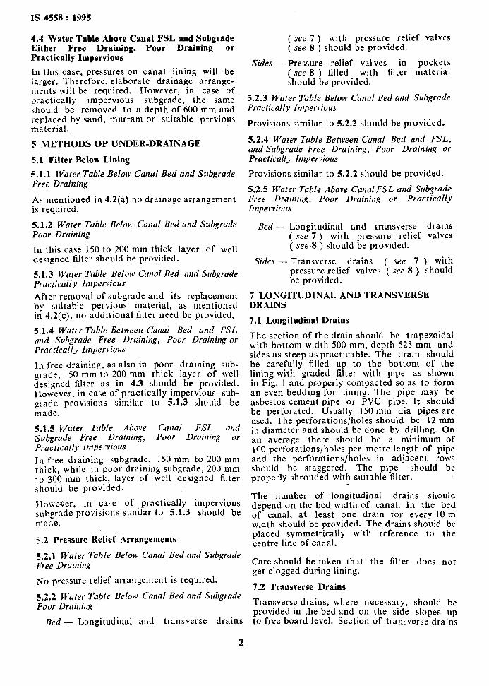
4.4 Water Table Above Canal FSL and Subgrade Either Free Draining, Poor Draining or Practically Impervious
In this case, pressures on canal lining will be larger. Therefore, elaborate drainage arrange- ments will be required. However, inth;as;a;E practically impervious subgrade, should be removed to a depth of 600 mm and replaced by sand, murram or suitable pervious material.
5 METHODS OP UNDER-DRAINAGE
5.1 Filter Below Lining
5.1.1 Water Table Below Canal Bed and Subgrade Free Draining
As mentioned in 4.2(a) no drainage arrangement is required.
5.1.2 Water Table Below Canal Bed and Subgrade Poor Draining
In this case 150 to 200 mm thick layer of well designed filter should be provided.
5.1.3 Water Table Below Canal Bed and Subgrade Practically Impervious After removal of subgrade and its replacement by suitable pervious material, as mentioned in 4.2(c), no additional filter need be provided.
5.1.4 Water Table Between Canal Bed and FSL and Subgrade Free Draining, Poor Draining or Practically Impervious
In free draining, as also in poor draining sub- grade, 150 mm to 200 mm thick layer of well designed filter as in 4.3 should be provided. However, in case of practically impervious sub- grade provisions similar to 5.1.3 should be made.
5.1.5 Water Table Above Canal FSL and Subgrade Free Draining, Poor Draining or Practically Impervious 111 free draining subgrade, 150 mm to 200 mm thick, while in poor draining subgrade, 200 mm to 300 mm thick, layer of well designed filter should be provided.
However, in case of practically impervious subgrade provisions similar to 5.1.3 should be made.
5.2 Pressure Relief Arrangements
5.2.1 Water Table Below Canal Bed and Subgrade Free Drarning
No pressure relief arrangement is required.
5.2.2 Water Table Below Canal Bed and Subgrade Poor Draining
Bed - Longitudinal and transverse drains
3
( see 7 ) with pressure relief valves ( see 8 ) should be provided.
Sides - Pressure relief valves in pockets ( see 8 ) filled with filter material should be provided.
5.2.3 Water Table Below Canal Bed and Subgrade Practically Impervious
Provisions similar to 5.2.2 should be provided.
5.2.4 Water Table Between Canal Bed and FSL, and Subgrade Free Draining, Poor Draining or Practically Impervious
Provisions similar to 5.2.2 should be provided.
5.2.5 Water Table Above Canal FSL and Subgrade Free Drainhg, Poor Draining or Practically Impervious
Bed - Longitudinal and transverse drains ( see 7 ) with pressure relief valves ( see 8 ) should be provided.
Sides - Transverse drains ( see 7 ) with pressure relief valves ( see 8 ) should be provided.
7 LONGITUDINAL AND TRANSVERSE DRAINS
7.1 Longitudinal Drains
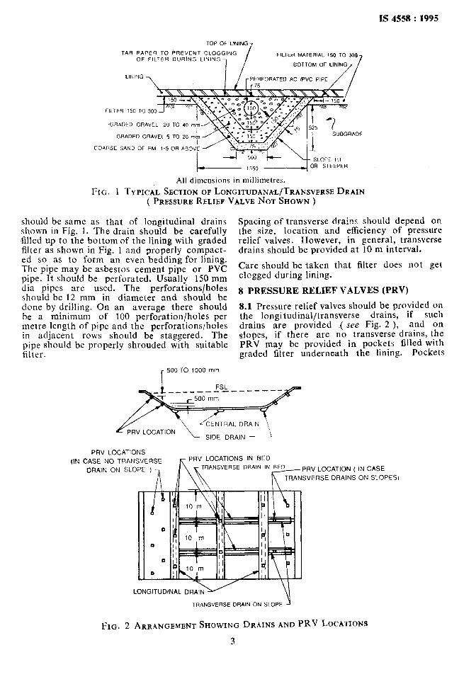
The section of the drain should be trapezoidal with bottom width 500 mm, depth 525 mm and sides as steep as practicable. The drain should be carefully filled up to the bottom of the lining with graded filter with pipe as shown in Fig. 1 and properly compacted so as to form an even bedding for lining. The pipe may be asbestos cement pipe or PVC pipe. It should be perforated. Usually 150 mm dia pipes are used. The perforations/holes should be 12 mm in diameter and should be done by drilling. On an average there should be a minimum of 100 perforations/holes per metre length of pipe and the perforations/holes in adjacent rows should be staggered. The pipe should be properly shrouded with suitable filter.
The number of longitudinal drains should depend on the bed width of canal. In the bed of canal, at least one drain for every 10 m width should be provided. The drains should be placed symmetrically with reference to the centre line of canal.
Care should be taken that the filter does not get clogged during lining.
7.2 Transverse Drains
Transverse drains, where necessary, should be provided in the bed and on the side slopes up to free board level. Section of transverse drains
IS 4558 : 1995
TOP OF LINING 7
TAR PAPER TO PREVFNT CLOGGING OF FILTER DURiNG LINING
FILTER MATERIAL t5Q TO 300
BOTTOM OF LININ,,, /
LINING HFORATED AC /PVC PIP
FILTER 150 TO 30
.GHADED GRAVEL
GRADED GRAVEL 5 TO 20 mm SUBGRADE
COARSE SAND OF FM I-5 OR ABO”
OR SrEEPER
All dimensions in millimetres.
FIG. 1 TYPICAL SECTION OF LONGITUDANA-L/TRANSVERSE DRAIN ( PRESSURE RELIEF VALVE NOT SHOWN )
should be same as that of longitudinal drains shown in Fig. 1. The drain should be carefully filled up to the bottom of the lining with graded filter as shown in Fig. 1 and properly compact- ed so as to form an even bedding for lining. The pipe may be asbestos cement pipe or PVC pipe. It should be perforated. Usually 150 mm dia pipes are used. The perforations/holes should be 12 mm in diameter and should be done by drilling. On an average there should be a minimum of 100 perforation/holes per metre length of pipe and the perforations/holes in adjacent rows should be staggered. The pipe should be properly shrouded with suitable filter.
r 500 TO 1000 mm
Spacing of transverse drains should depend on the size, location and efficiency of pressure relief valves. However, in general, transverse drains should be provided at 10 m interval.
Care should be taken that filter does not get clogged during lining.
8 PRESSURE RELIEF VALVES (PRV)
8.1 Pressure relief valves should be provided on the longitudinal/transverse drains, if such drains are provided ( see Fig. 2 ), and on slopes, if there are no transverse drains, the PRV may be provided in pockets filled with graded filter underneath the lining. Pockets
PRV LOCATIONS
(IN CASE NO TRANSVERSE
DRAIN ON SLOPE 1 RSE DRAIN IN PRV LOCATION ( IN CASE
SVERSE DRAINS ON SLOPESI
LONGITUDINAL DRAI
TRANSVERSE DRAIN ON SLOPE
FIG. 2 ARRANGEMENT SHOWING DRAINS AND PRV LOCATIONS
3

IS 4558 .: 1995
may be square with sides of 600 mm or cylin- drical with diameter 600 mm.
Pockets on slopes should be excavated with their sides at right angles to the slope. The perforated PVC housing pipe for the PRV should be 750 mm long for sides and 430 mm long for bed and should conform to class-2 of IS 4985 : 1988. It should be placed in the centre of the pocket. Graded filter as shown in Fig. 3 should then be carefully placed in the pocket and compacted to form an even bedding for canal lining. Perforations in the housing pipe should be as shown in Fig. 4.
8.2 Placing of PRV’s 8.2.1 Rows In general, one row at every 4 m should be
PRVSOmmQ-7;
provided on the sides. The first row should be about 50 cm above curve line and top row at 50 cm to 100 cm below full supply level. If the water depth is less than l-5 m, one row should be adequate. Valves in adjacent rows should be staggered.
8.2.2 Spacing
In general, one pressure relief valve for every 100 ma should be provided in the canal bed; while on the sides, one pressure relief valve for every 40 rns should be provided. However, the spacing should be decided on this general consideration, keeping in view the site conditions.
GRADiD GRAVEL \20 TO 40
GRADED GRAVEL 5 TO 20
COARSE SAND OF F M
l-5 OR ABOVE
TOP OF LINING
50TTOM OF LINING
160 mm 0 D PVC HOUSING
PIPE (PERFORATED) _/
All dimensions in millimetres.
FIG* 3 PRV POCKETON SLOPS

12
LANGE OF PRV
FLANGE OF HOUSING PI
8 ROWS ALONG PERIPHERY EQUIDISTANT \
R Y HOUSING PIP
ROWS ALONG PERIPHE EQUIDISTANT _-~-
PERFORATED CAP
DETAIL A
I-
IS 4558 : 1995
-!x OD
_ All dimensioix in millimetres. FIG. 4 ~IBTAIL OF PERFORATIONS IN PRV HOUSING PIPE ( DETAIL OF PRV NOT SHOWN )
P
/I- END CAP
5
Bnreao of Indira Standards
BIS is a statutory institution established under the Bureau of Indian Standards Act, 1986 to promote harmonious development of the activities of standardization, marking and quality certification of goods and attending to connected matters in the country.
Copyright
BIS has the copyright of all its publications. No part of these publications may be reproduced in any form without the prior-permission in writing of BIS. This does not preclude the free use, in the course of implementing the standard, of necessary details, such as symbols and sizes, type or grade designations. Enquiries relating to copyright be addressed to the Director ( Publications ), BIS.
Review of Indian Standards
Amendments are issued to standards as the need arises on the basis of comments. Standards are also reviewed periodically; a standard along with amendments is reaffirmed when such review indicates that no changes are needed; if the review indicates that changes are needed, it is taken up for revision. Users of Indian Standards should ascertain that they are in possession of the latest amendments or edition.
This Indian Standard has been developed from Dot No: RVD 13 (63).
Amendments lssaed Since PUbliCatiOD
Amend No. Date of Issue Text Affected
BUREAU OF INDIAN STANDARDS
Headquarters:
Manak Bhavan, 9 Bahadur Shah Zafar Marg, New Delhi 110002 Telegrams : Manaksanstha Telephones : 331 01 31, 331 13 75 ( Common to all offices j
~Regional Offices : Telephone
Central :
Eastern :
Northern
Manak Bhavan, 9 Bahadur Shah Zafar Marg NEW DELHI 110002
l/14 C. I. T. Scheme VII M, V. I. P. Road, Maniktola CALCUTTA 700054
: SC0 335-336, Sector 34-A, CHANDlGARH 160022
Southern : C. I. T. Campus, IV Cross Road, MADRAS600113
331 01 31 33&13 75
I
37 8499, 37 85 61 37 86 26, 37 86 62
I
60 38 43 60 20 25
I
235 02 16, 235 04 42 235 15 19, 235 23 15
Western : Manakalaya, E9 MIDC, Marol, Andheri ( East ) 632 92 95, 632 78 58 BOMBAY 400093 632 78 91, 632 78 92
Branches : AHMADABAD. BANGALORE. BHOPAL. BHUBANESHWAR.
COIMBATORE. FARIDABAD. GHAZIABAD. GUWAHATI. HYDERABAD. JAIPUR. KANPUR. LUCKNOW. PATNA. THIRUVANANTHAPURAM.
Printed at NRW India Prlntine Pram. Khurja. Iadh