IS 2189 (2008): Selection, Installation and Maintenance of … · 2018-11-14 · IS 2189 : 2008...
28
Disclosure to Promote the Right To Information Whereas the Parliament of India has set out to provide a practical regime of right to information for citizens to secure access to information under the control of public authorities, in order to promote transparency and accountability in the working of every public authority, and whereas the attached publication of the Bureau of Indian Standards is of particular interest to the public, particularly disadvantaged communities and those engaged in the pursuit of education and knowledge, the attached public safety standard is made available to promote the timely dissemination of this information in an accurate manner to the public. इंटरनेट मानक “!ान $ एक न’ भारत का +नम-ण” Satyanarayan Gangaram Pitroda “Invent a New India Using Knowledge” “प0रा1 को छोड न’ 5 तरफ” Jawaharlal Nehru “Step Out From the Old to the New” “जान1 का अ+धकार, जी1 का अ+धकार” Mazdoor Kisan Shakti Sangathan “The Right to Information, The Right to Live” “!ान एक ऐसा खजाना > जो कभी च0राया नहB जा सकता ह ै” Bhartṛhari—Nītiśatakam “Knowledge is such a treasure which cannot be stolen” IS 2189 (2008): Selection, Installation and Maintenance of Automatic Fire Detection and Alarm System Code of Practice [CED 22: Fire Fighting]
Transcript of IS 2189 (2008): Selection, Installation and Maintenance of … · 2018-11-14 · IS 2189 : 2008...

Disclosure to Promote the Right To Information
Whereas the Parliament of India has set out to provide a practical regime of right to information for citizens to secure access to information under the control of public authorities, in order to promote transparency and accountability in the working of every public authority, and whereas the attached publication of the Bureau of Indian Standards is of particular interest to the public, particularly disadvantaged communities and those engaged in the pursuit of education and knowledge, the attached public safety standard is made available to promote the timely dissemination of this information in an accurate manner to the public.
इंटरनेट मानक
“!ान $ एक न' भारत का +नम-ण”Satyanarayan Gangaram Pitroda
“Invent a New India Using Knowledge”
“प0रा1 को छोड न' 5 तरफ”Jawaharlal Nehru
“Step Out From the Old to the New”
“जान1 का अ+धकार, जी1 का अ+धकार”Mazdoor Kisan Shakti Sangathan
“The Right to Information, The Right to Live”
“!ान एक ऐसा खजाना > जो कभी च0राया नहB जा सकता है”Bhartṛhari—Nītiśatakam
“Knowledge is such a treasure which cannot be stolen”
“Invent a New India Using Knowledge”
है”ह”ह
IS 2189 (2008): Selection, Installation and Maintenance ofAutomatic Fire Detection and Alarm System Code of Practice[CED 22: Fire Fighting]


IS 2189 : 2008
'J.fN cf) '4 JOfJ 'iCjj
~ 3lfT;f~ q~~cpr~,
m~ q ~-~ - ~ m5ffi(wr~ ~/HUT)
Indian Standard
SELECTION, INSTALLATION ANDMAINTENANCE OF AUTOMATIC FIRE·DETECTION AND ALARM SYSTEM
CODE OF PRACTICE
( Fourth Revision)
ICS 13.220.10
© BIS 2008
BUREAU OF INDIAN STANDARDSMANAK BHAVAN, 9 BAHADUR SHAH ZAFAR MARG
NEW DELHI 110002
April 2008 Price Group 9

Fire Fighting Sectional Committee, CED 22
FOREWORD
This Indian Standard (Fourth Revision) was adopted by the Bureau of Indian Standards, after the draftfinalized by the Fire Fighting Sectional Committee had been approved by the Civil Engineering DivisionCouncil.
The purpose of a fire detection and alarm system is to detect fire at the earliest practicable moment and to give analarm so that appropriate action can be taken (for example, evacuation of occupants, summoning the firefighting organization, triggering ofextinguishing processes, etc). An alarm system may be activated by automaticdetection devices or by manual operation of manual call points.
This standard covering the requirements of heat sensitive fire 'detectors was first published in 1962 and revised in1976, 1988 and 1999. The present revision includes modifications with regard to terminology, inclusion ofprobe type high temperature bi-metal heat detector, optical smoke detector, spark/ember detector, UV flamedetector, IR flame detector etc, and figures for arrangement for smoke detectors and addressable fire detectionand alarm systems.
The general principles given below are for guidance to design and construction of fire detection and alarmsystems. A fire detection and alarm system should:
a) detect quickly enough to fulfil its intended functions;
b) reliably transmit the detection signal;
c) translate this signal into a clear alarm indication that will attract the attention of the user in an immediateand unmistakable way and indicate the location of fire and initiate operation of ancillary service, such asfire extinguishing system, etc;
d) remain insensitive to phenomena other than those where its function is to detect; and
e) signal immediately and clearly and supervise fault that might jeopardize the correct performance of thesystem.
A fire detection and alarm system should be reliable and not liable to disturbance by any other systems whetherassociated with it or not, should not be rendered inoperative partially or totally by the fire or the phenomenonwhich it is designed to detect before the fire or phenomenon has been detected and should be able to fulfil itsfunctions without errors or omissions.
Compliance of components with this standard does not necessarily ensure the compatibility of components witheach other. Compatibility should be considered when designing a system. Satisfactory operation of an installedsystem should be tested after the completion of the installation.
Any fault affecting a part of fire detection and alarm system should not result in cascades of other faults in thesystem as a whole or should not create indirect hazards inside/outside the system.
Multiplexed fire detection system can be used provided the basic operation concepts given in this standard arefulfilled.
For the purpose of deciding whether a particular requirement of this standard is complied with, the final value,observed or calculated, expressing the result of a test or analysis, shall be rounded off in accordance withIS 2: 1960 'Rules for rounding off numerical values (revised)'. The number of significant places retained in therounded off value should be the same as that of the specified value in this standard.

IS 2189 : 2008
Indian Standard
SELECTION, INSTALLATION ANDMAINTENANCE OF AUTOMATIC FIREDETECTION AND ALARM SYSTEM
CODE OF PRACTICE
( Fourth Revision)1 SCOPE 3 TERMINOLOGY
2 REFERENCES
1.2 This standard covers minimum level ofprotection.Nothing in this standard prevents to install systemsdesigned for higher degree of protection, for specialrisks, etc.
The standards listed below contain provisions which,through reference in this text, constitute provisions ofthis standard. At the time of publication, the editionsindicated were valid. All standards are subject torevision and parties to agreements based on thisstandard are encouraged to investigate the possibilityof applying the most recent editions of the standardsindicated below:
1.1 This standard covers the planning, design,selection, installation and maintenance oftire detectionand alarm systems. It is applicable to simple systemswith a few manual call points as well as to complexinstallations comprising addressable control andindicating panel, non-addressable detectors, manualcall points, control and indication panels. It coverssystems capable of providing signals to initiate, in theevent ofa fire, the operation ofancillary services, suchas fire extinguishing systems and other necessaryprecautions but it does not cover the ancillary services.It covers tire detection and alarm system installed inbuildings of different types including those installedin industries.
3.8 Analog Initiating Device (Sensor) - An initiatingdevice that transmits a signal indicating varyingdegrees ofconditions as contrasted with a conventionalinitiating device which can only indicate an on-offcondition.
3.1 Acknowledge - To contirm that a message orsignal has been received, such as by the pressing of abutton or the selection of a software command.
3.9 Annunciator - A unit containing one or more
3.2 Activation Device (Trigger Device) - Devicecapable of being operated automatically or manuallyto initiate an alarm that is, detector, a manual (tirealarm) call point or a pressure switch.
3.3 Addressable Device - A fire alarm systemcomponent with discrete identitication that can haveits status individually identitied or that is used toindividually control other functions.
3.4 Addressable System - System in which signalsfrom detectors, manual call points, or any other devicesare individually identitied at the control and indicatingequipment.
3.5 Air Sampling-Type Detector - A detector thatconsists of a piping or tubing distribution network thatruns from the detector to the area(s) to be protected.An aspiration fan in the detector housing draws airfrom the protected area back to the detector throughair sampling ports, piping, or tubing. At the detector,the air is analyzed for tire products.
3.6 Alarm Zone - Geographical sub-division of theprotected premises, in which the tire alarm warningcan be given separately, and independently, of a firealarm warning in any other alarm zone.
3.7 Alert Tone - An attention getting signal to alertoccupants of the pending transmission of a voicemessage.
3.0 For the purpose of this standard, the followingdetinitions and definitions given in IS 8757 shallapply.
Title
Specitication for heat sensitive firedetectors for use in automatic firealarm system (second revision)
Glossary of terms associated withtire safety (first revision)
Specitication for smoke detectors foruse in automatic electrical tire alarmsystem
Code of practice for tire protectionof electronic data processinginstallations
IS No.
11360: 1985
12456: 1988
2175: 1988
8757: 1999

IS 2189: 2008
indicator lamps, alphanumeric displays, graphicaldisplays or other equivalent means in which eachindication provides status information about a circuit,condition or location.
3.10 Approved - Acceptable to the authority havingjurisdiction.
3.11 Audibility - Property of a sound which allowsit to be heard among other sounds in the.background.
3.12 Authority having Jurisdiction - Theorganization, office, or individual responsible forapproving equipment, materials, an installation or aprocedure.
3.13 Automatic Fire Detection and AlarmSystem - Fire alarm system comprising componentsand sub-system required for automatically detecting afire, initiating an automatic alarm for fire and initiatingother action as required.
3.14 Automatic Fire Signal- Alarm of fire originatedby an automatic device, given audibly and/or visibly.
NOTE- The system may also includemanualfire alarmcallpoints.
3.15 Ceiling - The upper surface ofa space, regardlessof height. Areas with a suspended ceiling have twoceilings, one visible from the floor and one above thesuspended ceiling.
3.16 Ceiling Height - The height from the continuousfloor of a room to the continuous ceiling of a room orspace.
3.17 Circuit - Assembly of fire alarm componentssupplied from the same control equipment andprotected against overcurrent by the same protectivedevice(s) or current limitation arrangements.
3.18 Circulation Area - Area (including a stairway)used mainly as a means of access between a room andan exit from the building or compartment.
3.19 Combination/Multifunction Detector - Adevice that either responds to more than one of the firephenomena or employs more than one operatingprinciple to sense one of these phenomena. Typicalexamples are a combination of a heat detector with asmoke detector or a combination of rate-of-rise andfixed-temperature heat detector.
3.20 Commissioning - Process by which it isdetermined that the installed system meets thedefined requirements.
3.21 Control Centre - Permanently staffed roomwithin or near the premises at risk for the receipt ofemergency calls and equipped with means forindicating the situation in each of the protectedpremises, and the communications needed for
2
transmission of calls for assistance to emergencyservices.
3.22 Control Unit - A system component thatmonitors inputs and controls outputs through varioustypes of circuits.
3.23 Detection Zone - Sub-division of the protectedpremises such that the occurrence of fire within it willbe indicated by a fire alarm system separately from anindication of fire in any other sub-division.
3.24 Detector - A device suitable for connection to acircuit that has a sensor that responds to a physicalstimulus such as heat or smoke or flame.
3.25 Display - The visual representation of outputdata, other than printed copy.
3.26 Electrical Conductivity Heat Detector - Aline-type or spot-type sensing element in whichresistance varies as a function of temperature.
3.27 Ember - A particle of solid material that emitsradiant energy due to either its temperature or theprocess of combustion on its surface.
3.28 Emergency Voice/Alarm Communications Dedicated manual or automatic facilities for originatingand distributing voice instructions, as well as alert andevacuation signals pertaining to a fire emergency, tothe occupants of a building.
3.29 Evacuation - The withdrawal ofoccupants froma building.
3.30 Evacuation Signal- Distinctive signal intendedto be recognized by the occupants as requiringevacuation of the building.
3.31 Exit Plan - A plan for the emergency evacuationof the premises.
3.32 False Alarm - Alarm of fire that is, false,because the fire reported does not and did not exist.This false alarm may arise by malicious, mistaken oraccidental intent.
3.33 Fault Signal - A distinctive audible and visualsignal indicating occurrence of a fault within thesystem (for example, break in electric circuit, shortcircuit or fault in power supply).
3.34 Fire Alarm Control and IndicatingEquipment - Equipment through which firedetectors may be supplied with power and which:
a) is used to accept a detection signal and actuatea fire alarm signal;
b) is able to pass on the fire detection signal,through the fire alarm routing equipment, tothe fire fighting organization or to automaticextinguishers;

c) is used to monitor automatically the correctfunctioning of the system; and
d) is used to indicate or display the location offire/alarm activation device.
3.35 Fire Alarm Signal - A signal initiated by afire alarm-initiating device, such as a manual fire alarmbox, automatic fire detector, water flow switch, orother device in which activation is indicative of thepresence of a fire or fire signature.
3.36 Fire Alarm System - A combination ofcomponents for giving an audible and visible and/orother perceptible alarm of fire. The system may alsoinitiate other ancillary action.
3.37 Fire Rating - The classification indicating intime (hours) the ability ofa structure or component towithstand a standardized fire test. This classificationdoes not necessarily reflect performance of ratedcomponents in an actual fire.
3.38 Fire Safety Functions - Building and firecontrol functions that are intended to increase the levelof life safety for occupants or to control the spread ofthe harmful effects of fire.
3.39 Fixed Temperature Detector - A device thatresponds when its operating element becomes heatedto a predetermined level.
3.40 Flame - A body or stream of gaseous materialinvolved in the combustion process and emittingradiant energy at specific wavelength bands determinedby the combustion chemistry ofthe fuel. In most cases,some portion of the emitted radiant energy is visibleto the human eye.
3.4 t Flame Detector - A radiant energy-sensingfire detector that detects the radiant energy emitted bythe flame.
3.42 Flame Detector Sensitivity - The distancealong the optical axis of the detector at which thedetector can detect a fire of specified size and fuelwithin a given time frame.
3.43 Floor - Area contained on each storey of thebuilding.
3.44 Heat Detector - A fire detector that detectseither abnormally high temperature or rate oftemperature rise, or both.
3.45 Ionization Smoke Detection - The principle ofusing a small amount of radioactive material toionize the air between two differentially chargedelectrodes to sense the presence of smoke particles.Smoke particles entering the ionization volumedecrease the conductance of the air by reducingion mobility. The reduced conductance signal is
3
IS 2189 : 2008
processed and used to convey an alarm condition whenit meets preset criteria.
NOTE - It is suggested that the use of such detectors bediscouraged/avoided, as they have a radioactive source. Multifunction detectors may be used instead.
3.46 Line Detector - Detector which responds to thephenomenon sensed in the vicinity of a continuousline.
3.47 Maintenance - Repair service, includingperiodic inspections and tests, required to keep the firealarm system and its component parts in an operativecondition at all times, and the replacement ofthe systemor its components when they become undependable orinoperable for any reason.
3.48 Manual Call Point - A manually operateddevice used to initiate analarm signal. Itcanbe manualalarm system or part of automatic alarm system. .
3.49 Mimic Panel - A panel in which the floor/areaplans of the premises are projected to reduced scale toenable easy identification of the sector/zone.
3.50 Multi-Sensor Fire Detector - Fire detector thatmonitors more than one physical and/or chemicalphenomenon associated with fire. Typical examples area combination of a heat and smoke detector orcombination of heat and gas detectors.
3.51 Photoelectric Light Obscuration SmokeDetection - The principle of using a light sourceand a photosensitive sensor onto which theprincipal portion of the source emissions is focused.When smoke particles enter the light path, some ofthe light is scattered and some is absorbed, therebyreducing the light reaching the receiving sensor.The light reduction signal is processed and used toconvey an alarm condition when it meets presetcriteria.
3.52 Photoelectric Light-Scattering SmokeDetection - The principle ofusing a light source anda photosensitive sensor arranged so that the rays fromthe light source do not normally fall onto thephotosensitive sensor. When smoke particles enter thelight path, some of the light is scattered by reflectionand refraction onto the sensor. The light signal isprocessed and used to convey an alarm condition whenit meets preset criteria.
3.53 Point Detector - Detector which responds tothe phenomenon sensed in the vicinity of a fixedpoint.
3.54 Power Supply - A source ofelectrical operatingpower, including the circuits and terminals connectingit to the dependent system components.
3.55 Projected Beam-Type Detector - A type ofphotoelectric light obscuration smoke detectorwherein the beam spans the protected area.

IS 2189: 2008
3.56 Protected Premises - The physical locationprotected by a fire alarm system.
3.57 Radio Alarm System (RAS) - A system inwhich signals are transmitted from a radio alarmtransmitter (RAT) located at the protected premisesthrough a radio channel to two or more radio alarmrepeater station receivers (RARSR) and that areannunciated by a radio alarm supervising stationreceiver (RASSR) located at the central station.
3.58 Rate-of-Rise Detector - A device that respondswhen the temperature rises at a rate exceeding apredetermined value.
3.59 Search Distance - Distance which has to betravelled by a searcher within a zone in order todetermine visually the position of fire.
3.60 Sector - A sub-division of the protectedpremises larger than a zone. A larger floor may bedemarcated into sectors, that is, addressed part of thefloor. A sector will normally contain many zones.
3.6] Shapes of Ceilings - The shapes ofceilings canbe classified as sloping or smooth.
3.62 Short Circuit Isolators - Devices which maybe connected into a transmission path ofa fire detectionand fire alarm system, to limit the consequences oflow parallel resistance faults between the lines of thistransmission path.
3.63 Sloping Ceiling - A ceiling that has a slope.
3.64 Smoke Detector - A device that detects visibleor invisible particles of combustion.
3.65 Smooth Ceiling - A ceiling surfaceuninterrupted by continuous projections, such as solidjoists, beams, or ducts, extending more than 100 mmbelow the ceiling surface.
3.66 Spacing - A horizontally measured dimensionrelated to the allowable coverage of fire detectors.
3.67 Spark - A moving ember.
3.68 Spark/Ember Detector - A radiant energysensing fire detector that is designed to detect sparksor embers, or both. These devices are normallyintended to operate in dark environments and in theinfra-red part of the spectrum.
3.69 Spark/Ember Detector Sensitivity - Thenumber of watts (or the fraction of a watt) ofradiant power from a point source radiator, applied asa unit step signal at the wavelength of maximumdetector sensitivity, necessary to produce an alarmsignal from the detector within the specified responsetime.
3.70 Standby Supply - Power supply,commonly froma rechargeable battery, which is automatically
4
connected to the fire alarm system when the normalpower supply fails.
3.71 Trouble Signal - A signal initiated by the firealarm system or device indicative of a fault in amonitored circuit or component.
3.72 Zone - Area or space that has a group ofautomatic and/or non-automatic fire detection devicesfor which there is a separate common display in thecontrol and indicating equipment.
4 GENERAL REQUIREMENTS
4.1 Automatic fire detection and alarm system consistsof fire detectors and manual call points connected byappropriate cables to sector/zonal panels which in tumare connected to control and indicating equipment(C and I). The equipment and cables of automatic firedetection and alarm system should be independent ofany other system or cables, and should not be sharedwith any other system.
NOTE - Where analog addressable fire alarm system isused, which consists of addressable devices and suitable controlpanel, zoning and number ofdetectors shall be as per 4.2.4.
4.1.1 If the requirement ofdetectors in any area is lessthan 20, division into zones/sectors may not benecessary. Similarly, sectorization may not benecessary if the number of zones is not very large andin case ofbigger premises, the premises may be dividedinto wings and each wing may have sectors/zones.
4.1.2 Size of the conventional panels is normallyreferred by number of zones. Each zone can beconnected with the conventional detectors notexceeding 20.
4.2 Detection Zones
4.2.1 General
a) In most of the buildings an alarm of fire mayinitiate a number of different activities, forexample,provision ofassistance, commencementof fire fighting operations and emergencyevacuation procedures, summoning of firebrigade, etc. It is essential that these activitiesare well co-ordinated. In the pre-planning ofemergency procedures for a building it istherefore important, for ease of communicationand synchronization ofeffort, to fix a convenientnumber of easily identifiable sectors/zones,which the building can be divided.
b) In order to direct those responding to a fire alarmsignal to the area of fire, all buildings with theexception of smaller ones need to be dividedinto detection zones. The zones need to be smallenough for a fire to be located quickly. Even ifthe system is addressable, zoning indicationsneeds to be provided as this often provides aquicker indication of the location of a fire than

typical addressable text displays. Zoneindicators also provide a simple 'at a glance'overview of the extent of fire or smoke spread.Also this would enable fire fighters who are notfamiliar with the building to proceed to thelocation of fire.
4.2.2 Requirements for detection zones that containnon-addressable automatic detection system are givenbelow:
a) The floor area of a single zone shall not exceed2000 m2
•
b) If the total area of a building is less than300 rn-, a zone can cover more than one floor.
c) If the total area of a building is more than300 m', each zone shall be restricted toa singlefloor.
d) Voids, if any, above or below the floor area ofaroom can be included in the same zone as of theroom provided that the voids and the roomconstitute a single compartment.
e) The search distance, that is, the distance thathas to be travelled by anyone responding to afire alarm signal after entry to the zone in orderfor the location of the fire to be determinedvisually, shall not exceed 30 m.
t) Automatic fire detectors within any enclosedstairwell, lift well or other enclosed shaft-likestructures shall be considered as a separate zone.
g) If manual call points are located on the landingsofan enclosed staircase, such points at each levelshall be incorporated within the zone that servesthe adjacent accommodation on that level.
h) The detectors and manual call points withinsectors/zones shall be wired to the control andindicating equipment.
j) The entire electrical installation pertaining tothe entire fire alarm system as described aboveshall be independent of other systems.
k) When a signal of fire is given it is necessarythat there shall be no confusion about the zonefrom which it is received.
m) To facilitate response by persons providingassistance, the zone shall be small enough for afire located quickly.
n) It is advisable to provide adequate fire separationbetween the zones.
p) In larger premises, the fire alarm system shallbe so designed and arranged that it is fullycompatible with the emergency procedures andprovides at some central or convenient point,or points, an indication of the zone from whichan alarm has originated.
q) In the case of two stage alarms, clear andunambiguous signals shall indicate the
5
IS 2189: 2008
emergency procedure to be adopted throughouteach zone.
r) If the requirement of detectors or call points isless than 20 in any area, division of the areainto zones is not necessary. Similarly,sectorization is not necessary if the number ofzones is not very large.
s) For larger systems covering more than onebuilding it may be necessary to create sectors inaddition to zones in order to restrict the numberof zones from which alarms originatesimultaneously or in succession.
t) It is not always possible to provide definiteguidelines regarding the requirements for thedivision of sectors, etc, as stated above due tothe fact that the configurations are not same forall risks. The division into zones and/or sectorsshall be decided based on careful considerationon the type of risk and accessibility of zonesin respect of main circulation routes and themain control and indicating equipment.
u) In general, the signals used in different zonesin the same premises shall be the same unlessthe background noise in one or more zones issuch as to require different sounders.
v) The zoning arrangement for systems in multipleoccupations shall take into account the factthat all the premises may not be occupied at thesame time. No zone shall include areas in morethan one occupancy.
w) Remote indicator lamps outside doors ofrooms, cabins, etc, within a zone may be useful,if doors are likely to be locked. Making an areaeasier to search, the us.e of remote indicatorlamps reduce the need for a large number ofsmaller zones.
x) Where a special risk is present within a largeprotected area, for example, a spray paintingboth in engineering workshop and it isconsidered important to obtain rapididentification of fire in that risk, such specialrisk shall be deemed as a separate zone.
y) Where a zone extends beyond a singlecompartment, the zone boundaries shall be theboundaries of the fire compartments.
NOTES
1 It ispermissibleto havetwocompletefirecompartmentsinonezone,or twocompletezones inone firecompartment.
2 Itis notpermissible tohavea zone,whichextendsintopartsof twocompartments,or a compartment,which extends intopartsoftwozones.
z) If the arrangement of an area is complex andtime is likely to be wasted in search for the fire,notwithstanding any limits shown above, thearea shall be further sub-divided into zones thatare easier to search.
IS 2189: 2008
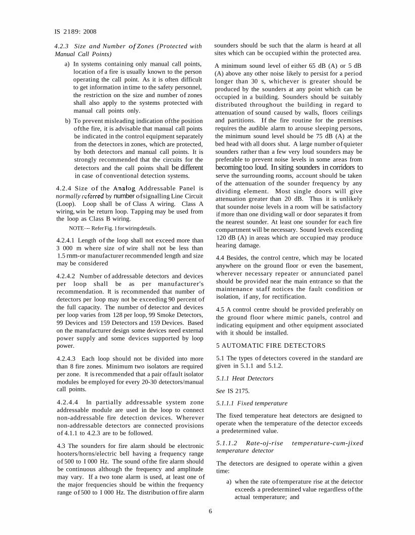
4.2.3 Size and Number of Zones (Protected withManual Call Points)
a) In systems containing only manual call points,location of a fire is usually known to the personoperating the call point. As it is often difficultto get information in time to the safety personnel,the restriction on the size and number of zonesshall also apply to the systems protected withmanual call points only.
b) To prevent misleading indication ofthe positionofthe fire, it is advisable that manual call pointsbe indicated in the control equipment separatelyfrom the detectors in zones, which are protected,by both detectors and manual call points. It isstrongly recommended that the circuits for thedetectors and the call points shall be differentin case of conventional detection systems.
4.2.4 Size of the Analog. Addressable Panel isnormally referred by number ofsignalling Line Circuit(Loop). Loop shall be of Class A wiring. Class Awiring, win be return loop. Tapping may be used fromthe loop as Class B wiring.
NOTE- ReferFig. 1for wiringdetails.
4.2.4.1 Length of the loop shall not exceed more than3 000 m where size of wire shall not be less than1.5 rnm-or manufacturer recommended length and sizemay be considered
4.2.4.2 Number of addressable detectors and devicesper loop shall be as per manufacturer'srecommendation. It is recommended that number ofdetectors per loop may not be exceeding 90 percent ofthe full capacity. The number of detector and devicesper loop varies from 128 per loop, 99 Smoke Detectors,99 Devices and 159 Detectors and 159 Devices. Basedon the manufacturer design some devices need externalpower supply and some devices supported by looppower.
4.2.4.3 Each loop should not be divided into morethan 8 fire zones. Minimum two isolators are requiredper zone. It is recommended that a pair offault isolatormodules be employed for every 20-30 detectors/manualcall points.
4.2.4.4 In partially addressable system zoneaddressable module are used in the loop to connectnon-addressable fire detection devices. Wherevernon-addressable detectors are connected provisionsof 4.1.1 to 4.2.3 are to be followed.
4.3 The sounders for fire alarm should be electronichooters/horns/electric bell having a frequency rangeof 500 to I 000 Hz. The sound ofthe fire alarm shouldbe continuous although the frequency and amplitudemay vary. If a two tone alarm is used, at least one ofthe major frequencies should be within the frequencyrange of500 to I 000 Hz. The distribution of fire alarm
6
sounders should be such that the alarm is heard at allsites which can be occupied within the protected area.
A minimum sound level of either 65 dB (A) or 5 dB(A) above any other noise likely to persist for a periodlonger than 30 s, whichever is greater should beproduced by the sounders at any point which can beoccupied in a building. Sounders should be suitablydistributed throughout the building in regard toattenuation of sound caused by walls, floors ceilingsand partitions. If the fire routine for the premisesrequires the audible alarm to arouse sleeping persons,the minimum sound level should be 75 dB (A) at thebed head with all doors shut. A large number ofquietersounders rather than a few very loud sounders may bepreferable to prevent noise levels in some areas frombecoming too loud. In siting sounders in corridors toserve the surrounding rooms, account should be takenof the attenuation of the sounder frequency by anydividing element. Most single doors will giveattenuation greater than 20 dB. Thus it is unlikelythat sounder noise levels in a room will be satisfactoryif more than one dividing wall or door separates it fromthe nearest sounder. At least one sounder for each firecompartment will be necessary. Sound levels exceeding120 dB (A) in areas which are occupied may producehearing damage.
4.4 Besides, the control centre, which may be locatedanywhere on the ground floor or even the basement,wherever necessary repeater or annunciated panelshould be provided near the main entrance so that themaintenance staff notices the fault condition orisolation, if any, for rectification.
4.5 A control centre should be provided preferably onthe ground floor where mimic panels, control andindicating equipment and other equipment associatedwith it should be installed.
5 AUTOMATIC FIRE DETECTORS
5.1 The types of detectors covered in the standard aregiven in 5.1.1 and 5.1.2.
5.1.1 Heat Detectors
See IS 2175.
5.1.1.1 Fixed temperature
The fixed temperature heat detectors are designed tooperate when the temperature of the detector exceedsa predetermined value.
5.1.1.2 Rate-oj-rise temperature-cum-jixedtemperature detector
The detectors are designed to operate within a giventime:
a) when the rate of temperature rise at the detectorexceeds a predetermined value regardless of theactual temperature; and

IS 2189: 2008
CONVENTIONAL (NON - ADDRESSABLE)DETECTION SYSTEM - CLASS B WIRING
CONTROLUNITINITIATINGDEVICECIRCUIT
rC>l-_-=D::ETECTOR BAS__E D_E"TECTOR BA_SE ... END OF LINE
,. RESISTOR
1A Correct Wiring Method - Two-Wire Detectors
CONVENTIONAL (NON - ADDRESSABLE)DETECTION SYSTEM· CLASS B WIRING
CIRCUIT WIRING BENTBACK ON ITSELF ANDSECURED IN ONE NOTCH
CIRCUIT WIRINGLOOPED UNDERONE TERMINAL
CONTROLUNITINITIATINGDEVICECIRCUIT o+ --1IL.-. J'-- ......
r----~---...,r--------...,r--------, END OF LINERESISTOR
1B Incorrect Wiring Method - Two-Wire Detectors
RELAY I CONTROLMODULE
24VDC
* LOOP POWERED HOOTER I SOUNDEROR
*SEPARATE POWERED HOOTER
1C Addressable Fire Detection and Alarm System - Class A Wiring
7

IS 2189: 2008
ZONE ADDRESSABLEMODULE
ADDRESSABLEPULL STATION
* LOOP POWERED HOOTER I SOUNDEROR
*SEPARATE POWERED HOOTER
RELAY I CONTROLMODULE
HOOTER
1D Addressable Fire Detection and Alarm System - Class A Wiring with Class B Tapping
FIG. 1 WIRING DETAILS FOR FIRE DETECTION AND ALARM SYSTEM
b) when temperature at the detector exceeds apredetermined value.
5.1.1.3 Probe type high temperature hi-metal heatdetector
Bi-metal heat detectors are resettable and highlysuitable to use above 80°C where electroniccomponents cannot be used. The following are type ofapplication for which probe type high temperature heatdetectors are suitable.
Generator enclosure, turbine enclosure, oven andfurnace area, kitchen wood and other places as per therequirement where automatic fire extinguishing/suppression systems are used.
5.1.1.4 Linear heat sensing cables
Linear heat sensing cables can be broadly divided intotwo categories. Digital or analogue, depending uponthe principle by which the sensing cable registers achange in temperature.
Digital sensor consists of two core cable in which theconductors are separated by a heat sensitive insulator.When a specified temperature is reached, the cableinsulation breaks down and an alarm is indicated. Inthe case of analogue sensor, cores are separated by anegative temperature co-efficient polymer whoseresistance will reduce in proportion to the temperatureincrease.
8
These cables are used for detecting fire and overheatingin certain specific occupancies such as:
a) cables tunnels, trays and vaults;
b) material conveyors;
c) bulk storage multi-racked areas;
d) rim seals offloating rooftanks storing hazardouschemicals; and
e) a few other special occupancies.
5.1.1.5 Heat detectors application
These are suitable for use in situation where sufficientheat is likely to be generated and damage caused byheat generated by the fire constitutes main hazard. Thisis to be minimized through early detection. In manybuildings, especially non-air-conditioned buildings,these conditions prevail where heat detectors can beadvantageously used. Heat detectors are however, notsuitable for protection of places where larger lossescan be caused by small fires and where safety of life isinvolved.
5.1.2 Smoke Detectors
See IS 11360.
5.1.2.1 Ionization smoke detectors
Detectors employing ionization chamber(s) as sensingmeans for detecting aerosols given-off by fires.

5.1.2.2 Optical (photoelectric) smoke detectors
A detector whose operation is based on lightattenuation by smoke and/or light scattering by smokeparticles.
5.1.3 Air Sampling Type Detector
Laser type smoke detectors are used in this type ofdetection system. A detector that consists of a pipingor tubing distribution network that runs from thedetector to the areas to be protected. An aspiration fanin the detector housing draws air from the protectedarea back to the detector through air sampling ports,piping or tubing. At the detector, the air is analyzedfor fire products. Typical application of the systems iswhere a trace of smoke needs to be detected, wherehigh airflow can make traditional smoke detectorinadequate.
5.1.3.1 Smoke detectors application
Ionization smoke detectors respond quickly tosmoke containing small particles normally producedin clean burning fires, but may respond slowly tooptically dense smoke which may be produced bysmouldering materials. Certain materials like PVC,when overheated, produced mainly large particles towhich ionization detectors are less sensitive. Opticalsmoke detectors respond quickly to smoke, that isoptically dense. Both types of detectors have asufficiently wide range of responses to be of generaluse. While selecting the detector, 5.2 to be taken intoaccount.
5.1.4 Spark/Ember Detector
A spark/ember-sensing detector usually uses a solidstate photodiode or phototransistor to sense theradiant energy emitted by embers. Typicallybetween 0.5 Il and 2.0 Il in normally dark environments. These detectors can be made extremely sensitive(microwatts), and their response times can be madevery short (microseconds). Spark/ember detectors areinstalled primarily to detect sparks and embers thatcould, if allowed to continue to bum, precipitate a muchlarger fire or explosion. Spark/ember detectors aretypically mounted on some form of duct or conveyor,monitoring the fuel as it passes by. Usually, it isnecessary to enclose the portion ofthe conveyor wherethe detectors are located, as these devices generallyrequire a dark environment. Extraneous sources ofradiant emissions that have been identified asinterfering with the stability of spark/ember detectorsinclude the following:
a) Ambient light;
b) Electromagnetic interference (EMI, RFI);and
c) Electrostatic discharge in the fuel stream.
9
IS 2189 : 2008
5.1.5 UV Flame Detector
UV Flame detector makes use of ultraviolet sensitivephotocathode for detecting flame. It has a narrowspectral sensitivity of 185 to 260 urn which isinsensitive to visible light.
5.1.5.1 IR Flame detector
Single or multiple wavelength infra-red flame detectorsense wavelength in the infra-red spectrum. Almostall the materials that participate in the flamingcombustion emit ultraviolet radiation to some degreeduring flaming combustion, whereas only carboncontaining fuels emit significant radiation at the 4.35micron (carbon dioxide) band used by many detectortypes to detect a flame.
The following are types ofapplication for which flamedetectors are suitable:
a) High-ceiling, open-spaced buildings, such aswarehouses and aircraft hangers;
b) Outdoor or semi-outdoor areas where winds ordraughts can prevent smoke from reaching aheat or smoke detector;
c) Areas where rapidly developing flaming firescan occur, such as aircraft hangers,petrochemical production areas, storage andtransfer areas, natural gas installations, paintshops, or solvent areas;
d) Areas needing high fire risk machinery orinstallations, often coupled with an automaticgas extinguishing system; and
e) Environments those are unsuitable for othertypes ofdetectors.
Some extraneous sources ofradiant emissions that havebeen identified as interfering with the stability offlamedetectors include the following:
a) Sunlight;
b) Lightning;
c) X-rays;
d) Gamma rays;
e) Cosmic rays;
t) Ultraviolet radiation from arc welding;
g) Electromagnetic interference (EMI, RFI);
h) Hot objects; and
j) Artificial lightning.
5.2 Choice of Fire Detector
Fire detectors are designed to detect one or more ofthree characteristics of a fire that is smoke, heat orradiation (flame). No one type of detector is the mostsuitable for all applications and final choice is

IS 2189: 2008
dependent on the individual circumstances. It isoften useful to employ a combination of differenttypes of detectors. Most fire detectors are affectednot only by the level of the detected phe~om~na butalso by the behaviour of the phenomena with time. ~n
some cases it is the rate of change of phenomena; 10
others it is the effect, for example, delays in smokeentry or thermal lags.
Every fire alarm system is a compromise. It is possibleto increase the sensitivity of detectors but that wouldprobably increase the frequency of false alarms.
It is possible to reduce the losses by reducing thespacing between the detectors or using several.types ofdetectors in the same area but these would increasethe cost of the system.
It is possible to increase the frequency of testing butthis might lead to increased disturbances on thepremises.
Since each type ofdetector has its own advantages anddisadvantages, and no one type of detector is mostsuitable for all applications, the choice ofa detector tobe used for a particular application is always acompromise. Final choice will depend primarily on:(a) the speed of response required; (b) the need tominimize false alarms; and (c) the nature of the firehazard. However, other factors such as cost, suitabilityfor the environment and maintenance requirementsshall also need to be considered.
In any automatic detection system a detector has todiscriminate between a fire and the normalenvironment existing within the building. The systemchosen shall have detectors that are suited to theconditions and that provide the earliest reliablewarning.
Each type of detector responds at a different rate toditTerent kinds of fire. With a slowly smoldering firesuch as the initial stages of a fire involving cardboard,a smoke detector would probably operate first. A firethat evolves heat rapidly and with very little smokecould operate a heat detector before a smoke detectorcould operate first.
In general, smoke detectors would give appreciablyfaster responses than heat detectors but may be liableto give false alarms.
A combination of various detectors is necessary. Thelikely fire behaviour of the contents of each part of thebuildings, the processes taking place or planned andthe design of the building shall be considered. Thesusceptibility of the contents to heat, smoke and waterdamage shall also be considered.
NOTE - Choice of detectors based on all the aboveconsiderations foranyparticularapplicationhas beenshowninAnnexA. However, thisshallbe purelyconsidered asa guidelinetor selection.
5.2.1 Life Safety Installation
Whenever optical density of smoke exceeds 0.1 dB/m(10 m visibility), temperature rise~ be~ond 66°C andconcentration of carbon monoxide 10 atmosphereexceeds 0.04 percent, and human survival isendangered. An alarm should be initiated before theselimits are reached so that the occupants are able toescape to safety. Time overriding priority is to be gi~en
for detection of smoke because of the followingfactors:
a) Main threat to life in a fire emergency emanatesfrom smoke and toxic fumes;
b) Smoke and lethal gases travel rapidly to areasaway from fire due to strong convection currentsthreaten the life ofthe occupants even at far awayplaces; and
c) Detectable quantity ofsmoke from a hostile fireprecede detectable heat level and thedevelopment of lethal atmosphere.
In a life safety installation, it is, therefore, essentialto:
I) pay primary attention to early detection ofsmokeand to protect escape routes including thoseareas from which the routes might be hazardedby smoke detectors;
2) ensure operation of detectors on escape routebefore optical density exceeds 0.05 dB/m thatis, visibility falls below 20 m; and
3) take into account any scheme of pressurization/smoke control while providing detectorsthere.
5.2.1.1 Heat detectors are not suitable for detectingfire in slow burning/air-conditioned premises wheretemperatures required to operate them may only bereached after the smoke density in the escape route/circulation areas has reached to the critical level.
5.2.1.2 Heat detectors are suitable in compartmentswhere heat producing equipment (for example, kitchenand pantry, etc) are used in closets or otherunsupervised spaces compact areas with low valuecontents.
5.2.2 Property Safety Installation
People are not always present, mobile or alert in allparts ofpremises, housing property even during normaloccupancy hours. Premises may remain unattendedor unsupervised for long and short periods. When firestarts in such areas it gets time to grow to a stage whereit cannot be easily extinguished. Installation of firedetectors enables early detection and easy extinctionby reducing delay between ignition and start of firefighting measures. As rapid and extensive loss ofproperty is caused by flaming combustion, detectors
IO

should be efficient in detecting flaming fire to keeplosses to a minimum. It is important to minimizeincidence of false alarms particularly when detectorsare hooked up to actuate means ofautomatic extinction.Automatic extinction should generally be initiated onlyon confirmation of two detecting signals to avoidpossibility of false actuation.
5.2.2.1 Computer/EDP centre/other electronicequipment which have a very high value should beprotected by smoke detectors.
5.2.2.2 Archives, high value libraries, and museumswith high value combustibles should be protected bycombination ofheat, flame, smoke detectors. The heatdetectors should be used on the racks and cupboardsand smoke detectors in open space on the ceiling.Flame detectors may be used where height ofthe ceilingis more than 9 m.
5.2.2.3 Flammable liquid in small quantities stored inconfined spaces where ambient temperature is high orwhere chances of rapid heat build-up exist (such asgarages, repair shops, store areas, battery rooms, etc)heat or flame detectors should be provided.
6 SITING OF FIRE DETECTORS
6.1 At the time of installation and prior tocommissioning, every fire detector should be allottedan identification number, preceded by alphabeticinitials showing the type of detectors, for example,Z 1/SOI/20 meaning Smoke Detector, Ionization,Zone 1, 20th Detector. Z2/SDOT/3 meaning SmokeDetector Optical, Zone 2, 3rd Detector. HFT/4 (FixedTemperature Heat Detector, 4th Detector) HFR Rateof Rise Heat Detector, etc. A record of this should bemaintained in the control centre.
6.2 Heat detectors should be so installed that thesensing element is not less than 25 mm and not morethan 150 mm below the ceiling/roof level. For smokedetectors, the sensing element should not be less than25 mm and not more than 600 mm below the ceiling/roof level except as necessary by site test. Wherepossibility of stratification exists, the level ofstratification should be determined by measuring thevertical gradient of smoke density and additionaldetector provided below the stratifying level ifconsidered necessary by the site test.
6.3 Siting and Spacing Requirements of DetectorsCovering General Cases
6.3.1 General
a) Heat and smoke detectors depend on convectionto transport hot gases and smoke from the fireto the detectors. Spacing and siting ofdetectorsneed to be based on the need to restrict the timetaken for this movement and to ensure that theproducts of combustion reach the detectors in
11
IS 2189: 2008
adequate concentration. In a building, thehottest gas and the greatest concentration ofsmoke will generally form at the highest partsof the enclosed areas, and it is here, therefore,that heat and smoke detectors need to besited.
b) There are other constraining factors in sitingthe detectors like the height of the ceiling(more the height means more cooling of hotgases, thus diluting the performance of thedetectors), effects of stratification (wheresmoke does not rise to the ceiling at all), typeof roof (with beams extending deep below,etc), air movement (within the protected areabelow the detectors), supply air inlets (in thevicinity of detectors), HVAC systems (withhigh air change rates), obstructions (in the pathof rise of hot gases and smoke like ducts,machinery parts, false ceilings, lightfixtures, etc). Spacing and siting of detectorsshall address all these issues for optimumprotection.
6.3.2 Siting and spacing of detectors (common to alltypes of smoke and heat detectors):
a) Under flat ceilings, the horizontal distancebetween any point in a protected area and thedetector nearest to that point shall notexceed (1) 7.5 m in case ofsmoke detector, and(2) 5.3 m in case ofheat detector.
b) In case of a sloping roof or pitched ceiling(where the distance between the top ofapex andbottom ofthe roofexceeds 600 mm), spacing ofdetectors at or in the vicinity of apex may bespaced between 7.5 m and 8.5 m for smokedetectors.
c) Detectors shall not be mounted within 500 mmof any walls, partitions or obstructions to flowof smoke or hot gases, such as structural beamsand ductwork, where the obstructions are greaterthan 250 mm in depth.
d) Where structural beams or ductwork for lightfittings or any other ceiling attachments, notgreater than 250 mm depth, create obstacles tothe flow of smoke, detectors shall not bemounted closer to the obstruction than twice thedepth of the obstruction.
e) Where partitions or storage racks that reachwithin 300 mm of the ceiling, they shall beconstrued as walls that extend to the ceiling forthe purpose of siting the detectors. -
t) Similarly,ceiling obstructions, such as structuralbeams, deeper than 10 percent of the overallceiling height shall be construed as walls forthe purpose of siting the detectors, that is, eachbay formed by such beams shall be treated as

IS 2189 : 2008
separate enclosure for provision/spacing ofdetectors.
g) Detectors shall not be mounted within I m ofany air inlet (supply air inlets of HVACsystem)or a forced ventilation system.
h) Detector siting shall be such that a clearspace of 500 mm is maintained below eachdetector.
j) Where detectors are constrained to be fixed tothe wall, they shall be sited in such a way thatthe top of the detection element is between150 mm and 300 mm below the ceiling andthe bottom of the detection element is abovethe level of door opening. Additional detectorshall be placed on the ceiling at a position1.5 m from any opening which might act like aflue.
k) A detector shall be placed on the protected sideof the premises on the ceiling 1.5 m from anydoor, window or any opening in the wallpartitions separating the protected premises fromthe other premises.
m) All stairwells, lift shafts, other utility shafts, etc,shall have a detector at the top. Lift machinerooms shall be provided with a detector.
n) All unenclosed staircase shall have one detectorat each main landing within the staircase.
p) The detector shall also be provided in cabletunnels, ducts, false floors, AC and AHU room,long AC return ducts and distribution boards.
q) No detector shall be subjected to any interiordecoration treatment, that is, painting, alterationof exterior cover, etc, to conform with theenvironment.
r) Every enclosure (that is, room or cabin) shallhave a detector at ceiling level and also underfalse ceiling, if provided.
s) Where there is more than one such enclosureper floor, a response indicator shall be installedat the entrance to such enclosures to indicatewhere the detector has actuated. Thisarrangement shall also be followed in case ofall concealed detectors in false floors, plenums,shafts, tunnels, etc.
t) Voids as in false ceiling/flooring more than 800mm shall be protected with detectors withspacing like in normal installation. However,voids as in false ceiling/flooring less than 800mm height need not necessarily haveindependent coverage unless the void is suchthat the spread of fire products between therooms or compartments take place through it.Bathroom, lavatories, WC, etc, however, neednot be protected.
u) For irregular shaped areas, the spacing between
the detectors may be greater than the determinedspacing provided the maximum spacing fromthe detector to the farthest point of a side wallor comer within its zone of protection is notgreater than 0.7 times the determined spacing.
Table I gives spacing parameter(s) at differentceiling heights for open areas under smooth andflat ceiling with no-forced ventilation/air-flows.
NOTE - Refer Fig. 2 for the arrangement details of thedetectors.
6.3.3 Compensation to the Spacing ofDetectors
a) Height consideration
Spacing of 7.5 m for smoke detectors isvalid up to a height of 7 m only and that of5.3 m for heat detectors is valid only up to aheight of 5 m. Beyond these heights, spacingbetween the detectors shall be adjusted asfollows:
I) Smoke detectors for heights between 7 mand 10 m - 5 m spacing
Beyond 10m height - Only beamdetectors or aspirating type detectionsystems
2) Heat detectors for heights between 5 m and7 m - 3.5 m spacing
Beyond 7 m height- Not allowed to installheat detectors
b) High air movement consideration
I) Spacing between detectors shall besuitably reduced in areas where high airmovement or where high air changesprevail. Modified values of spacing aregiven in the Table 2.
2) Detectors shall not be located in the vicinityof supply air diffusers. Minimum distancebetween the detector and the air inlets/diffusers shall be at least 1.5 m.
3) Detectors shall be so mounted as to favourthe air flow towards return air openings.
4) The above provisions shall not disturb thenormal population (count) of detectors,which is provided assuming that airhandling systems are off.
5) After designing the detector spacing,it shall be cross-checked to ensure thatthere is at least one smoke detector forevery 100 m2 or one heat detector forevery 50 m' of the compartment area.
6.3.4 Additional Requirements for Optical BeamDetectors
a) Optical beam-type detectors shall be sited insuch a way that no point in the protected space
12

IS 2189: 2008
Table 1 Spacing(s) at Different Ceiling Heights
(Clause 6.3.2)
Type of Detector
(I)
Smoke detectors
conforming to
IS 11360 (both
ionization and
optical type)
Spacing for Ceiling Height(s), m
_---------A----------'""'"""10.0
(9)
5.0
Remarks
(10)
The spacing in corridors
should not be greater
than 3S/2 .
Grade 1
(time instant 7 No chance 6 5 5 4 3 Nil
205)
Heat Grade 2 Spacing from the
detectors (time instant 6 5.5 5 4 3.5 3 Nil Nil boundary wall should
conforming 40 s) bekeptSI2
tolS2175 Grade 3(time instant 5 4.5 4 3 3.5 Nil Nil Nil
60 s)
NOTES
I The spacings have been adopted from charts of Fire Detection Institute of America, adopting the parameters mentioned in 6.3(nearest/rounded offvalues).
2 It is presumed that 'No chance' means 'No change'.
Table 2 Modified Spacing for High Air Movement Areas
[Clause 6.3.3(b)(l)]
Air Changes/h Inside Block Multiplying Factor for Modified~ .A- _
r """Spacing (Area Coverage)
(I) (2)
Less than 7.5 1.00
8.5 0.95
10.0 0.91
12.0 0.83
15.0 0.74
20.0 0.64
30.0 0.50
60.0 038
(3)
(1.00)
(0.91)
(0.83)
(0.70)
(0.55)
(0.40)
(0.25)
(0.15)
13

IS 2189 : 2008
S =SPACE BETVVEENDETECTORS• = SMOKE DETECTOR OR HEAT DETECTOR
II1
III
I I I I I IISISISISISI1/2 S 3 ft (O.9m)
-oI-t--~-+--+-~I---+-l---
(max.)
S =SPACE BETVVEEN DETECTORS• :II SMOKE DETECTOR OR HEAT DETECTOR
•ANY'MiERE INTHIS AREA
SS
2A Smoke or Heat Detector Spacing Layout,Sloped Ceiling (Peaked Type)
2B Smoke or Heat Detector Spacing Layout,Sloped Ceiling (Shed Type)
RAISED FLOORPANEL
STEEL ANGLE ORCHANNEL SUPPORT
SMOKEDETECTOR
2C Above False Ceiling/Below False Floor Mounting Arrangement ofSmoke Detector - Permitted
RAISED FLOORPANEL
SMOKEa...,-~,/ DETECTOR
20 Above False Ceiling/Below False Floor Mounting Arrangement ofSmoke Detector - Not Permitted
FIG. 2 MODIFIED VAWES OF SPACING BETWEEN FIRE DETECTORS
14

is farther than 7.5 m from the nearest point ofoptical beam.
b) In case of a sloping roof or pitched ceiling(where the distance between the top of apexand bottom of the roof exceeds 600 mm),distance stated in (a) above may be increased to8.5 m.
c) Where optical beam type smoke detectors areused at more than 600 mm from ceiling levelin order to provide supplementary detection ofrising smoke within a high space (like Atriumetc), the width of the area protected on eachside of optical beam shall be regarded as12.5 percent of the height of the above beamfrom ground level.
d) Where there is a probability of people walkingthrough the beam or where the beam is likely tobe obstructed by forklifts, etc, detectors shall bemounted at a suitable height.
e) Transmitters, receivers and/or reflectors shallbe mounted on a solid construction which shallwithstand vibrations, temperatures or anyimposed load.
f) The path length of the optical beam shall bewithir the limits specified by the manufacturers.
g) Beam detection area shall not exceed thedetection zone in which it is installed.
h) The effects of stratification shall be fullyevaluated when locating the detectors.
j) If mirrors are used with the projected beams(reflective beam detectors), they shall beinstalled as per manufacturer's recommendations.
k) Projected beam detectors and their mirrors(reflective beam detectors) shall be mounted onstable surfaces to prevent false or erraticoperation due to vibrations and movements inthe vicinity.
m) The beam shall be designed so that smallangular movements of the light source orreceiver do not prevent operation due to smokeand do not cause nuisance alarms.
n) The light path of projected beam detectors(reflective beam detectors) shall be kept clearof opaque obstacles at all times.
6.3.5 Additional Requirements for Aspirating TypeDetection Systems
a) When an aspirating type smoke detectionsystem is intended to provide general areaprotection, each aspirating sampling pointshall be regarded as a point type smokedetector, provided that a single samplingpoint has equivalent sensitivity to a point
15
IS 2189 : 2008
type smoke detector. Accordingly, allrequirements specified under items (a) to (j)above are applicable.
However, as the detector actually drawssamples of air through sampling points (holesin pipe work), it shall be possible to mount thesampling points flush with a ceiling,provided otherwise the system's effectivenessis confirmed by the manufacturer.
b) If the system is intended to co-exist withother types of detection system for specificapplication within the protected area,installation shall comply with themanufacturer's specifications.
c) Maximum air sample transport time fromthe farthest sampling point shall not exceed120 s.
d) Air sampling detectors shall give a troublesignal if the airflow within the enclosure isoutside the manufacturer's specified range.
6.3.6 Siting ofFlame Detectors
6.3.6.1 General
a) The location and spacing ofthe detectors shallbe based on sound engineering evaluationstaking into account the following:
1) Size of the fire requiring detection,
2) Fuel involved,
3) Sensitivity of detectors,
4) Distance between the fire and detector,
5) Radiant energy absorption of theatmosphere,
6) Presence of other sources of emission,
7) Purpose of detection system, and
8) Response time required.
b) Certain flame detectors respond to theinstantaneous level of radiation received whileothers depend upon the level received over aperiod.
c) In either case the response will depend onthe distance between the flame detector andthe fire, since the radiation level received isinversely proportional to the square of thisdistance. Increased distance from the fire will,therefore, lead to an increase in the size of thefire at detection.
d) A clear line of sight to the area being protectedis of great importance but at the same timecare shall be exercised to avoid a direct line ofsight to likely sources of non-fire radiation toprevent false alarms.

IS 2189 : 2008
6.3.6.2 Spacing guideline
a) Sufficient number of detectors shall be usedand they shall be positioned such that no pointrequiring detection in the hazard area isobstructed or outside the field ofview ofat leastone detector;
b) In applications where, the fire to be detectedcould occur in an area not on the optical axis ofthe detector, the distance shall be reduced oralternatively more detectors added tocompensate for the angular displacement of thefire;
c) The spacing ofthe detectors shall vary from fuelto fuel. It is, therefore, necessary to fix thedistances as per the recommendations of themanufacturers;
d) The location of the detectors shall also be suchthat structural members or any other opaqueobjects or materials do not impede their line ofsight; and
e) When installed outdoors, detectors shall beshielded to prevent diminishing sensitivity dueto rain, snow, ice, etc, and allow a clear visionof the hazard area.
6.3.7 Siting ofSpark/Ember Detectors
a) The location and spacing of the detectors shallbe based on sound engineering evaluationstaking into account the following:
1) Size of the spark or ember that is to bedetected,
2) Fuel involved,
3) Sensitivity of detectors,
4) Distance between the fire and the detector,
5) Radiant energy absorption of theatmosphere,
6) Presence of other sources of emission,
7) Purpose of detection system, and
8) Response time required.
b) The system design shall specify the size ofsparkor ember of the given fuel that the system is todetect.
c) Spark detectors shall be positioned so that allthe points within the cross-section of theconveyance duct, conveyor or chute, where thedetectors are located, are within the field ofviewof at least one detector.
d) In any case the response will depend on thedistance between the detector and the fire, sincethe radiation level received is inverselyproportional to the square of this distance.Increased distance from the fire will, therefore,lead to an increase in the size of the fire atdetection.
16
6.3.8 Siting ofManual Call Points
Manual call points shall be so located that, to give analarm, no person in the premises has to travel distanceof more than 30 m to reach them. When manual callpoints are also installed external to the building, thetravel distance shall be 45 m.
Where necessary, the travel distance may require to bereduced to less than 30 m, for example, where there isdifficulty in free access within the risk or in potentiallydangerous risks.
Call points shall be fixed at a height of 1.4 m abovethe surrounding floor level, at easily accessible, wellilluminated and conspicuous positions, which are freeof obstructions.
Where the call points are not visible from the front asin the case of a long corridor, they shall be surfacemounted or semi-recessed in order to present a sideprofile area of not less than 750 mm'.
Manual call points shall be housed in dust pre of andmoisture proof enclosure properly sealed with rubberlining.
Manual call point shall be located preferably near entryto staircases at various levels.
The glass surface shall be minimum 30 em' in areaand glass thickness shall not exceed 2 mm. Once theglass is broken the alarm shall sound on the floor aswell as on the Control and Indicating equipments andlight shall glow to indicate its operation. The alarmshall be maintained by the control and indicatingequipment even if someone presses the buttonsubsequently.
6.3.9 ComputeriEDPIOther Electronic EquipmentInstalled in Air-Conditioned Areas
Fire alarm system and detection network shall, inaddition to the requirements of this standard, complywith various provisions listed under 8 of IS 12456.Where the requirements differ, those specified inIS 12456 shall prevail.
6.3.10 Detectors (Smoke) in Ventilation Ducts
a) Smoke detectors or probes shall be installedin straight stretches of ductwork, at adistance from the nearest bend, corner orjunction of at least three times the width of theduct; and
b) The suitability of the smoke detector for ducttype application shall be evaluated within theparameters defined by the manufacturers.
The sampling inlet probe and the holes in the probeshall be arranged, according to the manufacturersspecifications, to cover as much ofthe duct as possible.This provision normally calls for the probe to cover

the wider dimension of the duct and the length ofthe probe shall be at least two-thirds of thatdimension.
7 INSPECTION, TESTING ANDMAINTENANCE
7.1 General
Even a well designed and properly installedautomatic fire alarm system will not be able to renderreliable and trouble-free service unless high standardof maintenance and supervision are ensured duringthe entire service period of the system. Regularinspections and scheduled preventive maintenance arecritical and should include all the components of thesystem.
7.2 Initial Installation Inspection Tests
7.2.1 After installation, a visual inspection of all thedetectors should be made to make sure that theyare properly sited. Each detector should beinspected to ensure that it is properly mounted andconnected.
7.2.2 Restorable heat detectors and restorableelements of combination detectors should be testedby a heat source, such as a hair dryer, or a shieldedheat lamp until it responds, making sure that thesensing element is not damaged. After each heattest, the detector should be reset. Precautions shouldbe taken to avoid damage of the non-restorablefixed temperature element ofa combination rate ofrise/fixed temperature detector.
7.2.3 Non-resettable fixed temperature heatdetectors which are not to be heat-tested should betested mechanically or electrically for fire alarmfunction.
7.2.4 Heat detectors with replaceable fusible alloyelement should be tested first by removing the elementto see whether contact operate properly and then reinserting them in proper position.
7.2.5 In periodic testing, heat detectors should bevisually examined for damage or other conditions (suchas heavy coats of paints, etc) likely to interface withthe correct operation.
7.2.6 Each smoke detector should be tested toinitiate an alarm at its installed location withsmoke or other approved aerosol which demonstratesthat the smoke can enter the chamber and initiatean alarm.
7.2.7 In order to ensure that each smoke detector iswithin its sensitivity range, it should be tested usingeither:
a) a calibrated test method, or
b) a manufacturer's/supplier's approved calibrated
IS 2189 : 2008
sensitivity test instrument, or
c) approved control equipment arranged for thepurpose, or
d) other approved calibrated sensitivity testmethod.
7.2.7.1 Detectors found to have sensitivity outside theapproved range should be replaced.
NOTE - Detector sensitivity cannot be tested or measuredusing any spray/smoke producing device that administers anunmeasured concentration ofaerosol/smoke into the detector.
7.3 ServicinglPeriodical Maintenance
7.3.1 To ensure that regular and reliable servicing/maintenance of the systems and its components iscarried out; any of the following methods should beadopted:
a) Through an agreement/contract with thecompetent contractor who should attend to themaintenance/repair, when necessary, promptly,and
b) Where no such service contract can be enteredinto for any reason, at least one qualifiedemployee of the user with suitable experienceof electrical equipment should undergo specialtraining to deal with all aspects ofbasic servicingand maintenance, including routine sensitivitytests/checks of the detectors, as and whenrequired.
7.3.2 For institutional occupancies, such as hospitals,hotels, old people's homes, etc, the provision shouldinclude a requirement that an engineer should be oncall at all times and that request over the telephone foremergency service should be executed promptly,within 24 h. Serving arrangement should be madeimmediately on completion of the installation whetherthe premises are occupied or not. If the premises arenot occupied, special precautions should be taken, ifnecessary, to protect the system against damage bydampness or other causes.
7.4 Maintenance Schedule
7.4.1 It is the responsibility ofthe user of the equipmentto ensure that proper instructions are obtained fromthe manufacturer/supplier or installer regarding theroutine attention and test procedures.
7.4.2 The routine to be adopted in individualpremises may vary with the use of the premises;equipment installed in corrosive or dirtyenvironmental conditions will need to be checkedmore thoroughly and at more frequent intervalsthan that in clear and dry situations. Care should betaken that all equipments are properly reinstatedafter testing. The occupants of the premises should benotified of any test of the system that may result in thesounders being operated.
17

IS 2189 : 2008
7.4.3 Daily Attention by User
A check should be made every day to ascertainthat:
a) the panel indicates normal operation; ifnot, thatany fault indicated is recorded in the log bookand is receiving urgent attention; and
b) any fault warning recorded the previous day hasreceived attention.
7.4.4 Weekly Attention by the User
The following tests should be made every week toensure that the system is capable of operating underalarm conditions:
a) Once a week, at least one trigger device orend of line switch on one zone circuit shouldbe operated to test the ability of the controland indicating equipment to receive a signaland to sound the alarm and operate otherwarning devices. If there is more than onezone on a system having unmonitored wiring,each unmonitored zone should be testedeach week, but without sounding the alarmmore than once. For systems having monitoredwiring and up to 13 zones, each zone should betested in tum but ifthere are more than 13zones,more than one zone may need to be tested inany week so that the interval between tests onone zone does not exceed 13 weeks. It ispreferable that each time a particular zone istested; a different trigger device is used. Anentry should be made in the log book quotingthe particular trigger device that has beenused to initiate the test. If the operation of thealarm sounders and/or the transmission ofthe alarm signal has been prevented bydisconnection, then a further test should becarried out to prove the final reinstatement tothe sounders, and if permissible, the alarmtransmission circuits.
b) A visual examination of the battery andconnection should be made to ensure that theyare in good condition. Action should be takento remedy any defect, including low electrolytelevel.
Any defect noticed should be recorded in the log bookand reported to the responsible person, and actionshould be taken to correct it.
7.4.5 Quarterly Inspection and Test by the User
The following check-list and test sequence should becarried out:
a) Entries in the log book since the previousinspection should be checked and any necessaryaction taken.
b) Batteries and their connections should be
18
examined and tested to ensure that they are ingood serviceable condition.
c) Where applicable, secondary batteries should beexamined to ensure that the specific gravity ofelectrolyte in each cell is correct. Necessaryremedial action should be taken and anappropriate entry made in the log book. Careshould be taken to ensure that hydrometers,vessels, etc, used in the servicing of alkalinesecondary cells are not contaminated by acidand vice versa. Contamination of electrolytecan ruin a cell.
d) Primary batteries, including reserves, should betested to verify that they are satisfactory for afurther period.
e) The alarm function of control and indicatingequipment should be checked by the operationof a trigger device in each zone as described.The operation of alarm sounders and any linkto a remote manned centre should be tested. Anancillary function of the control panel shouldalso be tested where practicable. All faultindicators and their circuits should be checkedpreferably by simulation offault conditions. TheControl and Indicating equipment should bevisually inspected for signs of moisture ingressand other deterioration.
t) A visual inspection should be made thatstructural or occupancy changes have notaffected the requirements for the sting oftriggerdevices (manual call points, smoke detectorsand heat detectors). The visual inspectionshould also confirm that a clear space ofat least750 mm radius is preserved in all directionsbelow every detector, that the detectors arepreferably sited and that all manual call pointsremain unobstructed and conspicuous.
Any defect should be recorded in the log book andreported to the responsible person, and action shouldbe taken to correct it.
7.4.6 Annual Inspection Tests
The following checks and test sequence should becarried out:
a) The instruction and test routines detailed in7.4.5(a) to (t).
b) Operation ofat least 20 percent of the detectorsin an installation should be checked each yearand the selection should be done in such a waythat all the detectors in an installation shall havebeen checked once in every 5 years - replacementby a new one.
c) Each detector should be checked for correctoperation using specified test equipment andmethod, except non-resettable detectors. Thechecks to be carried out are specified in 7.2.2 to

7.2.5 in respect of heat detectors and, 7.2.6and 7.2.7 in respect of smoke detectors.
d) Visual inspection should be made to conftrmthat all cable ftttings and equipment are secure,undamaged and adequately protected.
e) At least once in every three years at the annualinspection, the electrical installation should betested. Any defect should be recorded in logbook and suitable remedial action should betaken.
f) On completion of the annual inspection, theentry should be made in register in respect ofdefects found. After the defects are rectifted,the entries should then again be made.
7.5 General Points About Detectors
It is essential (particularly for installations involvinglife hazard) to ensure specifted range of sensitivity ofthe detectorsbeing installed and that the correct degreeof sensitivity is maintained. Users should satisfythemselves on this point. Sensitivity range should bechecked on equipment as already specifted. It isessential to apply frequent sensitivity checks androutine tests as prescribed in the Code so that thecorrect sensitivity levels/degree is maintained duringthe entire service span of the installation (see 7.2.7).
7.6 Cleaning and Maintenance
Detectors require periodic cleaning to remove dust ordirt that has accumulated. The frequency of cleaningdepends upon the type of detector and local ambientconditions. In any case, the interval should not exceed
19
IS 2189 : 2008
a period of 3 months. For each detector, the cleaning,checking, operating and sensitivity adjustment shouldbe attempted only after consulting manufacturer'sinstructions. These instructions should detail methodssuch as creating vacuum to remove loose dust andinsects, and cleaning heavy greasy deposits, followingpartial disassembly or the cleaning or the washing ofdetectors to remove contamination, the sensitivity testrequirements in accordance with the relevant clausesshould be performed.
7.7 Tests Following an Alarm or Fire
All detectors suspected ofexposure to a ftre conditionshould be tested in accordance with the provisionscontained in this Code pertaining to annual inspectiontests. In addition, a visual check of the battery chargershould be carried out to ensure perfect serviceability.However, a check should be made to the extent ofdamage, if any, to the cables and other componentsand also the operation of the systems as a whole.
7.8 System Disconnection During Testing
Care should be taken to minimize the disruption ofthenormal use of the building by alarm sounding duringdetector testing. Ifdetectors are removed for testing orservicing, replacement detectors should be provided.
7.9 Spares
It may not be necessary to keep spares in premises otherthan covers for manual call point and fuses and otheressential spares which should be worked out based oninstallation.

IS 2189 : 2008
ANNEXA
(Clause 5.2)
MERITS AND RELATIVE DEMERITS OF VARIOUS TYPES OF DETECTORS
Unsuitability and DemeritsSuitability and Merits--------,---------------.,.-----------------,
Type of Detector
(1) (2) (3)
Smoke detectors(general)
Slow burning fires, smoldering fires,for most of the areas where principalfire hazard is not from the presence offlammable liquids. Fires involvingwood, paper, textile, etc, in earlierstages
Not sensitive for clean burning fireswhich does not produce smokeparticles; areas in which the principalfire hazard is the presence oftlammableliquids or gases that produce littlesmoke during a fire
Ionization smokedetector
General purpose smoke detector better for smoke containing smallparticles, such as rapidly burning fastflaming fires
Less sensitive to the larger particlesfound' in optically dense smoke ofsimilar mass, such as can result fromsmoldering fires including thoseinvolving polyurethane foam, oroverheated PVC. Areas subject tosmoke, steam, dust or dirt duringnormal use. Usage of these detectorsare on way to phase out due to radiationproblems
Optical smokedetector
General purpose smoke detector better for smoldering fires
Areas subject to smoke, steam, dust ordirt during normal use
Light scatteringtype (smokedetector)
Sensitive to light coloured smoke Less sensitive to very dark smokewhich absorbs light rather thanscattering it
Light obscurationtype (smoke)detector
Sensitive to very dark smoke whichabsorbs light rather than scattering it
Areas subject to smoke, steam, dust ordirt during normal use
i Photo-thermalmulti-criteriadetector
General purpose detector - good forsmoldering and fast flaming fires,optically dense smoke
Areas subject to smoke, steam, dust ordirt during normal use, less sensitiveto small particles found in cleanburning fires that produce little visiblesmoke
Optical beamsmoke detector
Large and high rooms, open planspaces with relatively high ceilings(for example warehouses), fires notinvolving production of smoke (withbuilt in thermal turbulence detection).Suited for applications whereanticipated fire would produce blacksmoke. Sensitive to cumulativeobscuration presented by a smoke field
Areas subject to smoke, steam, dust ordirt during normal use. Less sensitiveto colour ofsmoke. Cannot detect cleancolourless smoke
Aspirating (airsampling) typesmoke detector
They are suitable for use where usageof other types of smoke detectorspresent difficulties, such as aesthetics,height and temperature of the
Air-sampling detectors are notsuitable if the air movement due toHVAC requirements is outside therange specified by the manufacturers
20

Type of Detector
(I)
Heat detectors(general)
Rate-of-rise heatdetector
Fixed temperatureheat detector
Multi-sensor firedetector
FIame detectors(general)
Infra red flamedetector
Suitability and Merits
(2)
enclosure. Sampling points can belocated almost anywhere unlikedetectors which cannot be installed onwalls, storage racks, machinery space,floor voids, etc. Each sampling pointis a detector itself. Suitable for coldstorage. Higher sensitivity levels, easeof installation and most suitable forprotection of high value and criticalequipment
Clean burning fires, such as thoseinvolving certain flammable liquids.Areas subject to smoke, steam, dust ordirt during normal use, fires thatevolve heat and flame rapidly, suitablefor rooms where heat producingequipment like kitchen, pantry, boilers,DG sets, etc, are installed/used
Areas subject to smoke, steam, dust ordirt during normal use
Areas subject to smoke, steam, dust ordirt and rapid changes of temperatureduring normal use
Combines the characters of twotypes of detectors, each of whichresponds to different physical and/orchemical characteristics of fire. Thepurpose of combining sensors in thisway is to enhance the performance ofthe system in detection of fire or itsresistance to at least certain categoriesof false alarms or both. There issignificant potential for reduction ofmany types of false alarm. It is alsopossible to disable an individual sensordepending on the circumstancesat the place of installation
High ceiling, open spaced buildingsIike warehouses/aircraft hangers,outdoor/semi-outdoor areas, areaswhere rapidly developing flames occurlike petrochemical/refinery/gasinstallations/paint shops, etc
Same as above, these detectorspenetrate through smoke well. Highspeed, moderate sensitivity. Suitablefor indoor/outdoor applications
21
IS 2189: 2008
Unsuitability and Demerits
(3)
Unlikely to respond to smoldering andslow burning fires, unsuitable for highvalue areas where a small fire can causemajor damage. Areas in whichpresence of smoke can pose a potentialthreat to the occupants
Areas subject to rapid changes oftemperature or temperatures over 43DC
Not sensitive to smoldering/slowburning fires and hence cannot becalled general purpose detectors. Notsuitable for the type of fires where.flaming can occur only after substantialrelease of smoke
Affected by temperature range in thevicinity, subject to false alarms causedby blackbody radiation like heaters,incandescent lamps, halogen lamps,flickering sunlight, etc and hence usage

IS 2189: 2008
Type of Detector
(I)
Ultraviolet flamedetector
Suitability and Merits
(2)
Highest speed, highest sensitivity.Suitable for indoor applications
Unsuitability and Demerits
(3)
in such areas to be avoided. Sensitiveto IR radiation from sources like anyhot surface, ovens, furnaces, lamps, etc.also and due care shall be taken whileinstallation
Not sensitive for high ceiling, etc, asthe radiation from fire is attenuated bysmoke. Random UV radiation fromsources, such as lightning, arc welding,etc, can cause false alarms and henceusage in such areas to be avoided.Blinded by thick smoke and oil vapourson optics
lRflRdetector
flame High speed, moderate sensitivity, lowfalse alarm rate, most suitable forchemical and hydrocarbon flames inparticular as signal received isprocessed at two sensors. Suitable forindoor/outdoor applications
Somewhat affected by temperaturerange in the vicinity, suffer fromatmospheric attenuations, especially onlong range detection applications
UVfIR detector
lRfIR/IR (IR3)detector
Spark detector
Ember detector
Linear heat sensingcables
Highest speed, highest sensitivity andlow false alarm rate
Highest speed, highest sensitivity,lowest false alarm rate. Most suitablefor chemical and hydrocarbon flamesin particular as signal received isprocessed at three sensors
Spark detectors are suitable fordetection of sparks some types of ductor conveyor, monitoring the fuel, etc,as it passes by. Usually, it is necessaryto enclose the portion of the conveyorwhere the detectors are located, as thesedevices generally require a darkenvironment
Same as above except that emberdetectors can also detect fires in litenvironment like coal conveyors, etc
Cables tunnels, trays and vaults,material conveyors, bulk storagemulti-racked areas, rim seals offloating roof tanks storing hazardouschemicals, and a few other specialoccupancies
22
Blinded by thick smoke and oil vapourson optics. Suitable for indoor/outdoorapplications
No significant disadvantages. Suitablefor indoor/outdoor applications
Extraneous sources of radiantemissions that have been identified asinterfering with the stability of sparkdetectors include: (a) ambient light (b)electromagnetic interference (EMI,RFI), and (c) electrostatic dischargein the fuel stream
Detector window clarity shall alwaysbe ensured
Not suitable at all applications otherthan what is specified

Bureau of Indian Standards
BIS is a statutory institution established under the Bureau of Indian Standards Act, 1986 to promoteharmonious development of the activities of standardization, marking and quality certification of goods andattending to connected matters in the country.
Copyright
BIS has the copyright of all its publications. No part of these publications may be reproduced in any formwithout the prior permission in writing of BIS. This does not preclude the free use, in the course of implementingthe standard, of necessary details, such as symbols and sizes, type or grade designations. Enquiries relating tocopyright be addressed to the Director (Publications), BIS.
Review of Indian Standards
Amendments are issued to standards as the need arises on the basis of comments. Standards are also reviewedperiodically; a standard along with amendments is reaffirmed when such review indicates that no changes areneeded; if the review indicates that changes are needed, it is taken up for revision. Users of Indian Standardsshould ascertain that they are in possession of the latest amendments or edition by referring to the latest issue of'BIS Catalogue' and 'Standards: Monthly Additions'.
This Indian Standard has been developed from Doc: No. CED 22 (7466).
Amendments Issued Since Publication
Amend No. Date of Issue Text Affected
BUREAU OF INDIAN STANDARDS
Headquarters:
Telephones
{2323 761723233841
{2337 8499,233785612337 8626,2337 9120
{260 38432609285
{2254 1216,2254 144222542519,22542315
: Manakalaya, E9 MIDC, Marol, Andheri (Fllst) {2832 9295, 2832 7858MUMBAI 400093 2832 7891, 2832 7892
: AHMEDABAD. BANGALORE.BHOPAL. BHUBANESHWAR. COIMBATORE. FARIDABAD.GHAZIABAD. GUWAHATL HYDERABAD. JAIPUR. KANPUR. LUCKNOW. NAGPUR.PARWANOO. PATNA. PUNE. RAJKOT. THIRUVANANTHAPURAM. VISAKHAPATNAM.
Branches
Western
Southern : C.LT. Campus, IV Cross Road, CHENNAI 600113
Eastern : 1/14 C.LT. Scheme VII M, V.I.P. Road, KankurgachiKOLKATA 700054
Northern : SCO 335-336, Sector 34-A, CHANDIGARH 160022
Manak Bhavan, 9 Bahadur Shah Zafar Marg, New Delhi 110002Telephones: 2323 0131,23233375,23239402 website: www.bis.org.in
Regional Offices:
Central : Manak Bhavan, 9 Bahadur Shah Zafar Marg. NEW DELHI 110002
Printedat Simco PrintingPress, Delhi