IRENA-IEA-ETSAP Technology Brief 5: Electricity Storage
28
IEA-ETSAP and IRENA © Technology Policy Brief E18 – April 2012 www.etsap.org – www.irena.org Technology Brief ELECTRICITY STORAGE International Renewable Energy Agency IRENA ENERGY TECHNOLOGY SYSTEMS ANALYSIS PROGRAMME
Transcript of IRENA-IEA-ETSAP Technology Brief 5: Electricity Storage
IEA-ETSAP and IRENA© Technology Policy Brief E18 – April 2012www.etsap.org – www.irena.org
Technology Brief
ELECTRICITY STORAGE
International Renewable Energy Agency
IRENAENERGY TECHNOLOGY SYSTEMS ANALYSIS PROGRAMME
This report is available for download from the following IEA-ETSAP and IRENA siteshttp://iea-etsap.org/web/Supply.asphttp://www.irena.org/Publications
Copyright © IEA-ETSAP and IRENA 2012
About IRENAThe International Renewable Energy Agency (IRENA) is an intergovernmental organisa-tion dedicated to renewable energy. In accordance with its Statute, IRENA’s objective is to “promote the widespread and increased adoption and the sustainable use of all forms of renewable energy”. This concerns all forms of energy produced from renewable sources in a sustainable manner, which include bioenergy, geothermal energy, hydropower, ocean, solar, and wind energy.
As of April 2012, the membership of IRENA comprises 158 States and the European Union (EU), out of which 92 States and the EU have ratifi ed the Statute.
About IEA-ETSAPThe Energy Technology Systems Analysis Programme (ETSAP) is an Implementing Agree-ment of the International Energy Agency (IEA), fi rst established in 1976. It functions as a consortium of member country teams and invited teams that actively cooperate to establish, maintain, and expand a consistent multi-country energy/economy/environment/engineering (4E) analytical capability.
Its backbone consists of individual national teams in nearly 70 countries, and a common, comparable and combinable methodology, mainly based on the MARKAL / TIMES family of models, permitting the compilation of long term energy scenarios and in-depth national, multi-country, and global energy and environmental analyses.
ETSAP promotes and supports the application of technical economic tools at the global, regional, national and local levels. It aims at preparing sustainable strategies for economic development, energy security, climate change mitigation and environment.
ETSAP holds open workshops twice a year, to discuss methodologies, disseminate results, and provide opportunities for new users to get acquainted with advanced energy-technolo-gies, systems and modeling developments.
Print compensatedId-No. 1225221
www.bvdm-online.de

Electr icity Storage | Technology Br ief 1
Insights for PolicymakersElectricity storage is a key technology for electricity systems with a high share of renewables as it allows electricity to be generated when renewable sources (i.e. wind, sunlight) are available and to be consumed on demand. It is expected that the increasing price of fossil fuels and peak-load electricity and the growing share of renewables will result in electricity storage to grow rapidly and become more cost eff ective.
However, electricity storage is technically challenging because electricity can only be stored after conversion into other forms of energy, and this involves expensive equipment and energy losses.
At present, the only commercial storage option is pumped hydro power where surplus electricity (e.g. electricity produced overnight by base-load coal or nuclear power) is used to pump water from a lower to an upper reservoir. The stored energy is then used to produce hydropower during daily high-demand periods. Pumped hydro plants are large-scale storage systems with a typical effi ciency between 70% and 80%, which means that a quarter of the energy is lost in the process.
Other storage technologies with diff erent characteristics (i.e. storage process and capacity, conversion back to electricity and response to power demand, energy losses and costs) are currently in demonstration or pre-commercial stages:
● Compressed air energy storage (CAES) systems store energy by compress-ing air. They require large, low-cost natural buff ers (e.g. caverns) to store compressed air, which is then used in gas-fi red turbines to generate electricity on demand.
● Flywheels store electricity as mechanical energy, which is then converted back to electricity.
● Electrical batteries and vanadium redox fl ow cells store electricity as chemical energy. In particular, traditional lead-acid batteries off er low costs but short-lifetimes; Li-ion batteries off er higher effi ciency and lifetime and are widely used for portable devices, but they require further R&D and cost reduction for application to solar and wind plants; novel battery concepts (e.g. NaS batteries) and vanadium redox fl ow cells have already been used in small- to mid-size renewable power systems.
● Supercapacitors store electricity as electrostatic energy and are often com-bined with batteries.
● Superconducting magnetic storage use superconducting technology to store electricity effi ciently but need more research to be developed.
12-30705_Electricity-Storage_Inhalt.indd 1 21.12.12 15:02
Electr icity Storage | Technology Br ief2
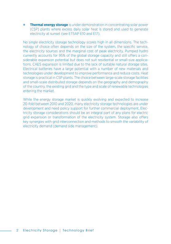
● Thermal energy storage is under demonstration in concentrating solar power (CSP) plants where excess daily solar heat is stored and used to generate electricity at sunset (see ETSAP E10 and E17).
No single electricity storage technology scores high in all dimensions. The tech-nology of choice often depends on the size of the system, the specifi c service, the electricity sources and the marginal cost of peak electricity. Pumped hydro currently accounts for 95% of the global storage capacity and still off ers a con-siderable expansion potential but does not suit residential or small-size applica-tions. CAES expansion is limited due to the lack of suitable natural storage sites. Electrical batteries have a large potential with a number of new materials and technologies under development to improve performance and reduce costs. Heat storage is practical in CSP plants. The choice between large-scale storage facilities and small-scale distributed storage depends on the geography and demography of the country, the existing grid and the type and scale of renewable technologies entering the market.
While the energy storage market is quickly evolving and expected to increase 20-fold between 2010 and 2020, many electricity storage technologies are under development and need policy support for further commercial deployment. Elec-tricity storage considerations should be an integral part of any plans for electric grid expansion or transformation of the electricity system. Storage also off ers key synergies with grid interconnection and methods to smooth the variability of electricity demand (demand side management).
12-30705_Electricity-Storage_Inhalt.indd 2 21.12.12 15:02

Electr icity Storage | Technology Br ief 3
Highlights � Process and Technology Status – Electricity storage is a challenging and
costly process as electricity can only be stored by conversion into other forms of energy (e.g. potential, thermal, chemical or magnetic energy). In today’s grids, electricity storage capacity is modest (about 110 GW power capacity on a global basis), and power generation varies continuously to meet demand fl uctuations and ensure grid voltage and frequency stability. More electricity storage could help ensure grid balance and reduce the need for costly peak-load capacity. Electricity storage can also support the grid integration of variable renewables (i.e. wind and solar power), the production of which depends on meteorological conditions and varies daily and season-ally. There is a variety of storage technologies based on various processes and suited to diff erent services (e.g. bulk storage and load-levelling, voltage and frequency regulation, renewable integration, back-up power). Major storage technologies include pumped hydro, compressed air energy storage (CAES), fl ywheels, supercapacitors, fl ow cells and rechargeable batteries (e.g. Li-ion batteries) and super-conducting magnet energy storage (SMES). Among these, pumped hydro is the only widely used technology (i.e. 100 GW world-wide) for large-scale electricity storage. Li-ion batteries dominate the market of energy storage for portable devices and are also the primary candidate for energy storage in electric vehicles and distributed renewable power. All other technologies are under demonstration or in a pre-commercial phase. Storage technologies also include electricity conversion into hydrogen via electrolysis (see ETSAP P11) and thermal energy storage in concentrating solar power (CSP) plants (see ETSAP E10 and E17). Electric utilities are also considering the storage potential of electric vehicles: overnight charging of batteries could off er a unique opportunity for distributed electricity storage at virtually no cost. The US Department of Energy estimates that two million vehicles could help accommodate up to 10 GW of wind power.
� Performance and Costs – Performance and costs of storage systems are to be assessed with respect to the service. For example, back-up power for uninterruptable power systems (UPS) requires immediate (i.e. within sec-onds) response and moderate power output and can usually bear high costs in return for high reliability. Grid voltage and frequency regulation require a response time from seconds to minutes and higher power output. Daily load-levelling requires extensive power to be available for hours, and the cost it can bear depends on the marginal price of peak-load electricity. Investment costs for storage equipment are highly variable as technologies are mostly in pre-commercial phases with little operating experience except for pumped hydro. Cost projections are also scarce or unavailable. Pumped hydro and CAES
12-30705_Electricity-Storage_Inhalt.indd 3 21.12.12 15:02

Electr icity Storage | Technology Br ief4
provide utility-size storage (i.e. up to GW-size power output for several hours) for both load-levelling and voltage/frequency regulation but are not suited to small-size distributed storage or back-up power for UPS. They are the cheap-est storage options per unit of energy, with investment costs largely depend-ent on plant site and size, i.e. USD 2000-4000/kW for pumped hydro and USD 800-1000/kW for large CAES (assuming cheap, natural underground storage). Flywheels can make available kW- to MW-size power output for a limited time (seconds to minutes) with very short response time. They can be used for UPS, frequency regulation and wind power support in small grids. Their cost is also sensitive to the size, ranging from USD 1000/kW for small, simple fl ywheels to USD 4000/kW for MW-size multi-wheel systems. Super-capacitors also off er very short response time and high power density. They could be used as instantaneous voltage compensators or in combination with battery storage. Vanadium redox fl ow cells off er power capacity from kW-size to MW-size. They can be used to support wind power generation at a cost of USD 3000-5000/kW with prospects for a rapid reduction to USD 2000/kW. Rechargeable batteries (e.g. traditional lead-acid batteries, NaS batteries and large Li-ion batteries) are the technology of choice for distributed storage (e.g. residential/commercial PV systems up to MW-size). They can also be used for frequency regulation and UPS. Among batteries, Li-ion cells off er the best energy density (up to 630 Wh/l), cycle effi ciency (90%) and durability, along with the lowest self-discharge (5-8% per month at 21°C). Small Li-ion batteries for portable devices are commercially available at relatively low prices, but batteries for power applications are still expensive. They cannot simply be scaled-up and need enhanced safety and reliability. However, high learning rates (30%) in portable applications and large research eff orts on batteries for electric vehicles and wind energy storage promise a rapid cost reduction to less than USD 1000/kW. SMES systems off er high effi ciency (>90%) and immediate response but are currently used in pilot projects or devices for other applications.
� Potential and Barriers – Energy storage technologies are quickly evolving since the share of renewable electricity is growing fast and there is an increas-ing need for storage capacity. Storing low-cost electricity (e.g. overnight) and selling it during peak-demand periods could soon become cost eff ective due to the increasing cost of peak electricity. Estimates suggest a global grid-tied storage market rising from USD 1.5 billion in 2010 to about USD 35 billion in 2020. Explorative simulations assuming high renewable energy share (IEA ETP 2008 Blue Scenario) suggest that in Western Europe a storage capacity of about 90 GW would be needed by 2050 to cope with net variations of 30% of then-current wind power capacity. On a global scale, the storage capacity needed to accommodate wind power variations by 2050 is estimated to be between 190 GW and 300 GW. Among storage technologies, pumped hydro
12-30705_Electricity-Storage_Inhalt.indd 4 21.12.12 15:02
Electr icity Storage | Technology Br ief 5
and CAES have a moderate expansion potential, a major barrier being the need for suitable installation sites. A strong market growth is anticipated for grid-tied Li-ion batteries (USD 6 billion by 2020, IHS estimates) in relation to the deployment of smart grids. Other storage technologies need more dem-onstration to enter the market. Policy measures are needed to support market uptake of electricity storage.
12-30705_Electricity-Storage_Inhalt.indd 5 21.12.12 15:02
Electr icity Storage | Technology Br ief6
Need for Electricity StorageElectricity can only be stored after conversion into other forms of energy (i.e. po-tential, mechanical, thermal, chemical, electrostatic or magnetic energy). In gen-eral, electricity storage (i.e. storing electricity when production exceeds demand and using it during peak-demand periods) is a challenging and costly process. In today’s power grids, electricity storage capacity is modest (about 110 GW on a global basis [1]), and power generation varies continuously to meet demand fl uc-tuations. A good supply-demand balance is not only essential to meet the demand but also ensures grid voltage and frequency stability and the overall reliability of the power system. More electricity storage could help balance the grid, reduce the need for costly peak-load capacity and operate base-load power plants1 effi ciently at full power. More importantly, electricity storage can facilitate the grid integra-tion of renewable power technologies, such as wind and solar, the production of which varies depending on meteorological conditions as well as daily and season-ally, with variations lasting for seconds to minutes to hours.
The reliable operation of today’s grids with high shares of renewables (e.g. Denmark, Spain) is mostly ensured by interconnection with adjacent grids, load-following and peak-load capacity, and control systems to ensure a good demand-supply balance2. This strategy allows more than a 20% share of wind electricity to be accommodated in the power grid with no major storage facilities. However, it could become insuffi cient if the share of variable renewables increases signifi -cantly in all regions. In particular, short-term (seconds to minutes) power output variations due to wind and solar power3 could aff ect the stability of the grid fre-
1 Power plants traditionally fall into three categories: base-load, peak, and load-following. Base-load power plants (coal, nuclear, large hydro) operate constantly at full power and stop only for mainte-nance. They have high capital costs but provide low-cost electricity and usually meet the lowest level of demand the utility experiences. Peak power plants (mostly gas-turbines starting in a few minutes) operate only during peak-demand periods, have low capital costs and generate relatively expensive electricity. Load-following power plants (typically hydro and steam turbines) are between the fi rst two. They usually run below their nominal output (spinning reserve), ready to adjust for demand fl uctuations. Power plants based on variable renewables (PV, CSP, wind power) do not fall into these categories. Their outputs vary minute to minute, day to day and depend on the meteorological condi-tions, the time of day and the seasons.
2 Other measures include demand-side management (e.g. incentives to users to shift electricity con-sumption during off -peak periods) and the use of electrical devices that work with variable voltage (e.g. 110–130V or 220–240V), as load variations can result in grid voltage variations.
3 PV power can be drastically reduced by clouds; wind turbines can go off -line in a matter of seconds during storms or be unavailable for hours due to lack of wind. Although the impact of these events may be smoothed when several distributed renewables are in operation, severe wind power drops (e.g. thousands of MW going off -line at a rate of several percentage points per minute) have already occurred (e.g. [22]).
12-30705_Electricity-Storage_Inhalt.indd 6 21.12.12 15:02

Electr icity Storage | Technology Br ief 7
quency, which falls when demand exceeds supply and rises when supply exceeds demand. Therefore, electricity storage is expected to become a key component of power systems with high renewable shares.
Technology Status and Performance There is a variety of electricity storage technologies for diff erent applications and services, e.g. bulk storage, peak-shaving (load-levelling), grid support (voltage and frequency regulation), grid integration of renewable sources, back-up power for uninterruptable power supply (UPS) and storage for residential PV systems. They are based on various processes to convert electricity into other forms of energy. This brief outlines major storage technologies except those involving electricity conversion into thermal energy and hydrogen, which are dealt with in ETSAP E17 and ETSAP P11, respectively. Depending on the specifi c technology, the performance of a storage system can be defi ned by the following parameters:
● Energy storage capacity (kWh) is the amount of energy that can be stored in the system4.
● Charge and discharge rates (kW) defi ne how fast energy can be charged/discharged5. For most technologies, the discharge rate can vary during opera-tion and is often higher than the charge rate.
● Response time (in seconds, minutes) is the time needed for the storage system to start providing energy on demand.
● Lifetime of a storage system is given as the number of cycles, years or stored/provided energy (kWh), depending on the specifi c technology.
● Effi ciency (or roundtrip effi ciency, %) is the ratio of energy discharged by the system to the energy needed to charge it at each cycle and accounts for energy lost in the storage cycle.
● Energy density (kWh/kg, kWh/m3, Wh/l) and power density (kW/kg and kW/m3) matter in applications where space is at a premium.
� Pumped Hydro – Pumped hydro is the most mature and widely used technol-ogy for large-scale energy storage. It accounts for 95% of the current storage capacity. Pumped hydro systems consist typically of two reservoirs located at diff erent elevations, a pump and a hydro-turbine or a reversible pump-turbine
4 For batteries working at a certain operating voltage V, energy storage capacity is given as Ah, with kWh=V × Ah/1000
5 (for batteries it is often given as amperes (A), with kW=V × A/1000.
12-30705_Electricity-Storage_Inhalt.indd 7 21.12.12 15:02
Electr icity Storage | Technology Br ief8
device (i.e. Francis turbine). During low-demand periods (usually at night), excess low-cost electricity is used to pump water from the lower reservoir to the upper one. During peak-load periods, the system generates power just like a conventional hydro-power plant (ETSAP E06). Pumped hydro systems based on artifi cial reservoirs can off er high power capacity (up to a few GW) for short periods (6–10h). Systems based on large, natural water sources and dams (often with no pumping device) are often used to provide daily and even seasonal storage (e.g. dry seasons) with power output of typically 200–400 MW. In general, pumped hydro systems can start operation and reach full power in a few minutes. They can be used as a capacity reserve, as well as for grid frequency and voltage stabilization6. Modern pumped hydro plants are equipped with variable-speed pump-turbine machines. When working as a turbine, they generate power with grid frequency synchronisation while in pumping mode they can work asynchronously with a variable speed. This enables grid frequency stabilization during pumping (overnight) by quickly changing the input power (automatic frequency control). The effi ciency of the pumped hydro systems (i.e. energy output to energy absorbed for pumping) is between 70% and 80%. This includes typical pump and turbine effi ciency of 92%, motor and generator effi ciencies of 98% and energy losses of typically 7% (93% effi ciency) in pumping and turbine operation. In order to increase the relatively low energy density7, pumped hydro systems need very large water reservoirs or large elevation variations between lower and upper reser-voirs. Their typical lifetime is over 30 years (50,000 cycles).
Pumped hydro storage was developed in Italy and Switzerland in the 1890s. The global installed capacity is currently about 104 GW (2008) in some 200 plants, of which 38 GW are in the EU, 25 GW in Japan and 22 GW in the United States [1]. An additional 20 GW are under construction and about 40 GW are under consideration [2, 3]. Some 40% of the existing systems have a capacity of between 100 and 400 MW while about 20% have more than 1 GW capacity. The largest plants with GW-size capacity include Bath County (2.8 GW) US, Guangdong (2.4 GW) China, Okutataragi (1.9 GW) Japan, Ludington (1.9 GW) US and Tianhuangping (1.8 GW) China. The Tianhuangping plant (8 million m3 water, 600m height, 80% effi ciency) could provide up to 13 GWh, about 2% of China’s daily electricity consumption.
� Compressed Air Energy Storage (CAES) – CAES systems use off -peak electricity to compress and store air into underground mines or caverns. Compressed air is then used in natural gas turbines (ETSAP E02) to gener-ate peak-load electricity. Usually simple-cycle gas turbines use almost two-
6 Pumped hydro can also provide reactive powerto the grid.
7 1 m3 water over 100m height gives 0.27kWh potential energy.
12-30705_Electricity-Storage_Inhalt.indd 8 21.12.12 15:02
Electr icity Storage | Technology Br ief 9
thirds of the input fuel to compress air prior to combustion (i.e. effi ciency of 37–38%). Using compressed air from CAES, the turbine can save up to 40% of the input fuel used to generate electricity, and the typical effi ciency (i.e. ratio of energy output to energy needed for compression) of a CAES with a simple-cycle gas turbine is about 50% [2]. This effi ciency can be increased using combined cycle gas turbines. CAES systems can come on line and react to power demand changes in about 15 minutes. Compressed air is stored at pressures between 45 and 70 bars into 500–800m-deep caverns. Relatively low-cost storage caverns can be obtained from natural salt deposits by in-jecting large amounts of water to dissolve the salt. However, the number of appropriate natural sites for CAES is rather limited, and the use of metal vessels for air storage is very expensive. At present, CAES systems in opera-tion include the 290-MW Huntorf plant in Germany (since 1978) and the 110 MW McIntosh plant in Alabama (since 1991). With two caverns of 150,000 m3, the Huntorf plant requires 60 MW for 12h for air compression and provides about 425 kg/s of compressed air (up to 70 bars) to generate up to 290 MW for a limited time. A few CAES projects are under development or under consideration worldwide, including three projects in the United States with capacities between 150 and 300 MW. Because air temperature increases during compression and the energy needed for compression increases with air temperature, air must be cooled during compression to reduce the com-pression energy and then re-heated prior to combustion. Therefore, CAES ef-fi ciency could be improved either using the fl ue gas for air preheating (before combustion) or even storing the heat extracted from air cooling and re-using it for air pre-heating (adiabatic CAES). The fi rst option has been adopted in the US McIntosh plant to raise the plant effi ciency up to 55%. Adiabatic CAES is still under development. The fi rst adiabatic CAES system (200MW) has been planned in Germany for 2013 [4].
� Flywheels – Flywheel systems store electrical energy as kinetic (rotational) energy. During charging, the fl ywheel rotation speed increases up to 30,000-50,000 rpm [2, 5], driven by a motor-generator. During discharging, the fl ywheel rotation drives the generator to produce electricity. To minimize the energy loss, friction must be minimized by operating the fl ywheel in a vacuum and using magnetic bearing instead of mechanical bearing. This considerably increases the cost of the device but enables storage effi ciency of more than 85% [6]. The rotational energy depends on fl ywheel diameter; therefore, larger fl ywheels enable higher energy storage. Proper materials (e.g. Ti-alloys and glass/carbon fi bre-reinforced plastics) are needed to resist the centrifugal force. Compared with other forms of electricity storage, fl ywheels off er a high power output for a short time, long lifetime (105 cycles), little or no mainte-nance and high energy density (100–130 Wh/kg) [5, 7] – though commercial systems off er much lower values [8]. Flywheels can be broadly divided into
12-30705_Electricity-Storage_Inhalt.indd 9 21.12.12 15:02

Electr icity Storage | Technology Br ief10
three categories depending on power and time service: a few kW for a few hours’ service; a few hundred kW for 15 seconds to minutes’ service; and 600–1200 kW for time service of 10-15 seconds [2]. Flywheels can be started and charged in a time span of some minutes. At present, commercial fl ywheels are mostly used to provide back-up power to uninterruptible power systems (UPS), e.g. data centres, medical devices. In comparison with lead batteries, fl ywheels for UPS need little maintenance, replacement only every few years and higher effi ciency. Flywheels can be used in the transport sector to help regulate railway line voltage and to recover energy from vehicle regenerative braking (trial projects in London, Lyon, Tokyo and New York [9]). Applications to mitigate variations of wind power from individual wind turbines and wind farms in small grids have also been successfully demonstrated: fl ywheels in combination with low-load diesel engines (LLD) have been used to maximize the wind power generation (Power Corporation, Australia). MW-size fl ywheel systems are also used to stabilize the power output. One of the largest fl y-wheel systems has been working in Japan since 1985 with more than 10,000 charge-discharge cycles. It consists of six disks (6.6m diameter, 107 tonnes each), which are charged in six minutes, absorbing 19 MW and providing up to 160 MW during 30s discharge. Okinawa Electric Power Company and Toshiba have also developed and installed a 23 MW fl ywheel system for frequency control in the Okinawa power grid. Beacon Power has developed fl ywheels for frequency regulation (100 kW each for 15 minute discharge) and a multi-fl y-wheel system for frequency regulation with a 20 MW capacity and a 15 minute discharge time, which is also able to compensate for short-term variations of wind power output. The system is in operation since 2011 at the Stephentown energy storage plant, New York [10]. Eff orts to improve fl ywheel effi ciency include the use of superconducting magnetic levitation.
� Supercapacitors – Supercapacitors (also referred to as electrochemical dou-ble-layer capacitors or ultra-capacitors) are high-capacitance electrochemical condensers. They are based on a thin, layered solid-liquid interface created by special, high-surface (1000 m2/g) carbon electrodes and electrolytes. Super- capacitors enable energy storage with higher power density (up to 6–8 kW/kg) and lower specifi c energy (e.g 30 Wh/kg8) in comparison with Li-ion batteries (100-250 Wh/kg). They can discharge their energy content in a short time, depending inversely on the output power (e.g. 10 kW for sec-onds or 1kW for one minute), and off er long lifetimes (e.g. 100,000 cycles). Marketed for the fi rst time in 1978 to provide back-up power for computer memory, supercapacitors were then used in a variety of commercial applica-tions, such as low-voltage electronics, emergency power and energy storage with short charging/discharging times. Due to the short response time and
8 Higher values of 85 Wh/kg achieved in laboratory
12-30705_Electricity-Storage_Inhalt.indd 10 21.12.12 15:02
Electr icity Storage | Technology Br ief 11
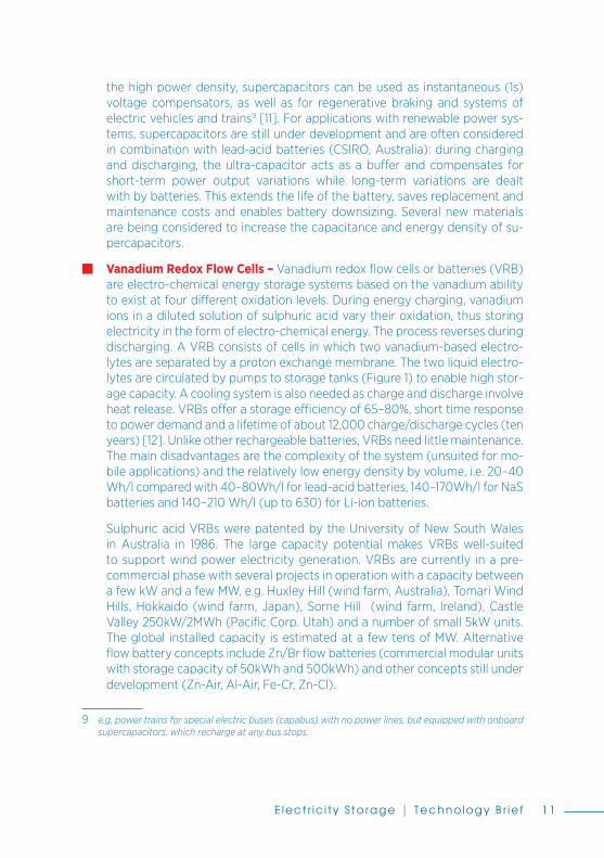
the high power density, supercapacitors can be used as instantaneous (1s) voltage compensators, as well as for regenerative braking and systems of electric vehicles and trains9 [11]. For applications with renewable power sys-tems, supercapacitors are still under development and are often considered in combination with lead-acid batteries (CSIRO, Australia): during charging and discharging, the ultra-capacitor acts as a buff er and compensates for short-term power output variations while long-term variations are dealt with by batteries. This extends the life of the battery, saves replacement and maintenance costs and enables battery downsizing. Several new materials are being considered to increase the capacitance and energy density of su-percapacitors.
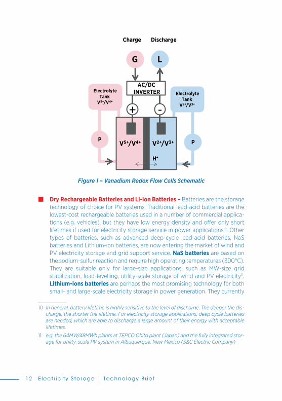
� Vanadium Redox Flow Cells – Vanadium redox fl ow cells or batteries (VRB) are electro-chemical energy storage systems based on the vanadium ability to exist at four diff erent oxidation levels. During energy charging, vanadium ions in a diluted solution of sulphuric acid vary their oxidation, thus storing electricity in the form of electro-chemical energy. The process reverses during discharging. A VRB consists of cells in which two vanadium-based electro-lytes are separated by a proton exchange membrane. The two liquid electro-lytes are circulated by pumps to storage tanks (Figure 1) to enable high stor-age capacity. A cooling system is also needed as charge and discharge involve heat release. VRBs off er a storage effi ciency of 65–80%, short time response to power demand and a lifetime of about 12,000 charge/discharge cycles (ten years) [12]. Unlike other rechargeable batteries, VRBs need little maintenance. The main disadvantages are the complexity of the system (unsuited for mo-bile applications) and the relatively low energy density by volume, i.e. 20–40 Wh/l compared with 40–80Wh/l for lead-acid batteries, 140–170Wh/l for NaS batteries and 140–210 Wh/l (up to 630) for Li-ion batteries.
Sulphuric acid VRBs were patented by the University of New South Wales in Australia in 1986. The large capacity potential makes VRBs well-suited to support wind power electricity generation. VRBs are currently in a pre-commercial phase with several projects in operation with a capacity between a few kW and a few MW, e.g. Huxley Hill (wind farm, Australia), Tomari Wind Hills, Hokkaido (wind farm, Japan), Sorne Hill (wind farm, Ireland), Castle Valley 250kW/2MWh (Pacifi c Corp. Utah) and a number of small 5kW units. The global installed capacity is estimated at a few tens of MW. Alternative fl ow battery concepts include Zn/Br fl ow batteries (commercial modular units with storage capacity of 50kWh and 500kWh) and other concepts still under development (Zn-Air, Al-Air, Fe-Cr, Zn-Cl).
9 e.g. power trains for special electric buses (capabus) with no power lines, but equipped with onboard supercapacitors, which recharge at any bus stops.
12-30705_Electricity-Storage_Inhalt.indd 11 21.12.12 15:02
Electr icity Storage | Technology Br ief12
� Dry Rechargeable Batteries and Li-ion Batteries – Batteries are the storage technology of choice for PV systems. Traditional lead-acid batteries are the lowest-cost rechargeable batteries used in a number of commercial applica-tions (e.g. vehicles), but they have low energy density and off er only short lifetimes if used for electricity storage service in power applications10. Other types of batteries, such as advanced deep-cycle lead-acid batteries, NaS batteries and Lithium-ion batteries, are now entering the market of wind and PV electricity storage and grid support service. NaS batteries are based on the sodium-sulfur reaction and require high operating temperatures (300°C). They are suitable only for large-size applications, such as MW-size grid stabilization, load-levelling, utility-scale storage of wind and PV electricity11. Lithium-ions batteries are perhaps the most promising technology for both small- and large-scale electricity storage in power generation. They currently
10 In general, battery lifetime is highly sensitive to the level of discharge. The deeper the dis-charge, the shorter the lifetime. For electricity storage applications, deep cycle batteries are needed, which are able to discharge a large amount of their energy with acceptable lifetimes.
11 e.g. the 64MW/48MWh plants at TEPCO Ohito plant (Japan) and the fully integrated stor-age for utility-scale PV system in Albuquerque, New Mexico (S&C Electric Company)
V2+/V3+V5+/V4+
+ -
P P
ElectrolyteTank
V5+/V4+
ElectrolyteTank
V2+/V3+
G L
AC/DC INVERTER
Charge Discharge
H+
Figure 1 – Vanadium Redox Flow Cells Schematic
12-30705_Electricity-Storage_Inhalt.indd 12 21.12.12 15:02
Electr icity Storage | Technology Br ief 13
off er superior performance and dominate the market of mobile phones and laptops but need further development for application to power generation. Lithium-ion batteries are a family of rechargeable batteries in which lithium ions move from anode to cathode during discharge through a non-aqueous12 electrolyte (and back during charging)13. Materials, chemistry, performance, costs and safety features vary signifi cantly within the family. The cathode can be lithium cobalt oxide (LiCoO2), lithium-iron phosphate (polyanion) or lithium manganese oxide (spinel); the anode is made of carbon (graphite or special carbon-based materials); the electrolyte can be lithium salt (LiPF6, LiBF4 or LiClO4) in an organic solvent (ethylene-, dimethyl- and diethyl-car-bonate). Li-ion batteries were developed from 1970 onward with the contri-bution of several individuals and organizations. Their commercial production and performance have been increasing rapidly from 2003 onward. Compared to other rechargeable batteries for mobile applications (e.g. NiCd, NiMH), they off er the best energy density (125–250 Wh/kg, up to 250–63014 Wh/l), cycle effi ciency (90%) and durability (400–1200 cycles), along with high power density (230–340 W/kg, up to 1500 W/kg), lowest self-discharge (5–8% per month at 21°C, 15% at 40°C, 31% at 60°C) [14, 15, 16], and no memory eff ect15. Li-ion batteries can also operate in a wider range of temperatures. In com-parison, NiCd and NiMH batteries have a maximum energy density of 200 and 350 Wh/l and self-discharge rates of 10% and 30% per month at room temperature, respectively. However, Li-ion batteries’ applications to power generation require diff erent types of Li-ion batteries, signifi cantly lower costs and safer operation. Industry is currently in the process of improving capacity, power size, reliability and safety for applications to both electrical vehicles and power generation. A key issue relates to safety. The high energy density of Li-ion batteries, abnormal heating due to overcharging, possible short circuits due to lithium precipitation, heat produced at the anode and oxygen at the cathode can result in hazardous operation. In current portable devices, these issues have been solved by internal components and systems, (e.g. protection against over-voltage, over-current, over-temperature, over-charging and relief valves to avoid gas overpressure due to overcharging).
12 Pure lithium reacts vigorously with water; thus a non-aqueous sealed electrolyte is used to avoid contact with water.
13 Typical chemical reactions are as follows (charge/discharge): • Electrode (+): LiCoO2 Li1-xCoO2 + xLi+ + xe-
• Electrode (-): xLi+ + xe- + 6C LixC6
• Whole battery: LiCoO2+ C Li+ - xCoO2 + CLix14 Panasonic 2.85Ah18650 cell
15 Memory eff ect is a reduced discharge capacity when the battery is incompletely dis-charged and recharged.
12-30705_Electricity-Storage_Inhalt.indd 13 21.12.12 15:02
Electr icity Storage | Technology Br ief14
All these systems ensure safe operation but add volume and complexity and increase costs. Alternative materials and solutions are needed for automotive and power applications. For example, lithium-cobalt16 oxide can be replaced with lithium-metal phosphate (though at the cost of a lower capacity) and a number of novel approaches and materials (including nanomaterials) are being explored. These eff orts are expected to result soon in commercial products. Li-ion batteries could have a wide range of applications in power generation, including renewable electricity storage for both distributed and centralized installations, grid support and load leveling, as well as emergency and back-up power for UPS.
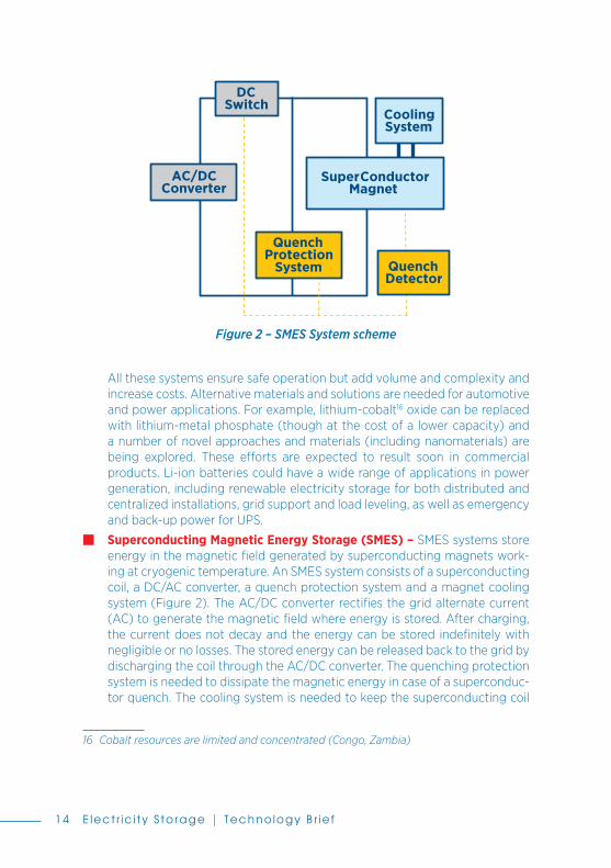
� Superconducting Magnetic Energy Storage (SMES) – SMES systems store energy in the magnetic fi eld generated by superconducting magnets work-ing at cryogenic temperature. An SMES system consists of a superconducting coil, a DC/AC converter, a quench protection system and a magnet cooling system (Figure 2). The AC/DC converter rectifi es the grid alternate current (AC) to generate the magnetic fi eld where energy is stored. After charging, the current does not decay and the energy can be stored indefi nitely with negligible or no losses. The stored energy can be released back to the grid by discharging the coil through the AC/DC converter. The quenching protection system is needed to dissipate the magnetic energy in case of a superconduc-tor quench. The cooling system is needed to keep the superconducting coil
16 Cobalt resources are limited and concentrated (Congo, Zambia)
Figure 2 – SMES System scheme
AC/DC Converter
CoolingSystem
QuenchProtection
System
DC Switch
QuenchDetector
Super ConductorMagnet
12-30705_Electricity-Storage_Inhalt.indd 14 21.12.12 15:02
Electr icity Storage | Technology Br ief 15
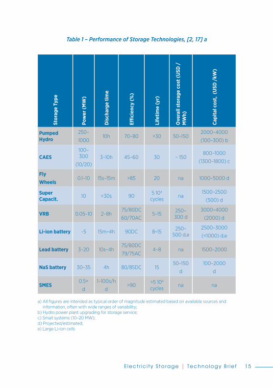
Table 1 – Performance of Storage Technologies, [2, 17] a
Stor
age
Type
Pow
er (M
W)
Dis
char
ge ti
me
Effi c
ienc
y (%
)
Life
time
(yr)
Ove
rall
stor
age
cost
(USD
/M
Wh)
Capi
tal c
ost,
(USD
/kW
)
Pumped Hydro
250–
100010h 70–80 >30 50–150
2000–4000
(100–300) b
CAES100–300
(10/20)3–10h 45–60 30 – 150
800–1000
(1300–1800) c
FlyWheels
0.1–10 15s–15m >85 20 na 1000–5000 d
Super Capacit. 10 <30s 90
5 104
cyclesna
1500–2500
(500) d
VRB 0.05–10 2–8h75/80DC
60/70AC5–15
250–300 d
3000–4000
(2000) d
Li-ion battery ~5 15m–4h 90DC 8–15250–
500 d,e2500–3000
(<1000) d,e
Lead battery 3–20 10s–4h75/80DC
79/75AC4–8 na 1500–2000
NaS battery 30–35 4h 80/85DC 1550–150
d
100–2000
d
SMES0.5+
d
1–100s/h
d>90
>5 104
cyclesna na
a) All fi gures are intended as typical order of magnitude estimated based on available sources and information, often with wide ranges of variability;
b) Hydro power plant upgrading for storage service; c) Small systems (10–20 MW); d) Projected/estimated; e) Large Li-ion cells
12-30705_Electricity-Storage_Inhalt.indd 15 21.12.12 15:02

Electr icity Storage | Technology Br ief16
Figure 3 – Typical power output and discharge time of electricity storage tech-nologies [2, 17]
High PowerS.Cap SMES
High PowerFlywheels
NiMH Batteries
NiCdBatteries
Lead Acid Batteries
Li-Ion Batteries
H. Energy S.Cap
CAES
NaSBatteries
Adv. Pb-Acid Batteries
PumpedHydro
UPS, powerquality Gridsupport & loadlevelling Bulk power mgt
1 kW 10 kW 100 kW 1 MW 10 MW 100 MW 1 GW
Seco
nds
Min
utes
Hou
rs
System Power
Dis
char
geTi
me
atR
ated
Pow
er
Flow Batteries, VRB, ZnCl, ZrBr, etc.
below the critical temperature (i.e. about 4K in the case of NbTi and Nb3Sn superconductors). SMES systems off er high storage effi ciency (>90%) [20] and high energy density with very short response time (close to zero). Power is available almost instantaneously. High power output can be provided for short time periods. Energy losses are associated to the AC/DC converter (2–3%) and to the superconductor refrigeration system. The basic SMES technology is currently available: small-scale superconducting magnets are used in commercial devices (e.g. magnetic resonance) while large-scale su-perconducting magnets are being developed for fusion power experiments and particle detectors.
The high cost of the superconductors is the primary barrier to commercial use of SMES for energy storage. Due to the energy needed for refrigeration, SMES is well-suited to short-term energy storage. Several demonstration SMES with power between 200 and 800 kW have been tested in Japan and the United States for distributed grid regulation and stabilization (D-SMES) and power-quality indus-trial voltage regulators.
Key parameters of storage systems (i.e. typical storage capacity, discharge time, effi ciency, lifetime and costs) are summarised in Table 1. Power output and dis-charge time are also provided in Figure 3. The overall performance of a storage system is to be assessed with respect to the required service.
12-30705_Electricity-Storage_Inhalt.indd 16 21.12.12 15:02

Electr icity Storage | Technology Br ief 17
Costs and Cost Projections In general, energy storage is economically competitive if the electricity marginal price is higher than the cost of storing and retrieving electricity, including the cost of energy lost in the process. Apart from pumped hydro, which is the only mature and commercial storage option, the investment and operation costs of electricity storage facilities are rather high and highly variable as technologies are still under demonstration or in pre-commercial phases, and there is neither large-scale pro-duction of components nor operation experience. Cost projections are also scarce or unavailable. With the exception of Li-ion batteries, which have experienced mass production for mobile applications, technology learning curves and cost reduction patterns must be extrapolated from other technologies. Consequently, the costs discussed below have to be considered as indicative estimates often with a wide range of variations.
Investment or capital costs of a storage technology can be given per unit of power capacity (USD /kW) or per unit of energy storage capacity (USD /kWh). Operat-ing costs are given per unit of power capacity per year (USD /kW-yr). The overall cost and the levelised cost of energy storage are given per unit of energy (USD /kWh) as the ratio of all costs incurred for storing the energy (capital, operation and energy costs, if any) to the total amount of energy stored in all storage cycles over the plant’s lifetime.
Pumped hydro is the cheapest option for large-scale electricity storage. The cur-rent capital cost of new pumped hydro facilities is estimated to range between USD 2000–4000/kW, with dam and civil infrastructure accounting for 60%, pump-turbine devices for 15% and other components and systems for the remain-ing 25% [2]. The cost is very sensitive to the site, and no cost reduction is expected from technology learning as pumped hydro is a mature technology. Upgrading existing dams with additional electricity generators to increase production fl ex-ibility is by far the cheapest option among energy storage technologies with costs as low as USD 100–300/kW [18]. The overall cost of pumped hydro energy storage is estimated at between USD 50 and USD 150 per MWh. The estimated capital cost for new CAES facilities using natural underground caverns is on the order of USD 800–1000/kW for capacities of 100-300 MW (assuming a cheap availability of natural underground storage sites) and USD 1500–1800/kW for small capacity (10–20 MW) [17]. The capital cost of CAES systems is also sensitive to the site. CAES systems with ground in-vessel storage are estimated to be three to fi ve times higher [2]. The overall cost of CAES storage is on the order of USD 150/MWh. Flywheels’ capital cost is also sensitive to size and applications. It ranges from less than USD 1000/kW for small, simple UPS systems [19] to USD 4000/kW for MW-size systems [17]. The prospective cost of very large (10 MW) systems
12-30705_Electricity-Storage_Inhalt.indd 17 21.12.12 15:02

Electr icity Storage | Technology Br ief18
is estimated at around USD 3000/kW. Supercapacitor cost is estimated to range between USD 1500 and USD 2500 per kW with a learning rate of 14-15% [2] based on the current production (the current value of supercapacitors’ global market in sectors other than energy storage is estimated to amount to a few hundred million dollars per year). This could enable signifi cant cost reductions (USD 500/kW) [17] in case of ample production. Vanadium fl ow cells are also projected to reduce their capital cost from the current level of USD 3000 to USD 4000 per kW [17] to about USD 2000/kW with a prospective overall storage cost of USD 250–300/MWh, depending of actual lifetime. Li-ion batteries for power applications are still expensive (up to USD 2500/kW) because of the need for new materials and technology, as well as overcharging protection and packaging to improve reliability and safety. However, experience curves for production of batteries for mobile applications show high learning rates (30%) [2]. In addition, a number of manufacturers are developing large Li-ion batteries for electric vehicles and wind energy storage. Thus, capital cost is declining quickly to less than USD 1000/kW. The prospective overall storage cost is set somewhere between USD 250 to 500 per MWh, depending on lifetimes. The capital cost of SMES systems is dominated by the superconductors while the operation cost is dominated by the cryogenic cooling system. Small superconducting systems for current commercial applica-tions (e.g. magnets for magnetic resonance medical devices) are available at an estimated cost between USD 700 and USD 2000 per kW [2, 17] while the cost of large superconducting magnets (e.g. for experimental nuclear fusion devices) is hardly scalable to energy storage systems. RASMES [20] suggests SMES capital costs between USD 200,000 and USD 500,000 for systems with energy storage capacity between 200 kWh and 1 MWh. SMES cost estimates are often based on the current.
Potential and Barriers Energy storage technologies and markets are quickly evolving as the share of renewable electricity grows and there is an increasing need for grid stabilization, load levelling and integration of variable renewables. The increasing cost of peak electricity will also make energy storage more attractive. The Pike Market Research fi rm estimates that the global energy storage market could rise from USD 1.5 bil-lion in 2010 to about USD 35 billion in 2020. The utility energy storage market is actually already growing as some regional energy policies require grid-tied stor-age. Explorative simulations [2] based on high renewable share scenarios (IEA ETP 2008 Blue Scenario [21]) suggest that, for net wind power variations between 5% and 30%, the need for storage capacity in Western Europe would be between
12-30705_Electricity-Storage_Inhalt.indd 18 21.12.12 15:02

Electr icity Storage | Technology Br ief 19
0 and 90 GW (i.e. no storage needed up to 5% net wind power variation). This is to be compared with recent measurements of wind power variations showing a net variability from 6% to 12% (over 10-15 minutes) in Western Europe and up to 24–35% in specifi c U.S. regions. In small regions, even net variations of 5% can have an impact on grid stability if interconnection and other smoothing eff ects are not available. On a global scale, simulations of 15% to 30% net wind power variations result in a need for storage capacity from 190 GW to 300 GW by 2050.
Among storage technologies, pumped hydro still has considerable expansion po-tential, the only barriers being the lack of suitable sites for installation and the local environmental impact. A large potential is associated with seawater pumped hy-dro, which off ers comparatively easier coastal location. A 30-MW demonstration plant with 136m head and 546,000m3 water storage is in operation in Okinawa (Japan). Seawater plants have been proposed in Ireland and in the United States. CAES expansion is also limited by the lack of suitable natural storage sites (e.g. caverns). However, signifi cant R&D eff orts focus on improving CAES effi ciency. The fi rst adiabatic CAES project (200MW) has been planned for construction in Germany [4]. Other investigations explore the use of advanced gas turbines (e.g. humid air turbine cycles) and compressors (with internal water atomisation cool-ers) to reduce compression energy.
A large market expansion potential is anticipated for Li-ion batteries. The market intelligence fi rm IHS iSupply estimates the grid-tied Li-ion battery market to reach USD 6 billion by 2020. This demand would be tied to the deployment of so-called smart grids in the current decade. While Li-ion batteries are still expensive, new types of low-cost batteries for large-scale electricity storage are under develop-ment (e.g. sodium-ion batteries). The cost decline of batteries and other storage technologies will make them appealing for power companies and householders to install more renewable capacity. Until then, policy measures are needed to support the energy storage market.
An important storage technology for low-cost (night) electricity is the conversion into hydrogen via electrolysis (see ETSAP P11). This option has been thoroughly explored in the past and was basically declined due to the low effi ciency of the electricity-hydrogen-electricity cycle and the high cost of hydrogen storage. At present, some utilities are reconsidering the process due to the increased effi cien-cy (more than 75%) of electrolysers and the possible conversion of hydrogen into methane (methanation) with CO2 absorption. This process is under consideration as a storage option for wind power. It is also the only process which could provide distributed seasonal electricity storage. Also important is the energy storage in concentrating solar power (CSP) where solar heat is stored in molten salt and used when sunlight is not available to generate fully dispatchable renewable electricity
12-30705_Electricity-Storage_Inhalt.indd 19 21.12.12 15:02
Electr icity Storage | Technology Br ief20
(see ETSAP E10 and E17). These plants already in operation can reach up to 15h storage capacity (e.g. 19 MW Torresol plant, Gemasolar, Spain), thus providing energy 24 hours a day, the same as conventional base-load power plants. CSP plants with heat storage also off er the opportunity to store energy from other variable renewables, thus representing an important tool for the grid integration of variable wind and PV power.
Electric utilities are also considering potential electricity storage in the batteries of electric vehicles: charging the batteries of electric vehicles overnight would of-fer a unique opportunity for distributed electricity storage with virtually no cost and could also contribute to emission reductions in the transport sector. A study by Pacifi c Northwest National Laboratory for the U.S. Department of Energy esti-mates that two million electric vehicles with a 33-mile electric range could provide enough grid stabilisation to accommodate some 10 GW of wind energy.
References and Further Information1. International Energy Statistics, 2010 – U.S. Energy Information Administration,
www.eia.gov; http://205.254.135.7/cfapps/ipdbproject/IEDIndex3.cfm.
2. IEA 2009 - Prospects for Large-Scale Energy Storage in Decarbonised Power Grids, International Energy Agency, Paris
3. Mc Coy Power Report 2008.
4. German AACAES project information, http://www.bine.info/pdf/publikation/projekt0507englinternetx.pdf.
5. Castelvecchi, D., 2007 - Spinning into control, Science News vol. 171, pp. 312–313.
6. Beacon Power - Frequency Regulation and Flywheels, Beacon Power Corporation Fact sheet, Accessed July 11, 2011.
7. Next-generation Flywheel Energy Storage“. Product Design & Development. http://www.pddnet.com/article-next-gen-of-fl ywheel-energy-storage/.
8. Rosseta Technik GmbH, Flywheel Energy Storage Model T4, Accessed February 4, 2010.
9. Railway Gazette International 2009 – New York orders fl ywheel energy storage, http://www.railwaygazette.com/nc/news/single-view/view/new-york-orders-fl y-wheel-energy-storage.html.
12-30705_Electricity-Storage_Inhalt.indd 20 21.12.12 15:02

Electr icity Storage | Technology Br ief 21
10. Beacon Power – Flywheel Plant in Stephentown Reaches Full 20 MW Capacity, Beacon Power Corporation Fact sheet.
11. U.S. DOE 2009 – Ultra capacitors, Offi ce of Energy Effi ciency and Renewable Energy.
12. http://www.vrb.unsw.edu.au;http://www.sciencedaily.com/releases/2009/10/091012135506.htm.
13. Graphene super capacitor breaks storage record. physicsworld.com. Accessed 13 Sep-tember 2011.
14. Rechargeable Li-Ion OEM Battery Products. Panasonic.com. http://www.panasonic.com/industrial/batteries-oem/oem/lithium-ion.aspx. 2010-04-23.
15. Panasonic Develops New Higher-Capacity Li-Ion Cells; http://www.greencarcongress.com/2009/12/panasonic-20091225.html. 2011-01-31.
16. Valøen & Shoesmith (2007). The eff ect of PHEV and HEV duty cycles on battery and battery pack performance (PDF). 2007 Plug-in Highway Electric Vehicle Conference: Proceedings. 2010-06-11.
17. EPRI 2009 - Rastler Dan, Overview of energy storage options for the electric enterprise, Electric Power Research Institute 2009.
18. U.S. DOI -Bureau of Reclamation, Hydroelectric Power, July 2005 http://www.usbr.gov/power/edu/pamphlet.pdf].
19. http://www.claverton-energy.com/active-power-article-fl ywheel-energy-storage.htm.
20. Research Association of Superconducting Magnetic Energy Storage, RASMES, http://www.rasmes.com/.
21. IEA 2008 – Energy Technology Perspectives 2008, International Energy Agency OECD/IEA, Paris.
22. EON 2005 – Wind Report 2005, EON Netz Gmbh, http://www.countryguardian.net/EON_Netz_Windreport2005_eng.pdf.
12-30705_Electricity-Storage_Inhalt.indd 21 21.12.12 15:02

Electr icity Storage | Technology Br ief22
Tabl
e 2
– Su
mm
ary
Tabl
e –
Key
Dat
a an
d Fi
gure
s fo
r Ele
ctric
ity S
toar
ge T
echn
olog
ies
Tech
nica
l Pe
rfor
man
ceTy
pica
l cur
rent
inte
rnat
iona
l val
ues
and
rang
es
Tech
nolo
gy
Varia
nts
Pum
ped
hydr
oC
AES
Hig
h po
wer
Flyw
heel
sSu
per
-ca
paci
tors
VR
B
fl ow
cel
lsLi
-ions
ba
tter
y SM
ES
Ener
gy in
put/
outp
utEl
ectr
icity
/Ele
ctric
ity
Serv
ices
, ap
plic
atio
ns
bulk
sto
rage
,lo
ad le
velli
ng,
f/v
regu
latio
n,re
new
able
s in
tegr
atio
n
bulk
sto
rage
,lo
ad le
velli
ng,
f/v
regu
latio
n,re
new
able
s in
te-
grat
ion
dist
r. st
orag
e,
UPS
bac
k-up
.lo
ad le
velli
ng,
rene
wab
les
inte
-gr
atio
n
dist
r. st
orag
e,
UPS
bac
kup,
v re
gula
tion,
auto
mot
ive
dist
r. st
orag
e,lo
ad le
velli
ng,
rene
wab
les
inte
-gr
atio
n
dist
r. st
orag
e,lo
ad le
velli
ng,
ren.
inte
grat
.,po
rtab
le p
ower
auto
mot
ive
dist
r. st
orag
e,lo
ad le
velli
ng,
f reg
ulat
ion
rene
wab
les
inte
-gr
atio
n
Stat
us
com
mer
cial
com
mer
cial
pre-
com
mer
cial
R&
Dpr
e-co
mm
pre-
com
mer
cial
pre-
com
mer
cial
R&
Dde
mo
Typi
cal p
ower
ou
tput
, MW
250
-10
00
100
-30
0
(10
-20
)0
.01-
100
.1-10
0.0
1-10
0.1-
5 (<
10)
0.1-
10+
Stor
age
capa
city
, kW
hna
na1-
25na
20-5
05-
10na
Ener
gy e
ffi ci
ency
, %
70-8
045
-60
> 85
9075
/80
DC
65/
70A
C90
DC
>90
Life
time,
yr
(cyc
les)
>30
>5E4
30 >1E4
20
(5E4
-1E5
)na
(5E4
) 5-
15/2
0
(1E4
)8-
15(1
-3E3
)na
(5E4
)
Res
pons
e tim
ese
c. to
min
.m
in.
sec.
sec.
shor
tse
c.Im
med
iate
Cha
rge
time
seve
ral h
rshr
s15
min
sec
nam
in to
hrs
shor
t
12-30705_Electricity-Storage_Inhalt.indd 22 21.12.12 15:02

Electr icity Storage | Technology Br ief 23
Dis
char
ge ti
me
seve
ral h
rshr
sse
c. to
min
se
c.
2-8
hrs
min
to h
rs1-
100
s (h
rs)
Ener
gy d
ensi
ty,
Wh/
llo
wlo
whi
ghhi
gh20
-40
(lo
w)
140
-630
a(h
igh)
Spec
ifi c
ener
gy,
Wh/
kglo
wlo
whi
ghna
low
125-
250
hi
gh
a) L
i-ion
bes
t per
form
ance
to b
e co
mpa
red
to N
aS (
140
-170
), le
ad-a
cid
(40
-80
); po
rtab
le N
iCd
(20
0)
and
NiM
H (
350
)
Cos
ts
Typi
cal c
urre
nt in
tern
atio
nal v
alue
s an
d ra
nges
(20
10 U
SD, 1
€ =
1.3
USD
)
Inve
stm
ent c
ost,
USD
/kW
20
00
-40
00
(1
00
-30
0)
a80
0-1
00
0(1
300
-180
0)
b20
00
-50
00
150
0-2
500
200
0-4
00
0up
to 3
00
0 c
(10
00
) d
700
-20
00
?
Inve
stm
ent c
ost,
USD
/kW
hcap
100
-250
50-1
5015
00
-30
00
na35
0-8
00
500
-150
0(5
00
-20
00
)
Ove
rall
stor
age
cost
, USD
/M
Wh
50-1
5015
0na
na25
0-3
00
250
-50
0na
Lear
ning
rate
, %no
neno
nena
15na
30na
Proj
ecte
d in
vest
-m
ent c
ost,
USD
/kW
20
00
-40
00
800
-10
00
na~
500
150
0-3
00
0<1
00
0na
Mar
ket p
rosp
ect
estim
ates
Som
e U
SD 3
5 bi
llion
glo
bal m
arke
t by
2020
; bet
wee
n 20
0 a
nd 3
00
GW
sto
rage
cap
acity
nee
ded
by 2
050
, in
high
-sha
re
rene
wab
le s
cena
rios
a) In
vest
men
t cos
t for
upg
radi
ng e
xist
ing
hydr
o-pl
ants
to th
e st
orag
e se
rvic
e;
b) in
vest
men
t cos
t of s
mal
l (10
–20
MW
) C
AES
sys
tem
s ;
c) p
ower
sto
rage
Li-i
on c
ells
; d)
fast
ong
oing
dec
line
to U
SD 10
00/
kW.
12-30705_Electricity-Storage_Inhalt.indd 23 21.12.12 15:02

12-30705_Electricity-Storage_Inhalt.indd 24 21.12.12 15:02

DisclaimerThe designations employed and the presentation of materials herein do not imply the expression of any opinion whatsoever on the part of the Sec-retariat of the International Renewable Energy Agency concerning the le-gal status of any country, territory, city or area or of its authorities, or con-cerning the delimitation of its frontiers or boundaries. The term “country” as used in this material also refers, as appropriate, to territories or areas.

Please send comments to
Giorgio Simbolotti ([email protected]) andRuud Kempener ([email protected]), Authors, and toGiorgio Simbolotti ([email protected]), Giancarlo Tosato ([email protected]) andDolf Gielen ([email protected]), Project Coordinators