IPSO F~~TO .' A~·· - COSMAC ELF · MEMBERSHIP CO-ORDINATOR Blair Gerrish 2110 Prospect St., Apt....
34
• IPSO /w,·: r:» .' Ot- PEl':) T f/v r= i\' T Ens ., .,-_ " TABLE OF CONTENTS Issue #13 September, 1979 PAGE • 1979-1980 A.C.E. Executive ••••••••••••••••••••••• 2 Editorial Comments •••••.•.•.•••••••••••••••.••.•. 3 Full Colour Display ••••••••••••••••••••••••• 4 Cassette 'File Counter' System ••••••••••••••••..• 7 Letters •••••••••••••••••••• •••••••••••• •••• 11,24 8-Level Interrupts ••••••••••••••••••••••••• 13 Tic-tac-toe Program for two players •••.••••••.•• 14 ·More Power to the El f ••••••••••••••••••••••••••• 17 Errata ••••.•••••••••••••••••••••••••••••••••• 21,26 Items for Sale •••.••.••••••••••••••••••• · •••••.•• 21 Machine-language Puzzler ••••• •••••••••••••••••. 23 Future Meeting Schedule ••••••••••••••••••••••••• 23 Super Graphics Control for the Elf •••••••••••••• 24 An application for memory-mapped 1/0 •••••••••••• 25 Ipso Facto Topical Index (Issues 1-6) ••••••••••• 27 Facto Topical Index (Issues 7-12) •••••••••• Renewal Form ••••••••••••••••••••••••• 34 > Information furnished bv IPSO FACTO is believed to be accurate and reliable. "However, no responsibility is assumed by IPSO FACTO or Association of Computer Expzrimenters for its use; nor for any infringements of patents or other rif,hts of third parties which may result its use. • -Send News.Letter correspondence to: Berni e lviurphy 102 McCrany Street, 'Oakville, Ontario Canada L6H lH6
-
Upload
phungkhanh -
Category
Documents
-
view
215 -
download
0
Transcript of IPSO F~~TO .' A~·· - COSMAC ELF · MEMBERSHIP CO-ORDINATOR Blair Gerrish 2110 Prospect St., Apt....

•IPSO F~~TO
·/w,·: r:»
.' A~··:
Ot-
~f PEl':) T f/v r= i\' T Ens., .,-_ 1~_Zl "
TABLE OF CONTENTS
Issue #13September, 1979
PAGE
•1979-1980 A.C.E. Executive ••••••••••••••••••••••• 2Editorial Comments •••••.•.•.•••••••••••••••.••.•. 318~2 Full Colour Display••••••••••••••••••••••••• 4Cassette 'File Counter' System ••••••••••••••••..• 7Letters •••••••••••••••••••• ~ •••••••••••• ~ •••• 11,2418~2 8-Level Interrupts ••••••••••••••••••••••••• 13Tic-tac-toe Program for two players •••.••••••.•• 14·More Power to the El f ••••••••••••••••••••••••••• 17Errata ••••.•••••••••••••••••••••••••••••••••• 21,26Items for Sale •••.••.••••••••••••••••••• ·•••••.•• 21Machine-language Puzzler ••••• ~ •••••••••••••••••. 23Future Meeting Schedule ••••••••••••••••••••••••• 23Super Graphics Control for the Elf •••••••••••••• 24An application for memory-mapped 1/0 •••••••••••• 25Ipso Facto Topical Index (Issues 1-6) ••••••••••• 27~pso Facto Topical Index (Issues 7-12) •••••••••• 3~
~~embership Renewal Form ••••••••••••••••••••••••• 34>
Information furnished bv IPSO FACTO is believed to beaccurate and reliable. "However, no responsibility isassumed by IPSO FACTO or th~ Association of ComputerExpzrimenters for its use; nor for any infringementsof patents or other rif,hts of third parties which mayresult f~om its use.
•-Send News.Letter correspondence to: Berni e lviurphy
102 McCrany Street,'Oakville, OntarioCanada L6H lH6

PAGE: 2
1979-1980 ACE EXECUTIVE COMMITTEE
PRESIDENT Edwa rd F1eet 5 Wells St.Toron to, ONT., M5R IN8416-925-5740 •
PAST PRESIDENT
TREASURER
ASSOCIATE EDITOR
Ken Bev is 220 Cherry Post Rd.Toronto, ONT., L5A 1H9416-277-2495
Mike Franklin 24 Duby Rd,Acton, ONT., L7J 2P1519-853-3421
Ear1 e La ycoc k ,2772 Ho 11 ing ton Cres. ,Mississauga, ONT, L5K 1E7416-823-1345
Bernie Murphy 102 McCraney St.,Oakville, ONT., L6H 1H6416-845-1630
ASSOCIATE EDITOR
ASSOCIATE EDITOR
CONSULTING EDITOR
Vic Kushnir
Bob Silcox
2640 Barnstone Cr.,Mississauga, ONT., L5K 2C1416-822-6505
562 Forestwood Cr.,Burlington, ONT., L7L 4K3416-681-2848
•DRAFTING J. Myszkowski 99 Augusta St.,Ham il ton, ONT.416-529-0250
MEMBERSHIP CO-ORDINATOR Blair Gerrish 2110 Prospect St., Apt. 3,Bur 1 i ng to n, On t ., L7R 1Y9416-634-0268
TRAINING CO-ORDINATOR Rod Dore 660 Oxford Rd., Unit 32,Burlington, ONT., L7N 1Y8416-681-2456
HARDWARE CO-ORDINATOR Fred Feaver 105 Townsend Ave.,Burlington, ONT., L7T 1Y8416-637-2513
PROGRAM CO-ORDINATOR Fred P1uthero 1013 Upper Wellington St.,Hamilton, ONT., L9A 3S4416-389-4070
PUBLISHING COMMITTEE Dennis Mi1don 44 Wi1dewood Ave.,Hamilton, ONT., L8T 1X3416-385-0798
John Hanson 955 Harvey Place,Burlington, ONT., L7T 3E9416-637-1076
•

EDITORIAL COMMENTSPAGE: 3
•
•
".
•
Since this is the first issue of the new season, there area number of points to cover •
First, as you may have noticed on the list of the newexecutive, the position of 'editor' has changed to consist of agroup of 'associate editors', it being hoped that in this way wewill be able to maintain the high quality of work provided by ourpredecessors, while at the same time dividing up the fairly largeamount of work involved in this undertaking.
A second point relates to the physical appearance andformat of the newsletter. We have been able to make use of aword-processing system in the preparation of some of the articles inthis issue (some of issue #12 was also prepared this way), and thisshould not only contribute to a more professional appearance, butmore importantly, the newsletter will be easier to read.
One aspect of this appearance change is the use of a newlogo on the cover page of the newletter. We would like to thankAllan Jackson for sending it in. Although too late for the T-shirtcontest, it seemed a shame to waste such an excellent effort. Toquote the designer: "The logo is stacked like an indigenous Canadiantotem pole, and reads almost the same upside down".
ARTICLE SUBMISSIONS
We can always use lots of articles, whether software orhardware 9riented, and whether they are on a highly technical orfairly "eJementary level. If anything, it is the elementary-levelar t IcLas which are in the shortest supply, and it is often thesewhi~h ~re of the most use to the largest number of readers. Eventhough a lot of our members are highly skilled technically, suchskills tend to be fairly specialized, and so, for instance, a realhardware 'whiz' may find good instructional articles on machinelanguage, or assembly language to be quite useful. Similarly, thosewith good programming backgrounds will appreciate good explanatoryarticles about hardware subject-matter.
We" appreciate getting whatever you can send in, in whateverform you can manage to write it up. However, you can make our jobmuch easier (and are likely to see your article in print at anearlier point) if you could manage to send articles to us incamera-ready form. By 'camera-ready' we mean typed, single-space,with a reasonably dark ribbon. Diagrams should be as large aspossible --- we can always photo-reduce them. Again, if you do nothave the facilities to type up submissions, then by all means sendus what you have in whatever form is easiest for you.
Enough for now --- we look forward, as you do, to anothergood year for A.C.E., and hope to keep providing the best 1802newsletter in the universe.)
NOTE: This issue is being sent only to those who haverenewed their membership for the coming year. Therefore, receiptof this issue will constitute acknowledgment of your renewal •
)

1802 FULL COLOUR DISPLAY
PAGE: 4
by: John Myszkowski99 Aug usta StHAMILTON,· Ont , , Canada
•
•Are you one of the unfortunate people that built himself (or
even herself) an affordable microcomputer (namely the ELF, SuperELF,ELF II, the TEC-1802 or even the VIP) and then realized that youcannot afford a decent.alphanumeric display for it? Well, now youcan rejoic~, because finally everybody is making ASCII Videodisplays for the ELFs and VIPs, and even TECs will soon have one.That is just great and fantastic--but expensive. "So I'll make myown" you say, but can't really decide which circuit to use (thereare quite a few of them). There were a couple of good ones in IPSOFACTO; but you prefer something even simpler than those two. Wellagain, you're in luck. Thanks to growing (or is it shrinking?)technology, we finally have an IC that does practically everythingthat is expected of most video terminals. This chip is called theMCM6847 VDG ("VIDEO DISPLAY GENERATOR" for short) and is made byMotorola Semiconductor Division. It can display 32 characters in 16lines in the alphanumeric mode, or up to 256 (horizontal) by 192(vertical) dots in full graphic mode (using up to 6K bytes ofrefresh memory), or it can mix ASCII characters and graphic dots atthe same time and on the same screen. It can do all that, plus itcan display up to eight colours. The 6847 chip can be obtainedthrough any distributor that handles Motorola parts, for about $20.Motorola is also selling an RF modulator chip which is madeespecially for the 6847 (but can be used with other video displaygenerators) and contains an on chip oscillator. This chip is theMCl372 COLOUR TV VIDEO MODULATOR, it costs about $3. The VDG(6847)was designed with the MC6800 microprocessor in mind, but it isactually very easy to interface to other systems.
To make it work with the 1802 microprocessor only a handfull ofIC's are needed. The "VDU for the 1802" is a complete video displayboard for the 1802 based systems and it uses the 6847 chip. Thecomplete minimum system (32x16 lines ASCII and 128H x 64V dotsgraphics) uses only sixteen chips and that includes all the buffersand refresh memory (which is like an extra lK bytes of fullyaccessible memory). This refresh memory can be expanded up to 6K,to give the board full graphics capability of 256xl92 dots. Thisboard can do graphics that will beat the 1861 chip graphics by amile because of the 8 colours and 4 luminance levels of each pixelnot to mention the ASCII display.
To begin with, the VDG IC addresses up to 6K of refresh memory,which also has to be accessed by the microprocessor to deposit orretrieve data. To accomplish this we have to do a few things. First,decode the address buss, so that the CPU will be able to access atleast 512 bytes (for the 32xl6 ASCII display) of memory, andpossibly more if it is desirable. Second, connect the VDG addresslines and the CPU address bus to the memory address, in such a waythat' neither one will interfere with the other when both are workingat the same time. This is done by "multiplexing" the two addre~
busses. To allow the CPU to access the refresh memory, the MS(memory select) line on the VDG is pulled low, which in turn forces
•
•

Rf.,.-e
2.4O.A
te'-BI 2'02 I~"
(011. u,~ ~':l1t4 zc's)re, I MC'84-7 YD~
C",pu :l1,~Ar"fIU,ltAfIl(
fI'..,Jl1 M"r"",,, ..,,)TruI," "'0" -Q ...J.".I.r.l
swilol..
('2.n 4042. -.flt.~ I.I-J,(f~.'S" 40/t{ -o...J NIp/Nt
·",,~t .'(.11 Me ';jlZ ·/(F "''pI/un.Iell -401' 0...." N4Nt1r-'r~c;.. 4016 /JAN&,~.Jc
~C:20 4041 HeJl I'W6I.T6~SI4f(~~
CI',' 40/i'o H,,, " ..fryJr.4L 3.S"SMllz
.}- If .,.r;.'l. d.,1eo
'-3~,.'~.r ....~.. eyI.
II I.If
p,."r,,1 PIIRTS LIST
~
\1
-11 IS4,t $oil!
~_ 55~n .
2 ..-i---",'
...1- i
-=- f-3~,.r
-""
-:J C't1C 11..~s!,!I,
L;,J;'".12 ~/s
I,a,rIt (iii'
, M"M1
tJ G) AoE:~
~'-;"!I:'
~ A,ts:=MS
-!- -n&
1
"'1,.1.17~'h 121.\I;({i'111~h IIIH4·1'1"" -
..,'-.
401'f(ffi
--- ~ . '++
,UI
~
vee
-v
." 11> If 111110 ,.
-----
OQ -_.• _-_._---------
~
.:»If
I It
.---. . . .r::-..~z
• 13 14 IS
A-(... ''''I iI L @\
IC 2'/%2
~_4
~E!I II" 'II~
Jq--....--
~o
Ml\O~
SCHOOLTITLE VDU. FOR THf 1802.
DR BY- JOHN MT.5ZKOW.sK'DATE - 4- MAY tlf7'
.SCALE- ,;: ........., +e r",z'
FORM-CHK-DWG NO-)-.~
'0111 .. III.-.1·71 ..goM
·,.e • ••

PAGE: 6
the VDG address lines into a high impedance state. This task istaken care of by a couple of gates that decode the valid memoryaddress and switch the memory address from the VDG buss to the CPUbuss. The CPU address buss is buffered or turned off by three 4019IC's.
The data handling is just as simple as the address switching;logic gates detect valid address and switch the data buss through apair of 40 4066's (4066's are bi-directional switches). Thedirection of the data flow is controlled by the CPU R/W lines (MFtD &MWR) and the memory block address decoding.
The "VDU for the 1802" uses 2114's for the display refreshmemory. "Why not use 2102's, they are cheaper and easier to get?"you might ask. The reason is simple. The 2114 memory hasbi-directional data lines, this makes interfacing much easier. Italso is equivalent to four 2102's and therefore saves power andspace. To the CPU, the board looks just like ordinary RAM, thereforeit can be addressed just like an other memory location. With anaverage good TV receiver (preferably transistorized) the displaylooks very good and sharp. The characters are the standard 5x7matrix type. The graphics are colour squares, usually in a 64x32matrix when used simultaneously with the alpha characters. In thegraphic, semigraphic, or alphanumeric modes, each pixel on thescreen can be accessed without being worried about timing ,and DMAcycles 1 ike wi th the 1861 video chi p. The re fo re, a 11 the g amesvcha tcan be d ispl ayed by th i s VDU chi P wi 11 be very easy to make ,'t,iPitk:~~:andI'm sure just as colourful. -<: .. ~-
The schematic diagram shows 2102's used as memory refresh. Inorder to help you build your own "VDU for the 1802" as fast as youcan, lay your hands on all the necessary parts. "This articlecontains hints on implementing either kind of memory chips. When,~sing 2114's, you will have to include the OR-ed (MHO + MWR) memory'select circuit which is enclosed within the dotted lines. Since the
-,', " , :2i~'4·IC.' s have four bi-d i rec tional data 1 ines, it i s only necessa ryto connect dotted data lines to the respective data I/O pins on the,2114's. As you might have already noticed, the 2102 IC's are muchmore readily available and you might even have enough of them inyour parts cabinet ("junk box") , so you probably will want to usethem up (might as well, right?). If this is what you want to do,then just hook up the circuit as shown on the diagram, leaving outonly the OR-ed memory block selector IC (#19) as shown, will decodethe display at 0Ce0; but, the address can be changed at will just bychoosing the Q or Q outputs of the 4042's.
This is a rather simple project if you have the p.c. boardalready made up; so, if I get enough interested people, then theboards will be made available at cost to all interested parties. Awhole kit might even be put together if necessary. If enoughinterested people write- in quickly then I will continue thediscussion on the 6847 project backed with some ASCIIgraphics-display input routines and maybe some interesting games foruse with the "VDU for the 1802" project. Write to either the editoror to me directly (preferably me) «YES YOU-ED.». If you have anyideas about changes or improvements, then by all means share themwith others. Thi~ project is just the bare bones of what can.beaccomplished with the VDG chip; but, it can be expanded very easlly
•
•
•

•PAGE: 7
to its full potential. If you require more information on this chipthen either watch for information in future newsletters or writeMotorola for a spec sheet.>
CASSETTE 'FILE COUNTER' SYSTEM Tom cr awfo rd
•
•
One of the more aggravating aspects of using my homecomputer system is looking for a specific block of data on acassette tape, in order to load it into my system, since neither ofmy cassette recorders has a tape counter. One way to resolve thisproblem, of course, is to put only one block, or file, on acassette. You can very quickly find the right cassette by referringto a written directory which keeps track of cassettes by number.Unfortunately, this can become very expensive, with good qualitycassettes costing several dollars each. Also, it makes veryinefficient use of the tape, since only a small percentage of thetape length is used to record one file •
. The only way to make efficient use of a tape is to recordmore than one file on a tape, but now we are back to the problem offinding a particular block of data part way through a cassette, withno tape counter on the recorder. This means that you, the user,must listen to the tape, starting at the beginning, and count blocksof data until yo u arrive at the one you want. Then, you can .finallyrequest your computer to read the block.
It seemed to me that I ought to be able to get my computerto do some of this work for me, so I set about to find a way.
The first problem was to enable the computer to countblocks of data, just as I was doing by ear. In my system, eachblock of data is preceeded and followed by ten seconds of all-ones-- Leader and Trailer. In between leaders and trailers there is anunknown amount of 'dead tape', tape which contains random noise.The problem is to distinguish between leader/trailer, noise, anddata. If this can be done satisfactorily, then the computer cancount data blocks for me.
One way to distinguish between these three states involvesthe following signals, which are available on my cassette interface(see IPSO FACTO, Issue .3, pp. 23-38):
Carrier Detect - indicates whether the tape contains a tonerepresenting a '1' C2400 Hz) or a '0' C1200 Hz) •
Data Out - indicates whether the data is a '1' or a'a' when Carrier Detect is true.
These signals are used in the following ways:Noise - .NOT. Carrier DetectData - Carrier Detect .AND•• NOT. Leader/TrailerLeader/Tr a il er
- [Carrier Detect .AND. Data Out = 1] for 5 secondscontinuousl Y»
A sequence state diagram for this system would look like this

PAGE: 8
---------I START I •
+---------H--------->1 DATA I------------A---------+
I --------(-----------8----+ II I A I I1 I I V
E F ------------1 1 1 LEADER/ IV I 1 TRAILER I1 1
I II +----------G------>I NOISE I A
1 --------- I+--------------I----------------------~--------------+
The transitions are defined as follows:
A: Data Out stays at 1 and Carrier Detect is true, for0.5 seconds or more.
B: Data Out goes to 0; Carrier Detect stays true.C: Carrier Detect goes false.D: Same as A.E: Carrier Detect goes true; Data Out is' 0.F: Same as C.G: Carrier Detect is false.H: Carrier Detect is true and Data Out = 0.I: Same as A.
Now it is simply necessary to design some code to check for andand implement the transitions defined above, to record the state thesystem is in, and to count the data blocks. A block will be countedwhen' transition A is made (Data to Leader/Trailer). The flowchartto implement this routine is shown in Figure 1, and is coded as asubroutine in Listing 1. Note the inclusion of a call to BRKCHK inthe routine. This allows a block count procedure to be aborted bysimply pressing the Break key on the console device keyboard.
In the subroutine code, there are no references to the DataOut signal. This signal feeds a hardware UART in my system, andhence is not available to the micro-processor. Instead, the DataAvailable signal is latched when it is true, and so code is includedto reset it when it is tested and found true.
Listing 2 shows a routine which can be used to specify ablock, which will be found by the FILCNT subroutine •
•
• •

PAGE: 9
; read the status word
;initialize lead/trail counteripoint RMMIO to UART status wordFILS:
FILS:
FILCNT SubroutineThis routine is used to count blocks of data on a cassette
tape. The number of blocks to be counted (1 to 255 inclusive) is inD upon entry to this subroutine. The routine returns when itdetects the end of the last block to be counted, or when a Breakoccurs on the console device keybeard. If a return is caused by aBreak, DF=l, otherwise DF=0. It is assumed that the tape device isalready running when this routine is entered.; ;assume 1.7895 MHz Clock freq.~5SECS: .EQL 1036 ;0.5 seconds delay for timing loop
.ORG #0900 ;start in free RAMFILCNT: .EQL @ ;start here. Block count in D and RF.l
PLO R7 iput block count into R7.0LDI #00 i and state code <START> into R7.lPHI R7
+DLDI T5SECS,R10LDI C10CTLPLO RMMIOLDN RMMIO
•
• JlII"
• FILlS:
FIL20:
FIL30:
FIL40:FIL45:FIL50:
ANIBNZLDIBRDECGLOBNZGHIBNZGHI
.SDIBNZDECLDIPHIGLOBZ
+CALLBDFBRADI
+RETRN+CALL
BNFBR
#20FIL10#01FIL50RHJRHJFIL3aRIOFIL30R7#02FIL20R7#03R7R7FIL40BRRCHRFIL45FIL8#00
BRRCHRFILSFIL45
;isolate carrier detect bitibranch if carrier detectedino carrier - set state=noise;and go try againiwe are checking on leader/trailer;decrement timer and test for 0ino, keep trying;maybe;no, go look for break;yes!;is state = DATA?;no;yes - count 1 block;update state = LEADER/TRAILER
;have we counted needed blocks?iyes! go exitino, go check for breaks;break? yes.inO, keep looking for blocksiensure DF=0;and return;go check for breaks;any? no.;yes
•

PAGE: If'GETBLK Subroutine
This routine requests a block number via the consoleterminal. Thi"s number, input as 2 hex digits, sill be used in acall to FILCNT routine, after starting the tape drive. After thereturn from FILCNT the tape drive is stopped, and the Exec loop isre-entered at RING. If an error is made in entering the 2 hex •digits, this routine is aborted and the Exec loop is re-entered atQUEST.GETBLK: +CALL ALMPRT iask for block#
• DBYTE MESGI+CALL BYTE iinput 2 hex digits
LBDF QUEST ierror? go print "?"STXD jsave number on stackLDI #11
+CALL STRTPE istart tapeIRX irecover numberLDX
+CALL FILCNT jcount filesLDI #00
+CALL STRTPE ;stop tapeLBR RING jreturn to executive
MESG1 • ASC IZ "BLK # II
NOTE: This subroutine makes reference to several routinescontained in RCABUG (IPSO FACTO #10, pg. 55).
>
ADDR0900
030406070A0D0F1011131517191A1CIEIF20222425262829282C2E3031
FILCNT
CODED4 38 1AA7F8 00B7F8 00 AAF8 20 BAF8 FDAE0EFA 203A 19F8 0130 440EFA 083A 242E0EF8 0230 442A8A3A9A3A 3797FO 023A 3127·F8 03 87
093435373A3C3E40434447494A4D
0950535558585C5E6162636668686E7174
·8732 3E
. D4 38 2033 4030 0DFC 00D4 38 10D5D4 38 203B 0697D4 3A IF30 40D4 3A 4A09 6ED4 39 CCC3 39 9673F8 11D4 3A E260F004 09 00F8 0004 3A E2C0 39 4942 4C 4B20 23 2000
•
•

• Dear Editor:
PAGE: 11
Steve Nies,2510 Deas St.,Bossier City, LA.,USA 71111
•
•
After reading Issue #12 of IPSO FACTO, I was both excited anddismayed. The excitement was caused by the editor and assemblerprograms in the issue. I have been doing a lot of machine languageprogramming and was delighted to see that one was available in IPSOFACTO. Now I can use the money that I was going to use to buy acommercial assembler to pay for my next years dues to ACE (A wisedecision-ED!). I do have one question, though, is it possible tohave these programs reassembled somewhere else in memory? I wouldlike to put these programs in ROM for future use.
Even though I liked most of Issue 12, I was dismayed to hearthat dues are going up to $18. My question is, except for the superbnewsletter, what am I entitled to for my $18? That is a lot of moneyfor a bi-monthly sUbscription. Also, since I live down in Louisiana,I can't come to any activities that the club sponsors. Although Ibelieve the club should have a firm financial backing, I feel thatthe majority of the members are supporting the activities of a few.
However, since I don't like to complain without trying to help,I have some suggestions that might be of some value: (1). Have atwo-fee system. Those that are able to come to the activities couldbe charged the full rate, while the remaining members could becharged a lower rate to cover the cost of the newsletter. I feelthat this method would allow those who can't afford the full rate(one member being myself) to contribute something to the club. (2)Sell advertisements (computer related only) in the newsletter tohelp cover the cost of the newsletter. I realize that the club wouldbecome commercialized but look at the possibilities. How would youlike a magazine comparable to Kilobaud or Interface Age dedicatedentirely to 1802 fans?
Even if my suggestions are not used, I hope some conclusion canbe made about the higher rates. I would hate to see such a fine clubas ACE die out due to lack of members.
(Dear Steve: Thanks for the good words about Issue 12. The club dida lot of soul-searching before deciding to increase our annual feesto cover the cost of first class postage for IPSO FACTO. We finallytook that step because of all the irate letters complaining aboutnot receiving newsletters on time. Each letter had to be answered,records checked and mail traced. The problem was that third classpostage travels very slowly. My own copies sometimes took 3 weeks toto travel less than 30 miles. Maybe you didn't mind the wait orperhaps you are blessed with good postal service but many others arenot. .
We considered a two fee system for first and second classpostage but this was dropped as being too difficult to administer.We also thought of seeking advertising but this too was rejected forthree reasons: (1) we would lose our independence from commercialconcerns (2) volunteers would have to be found to solicitadvertisements and (3) there are legal implications to beinvestigated since we are not an incorporated club.

PAGE: 12
One point you made concerns us in that it is not true. The clubfees cover the cost of producing IPSO FACTO. Local club activitiesare not paid for out of these fees. Our meeting place is providedfree of charge thanks to the Steel Company 0 f Canada and all •activities have been of a self-supporting nature. For instance, ourguest speakers are not paid (cheapskates-eh?) although usually alocal member will spring for coffee. The only exception to this hasbeen the development of the cassete interface/wire-wrap boardcurrently being financed by the club.' Once the bugs are out,however, the boards will be sold at cost to all interested clubmembers and the money recouped. Also, if it were not for thehundreds of hours of volunteer work by local members (and distantcontributers like yoursel f) there would not be a newsletter.Hopefully you understand our position a little better now. Sure the$18 is a lot but hopefully you will find it worthwhile. For othermembers, please let us know your feelings on the new rates and thepostal service you are currently receiving. We only make thesedecisions with one thing in mind--the ultimate satisfaction of clubmembers--yOU!! Ed.}
>
-•
•96lNTA
P7.0 (output)
4
5
6 INT.
7 REO.
a LINES
9
10
\I
t5v
..
NOTEI Port 7's decoded
N llnes on labelled
P7.0 end P7.1SCHEMATIC A
'NTK
(Input)
ffi
00 CL U
I /24
2 23 -3 22 -.-4 21 --5 20 -.-6
UI619 ~
+[ 7 18 ::v- a 17 ---
9 16 ~
10 15 ~1\ -
12 13 ---- .So.-
'- -.r -H
DATABUS
•

• 1802 8-LEVEL INTERUPT
PAGE: 13
Steve Nies2510 Oeas StreetBossier City, LA.
71111 USA
•
•
Here is my idea for giving 'an 1802 system an 8 level interruptability. This design assumes that a 8214 Priority InterrUpt IC isconnected to port 7. See'schmatic A for details.
After an interrupt occurs, execution is transferred to XX04,where XX can be any location in memory. The interrupt routine thensaves T, 0, OF, R(), and R(6). Then the routine reads port 7 tpdistinguish which interrupt occured. This data is added to a pointerto point to an interrupt vector. Note that location XXlD should bechanged so that it plus the data from the port will point to thecorrect vector. After the vector pointer is loaded into R(), thereturn pointer ( R(6) ) is set to the return-from-interrupt routine(location XX2B). The interrupt subroutine then begins executicn atthe address pointed to by the vector. These interrupt subroutinesare treated as though they were subroutines that were called by theSCRT method. Note that this process allows for the interrupt subroutinesto be nested to any level (memory permitting, of course). To exitfrom the interrupt subroutine, a 05 instruction should be executed.Control then passes back to the return-fram-interrupt routine. In thisroutine, T 0, OF, and R() are restored. R(6) was restored by thereturn (05~ instruction. Execution is then restored back to the interruptedprogram. Note that with this approach, a low-level subroutine can beinterrupted by a higher priority interrupt. When the higher levelsubroutine is finished, execution then resumes with the interruptedsubroutine.
Note that the interrupt vectors must be located in RAM in 16successive memory locations. These locations can be anywhere in RAM.However, the bytes in program locations XX14 and XX20 must be changedto point to the beginning of the vector'table. The vectors are stored in thetable high order address first, then low order address second. Thetwo byte vectors themselves are stored in descending order, withvector 7 being at the beginning of the table and vector 0 being atthe end of the table.
There are three basic requirements for this program. First, R(l)must be initillzed to XX04 before interrupts are permitted. Second,the memory pointed to by R(2) must be a free area of RAM to serve asthe stack. Third, R(4) and R(S) must point to the call and returnportions of the SCRT routines, respectively.
One advantage not mentioned yet is that with this program, a twobyte software interrupt instruction is available. By changing vectoro to point to the SWl routine, the user can insert a SWI (bytes 79 01)into his program. When these bytes are executed, an interrupt is faked.
. Although this orogram has been tested, a 8214 was not availabletor testing. I have completely' tested the SWI instruction and partiallytestftd the remaining interrupts. Everything should work fjne.
:

TIC-TAC-TOE PROGRAM FOR TWO PLAYERS
PAGE: 14
by GUy R. Gilbert3e4 VassalDrummondville, Que.
Here is a TIC-TAC-TOE program for two players, requiring lKof memory. It's similar to Ed McCormick's program (Pop. Elec. Nov.1978, p. 98) except that one player plays on an ASCII keyboard andthe other on a hex keyboard. Also, the grid is drawn by softwareinstead of being entered through the keyboard.
To run, INPUT is first depressed to draw the grid. Thene0(hex) or 0l(hex) is entered, depending on who's going to playfirst -- '0' or 'X'. '0' plays on the hex keyboard and 'X' plays onthe ~SCII keyboard. Who plays next is shown on the upper right handcorner of the screen. If an occupied location is chosen, an 'E' isprinted. A new game can be started at any time by entering e(zero) •on either keyboard.

fjDDRESS
000309OF14lA20262C3032363A3E4145494D5155595C6064
•66686c7074797D82868B8F94989DAlA6AAAFB3B7BABEClc4c6
• g~DlD6DA
INSTRUCTIONS
F8ooBFF830AFF801B1B2B'+B5B8B9BBBDBEF89BA1F8F2A2F84BA4F82DA8F8FFA9F88EABF8l5ADF82DAEF802B6DFE9693F323734F800A6AC8C56l6863A3A26F802A6n8F804A6D8F850A6DBF8A8A6DB3F5l3753E96c32B7F8sCA5F80FA6D4E93E6l6FFF303236AA596429FB013A74F809A6DD8Ar.....t3023A?DF80BA6DD8AFB033A86F80DA6DD8AFB043A8FF861A6DD8AFB053A98F863A6DD8AFB063AAlF865A6DD8AFB073AAAF8B9A6DD8AFB083AB3F8BBA6DDF8BDA6DDFRoFA6F864A5D4E93FBF37c16C3236AA6429FB013ADlF809A6DE8AFB023ADAF80BA6DE8AFB033AE3
TIC-TAC-TOE FOR TWO
COMHENTS
Initialization.
Start TV.Press "INPUT" toclear screen
and
grid.Enter '00' or 'Ol'(hex) for first player.If '00', go to '0' plays.'X' plays: ptint 'X' in upper right-handcorner of screen.Input ASCII choice.
If zero, start new game.Display 'X' choice.Check
if
location
chosen
is
occupied.'0' plays: print '0' in upper right-handcorner of screen.InputllliX choice.If zero, start new game.Display '0' choice.Check
if
PAGE: 15

ADDRESS
OODFE3E8ECF1F5FAFE
010307OC101419lC2124272C31373C42484A4F53575C646c74?C8084878D9295999EA3A8ADB3
INSTRUCTIONS
F80DA6DE8AFB043AECF861A6DE8AFB053AF5F863A6DE8AFB063AFEF865A6DE8AFB073A07F8B9A6DE8AFB083AlOF8BBA6DEF8BDA6DED4E6F03A2lF85CA5F8B7AF;,014F8oFA6F86CA5F860AF30l4D4E6F03A3cF864A5F800BFF859AF302CF80FA6F86cA5F8BEAFF800BF302CDFE5F808ACF0562C8c324A1586Fc08A6304F81422l~1818244281
3c428181818l423C001F10101FI0I0lFQ7FFFFF'F'F'F'F'F'EOOODF86FAFOFBF0327CF8185686FC08A6307DDFF874A5E545328D56163092727OC422782252F802BOF800AOc4c4E280E220AOE220AOE220AO3CA83099
COMMENTS
location
chosen
is
occupied.Subroutine DD: if locntion chosenfor 'X' is not occupied, print 'X'at chosen location; if occupied,print 'E' in upper rieht-handcorner ofscreen.Subroutine DE: if location chosenfor '0' is not occupied, print '0'at chosen location; if occupied,
print 'E' in upper right-handcorner of screen.Subroutine D4:forprintingO,X or E.Characters: X
oEgrid horizontal segment
Subroutine D8:for printingvertical part of grid.
Subroutine DB:for printinghorizontal part of grid.Interrupt subroutine.
PAGE: 16
•
•
•

•Mike Franklin2~ Duby RoadActon, OntarioL7J 2PlJuly 17, 1979
PAGE: 17
More Power to the Elf!
It will happen one day. You will plug in your latest super kluge, flip thepower switch, and - nothing! Amps required exceeds Amps available. Timeto build a bigger power supply. Scenario two - your super kluge requires avariety of voltages which are not available on your power supply. Time to-build a second supply. Better yet, put them· both together, and keep your1802 humming along happily. The following brief discussion on power supplytheory and design may help you design and build a unit for your own particularrequirements.
The Power SUpply
•
The unit basically consists of a transformer to reduce available primaryAlternating Current (AC) voltage (110-120, 220-240) to a lower A.C. voltagewhich can be effectively converted to Direct Current (D.C.) via a diode orbridge rectifier, and then capacitively filtered to produce a continuous,low ripple un-regulated D.C. supply. Finally the D.C. voltage is regulatedto a lower voltage to ensure continuous, ripple-free out~ut required forelectronic components •
A Little Theory
Alternating Current (A.C.) flows as a sine~ -~ ~ + !
wave, with equal waves alternating above \I \: rand below a common ground plane. ~\..J '-.../' -
'+
Direct Current, (D.C.), flows in a "straight"line, either positive or negative, relative -----------------------------------------:~to a ground plane.
1/1
+
•
A.C. voltage is converted to D.C. voltageby rectification, or eliminating one half~ 0 Qof the sine wave. ___~ ...__.... --....,I...The "gap" between two waves is referred toas ripple, and is filled in by acapacito~filter, which discharges a voltage equal +to, or slightly less than the A.C. output. ~ I"
The .D.C. output will still not be a"straight" line, however, a reduced + u.voltage maYbe produced which is relatively.R•ripple free, by use of a voltage regulator J'(a regulated output).

PAGE: 18
Power Requirements
Obviously the first step in designing your unit is to determine which voltage •..levels you are going to require and how much current (Amperage) at eachlevel. Let us assume you will require +5v regulated (R) for your 1802 andRAM, +5vR, -5vR and -12vR for Eprom, +5vR and -12vR for a keyboard and videoboard, and f15v and -15v unregulated (U) for an RS 232 circuit.
Amperage requirements vary tremendously with component specification andcircuit design. My advice is to be conservative. Transformer prices do notin9rease significantly for larger Amperage units and larger units providebetter regulation. Therefore, sum all the maximum power requirements of thecomponents you are using.
My own requirements turned out to be 5 Amps for ~5vR,and 1 Amp~for each-SvR, +12vR and -12vR, rated as continuous serv+ce. Continuous servicerefers to long term continuous output, rather than peak output, and israther akin to the reduced D.C. regulated voltage output. It is a levelwhich can always be delivered with all components operating.
The above power requirements, for +SVR, -H.2vR and +-15vU are not uncommon ifone is using 3 voltage EPROMS. The negative voltage is always available whenthe positive voltage is generated by a rectifier or diode bridge.
Voltage Regulation
To achieve a regulated voltage output, the unregulated voltage is passedthrough a voltage regulator. Manufacturers specify that the input voltagemust exceed the output voltage by at least 2 volts. A 5 volt regulatortherefore, requires a 7 to 8 volt input, and a 12 volt regulator requiresa 14 to 15 volt input. A few extra volts wills allow for line fluctuation.The common TO-220 and TO-3 package units will sink up to 35 volts each,however, excess voltage produces heat, and should be avoided.
Negative regulators have a different pin out than the positive units, asfollows:
To-220 TO-3regulator pin 1 pin 2 & tab pin 3 pin 1 pin 2 case
positive input canmon output input output commonnegative common input output common output input
Obviously, negative regulators have to be insulated from their mountinghardware and heat sinks if these are common with other regulators or components.Mica washers and nylon inserts are available for both case types for thispurpose.
Voltage Levels and Polarity
There are a variety of ways to achieve a positive and a negative voltage froma transformer.
A centre tap transformer may be employed, where the centre is consideredcommon, or ground, and the two end leads connected to a rectifier to producea positive and a negative voltage, relative to the centre tap.
•
•

'.
•
.:.. :.
PAGE: 19
Voltage Levels and Polarity (Cont'd)
Alternatively, one end lead would be considered common, and the centre tapand the remaining end lead connected to two diode bridges to produce twodifferent voltage levels, each with a positive and a negative output. Thismethod however, reduces the amperage current available significantly.
A third method of obtaining different voltage levels employs a voltage doublerto increase a level of voltage output. This method has the undesirablecharacteristic of changing the voltage level of the ground plane, which mayaffect the operation of circuits connected to it. This method should beavoided for this reason.
I chose the first method and used two transformers to deliver the two voltagelevels required. This method reduces the amount of voltage which the 5 voltregulators must sink, and therefore reduces the amount of heat generated,which in turn, might contribute to component failure.
Transformer Specification
•
•
Transformer manufacturers refer to centre tapped transformers by a single voltagevalue~ This value represents the voltage obtained between the two end leadsoAli, and, if the centre tap is used as common ground, the voltage availableat each lead will be half that of the given value. Also, the Amperage givenrefers to the total available from the transformer,but this amount may' bedrawn unequally by the positive and negative voltage circuits. However, thecalculations don't end there. The ratings are given in A.C. and not D.C., andthe final voltage and amperage delivered by the transformer depends upon therectification and filtering circuits used.
Transformer Calculations
A bridge capacitive circuit, such as I used, will produce D.C. voltage output1.25 times the A.C. voltage input, half on each side of common. It will alsoproduce 0.56 times the Amperage input, continuous service, shared between thetwo outputs.
To determine the transformer size required, the following formula is applied:(conservative rating)
A.C. secondary output = D.C. output (totalled) x 1.25 (totalled refers to both"'ve and -ve) ,
20r 9 volts per polarity, sec. output· l8t 1.25 c l4.4v A.C. centre tap transformer.For 15 volts per polarity, sec. output =30 ~ 1.25 : 24.0v A.C. centre tap transformer.
Nine volts will yield a regulated 5 volt supply and 15 volts will yield aregulated 12 volt supply, as well as provide the +15vU for a RS232 or 20maloop circuit, quite sufficient for my 1802's circuits.
'~e bridge capacitive circuitry will yield only 0.56 times the input Amperage.To provide 6 Amps continuous service for my +5 and -5v supply, a transformerwith a 10 Amp capacity is required. The 2 Amp requirement of my +12 and - 12~lt circuits is provided by a transformer with a 4 Amp rated transformer.

PAGE: 20
Transformer Calculations (Cont'd)
To provide the required ripple filtering, the followin~ formula is applied to •determine the size of the computer grade electrolytic capacitors used:(5\ ripple)
,
Capacitor size, micro farads2 x -710 x max. current drawn
377output voltage
I rated this circuit to handle all 6were rated for 1 Amp each.
That translates to: 2 x 10"377
9
x 6 or 35,367 micro farads for my -9v D.C.circuit, which was met by an industrystandard 37,500 micro farads, 16 voltcapacitor.
Amps, while the other voltages and polarities
For my remaining three voltages, I used the same capacitor value, derived asfollows:
2 x 10,000,000 x 1377
9
or 5894 micro farads, which was met by an industrystandard value of 7000 micro farads. 16 and 25vcapacitor.
When dealing with the negative voltage circuits, remember to connect thecapacitor's positive terminal to the common ground circuit.
•Finally, the common leads of the transformers are connected to assure a commonvoltage level for the ground plane, and heavy wire, 14 guage, should be usedfor all the internal power supply connections to minimize line resistance,which could reduce voltage levels.
The enclosure you provide should allow good ventilation, ,particularly if yourvoltage regulators are located within the cabinet.
Make sure that the connectors and output lines are well insulated to preventunwanted short circuits.
The following circuit diagram of my power supply may assist you in designingyour own unit.
Bypass capacitors C5-I2 have to be mounted right on the REGULATOR IC'sto prevent internal oscillations.
The LEOS have a dual purpose: to indicate that all supplies are ON, andwhen off they drain the residual charge that is left in the electrolyticcapacitors.
Rl,2 should be 500 ohms; R3,4 should be about IK. Values can be pickedto get 20 rna through each LED: •
I = ER
therefore: R = ET

PAGE: 21
CI2
--
1-.....-~D-12v
....-.----IU+12 v
........---+------V-5v
.......--+-------v+5v
ce+
C4
+C3
iel
......--..:...--4--4--.....-+----+----;---...,..---v OvT2
TI
II ELF POWERII SUPPLY
•
•
r-+--t- AC
--ERRATA -- 2708 EPROM PROGRAMMER
The errors are as follows: both 74LS373 and 74LS374 are wrongfor the data decoders. They should be 74LS273. 74LS374 may be usedif pin 1 is grounded (and not tied to +5). The same is true for a74LS373, but it is not recommended. One other error exists ••• The'63' instruction going into the 4042 should be a '65' instruction.
One additional note on the 2708 programmer. The instructiondecoder is not necessary if the Giant Board is used. Simply use its162, 163 and 165 lines. On Quests Super Elf Device 2 is 'pseudo' Nl,and Device 3 is available at U3-l5, and Device 5 is available at U-3pin 6. They need the decoder shown, driven by MRD (which wasunreadable in my IPSO).
•
12" Monitors - For SaleBrand new E1ectrohome - in boxDesigned for westinghouse Terminals.Uses Column Scan $90.00Modification information
supplied for standard scan.Modified Units $125.0D·
Contact: John po1kinghorne639-4528(after 7:00 P.M.)

PARTS LIST:
T1T201,2C1C2C3,4Misc:
PAGE: 22
1 - 18 V ct transformer, 10 Amp.1 - 25 V ct transformer, 4 Amp.·2 - 35 Amp. 50 V bridge rectifiers1 - 37,500 microfarad computer grade capacitor, 16 V.1 - 7,500 microfarad computer grade capacitor, 16 V.2 - 7,500 microfarad computer grade capacitor, 25 V.
•
•capacitorscapacitorscapac i torscapacI tors
1 - 1 Amp fuse1 - 3 wire cord1 suitable vented enclosure
- suitable insulated lead connectors- heat shrink tUbing and insulated connectors
1 - switchOptional Onboard Power Regulation:
1 - 7805, 5 Amp.1 - 7812, 1 Amp.1 - 7905, 1 Amp.1 - 7912, 1 Amp.2 sets mica washers, insulators and inserts1 - 4 x 6" heat sink2 - 0.10 microfarad tantalum2 - 0.33 microfarad tantalum2 - 1.0 microfarad tantalum2 - 2.0 microfarad tantalum1 4 x 6" heat sink
LEOl-4 4 REO LEOS (green or yellow will do)>
C9,11C5,7C10,12C6,8
TO PIN 13 ON ICll
- --- -
(see page 5)
•
1802 VIDEO DISPLAY MODIFICATIONFOR 2114 MEMORY
THIS CIRCUIT SHOULDBE OMITTED WHEN USING2102 1S.
-,,I,II,
_J
- --
10
r-IIII IC208,IL
FROM IC18 PIN 4L-- FROM IC20 PIN 4
FROM IC14 PIN 9

• MACHINE LANGUAGE PUZZLER
PAGE: 23
Bernie Murphy102 McCrany Streetoa kv ille, On t •
Read this piece of code very carefully, and try tofigure exactly what will be displayed if the program executes(and why). Be careful -- there is a tricky point involved.
Answer next month.>
LOCH pBJ CODE STMT SOURCE STATEMENT 1802 VER 1.7 PAGE 1
1 •• TEST PROGRAMtlOOO E2 2 SEX R2, • •SET UP X0001 30FF 3 6R LOOP2 • .GOTO LOOP20003 C4 4 NOP0004 C4 5 NOP
• .DISPLAY IS0005 Fe01 6 LOOP1: LOI 1010007 52 7 STR R2 • .010008 64 8 OUT4 •• DO IT0009 00 9 IOL • .HALTOOFF 10 ORG IFFOOFF 3005 11 LOOP2: 6R LOOP1 • .GOTO LOOP10101 C4 12 NOP0102 C4 13 NOP0103 C4 14 NOP
~~~0104 C4 15 NOP0105 F802 16 LOOP3: LOI 102 • .DISPLAY IS
• 0107 52 17 STR R2 •• 020108 64 18 OUT4 ..DO IT0109 00 19 IOL • .HALT010A 20 END
o DIAGNOSTICS GENERATEDt5 SYMBOLS
SYt1BOL TABLE:LOOP1 0005 LOOP2 OOFF LOOP3 0105
Future A.C.E. Meetings----------------------
October 9 - the guest speaker will be from Hewlett-Packardand the subject will be trouble-shooting hardwareproblems.
• >
November 13 - Eugene Tekatch will be the guest speaker.
Location - Stelco Auditorium.
We hope to resume tutorials soon, but there are none scheduledat the present time •

PAGE: 24
Dear Bernie:
First of all, let me mention that the crew up there at IPSOFACTO is doing one heck of a good job. I look forward to getting iteach time. .
I completed my S100 interface a few weeks ago and up to now itseems to be working quite well. I do not know whether by now youhave any article on this yet. (Please send us an article--soundsinteresting. What specifically are you using the interface for?ed s ) • I -have maintained the standard 1802 signals. The onlyexceptlon being the latched 16 bit address lines.
I wrote Osborne to find out about the 1802 book which they weresupposed to be preparing, and got the following answer "we have noplans to publish such a book in the near future".
Next I will be working on hooking up tripp1e Data Generalcassette drives. I would appreciate any help from anyone who couldhelp me with info on ratio recording. I have the theory worked outbut the hardware has me down. C.W VLAUN, P.O. BOX 624, SEROECOLORADO, ARUBA NETH. ANT.
>
SUPER GRAPHICS CONTROL PROGRAM FOR THE ELF
•
•So you bought an ELF. And here you are reading this newsletter
and you may even be sorry that you bought an ELF now that you haveseen that the VIP has more graphics programs. Well your troubles areover. There is a new program entitled 'SUPER GRAPHICS CONTROLPROGRAM'. This program is extremely usefullwith. its 31 commands.These include:
+ screen clear (to black or white)+ 4 diagonal cursor movements, 2 vertical movements+. blinking cursor, tone cursor or no cursor+ audio visual error messages+ cursor go home, cursor travel, cursor clear, cursor set+ an automatic repeat/debounce feature which may be adjusted
to repeat at almost any speed.The program, not including video display buffer, takes about twopages (458 bytes) -- stack included. Any display resolution can beused, by making a slight program modification as described in ~heliterature. The program may be purchased for $6.50 Creproductlonanp postage costs) from: JOHN CARTER, 36 GROUSE DRIVE, BRENTWOOD,N.Y. 11717 USA. Make payment by check or money order only. Thank
~ou. •

This ia an application of the mapped memory i/o circuit inIPSO FACTO. I use it for cassette motor control, but other uses arealso possible. In this application the N. C. contact of the SPDTrelay serves as a dynamic brake circuit. This stops the tape fasterand saves tape otherwisw consumed by the motor coasting down. Thetwo 555's can be replaced by a 556. Note the +7-+8 supply to the555's. This comes from the unregulated supply to the +5vregulators, and although the relay works on +5, it works better andfaster at +7-+8 volts.
A note on parts: The latching relay shown was purchasedfrom Chaney Electronics, P. O. Box 27038, Denver, Colorado 80227.It cost $1.00 each, and will switch from N.O. to N.C. (actuallythese are my designations for this circuit only) or N.C. to N.O.with only a pulse. This works nicely for computers and savesdraining your power supply. The pin numbers are those printed onthe relay case (dip ic type) and are polarity sensitive. If youreverse one of the coil connections from what is shown the relaywill not latch on one side.
•AN APPLICATION OF MEMORY-MAPPED I/O
PAGE: 25Tom Jones
6013 Whittier Dr •Raleigh, N. C. 27609
x
I.0020 E2 sex20021 F8 EC BD ld i ' EC' , phi D0024 6C AD LOOP: inp4, p10 D• 0026 64 22 out4, dec 20028 37 2D 84 LOAD002A 5D str D002B 30 24 br LOOP002D 0D LOAD: ldn D002E 30 24 br LOOP
1. Hex keys select mapped memory address 00-FF, page 'EC'.2. 'I' key down selects 'IN', up selects 'OUT'.3. Output of 74154 = +5, pulses low in continuous pulse stream.
•
I I.0020 E2 sex 2
F8 EC BD 1di ' EC' , phi D6C AD LOOP: inp4, plo D64 22 out4, dec 237 28 b4 * - loop until something input5D 78 str D, seq3F 2C bn4 *37 2E b4 *00 7A 1dn D, req3F 32 bn4 *30 24 br LOOP
1. Hex keys select mapped memory i/o address 00FF, page 'EC'.2. Push 'I' key to alternately send one pulse to EC00 out
and then to EC~0 in, and repeat. (hex keys = '00')
These are simple test routines to check out the mappedmemory i/o and relay. Routine II is especially to test the latchingaction of the relay.

•
•PAGE: 26
CASSETTEMOTOR
--04
M-EMORYMAPPED I/O
03
3 2r----~- ,I II LATHING !II RELAY II ,7
II 14I II II IL .,I
6 5
02
01
3
48
48
3
555
555
_-e--~D+7v
2
--
74154
1802 EDITOR/ASSEMBLER FIXES G. E. Millar
Please make the noted changes to the editor program(00E2-00F7). Also, note the warnings below. There are also somechanges to the assembler program to correct two misspelledmnemonics, and to fix two problem areas (I/O and mnemonic error). Ihope that with the following changes, everyone will be able to make~ood use of the programs. If there are any problems not coveredhere, please let me know.
In the editor note:1. Avoid using lip" directly after delete.2. After an "error 14" do not use I, D, or P (all others okay).
In the assembler note:1. Do not use a semicolon directly after an opfield consisting
of a labele.g. LDI LABEL;comments
A a space must precede this or it won't berecognized.
Corrections to the editor:00E2 - 8F322230EAD400F82F93D40l7D0800F0 - 32258F32251B30E7
Corrections to the0lCF - 30A40239 - 6C1259 - 72
assembler:0278 - F3C2040C - 43490468 - 4F
•>

PAGE: 27
IPSO FACTO
• Topical IndexIssues 1-6
The following list of articles appeared in Ipso Facto in the first year ofthe club operation. Each article has been categorized as hardware - H;software - S; or conceptual or information - Coriented. Errors have beencross referenced.
Issue 1
Page Article Category Author
5 Music and Micros S - H Eo Tekatch6 Morse Code Program S B. Fox7 Light Pattern Display S B. Gerrish9 ASubroutine for Pseudo-Random
Number Generation S T. Crawford
Issue 2
3 16 x 16 L.E.D. Matrix H - S .B. Waldock
• 9 A Cross Assembler - What's ITMad At?? C W. Bawdish
13 TEe 1802 Memory Expansion Board #1 H Eo Tekatch14 Lottery Ticket Program S 'N. & D. Inkster15 Two Simple Switch Additions for
Easier Use of the TEe 1802 H B. Gerrish17 TEe 1802 Editor Program S E. Tekatch18 Morse Code Program with ASCII
Keyboard Input - errata I.F. #13 S - H J. Kolodziejp.38 B. Fox
21 A Note on the Morse Code Program C W. Bowdish
Issue 3
3 The 1802 0 vs the 1802 CD C - H K. Smith9 A Hexadecimal Display H F. Feaver
11 Alternate Keyboard System forTEe 1802 H P. Antony
11 Some Notes or a TVT-6 to TEC 1802Interface C- H - S T. Crawford
• 19 CUTS - Computer Users Tape System C R. Marsh23 Cassettes and Computers - errata
I. F. 6 p. 55 C - H T. Crawford

PAGE: 28Issue 3 (Cont'd)
29 RCA 1802 - KC Standard Cassette •Interface Test Routine - errataI.F. #4 p. 29 and I.F.#6 p. 55 S A. Dunlop
31 A Standard Format for Cassette Data C W. Bowd.i sh39 Constitution of the Association of
Computer Experimenters C Exec.
Issue 4'
3 A Text Editor C W. Bowdish9 Economical Hex Display H C. Williams
10 A Monitor for ASCII Keyboard andDisplay C T. Crawford
15 Memory Mapped I/O for the 1802 C - H T. Crawford- errata - I.F.#5 p. 43
19 ~/- 12 volts on the Tekatch Bus C T. Crawford20 Memory Test Routine for the TEC 1802 S A. Dunlop23 Random Number Generation for the 1802 S B. Murphy25 Rom out of Ram - errata I.F.#6 p.55 H M. Pupeza •26 Another Keyboard Approach H R. Kindig28 Interupt Processing on the 1802 C - H - S B. Murphy' .
- errata - I.F.#5 p. 4431 RCA - 1802 Mini Editor S E. Tekatch33 Notes on Connecting an 1861 to a
T.V. H B. Widner
Issue 5
4 Hardware Paper Tape Loader - errata C - H H. ShankoI. F. #6 - p, 55 J. Munck
11 Is Your Microcomputer S-100 Compatible C Wm. Pfefferman12 Logic Testor H T. Jones19 ASingle Cycle Circuit for the 1802 H Wm. Pfefferman20 A Fine Resolution Audio Oscillator S R. Edwards
Program21 Certifying Audio Tape for Digital Use C - H22 . A Coin Toss Program S R. Taubert"24 Magnetic Tape Data Recording C -'H K. Smith •26 A Simple 25-IC-2 Transistor Code H - S D. &N. Inkster
Practice Oscillator D. Olenick

PAGE: 29Issue 5 (cent I d)
• 27 Hex - Decimal Conversion and ASCII C K. Smith
30 A Dis-Assembly of Ed McCormick's S R. EdwardsMonitor
35 Note of Caution on Using my Programs C E. McCormickfor Cassette Interface with ClockRates Less than 2 MHZ
36 The 1802 Music Machine C - H - S C. Williams41 RS-232C Interface C - H - S B. Murphy
44 TEC 1802 MEl '0.75 KMemory Board) C - H D. carri gan49 A Low Cost 8 Digit Display C - H B. Gerrish52 Using the 8 Digit Display S W. Bowdish
Issue 6
5 A Software Standard for Kansas City C B. MurphyFormat Tapes - errata - 1. F.#7 p, 5
10 Abstracts from Dr. Dobbs Journal C P. Birke11 Machine Language Game of Life program C - S B. Hutchinson
for Cosmac 1802
• 23 A CMOS 16 x 32 Video Display H G. Millar & H. Shanko29 Build a 1 K Video Ram - errata I. F. C - H R. Parker
#7 p. 536 An Extra Page of ELF Memory H WID. Webb38 Instant Editor S S. Takahashi38 Using a Baudot Teletype as an Output
Device for an 1802 Based System C - H - S B. Mill ier47 A Mouse Trap Game for Pixie Graphics S D. Rubis50 1802 Programmer's Notebook H - S D. Wright57 An 1802 Ram System H B. t1Jrphy59 Combination Lock and Door Chime H - S A. Tekatch61 A Different Cassette I/O Routine C..- S . R. Edwards65 Ticket - Winning Ticket Draw Program S
•

Each article has been categorized as hardware - H; software - S; orconceptual or information - C oriented. Errors have been cross referenced.
Issue 7
Page
3
3
6
7
1214
16182024
2628313744
Issue 8
4
4
7
8
10
14
15.
19
21
26
IPSO FACTOTopical Index
Issues 7-12
Article
Tapeworm Anyone?Hi-Low GameIs it a Keyboard?Electronic Metronome1802 Op-Code TableHangman ProgramTiny Basic on the VIP SystemDisplay Page of Memory ProgramCheck Book Balance Program1802 State IndicatorCopy Memory RoutineMicrocomputer Interfacing1802 Manual DebuggerAn 1802 Dis-assemblerA Ti ny Bastc Square Root Rout i ne
•
Mouse Trap GameBinary Quiz ProgramVIP Software UpdateAdd a State Display to the Cosma1 ELFSoftware for the CMOS 16X32 VideoSystemThe Three Keyboard Prob1 emProgrammer's ZodiacAn RCA CPO 1802 SystemTape Conversion Program ELF To VIP VIP to ELFSoftware forlK VIDEO Ram - ref. I.F. Pg 29
Category
S
S
S - H
H - S
C
S
C
S
S
H
S
C
C - SS
C - S
S
S
C - S - H
H
S - H
H
S
C - HS
PAGE: 30
Author
J. FosterJ. HowellR. NelsonR. EdwardsB. MurphyJ. StephensR. BlessingR. BlessingR. BlessingD. Robarts
J. DoyleT. PittmanB. MurphyT. Crawford
J. LaveckM. CohenR. BlessingD. GrenewetzkiG. Millar
J. SmithJ. StephensB. FreymuthB. Freymuth
•
•
•

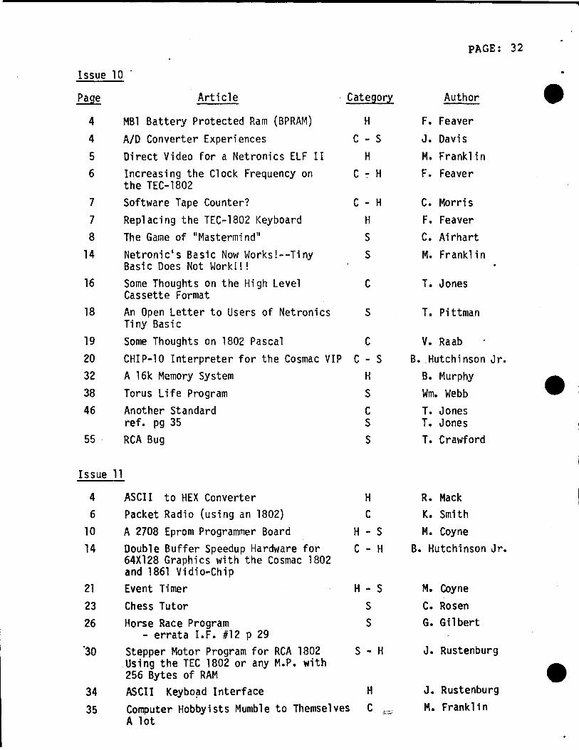
PAGE: 32
Issue 10
Page Arti cle . Category Author •4 MBl Battery Protected Ram (BPRAM) H F. Feaver4 AID Converter Experiences C - S J. Davis5 Direct Video for a Netronics ELF II H M. Franklin6 Increasing the Clock Frequency on C ':" H F. Feaver
the TEC-18027 Software Tape Counter? C - H C. Morris7 Replacing the TEC-1802 Keyboard H F. Feaver8 The Game of "Mastermind" S C. Airhart
14 Netronic's Basic Now Works!--Tiny S M. FranklinBasic Does Not Work!!!
16 Some Thoughts on the High Level C T. JonesCassette Format
18 An Open Letter to Users of Netronics S T. PittmanTi ny Basi c
19 Some Thoughts on 1802 Pascal C V. Raab20 CHIP-10 Interpreter for the Cosmac VIP C - S B•. Hutchi nson Jr.32 A 16k Memory System H B. Murphy •38 Torus Life Program S Wm. Webb46 Another Standard C T. Jones
ref. pg 35 S T. Jones55 RCA Bug S T. Crawford
Issue 11
4 ASCII to HEX Converter H R. Mack6 Packet Radio (using an 1802) C K. Smith
10 A 2708 Eprom Programmer Board H - S M. Coyne14 Double Buffer Speedup Hardware for C - H B. Hutchi nson Jr.
64X128 Graphics with the Cosmac 1802and 1861 Vidio-Chip
21 Event Timer H - S M. COyne23 Chess Tutor S C. Rosen26 Horse Race Program S G. Gilbert
- errata I.F. #12 p 29'30 Stepper Motor Program for RCA 1802 S - H J. Rustenburg
Using the TEC 1802 or any M.P. with •256 Bytes of RAM34 ASCII Keybo~d Interface H J. Rustenburg
35 Computer Hobbyists Mumble to Themselves C M. Franklini\.•• " ..,.,
A lot

PAGE: 33Issue 11 (Cont'd)
• Page Article Category Author
35 To VIP an ELF, Games and Video C - S L. ClockManipulation from RCA
- errata I.F. #12 p 29 M. Franklin39 Kilobaud 1802 Articles C M. Skodny39 Tiny Basic Notes C - S J. Smith40 Tec-1802 Editor Corrections and C - S F. Feaver
Enhancements42 More About Hardware Basics C F. Feaver42 Adding a Math Function to Your 1802 C F. Feaver43 Make Your Own Power Transformers C - H K. Bevis47 Annotated Bibliography of Articles C E. Fleming
Pertaining to 1802 Uses
Issue 12
4 Data Acquisition/Controller Subsystem C - H W. Greason.14 Video Voice S D. Roberts
• 15 ELF Writer S R• Moffie19 Simon ELF S R. ~10ffi e22 More on Subroutine Calling Conventions C w. Bowdish24 2708 Eprom Programmer S - H B. Erick28 On Standards C D. Jaeger30 Some Thoughts on Device Independent I/O C w. Bowdish49 1001 Options for the 1802 C - H M. Franklin55 To VIP an ELF, Part II S M. Frankln60 1802 Editor/Assembler C - S G• Miller
•

MEMBERSHIP RENEWAL/CHANGE Of ADDRESS PAGE: 34
The dues for the new club year, September 1979 to August 1980are as follows:
Canada ••••••••••••••••• $15.00Elsewhere ••••••••••••••• $18.00
These new rates include provision for FIRST CLASS POSTAGE whichshould ensure that your copy of IPSO FACTO arrives as quickly aspossible.
•Please make cheque payable to "THE ASSOCIATION OF
EXPERIMENTERS" and mail to c/o M.E. Franklin, Treasurer,24 Duby Road, Acton, Ontario, CANADA L7J 2Pl.
COMPUTERA.C.E. ,
~ '... -..'.' .
Do you have any friends? If so, they might well appreciate agift sUbscription to IPSO FACTO.
New members are required to pay the full dues for the ~current
year and will receive all the IPSO FACTO issues for the current year(Se~tember1979 to August 1980). Back issues may be purchased for$30.00 (Issues 1-12, May 1977 - May 1979).
CHANGE OF ADDRESS
~~tIIIIOTIIIrlhffrriIiJIIITIIj
_BL=E
•
NEW SUBSCRIPTION
ATTACH MAILING LABEL HERE
FOR CHANGE OF ADDRESS--------_.- .-_._-- -...- .....-
•