Ionizer Motion Sensor Installation, Operation and ...
3
TB-3059 Page 1 of 3 © 2014 DESCO INDUSTRIES, INC. Employee Owned Ionizer Motion Sensor Installation, Operation and Maintenance Description The Desco Ionizer Motion Sensor is designed to automatically activate an ionizer when an operator is present at a workstation and turn off when the workstation is vacant. This product ensures that the ionizer is activated when required. It also conserves energy and increases maintenance intervals of the ionizer by deactivating it when the workstation is vacant. The Control Unit is capable of switching up to 5 amps at 120VAC and is fuse protected. The Ionizer Motion Sensor consists of two components: the Sensor Unit and Control Unit. The control unit connects between the AC power cord and the ionizer power input using standard IEC type (C13/C14) connectors. The sensor unit is placed in a position to “detect” an operator up to three feet away. The sensitivity levels can be adjusted to: low (12 inches), medium (24 inches) or high (36 inches). The Sensor Unit should be mounted flush with the front edge of the mounting surface whenever possible. This is done to prevent reflected light from the mounting surface. The two components communicate using a standard 6-pin modular cable. The Ionizer Motion Sensor utilizes a unique infrared light and band pass filter to prevent interference from other light sources. The band pass filter uses a reflected infrared light with the specific frequency to sense the presence of the operator. It does not require continuous motion to remain activated. The deactivation delay time can be set to 1 minute, 10 minutes or 1 hour periods. This delay prevents the ionizer from turning on and off frequently if an operator is only away from the workstation momentarily. January 2014 Figure 1. Desco 60509 Ionizer Motion Sensor The Ionizer Motion Sensor is compatible with the following 120VAC Desco ionizers: TECHNICAL BULLETIN TB-3059 A. Power LED: This LED will illuminate blue when an operator or object has activated the device. B. Infrared Emitter and Receiver: Detects when an operator or object is present. Movement by the operator is not necessary. C. Communication Jacks: Use the included modular cables to connect the Sensor Unit to the Control Unit. D. DIP Switch: Use to adjust the sensor’s sensitivity and deactivation delay time. See the installation instructions on page 2 for more information. Figure 3. Control Unit features and components E G F C Figure 2. Sensor Unit features and components B A C D Item Description 60500 Chargebuster ® Jr. Bench Top Ionizer 60505 High Output Bench Top Ionizer 60640 Chargebuster ® 2-Fan Overhead Ionizer 60473 Chargebuster ® 3-Fan Overhead Ionizer Packaging 1 Sensor Unit 1 Control Unit, 120VAC 1 Modular Cable, 2' 1 Modular Cable, 7' 2 Hook and Loop Fastener Strips 2 Screws Features and Components Made in the United States of America 99 Washington Street Melrose, MA 02176 Phone 781-665-1400 Toll Free 1-800-517-8431 Visit us at www.TestEquipmentDepot.com
Transcript of Ionizer Motion Sensor Installation, Operation and ...

TB-3059 Page 1 of 3 © 2014 DESCO INDUSTRIES, INC.Employee Owned
Ionizer Motion SensorInstallation, Operation and Maintenance
DescriptionThe Desco Ionizer Motion Sensor is designed to automatically activate an ionizer when an operator is present at a workstation and turn off when the workstation is vacant. This product ensures that the ionizer is activated when required. It also conserves energy and increases maintenance intervals of the ionizer by deactivating it when the workstation is vacant. The Control Unit is capable of switching up to 5 amps at 120VAC and is fuse protected.
The Ionizer Motion Sensor consists of two components: the Sensor Unit and Control Unit. The control unit connects between the AC power cord and the ionizer power input using standard IEC type (C13/C14) connectors. The sensor unit is placed in a position to “detect” an operator up to three feet away. The sensitivity levels can be adjusted to: low (12 inches), medium (24 inches) or high (36 inches). The Sensor Unit should be mounted flush with the front edge of the mounting surface whenever possible. This is done to prevent reflected light from the mounting surface. The two components communicate using a standard 6-pin modular cable.
The Ionizer Motion Sensor utilizes a unique infrared light and band pass filter to prevent interference from other light sources. The band pass filter uses a reflected infrared light with the specific frequency to sense the presence of the operator. It does not require continuous motion to remain activated. The deactivation delay time can be set to 1 minute, 10 minutes or 1 hour periods. This delay prevents the ionizer from turning on and off frequently if an operator is only away from the workstation momentarily.
January 2014
Figure 1. Desco 60509 Ionizer Motion Sensor
The Ionizer Motion Sensor is compatible with the following 120VAC Desco ionizers:
TECHNICAL BULLETIN TB-3059
A. Power LED: This LED will illuminate blue when an operator or object has activated the device.
B. Infrared Emitter and Receiver: Detects when an operator or object is present. Movement by the operator is not necessary.
C. Communication Jacks: Use the included modular cables to connect the Sensor Unit to the Control Unit.
D. DIP Switch: Use to adjust the sensor’s sensitivity and deactivation delay time. See the installation instructions on page 2 for more information.
Figure 3. Control Unit features and components
E G
F C
Figure 2. Sensor Unit features and components
B
A C D
Item Description60500 Chargebuster® Jr. Bench Top Ionizer60505 High Output Bench Top Ionizer60640 Chargebuster® 2-Fan Overhead Ionizer60473 Chargebuster® 3-Fan Overhead Ionizer
Packaging1 Sensor Unit1 Control Unit, 120VAC1 Modular Cable, 2'1 Modular Cable, 7'2 Hook and Loop Fastener Strips2 Screws
Features and Components
Made in theUnited States of America
99 Washington Street Melrose, MA 02176 Phone 781-665-1400 Toll Free 1-800-517-8431
Visit us at www.TestEquipmentDepot.com

TB-3059 Page 2 of 3 © 2014 DESCO INDUSTRIES, INC.Employee Owned
E. IEC C14 Style Inlet: Connect the ionizer’s power cord here.
F. Fuse Drawer: Accepts 5A, 250V slow blow fuses.
G. IEC C13 Style Outlet: Connect into the ionizer’s power inlet.
Sensor ConfigurationThe Sensor’s sensitivity and deactivation delay time are controlled by the DIP switches located on the back of the Sensor Unit. Use the following tables for the DIP switch settings and their corresponding values.
NOTE: Be sure to disconnect the power from the Sensor Unit before making any changes to the DIP switch. Failure to do so may result in damage to the Sensor Unit.
SENSITIVITYDIP switches 1-3 control the sensitivity of Sensor.
Switch 1 Switch 2 Switch 3 Approximate Sensitivity
ON OFF OFF Low (0-12")OFF ON OFF Medium (12-24")OFF OFF ON High (24-36")
DEACTIVATION DELAY TIMEDIP switches 4-6 control the deactivation delay time.
Switch 4 Switch 5 Switch 6 Approximate Delay Time
ON OFF OFF 1 minuteOFF ON OFF 10 minuteOFF OFF ON 1 hour
default setting
Installation1. Ensure that the ionizer does not exceed the maximum
power rating of 120VAC, 5A. Insert the Control Unit into the ionizer’s IEC power inlet.
NOTE: If using the Desco 60505 High Output Bench Top Ionizer, set its power switch to ON before connecting the Control Unit. The Control Unit covers its power switch.
2. Determine the mounting location of the Sensor Unit.Place it where only the operator can come into its fieldof view. Do not place it where a fixture or item canobstruct its line of sight. Use either the included hookand loop fastener strips or screws to secure the sensorto a surface. The Sensor Unit should be mounted flushwith the front edge of the mounting surface wheneverpossible.
3. Use either the 2 foot or 7 foot modular cable to connectthe Control Unit to the Sensor Unit.
4. Connect the ionizer’s power cord to the Control Unit andthe opposite end into an appropriate power outlet.
5. Turn on / power the ionizer.
OperationEnter the sensor’s field of view. The blue LED will illuminate upon activation. The ionizer will remain powered as long as something is in the sensor’s view. Movement is not necessary.
Leave the sensor’s field of view to activate the shutoff delay timer. The Ionizer Motion Sensor’s LED will turn off and unpower the ionizer once the preset deactivation delay time is reached.
Figure 4. Using the Ionizer Motion Sensor with the 60505 High Output Bench Top Ionizer
Figure 5. Using the Ionizer Motion Sensor with the 60473 Chargebuster® 3-Fan Overhead Ionizer
TB-3059 Page 3 of 3 © 2014 DESCO INDUSTRIES, INC.Employee Owned
Limited WarrantyDesco expressly warrants that for a period of one (1) year from the date of purchase Desco Ionizer Motion Sensor will be free of defects in material (parts) and workmanship (labor). Within the warranty period, a credit for purchase of replacement Desco Ionizer Motion Sensor, or, at Desco’s option, the Ionizer Motion Sensor will be repaired or replaced free of charge. If product credit is issued, the amount will be calculated by multiplying the unused portion of the expected one year life times the original unit purchase price. Call our Customer Service Department at 909-627-8178 (Chino, CA) or 781-821-8370 (Canton, MA) for a Return Material Authorization (RMA) and proper shipping instructions and address. Please include a copy of your original packing slip, invoice, or other proof of date of purchase. Any unit under warranty should be shipped prepaid to the Desco factory. Warranty replacements will take approximately two weeks.If your unit is out of warranty, call our Customer Service Department at 909-627-8178 (Chino, CA) or 781-821-8370 (Canton, MA) for a Return Material Authorization (RMA) and proper shipping instructions and address. Desco will quote repair charges necessary to bring your unit up to factory standards.
Warranty ExclusionsTHE FOREGOING EXPRESS WARRANTY IS MADE IN LIEU OF ALL OTHER PRODUCT WARRANTIES, EXPRESSED AND IMPLIED, INCLUDING MERCHANTABILITY AND FITNESS FOR A PARTICULAR PURPOSE WHICH ARE SPECIFICALLY DISCLAIMED. The express warranty will not apply to defects or damage due to accidents, neglect, misuse, alterations, operator error, or failure to properly maintain, clean or repair products.
Limit of LiabilityIn no event will Desco or any seller be responsible or liable for any injury, loss or damage, direct or consequential, arising out of the use of or the inability to use the product. Before using, users shall determine the suitability of the product for their intended use, and users assume all risk and liability whatsoever in connection therewith.
SpecificationsMaximum Input 5A @ 120VAC
Fuse 5A, 250V, Slow Blow
Operating Temperature 32°F - 104°F (0 - 40°C)
Sensor Unit Dimensions 3.0" x 2.0" x 0.9"(7.6cm x 5.1cm x 2.3cm)
Control Unit Dimensions 2.7" x 2.0" x 1.8"(6.9cm x 5.1cm x 4.6cm)
Sensor Unit Weight 0.1 lbs (0.05 kg)
Control Unit Weight 0.3 lbs (0.1 kg)
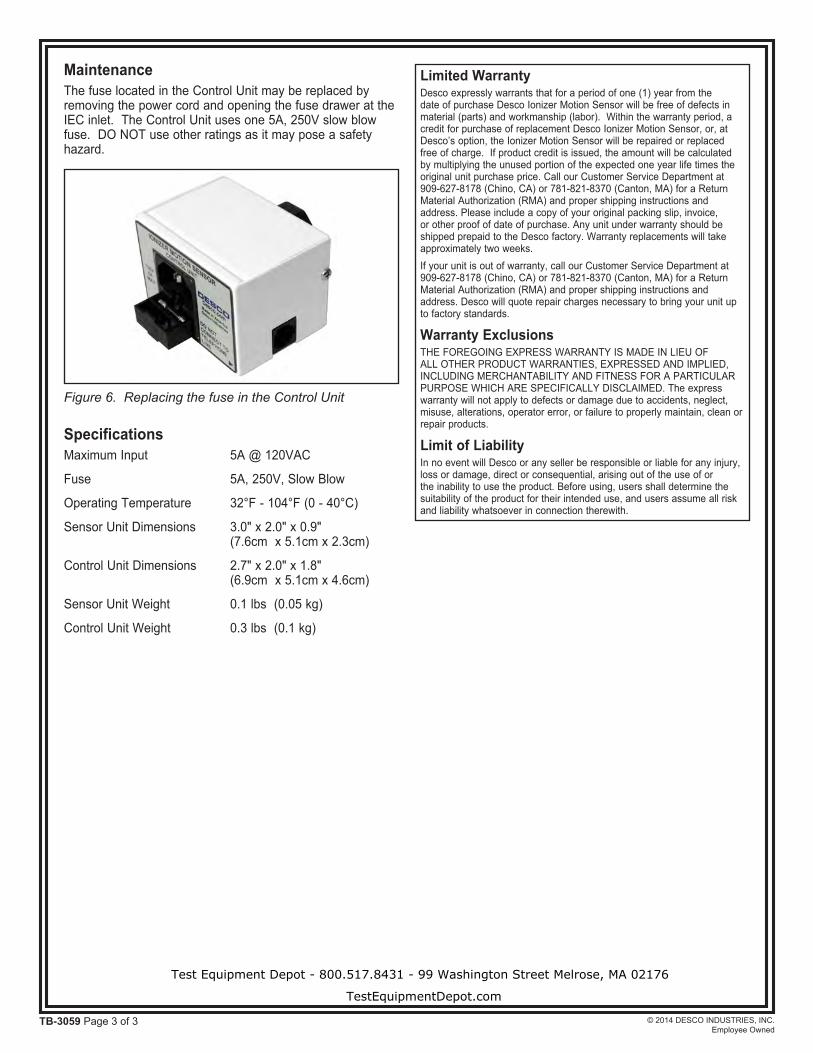
MaintenanceThe fuse located in the Control Unit may be replaced by removing the power cord and opening the fuse drawer at the IEC inlet. The Control Unit uses one 5A, 250V slow blow fuse. DO NOT use other ratings as it may pose a safety hazard.
Figure 6. Replacing the fuse in the Control Unit
Test Equipment Depot - 800.517.8431 - 99 Washington Street Melrose, MA 02176
TestEquipmentDepot.com