Inverter Structure - Solar Power | Off Grid and Grid …€œAero‐Sharp confidential. Do not...
21
“Aero‐Sharp confidential. Do not distribute without permission from Aero‐Sharp” Inverter Structure 1 Display Board Cover Grounding Display Ribbon Cable Driver Ribbon Cable “Aero‐Sharp confidential. Do not distribute without permission from Aero‐Sharp ” Control Board Driver Board
Transcript of Inverter Structure - Solar Power | Off Grid and Grid …€œAero‐Sharp confidential. Do not...

“Aero‐Sharp confidential. Do not distribute without permission from Aero‐Sharp”
Inverter Structure
1
Display Board
Cover Grounding
Display Ribbon Cable
Driver Ribbon Cable
“Aero‐Sharp confidential. Do not distribute without permission from Aero‐Sharp ”
Control Board
Driver Board

“Aero‐Sharp confidential. Do not distribute without permission from Aero‐Sharp”
Inverter Structure
Main-board
375V Bus connection
DC TVS component
AC TVS component
Fuse holder (fuse not inserted in this picture)
2“Aero‐Sharp confidential. Do not distribute without permission from Aero‐Sharp ”
“Aero‐Sharp confidential. Do not distribute without permission from Aero‐Sharp”
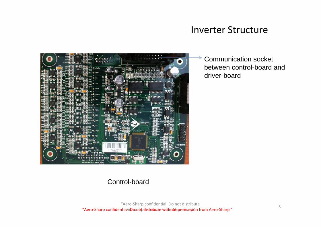
Inverter Structure
Control-board
Communication socket between control-board and driver-board
3“Aero‐Sharp confidential. Do not distribute without permission from Aero‐Sharp ”

“Aero‐Sharp confidential. Do not distribute without permission from Aero‐Sharp”
Inverter Structure
Display-board
4“Aero‐Sharp confidential. Do not distribute without permission from Aero‐Sharp ”

“Aero‐Sharp confidential. Do not distribute without permission from Aero‐Sharp”
Inverter Structure
“Aero‐Sharp confidential. Do not distribute without permission from Aero‐Sharp ”
Driver Board in Blue Color

“Aero‐Sharp confidential. Do not distribute without permission from Aero‐Sharp”
Field Service GuideHow to read the Inverter serial number:
X01 015 11 08 02 0238
Product Series Number
Power Product Year
Product Month
Production Batch of the
Month
Unit Number in this Production
batch
6“Aero‐Sharp confidential. Do not distribute without permission from Aero‐Sharp ”

“Aero‐Sharp confidential. Do not distribute without permission from Aero‐Sharp”
Field Service GuideCommon field service procedure: (Fill in the Field Service Form) (Create a
field service form)1. Record the user’s information: Owner's name, Address, phone, email2. Service technician name, company, service date3. Record the inverter’s serial number.4. Number of panels in string A, number of panels in string B5. Record the panel’s information (Voc, Isc, Vmp, Imp, Power, Temp. Coeff.
Manufacturer, model number). Check the system configuration.6. Check the correctness of the system configuration (use the quick assessment
way)7. Check the DC isolator, AC isolator and wire connection.8. Check the grid voltage against the specification on the inverter label. Contact
the utility company if the voltage is beyond the specification. 9. Check the DC voltage range. It should between 150 to 400V.10. Restart the system: First switch off the AC, then switch off DC. Wait for at
least 10 min. before you open the inverter’s cover. This allows the internal capacitors to discharge.
11. Open the Cover. (Follow the Inverter Open Procedure.)12.Do service work.13.Upgrading procedures (example: replace fuse)• Replace the water sealing gasket• Reinstall the cover after service . (Follow the Inverter Cover Installation
Procedure.) 7“Aero‐Sharp confidential. Do not distribute without permission from Aero‐Sharp ”

“Aero‐Sharp confidential. Do not distribute without permission from Aero‐Sharp”
Open the inverter
1. Unplug the DC and AC cables from the inverter2. Unscrew the four screws using an allen driver.3. Open the cover carefully and unplug the display
ribbon cable and the cover grounding wire.
8
Cover Grounding
Display Ribbon Cable
Field Service Guide
Driver Ribbon Cable
“Aero‐Sharp confidential. Do not distribute without permission from Aero‐Sharp ”
“Aero‐Sharp confidential. Do not distribute without permission from Aero‐Sharp”
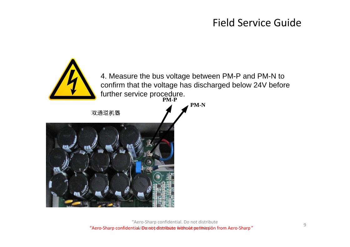
PM-PPM-N
9
4. Measure the bus voltage between PM-P and PM-N to confirm that the voltage has discharged below 24V before further service procedure.
Field Service Guide
“Aero‐Sharp confidential. Do not distribute without permission from Aero‐Sharp ”

“Aero‐Sharp confidential. Do not distribute without permission from Aero‐Sharp”
Field Service Guide
Cover Installation Procedure
1. Plug in and fully lock the display ribbon cable, then connect the cover grounding wire.
2. Make sure the water-sealing gasket sits properly along the edge of the inverter box when install the cover. This is important for avoiding water-leakage.
3. Slightly tighten the four screws following diagonal order, then make the last few turns one by one.
4. You should be able to touch the tip of the screw from bottom but not allowing the screw tip protrude the screw hole.
10
gasket
Pay attention on installing the cover, avoid touching the display board
Ground Sheet
Display Ribbon Cable
“Aero‐Sharp confidential. Do not distribute without permission from Aero‐Sharp ”

“Aero‐Sharp confidential. Do not distribute without permission from Aero‐Sharp”
Field Service GuideReplace the Control Board
Make sure the ribbon cable connector is fully locked
11
Pay attention to the delicate pins underneath the control board
M3*8 Screw(4 corners)
Backside of the control board, all the pins need be fit well
“Aero‐Sharp confidential. Do not distribute without permission from Aero‐Sharp ”

“Aero‐Sharp confidential. Do not distribute without permission from Aero‐Sharp”
Select Control board Software Version
Inverter Power Inverter Identity Software version
1.5kW has fuse X01015‐CA‐3.08
1.5kW No fuse X01015‐CA‐3.11
2.0kW has fuse X01020‐CA‐3.08
2.0kW No fuse X01020‐CA‐3.11
3.0kW Has fuseDriver board is green
X01030‐CA‐3.06
3.0kW Has fuseDriver board is blue
X01030‐CA‐3.09
3.0kW No fuse X01030‐CA‐3.11
The software on the control board has several versions. Refer to the table for the version selection.
12
Field Service Guide
“Aero‐Sharp confidential. Do not distribute without permission from Aero‐Sharp ”

“Aero‐Sharp confidential. Do not distribute without permission from Aero‐Sharp”
Replace Display board
Remove the protection film on the LED screen.
13
Make sure the ribbon cable connector is fully locked
Field Service Guide
“Aero‐Sharp confidential. Do not distribute without permission from Aero‐Sharp ”

“Aero‐Sharp confidential. Do not distribute without permission from Aero‐Sharp”
Gird Volt Error1. Check the grid voltage against the specification
on the inverter label.
2. If the voltage is within the specification range, open the inverter cover.
3. Measure the white resistor (see right picture). If the resistance is beyond 32-34Ω,replace the inverter.
4. Otherwise, measure the fuse. If it is broken, replace it. Select the proper fuse from the chart.
5. If the fuse is good but the problem stays, replace the inverter.
14
X01-010 16A Fuse
X01-015 20A Fuse
X01-020 25A Fuse
X01-028/030 32A Fuse
Field Service Guide
“Aero‐Sharp confidential. Do not distribute without permission from Aero‐Sharp ”

“Aero‐Sharp confidential. Do not distribute without permission from Aero‐Sharp”
“System Error” (may have other errors together) or “Grid Freq Err” or “Please Wait”
1. Check the system configuration.
2. Turn off and turn on the inverter. If the problem stays, open the inverter cover.
3. Replace the control board with the suitable software version. Pay attention to the pins underneath.
4. Replace the driver ribbon cable and the display ribbon cable. Make sure the connectors are fully locked.
3. Reinstall the inverter. If the problem stays, replace the inverter.
15
Field Service Guide
“Aero‐Sharp confidential. Do not distribute without permission from Aero‐Sharp ”

“Aero‐Sharp confidential. Do not distribute without permission from Aero‐Sharp”
TVS Failure Dismantling of TVS: Press the buckles of the TVS with slotted
screwdriver and pull out the side pin simultaneously, following the same step to pull out the second and third pin to dismantle the failed TVS. The dismantling of TVS is indicated in the below picture.
2
16
Field Service Guide
TVS components need be replaced
“Aero‐Sharp confidential. Do not distribute without permission from Aero‐Sharp ”
“Aero‐Sharp confidential. Do not distribute without permission from Aero‐Sharp”
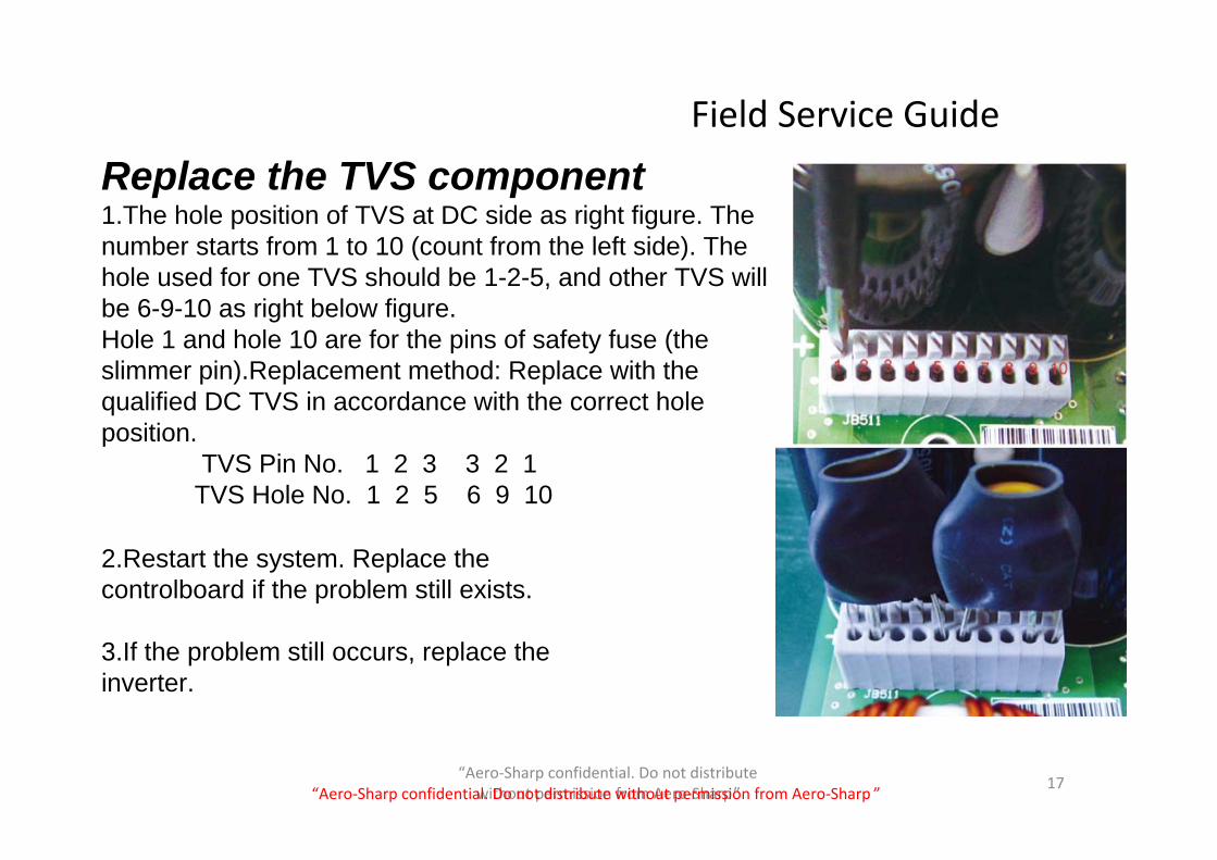
Replace the TVS component1.The hole position of TVS at DC side as right figure. The number starts from 1 to 10 (count from the left side). The hole used for one TVS should be 1-2-5, and other TVS will be 6-9-10 as right below figure.Hole 1 and hole 10 are for the pins of safety fuse (the slimmer pin).Replacement method: Replace with the qualified DC TVS in accordance with the correct hole position. TVS Pin No. 1 2 3 3 2 1 TVS Hole No. 1 2 5 6 9 10
2.Restart the system. Replace the controlboard if the problem still exists.
3.If the problem still occurs, replace the inverter.
17
Field Service Guide
“Aero‐Sharp confidential. Do not distribute without permission from Aero‐Sharp ”

“Aero‐Sharp confidential. Do not distribute without permission from Aero‐Sharp”
No Display or RXD Failure
1. Replace the control board2. Replace the display board 3. Replace the driver ribbon cable and the display ribbon cable 4. Reinstall the inverter and restart the system. 5. If the problem stays, replace the inverter.
18
Field Service Guide
“Aero‐Sharp confidential. Do not distribute without permission from Aero‐Sharp ”

“Aero‐Sharp confidential. Do not distribute without permission from Aero‐Sharp”
AC Breaker Triggers
Water-Leakage
Noisy
1. Turn off and turn on the system.2. If the problem stays, replace the inverter.
Replace the inverter.
1. Check the mounting wall. May cause by vibration. If the wall is not sturdy, find a different place to mount the inverter. Or take some measure.
2. Otherwise, replace the inverter.
19
Field Service Guide
“Aero‐Sharp confidential. Do not distribute without permission from Aero‐Sharp ”

“Aero‐Sharp confidential. Do not distribute without permission from Aero‐Sharp”
Battery Failure1. Replace the display board.2. Reinstall the inverter and restart the system. 3. If the problem stays, replace the inverter.
20
Foggy Display Window1.Dismount the Display board.2.Wipe the inside of the display window with alcohol.3.Reinstall the inverter.
Field Service Guide
“Aero‐Sharp confidential. Do not distribute without permission from Aero‐Sharp ”

“Aero‐Sharp confidential. Do not distribute without permission from Aero‐Sharp”
Tools and backup components Quantity
Service instruction sheet 1
Allen Driver(M4) 1
Cross screwdriver(M3) 1
Fuse 16A*2; 20A*2; 25A*3; 32A*4
Water‐sealing gasket 1(depends on inverter’s power)
Alcohol 1Cleaning cloth 1
Small flat screwdriver 1
TVS components 2 sets
One control boards of each software version
(depends on inverter’s power)
Driver ribbon cable (20 wires) 1
Display ribbon cable (14 wires) 1
Display board 2
New inverter of the same power level
1
Carry-on Tools and Components
21
Field Service Guide
“Aero‐Sharp confidential. Do not distribute without permission from Aero‐Sharp ”