
INVERTEC V205-T DC & V205-T AC/DC TIG - Lincoln Electric
35
Operator’s Manual INVERTEC ® V205-T DC & V205-T AC/DC Register your machine: www.lincolnelectric.com/register Authorized Service and Distributor Locator: www.lincolnelectric.com/locator IM937 | Issue Date Jan- 14 © Lincoln Global, Inc. All Rights Reserved. For use with machines having Code Numbers: 11426, 11430 INVER INVERTEC V205-T TEC V205-T AC/DC AC/DC Save for future reference Date Purchased Code: (ex: 10859) Serial: (ex: U1060512345)
Transcript of INVERTEC V205-T DC & V205-T AC/DC TIG - Lincoln Electric

Operator’s Manual
INVERTEC ® V205-T DC & V205-T AC/DC
Register your machine: www.lincolnelectric.com/register
Authorized Service and Distributor Locator: www.lincolnelectric.com/locator
IM937 | Issue D ate Jan- 14
© Lincoln Global, Inc. All Rights Reserved.
For use with machines having Code Numbers:
11426, 11430
INVERINVERTEC V205-T
TECV205-T AC/DC
AC/DC
Save for future reference
Date Purchased
Code: (ex: 10859)
Serial: (ex: U1060512345)

THANK YOU FOR SELECTING A QUALITY PRODUCT BY LINCOLN ELEC TRIC.
Please examine Carton and equiPment Fordamage immediately
When this equipment is shipped, title passes to the purchaser uponreceipt by the carrier. Consequently, Claims for material damaged inshipment must be made by the purchaser against the transportationcompany at the time the shipment is received.
saFety dePends on you
Lincoln arc welding and cutting equipment is designed and built withsafety in mind. However, your overall safety can be increased byproper installation ... and thoughtful operation on your part. DO NOT INSTALL, OPERATE OR REPAIR THIS EQUIPMENT WITHOUT READING THIS MANUAL AND THE SAFETY PRECAUTIONSCONTAINED THROUGHOUT. And, most importantly, think before youact and be careful.
This statement appears where the information must be followedexactly to avoid serious personal injury or loss of life.
This statement appears where the information must be followed toavoid minor personal injury or damage to this equipment.
KeeP your head out oF the Fumes.
DON’T get too close to the arc. Usecorrective lenses if necessary tostay a reasonable distance awayfrom the arc.
READ and obey the Material SafetyData Sheet (MSDS) and the warninglabel that appears on all containersof welding materials.
USE ENOUGH VENTILATION orexhaust at the arc, or both, to keepthe fumes and gases from your breathing zone and the general area.
IN A LARGE ROOM OR OUTDOORS, natural ventilation may beadequate if you keep your head out of the fumes (See below).
USE NATURAL DRAFTS or fans to keep the fumes away from yourface.
If you de velop unusual symptoms, see your supervisor. Perhaps thewelding atmosphere and ventilation system should be checked.
wear CorreCt eye, ear & body ProteCtion
PROTECT your eyes and face with welding helmetproperly fitted and with proper grade of filter plate(See ANSI Z49.1).
PROTECT your body from welding spatter and arcflash with protective clothing including woolenclothing, flame-proof apron and gloves, leatherleggings, and high boots.
PROTECT others from splatter, flash, and glare withprotective screens or barriers.
IN SOME AREAS, protection from noise may beappropriate.
BE SURE protective equipment is in good condition.
Also, wear safety glasses in work area AT ALLTIMES.
SPECIAL SITUATIONSDO NOT WELD OR CUT containers or materials which previously hadbeen in contact with hazardous substances unless they are properlycleaned. This is extremely dangerous.
DO NOT WELD OR CUT painted or plated parts unless specialprecautions with ventilation have been taken. They can release highlytoxic fumes or gases.
Additional precautionary measuresPROTECT compressed gas cylinders from excessive heat, mechanicalshocks, and arcs; fasten cylinders so they cannot fall.
BE SURE cylinders are never grounded or part of an electrical circuit.
REMOVE all potential fire hazards from welding area.
ALWAYS HAVE FIRE FIGHTING EQUIPMENT READY FORIMMEDIATE USE AND KNOW HOW TO USE IT.
WARNING
CAUTION

SECTION A:WARNINGS
CALIFORNIA PROPOSITION 65 WARNINGS
Diesel EnginesDiesel engine exhaust and some of its constituents are known to the State of California to cause cancer, birth defects, and otherreproductive harm.
Gasoline EnginesThe engine exhaust from this product contains chemicals known to the State of California to cause cancer, birth defects, or otherreproductive harm.
arC welding Can be hazardous. ProteCtyourselF and others From Possible seriousinJury or death. KeeP Children away. PaCe-maKer wearers should Consult with theirdoCtor beFore oPerating.
Read and understand the following safety highlights. For additionalsafety information, it is strongly recommended that you purchase acopy of “Safety in Welding & Cutting - ANSI Standard Z49.1” from theAmerican Welding Society, P.O. Box 351040, Miami, Florida 33135 orCSA Standard W117.2-1974. A Free copy of “Arc Welding Safety”booklet E205 is available from the Lincoln Electric Company, 22801St. Clair Avenue, Cleveland, Ohio 44117-1199.
BE SURE THAT ALL INSTALLATION, OPERATION,MAINTENANCE AND REPAIR PROCEDURES AREPERFORMED ONLY BY QUALIFIED INDIVIDUALS.
FOR ENGINE POWEREDEQUIPMENT.
1.a. Turn the engine off before troubleshootingand maintenance work unless themaintenance work requires it to be running.
1.b. Operate engines in open, well-ventilatedareas or vent the engine exhaust fumes outdoors.
1.c. Do not add the fuel near an open flamewelding arc or when the engine is running.Stop the engine and allow it to cool beforerefueling to prevent spilled fuel fromvaporizing on contact with hot engine partsand igniting. Do not spill fuel when fillingtank. If fuel is spilled, wipe it up and do not start engine untilfumes have been eliminated.
1.d. Keep all equipment safety guards, covers anddevices in position and in good repair.Keephands, hair, clothing and tools away from V-belts, gears, fans and all other moving partswhen starting, operating or repairingequipment.
1.e. In some cases it may be necessary to remove safety guards toperform required maintenance. Remove guards only whennecessary and replace them when the maintenance requiringtheir removal is complete. Always use the greatest care whenworking near moving parts.
1.f. Do not put your hands near the engine fan. Do not attempt tooverride the governor or idler by pushing on the throttle controlrods while the engine is running.
1.g. To prevent accidentally starting gasoline engines while turningthe engine or welding generator during maintenance work,disconnect the spark plug wires, distributor cap or magneto wireas appropriate.
1.h. To avoid scalding, do not remove the radiatorpressure cap when the engine is hot.
ELECTRIC ANDMAGNETIC FIELDS MAYBE DANGEROUS
2.a. Electric current flowing through any conductorcauses localized Electric and Magnetic Fields (EMF). Weldingcurrent creates EMF fields around welding cables and weldingmachines
2.b. EMF fields may interfere with some pacemakers, and weldershaving a pacemaker should consult their physician beforewelding.
2.c. Exposure to EMF fields in welding may have other health effectswhich are now not known.
2.d. All welders should use the following procedures in order tominimize exposure to EMF fields from the welding circuit:
2.d.1. Route the electrode and work cables together - Securethem with tape when possible.
2.d.2. Never coil the electrode lead around your body.
2.d.3. Do not place your body between the electrode and workcables. If the electrode cable is on your right side, thework cable should also be on your right side.
2.d.4. Connect the work cable to the workpiece as close as pos-sible to the area being welded.
2.d.5. Do not work next to welding power source.
3
SAFETY

ELECTRIC SHOCK CAN KILL.
3.a. The electrode and work (or ground) circuits areelectrically “hot” when the welder is on. Donot touch these “hot” parts with your bare skinor wet clothing. Wear dry, hole-free gloves to insulate hands.
3.b. Insulate yourself from work and ground using dry insulation.Make certain the insulation is large enough to cover your full areaof physical contact with work and ground.
in addition to the normal safety precautions, if
welding must be performed under electrically
hazardous conditions (in damp locations or while
wearing wet clothing; on metal structures such as
floors, gratings or scaffolds; when in cramped
positions such as sitting, kneeling or lying, if there
is a high risk of unavoidable or accidental contact
with the workpiece or ground) use the following
equipment:
• Semiautomatic DC Constant Voltage (Wire) Welder.
• DC Manual (Stick) Welder.
• AC Welder with Reduced Voltage Control.
3.c. In semiautomatic or automatic wire welding, the electrode,electrode reel, welding head, nozzle or semiautomatic weldinggun are also electrically “hot”.
3.d. Always be sure the work cable makes a good electricalconnection with the metal being welded. The connection shouldbe as close as possible to the area being welded.
3.e. Ground the work or metal to be welded to a good electrical (earth)ground.
3.f. Maintain the electrode holder, work clamp, welding cable andwelding machine in good, safe operating condition. Replacedamaged insulation.
3.g. Never dip the electrode in water for cooling.
3.h. Never simultaneously touch electrically “hot” parts of electrodeholders connected to two welders because voltage between thetwo can be the total of the open circuit voltage of bothwelders.
3.i. When working above floor level, use a safety belt to protectyourself from a fall should you get a shock.
3.j. Also see It ems 6.c. and 8.
ARC RAYS CAN BURN.
4.a. Use a shield with the proper filter and cover plates to protect youreyes from sparks and the rays of the arc when welding orobserving open arc welding. Headshield and filter lens shouldconform to ANSI Z87. I standards.
4.b. Use suitable clothing made from durable flame-resistant materialto protect your skin and that of your helpers from the arc rays.
4.c. Protect other nearby personnel with suitable, non-flammablescreening and/or warn them not to watch the arc nor exposethemselves to the arc rays or to hot spatter or metal.
FUMES AND GASESCAN BE DANGEROUS.
5.a. Welding may produce fumes and gaseshazardous to health. Avoid breathing thesefumes and gases. When welding, keep your head out of the fume.Use enough ventilation and/or exhaust at the arc to keep fumes
and gases away from the breathing zone. when welding
with electrodes which require special ventilation
such as stainless or hard facing (see instructions
on container or msds) or on lead or cadmium
plated steel and other metals or coatings which
produce highly toxic fumes, keep exposure as low
as possible and within applicable osha Pel and
aCgih tlV limits using local exhaust or
mechanical ventilation. in confined spaces or in
some circumstances, outdoors, a respirator may
be required. additional precautions are also
required when welding on galvanized steel.
5. b. The operation of welding fume control equipment is affected byvarious factors including proper use and positioning of theequipment, maintenance of the equipment and the specificwelding procedure and application involved. Worker exposurelevel should be checked upon installation and periodicallythereafter to be certain it is within applicable OSHA PEL andACGIH TLV limits.
5.c. Do not weld in locations near chlorinated hydrocarbon vaporscoming from degreasing, cleaning or spraying operations. Theheat and rays of the arc can react with solvent vapors to formphosgene, a highly toxic gas, and other irritating products.
5.d. Shielding gases used for arc welding can displace air and causeinjury or death. Always use enough ventilation, especially inconfined areas, to insure breathing air is safe.
5.e. Read and understand the manufacturer’s instructions for thisequipment and the consumables to be used, including thematerial safety data sheet (MSDS) and follow your employer’ssafety practices. MSDS forms are available from your weldingdistributor or from the manufacturer.
5.f. Also see item 1.b.
4
SAFETY

WELDING AND CUTTINGSPARKS CAN CAUSEFIRE OR EXPLOSION.
6.a. Remove fire hazards from the welding area. Ifthis is not possible, cover them to prevent thewelding sparks from starting a fire. Remember that weldingsparks and hot materials from welding can easily go throughsmall cracks and openings to adjacent areas. Avoid welding nearhydraulic lines. Have a fire extinguisher readily available.
6.b. Where compressed gases are to be used at the job site, specialprecautions should be used to prevent hazardous situations.Refer to “Safety in Welding and Cutting” (ANSI Standard Z49.1)and the operating information for the equipment being used.
6.c. When not welding, make certain no part of the electrode circuit istouching the work or ground. Accidental contact can causeoverheating and create a fire hazard.
6.d. Do not heat, cut or weld tanks, drums or containers until theproper steps have been taken to insure that such procedures willnot cause flammable or toxic vapors from substances inside.They can cause an explosion even though they have been“cleaned”. For information, purchase “Recommended SafePractices for the Preparation for Welding and Cutting ofContainers and Piping That Have Held Hazardous Substances”,AWS F4.1 from the American Welding Society (see addressabove).
6.e. Vent hollow castings or containers before heating, cutting orwelding. They may explode.
6.f. Sparks and spatter are thrown from the welding arc. Wear oil freeprotective garments such as leather gloves, heavy shirt, cufflesstrousers, high shoes and a cap over your hair. Wear ear plugswhen welding out of position or in confined places. Always wearsafety glasses with side shields when in a welding area.
6.g. Connect the work cable to the work as close to the welding areaas practical. Work cables connected to the building framework orother locations away from the welding area increase thepossibility of the welding current passing through lifting chains,crane cables or other alternate circuits. This can create firehazards or overheat lifting chains or cables until they fail.
6.h. Also see item 1.c.
6.I. Read and follow NFPA 51B “ Standard for Fire Prevention DuringWelding, Cutting and Other Hot Work”, available from NFPA, 1Batterymarch Park, PO box 9101, Quincy, Ma 022690-9101.
6.j. Do not use a welding power source for pipe thawing.
CYLINDER MAY EXPLODE IFDAMAGED.
7.a. Use only compressed gas cylinders containingthe correct shielding gas for the process usedand properly operating regulators designed forthe gas and pressure used. All hoses, fittings,etc. should be suitable for the application andmaintained in good condition.
7.b. Always keep cylinders in an upright position securely chained toan undercarriage or fixed support.
7.c. Cylinders should be located:
• Away from areas where they may be struck or subjectedto physical damage.
• A safe distance from arc welding or cutting operationsand any other source of heat, sparks, or flame.
7.d. Never allow the electrode, electrode holder or any otherelectrically “hot” parts to touch a cylinder.
7.e. Keep your head and face away from the cylinder valve outletwhen opening the cylinder valve.
7.f. Valve protection caps should always be in place and hand tightexcept when the cylinder is in use or connected for use.
7.g. Read and follow the instructions on compressed gas cylinders,associated equipment, and CGA publication P-l, “Precautions forSafe Handling of Compressed Gases in Cylinders,” availablefrom the Compressed Gas Association 1235 Jefferson DavisHighway, Arlington, VA 22202.
FOR ELECTRICALLYPOWERED EQUIPMENT.
8.a. Turn off input power using the disconnectswitch at the fuse box before working on theequipment.
8.b. Install equipment in accordance with the U.S. National ElectricalCode, all local codes and the manufacturer’s recommendations.
8.c. Ground the equipment in accordance with the U.S. NationalElectrical Code and the manufacturer’s recommendations.
refer to
http://www.lincolnelectric.com/safety
for additional safety information.
5
SAFETY
Welding SafetyInteractive Web Guidefor mobile devices

6
SAFETY
ELECTROMAGNETICCOMPATIBILITY (EMC)
ConFormanCe
Products displaying the CE mark are in conformity with EuropeanCommunity Council Directive of 3 May 1989 on the approximation ofthe laws of the Member States relating to electromagnetic compat-ibility (89/336/EEC). It was manufactured in conformity with a nationalstandard that implements a harmonized standard: EN 60974-10Electromagnetic Compatibility (EMC) Product Standard for Arc WeldingEquipment. It is for use with other Lincoln Electric equipment. It isdesigned for industrial and professional use.
introduCtion
All electrical equipment generates small amounts of electromagneticemission. Electrical emission may be transmitted through power linesor radiated through space, similar to a radio transmitter. Whenemissions are received by other equipment, electrical interferencemay result. Electrical emissions may affect many kinds of electricalequipment; other nearby welding equipment, radio and TV reception,numerical controlled machines, telephone systems, computers, etc.Be aware that interference may result and extra precautions may berequired when a welding power source is used in a domestic estab-lishment.
installation and use
The user is responsible for installing and using the welding equipmentaccording to the manufacturer’s instructions. If electromagneticdisturbances are detected then it shall be the responsibility of theuser of the welding equipment to resolve the situation with thetechnical assistance of the manufacturer. In some cases this remedialaction may be as simple as earthing (grounding) the welding circuit,see Note. In other cases it could involve construction of an electro-magnetic screen enclosing the power source and the work completewith associated input filters. In all cases electromagnetic disturbancesmust be reduced to the point where they are no longer troublesome.Note: The welding circuit may or may not be earthed for safety reasons
according to national codes. Changing the earthing arrangements shouldonly be authorized by a person who is competent to access whether thechanges will increase the risk of injury, e.g., by allowing parallel weldingcurrent return paths which may damage the earth circuits of other equip-ment.
assessment oF area
Before installing welding equipment the user shall make anassessment of potential electromagnetic problems in the surroundingarea. The following shall be taken into account:a. other supply cables, control cables, signaling and telephone cables;above, below and adjacent to the welding equipment;
b. radio and television transmitters and receivers;
c. computer and other control equipment;
d. safety critical equipment, e.g., guarding of industrial equipment;
e. the health of the people around, e.g., the use of pacemakers andhearing aids;
f. equipment used for calibration or measurement
g. the immunity of other equipment in the environment. The user shallensure that other equipment being used in the environment iscompatible. This may require additional protection measures;
h. the time of day that welding or other activities are to be carried out.
The size of the surrounding area to be considered will depend on thestructure of the building and other activities that are taking place. Thesurrounding area may extend beyond the boundaries of the premises.
methods oF reduCing emissions
Mains Supply
Welding equipment should be connected to the mains supplyaccording to the manufacturer’s recommendations. If interferenceoccurs, it may be necessary to take additional precautions such asfiltering of the mains supply. Consideration should be given toshielding the supply cable of permanently installed weldingequipment, in metallic conduit or equivalent. Shielding should beelectrically continuous throughout its length. The shielding should beconnected to the welding power source so that good electrical contactis maintained between the conduit and the welding power sourceenclosure.
Maintenance of the Welding Equipment
The welding equipment should be routinely maintained according tothe manufacturer’s recommendations. All access and service doorsand covers should be closed and properly fastened when the weldingequipment is in operation. The welding equipment should not bemodified in any way except for those changes and adjustmentscovered in the manufacturers instructio ns. In particular, the sparkgaps of arc striking and stabilizing devices should be adjusted andmaintained according to the manufacturer’s recommendations.
Welding Cables
The welding cables should be kept as short as possible and should bepositioned close together, running at or close to floor level.
Equipotential Bonding
Bonding of all metallic components in the welding installation andadjacent to it should be considered. However, metallic componentsbonded to the work piece will increase the risk that the operator couldreceive a shock by touching these metallic components and theelectrode at the same time. The operator should be insulated from allsuch bonded metallic components.
Earthing of the Workpiece
Where the workpiece is not bonded to earth for electrical safety, notconnected to earth because of its size and position, e.g., ships hull orbuilding steelwork, a connection bonding the workpiece to earth mayreduce emissions in some, but not all instances. Care should be takento prevent the earthing of the work piece increasing the risk of injuryto users, or damage to other electrical equipment. Where necessary,the connection of the workpiece to earth should be made by a directconnection to the work piece, but in some countries where directconnection is not permitted, the bonding should be achieved bysuitable capacitance, selected according to national regulations.
Screening and Shielding
Selective screening and shielding of other cables and equipment inthe surrounding area may alleviate problems of interference.Screening of the entire welding installation may be considered forspecial applications. 1 Portions of the preceding text are contained in EN 60974-10: “ElectromagneticCompatibility (EMC) product standard for arc welding equipment.”

7
TABLE OF CONTENTSV205-T DC & V205-T AC/DC
PageGeneral Description ................................................................................................................................................8Installation ................................................................................................................................................Section A
Technical Specifications................................................................................................................................A-1Select Suitable Location................................................................................................................................A-2Stacking .......................................................................................................................................................A-2Tilting ...........................................................................................................................................................A-2Environmental Area.......................................................................................................................................A-2Machine Grounding and High Frequency Interference Protection ...................................................................A-2Input Connections .........................................................................................................................................A-3Reconnect Procedure ....................................................................................................................................A-3
230V Input............................................................................................................................................A-4115V Input............................................................................................................................................A-4Attachment Plug Installation, Engine Driven Generator ..........................................................................A-4
Output Connections.......................................................................................................................................A-5Output and Gas Connection for Tig Welding...................................................................................................A-5Work Cable Connection .................................................................................................................................A-5Output Connection for Stick Welding .............................................................................................................A-5
Quick Disconnect Plug ..........................................................................................................................A-6Shielding Gas Connection .....................................................................................................................A-6Remote Control Connection...................................................................................................................A-6
_________________________________________________________________________________________Operation Section B
Safety Instructions ........................................................................................................................................B-1Welding Capability ........................................................................................................................................B-1Limitations....................................................................................................................................................B-1Rear Control Panel ........................................................................................................................................B-1Controls and Settings, 2 Step and 4 Step Tig Sequence..........................................................................B-2,B-4Welding Parameter Defaults and Ranges.......................................................................................................B-4Set Up Menu .................................................................................................................................................B-5Output Limitations ........................................................................................................................................B-6DC Tig Welding ............................................................................................................................................B-6Welding Polarity ............................................................................................................................................B-6
DC Electrode Negative Polarity..............................................................................................................B-6DC Electrode Positive Polarity ...............................................................................................................B-7D.C.-Pulsed TIG ....................................................................................................................................B-7A.C. (Alternating Current) ......................................................................................................................B-7A.C.-Pulsed TIG (Alternating Current Pulsed) .........................................................................................B-7
Steel Tig Welding ..........................................................................................................................................B-8Copper Tig Welding.......................................................................................................................................B-8Tips For AC TIG Welding................................................................................................................................B-8GTAW Process ..............................................................................................................................................B-8Protective Gas, Tips For Improved TIG Starting ..............................................................................................B-9AC Tig Welding Quick Start Up ....................................................................................................................B-10DC Tig Welding Quick Start Up ....................................................................................................................B-11
_________________________________________________________________________________________Accessories .............................................................................................................................Section C
Optional Accessories and Compatible Equipment .........................................................................C-1Factory, Field Installed .................................................................................................................C-1
________________________________________________________________________________Maintenance............................................................................................................................Section D
Safety Precautions.......................................................................................................................D-1Input Filter Capacitor Discharge Procedure ..................................................................................D-1Routine Maintenance ...................................................................................................................D-1
________________________________________________________________________________Troubleshooting.......................................................................................................................Section E
How to Use Troubleshooting Guide ...............................................................................................E-1Troubleshooting Guide....................................................................................................E-2 thru E-4
________________________________________________________________________________Wiring Diagram........................................................................................................................Section F
________________________________________________________________________________Parts Lists......................................................................................................................................P-560

8
GENERAL DESCRIPTIONV205-T DC & V205-T AC/DC
GENERAL DESCRIPTIONGENERAL DESCRIPTIONThe Invertec V205-T DC & V205-T AC/DC are industrial 200 amparc welding power sources that utilize single phase input power,to produce constant current output. The welding response hasbeen optimized for stick (SMAW) and TIG (GTAW). The units areideal for industrial applications where portability is important.
The Invertec V205-T AC/DC is a power source that can performthe following types of welding with excellent results:
• TIG AC with square, sinusoidal and triangular waveforms. • TIG DC (with high frequency or Touch Start TIG Starting)• Stick DC
The Invertec V205-T DC is a power source that can perform thefollowing types of welding with excellent results:
• TIG DC (with high frequency or Touch Start TIG Starting)• Stick DC
The following items can be connected to the 6 pin socket on thefront panel: • Remote control potentiometer for Stick welding.• Remote Foot Amptrol or Hand Amptrol• Arc Start Switch
NOTE: See Accessories section of this manual for product num-bers and complete description.

Input Amps
34A28A20A
34A25A20A
30A23A19A
30A18A15A
Output Amps Volts at Rated Amperes
(Stick) 110 24.4V90 23.6V70 22.8V
(TIG) 150 16V120 14.8V100 14V
(Stick) 180 27.2V150 26V130 25.2V
(TIG) 200 18V170 16V140 15.6V
Duty Cycle
(115V) 35%60%100%
(115V) 40%60%100%
(230V) 35%60%100%
(230V) 40%60%100%
Output Current Range
6-200 Amps
Maximum Open Circuit Voltage
54 Volts Max.
Type of Output
DC (K2629-1)AC/DC (K1855-4)
A-1
INSTALLATIONV205-T DC & V205-T AC/DC
TECHNICAL SPECIFICATIONS
INPUT - SINGLE PHASE ONLY
RATED OUTPUT
OUTPUT
PHYSICAL DIMENSIONS
* Note: Refer to RECONNECT PROCEDURE (Table A.1) forInput Voltage Operating Range.
RECOMMENDED INPUT WIRE AND FUSE SIZES(1)
Input Voltages * /50 /60 Hz.115230
Max. Input Current 34A at Rated Output 30A at Rated Output
Height
Width
Depth
Weight
15 in. (381 mm)
8.5 in. (216mm)
19 in. (483mm)
38 lbs. (17kg)
INPUT VOLTAGE /FREQUENCY (HZ)
115/50/60230/50/60
TYPE S, SO ST, STO, OREXTRA HARD USAGEINPUT CORD AWG
#12
TIME-DELAY CIRCUITBREAKER OR FUSESIZE (AMPS)
30 A
(1) Maximum Rated Output
TEMPERATURE RANGES
OPERATING TEMPERATURE RANGE-20°C to +40°C
STORAGE TEMPERATURE RANGE-50°C to +85°C
V205-T DC K2629-1 (Code Number 11426)V205-T AC/DC K1855-4 (Code Number 11430)

A-2
INSTALLATIONV205-T DC & V205-T AC/DC
Read entire installation section before startinginstallation.
SAFETY PRECAUTIONS
ELECTRIC SHOCK can kill.• Only qualified personnel should performthis installation.• Turn the input power OFF and unplug themachine from the receptacle before work-ing on this equipment. Allow machine to sitfor 5 minutes minimum to allow the powercapacitors to discharge before workinginside this equipment.
• Insulate yourself from the work and ground.• Always wear dry insulating gloves. • Always connect the V205-T to a power supply groundedaccording to the National Electrical Code and local codes.-------------------------------------------------------SELECT SUITABLE LOCATION
The Invertec will operate in harsh environments. Even so, it isimportant that simple preventative measures are followed in orderto assure long life and reliable operation.
• The machine must be located where there is free circulation ofclean air such that air movement in the back and out the frontwill not be restricted.
• Dirt and dust that can be drawn into the machine should be keptto a minimum. Failure to observe these precautions can result inexcessive operating temperatures and nuisance shutdown.
STACKING
The Invertec V205-T DC & V205-T AC/DC can not be stacked.
TILTING
Place the machine directly on a secure, level surface. Themachine may topple over if this procedure is not followed.
ENVIRONMENTAL AREA
Keep the machine dry. Do not place it on wet ground or in pud-dles.
MACHINE GROUNDING AND HIGH FREQUENCYINTERFERENCE PROTECTION
The Capacitor Discharge Circuit used in the high frequency gener-ator, may cause many radio, TV and electronic equipment interfer-ence problems. These problems may be the result of radiatedinterference. Proper grounding methods can reduce or eliminateradiated interference.
The Invertec V205-T DC & V205-T AC/DC have been field testedunder recommended installation conditions. It complies with FCCallowable limits for radiation.
Radiated interference can develop in the following four ways:
1. Direct interference radiated from the welder.
2. Direct interference radiated from the welding leads.
3. Direct interference radiated from feedback into the powerlines.
4. Interference from re-radiation of “pickup” by ungrounded metallic objects.
Keeping these contributing factors in mind, installing equipmentper the following instructions should minimize problems.
1. Keep the welder power supply lines as short as possible andenclose as much of them as possible in rigid metallic conduitor equivalent shielding for a distance of 50 feet (15.2m). Thereshould be good electrical contact between this conduit and thewelder case ground. Both ends of the conduit should be con-nected to a driven ground and the entire length should be con-tinuous.
2. Keep the work and electrode leads as short as possible and asclose together as possible. Lengths should not exceed 25 ft(7.6m).
WARNING
A-3
INSTALLATIONV205-T DC & V205-T AC/DC
3. Be sure the torch and work cable rubber coverings are free ofcuts and cracks that allow high frequency leakage. Cableswith high natural rubber content, such as Lincoln Stable-Arc®
better resist high frequency leakage than neoprene and othersynthetic rubber insulated cables.
4. Keep the torch in good repair and all connections tight toreduce high frequency leakage.
5. The work terminal must be connected to a ground within tenfeet of the welder, using one of the following methods.
a) A metal underground water pipe in direct contact withthe earth for ten feet or more.
b) A 3/4” (19mm) galvanized pipe or a 5/8” (16mm) solidgalvanized iron, steel or copper rod driven at least eightfeet into the ground.
The ground should be securely made and the groundingcable should be as short as possible using cable of the samesize as the work cable, or larger. Grounding to the buildingframe electrical conduit or a long pipe system can result inre-radiation, effectively making these members radiatingantennas.
6. Keep all panels securely in place.
7. All electrical conductors within 50 ft (15.2m) of the weldershould be enclosed in grounded, rigid metallic conduit orequivalent shielding. Flexible metallic conduit is generally notsuitable.
8. When the welder is enclosed in a metal building, severalearth driven electrical grounds connected (as in 5b above)around the periphery of the building are recommended.
Failure to observe these recommended installation procedures cancause radio or TV interference problems.
INPUT CONNECTIONS
Be sure the voltage, phase, and frequency of the inputpower is as specified on the rating plate, located on the bottom ofthe machine.
ELECTRIC SHOCK can kill.
• Have a qualified electrician install andservice this equipment.
• Turn the input power OFF and unplug the machine from the receptaclebefore working on this equipment.
• Allow machine to sit for 5 minutes minimum to allow thepower capacitors to discharge before working inside thisequipment.
• Do not touch electrically hot parts.
• Machine must be plugged into a receptacle that is ground-ed according to the National Electrical Code and localcodes.
• Do not remove or defeat the purpose of the power cordground pin.
------------------------------------------------------------------
RECONNECT PROCEDURE
The Invertec V205-T DC & V205-T AC/DC auto reconnect to either115V or 230V supply.
This machine is capable of operating within the following inputvoltage ranges (Table A.1):
TABLE A.1
Fuse the input circuit with time delay fuses or delay type¹ circuitbreakers. Using fuses or circuit breakers smaller than recom-mended may result in “nuisance” shut-offs from welder inrushcurrents even if not welding at high currents.
The Invertec Power Source is recommended for use on an individ-ual branch circuit.
¹ Also called “inverse time” or “thermal/magnetic” circuit breakers. These circuitbreakers have a delay in tripping action that decreases as the magnitude of thecurrent increases.
WARNING
NOMINAL115V
208V / 230V
RANGE90-140V184-276V

A-4
INSTALLATIONV205-T DC & V205-T AC/DC
230V INPUT
The equipment is provided with a 230/115V cable, 6.6ft.(2m) inlength with a 230V 6-50P attachment plug.
The Invertec V205-T performs best when connected to 230VACinputs. This input allows full output of the machine (200 amps).
115V INPUT
A suitable 115V attachment plug must be installed on the power cordto use the V205-T with a 115V input supply. The rated output of theV205-T is available when connected to a 30A branch circuit. Whenconnected to a branch circuit with lower amp rating, lower weldingcurrent and duty cycle must be used. An output guide is providedbelow. The values are approximate and must be adjusted downwardif the fuse or circuit breaker trips off. Other loads on the circuit andfuse/circuit breaker characteristics will affect the available output. Donot exceed these welding conditions:
15A branch circuit10% duty cycleStick: 75A TIG: 105A
20A branch circuit10% duty cycleStick: 90A TIG: 130A
ATTACHMENT PLUG INSTALLATION
Connect the white (neutral) wire under terminal clamp with silverscrew, and black (hot) wire under terminal clamp with brassscrew. Connect green wire under terminal clamp with greenscrew.
• Failure to wire as instructed may cause personal injury ordamage to equipment. To be installed or checked by anelectrician or qualified person only.
------------------------------------------------------------------
In all cases, the green or green/yellow grounding wire must be con-nected to the grounding pin of the plug, usually identified by a greenscrew.
Attachment plugs must comply with the Standard for AttachmentPlugs and Receptacles, UL498.
The product is considered acceptable for use only when an attach-ment plug as specified is properly attached to the supply cord.
For use on engine drives, keep in mind the above input drawrestrictions and the following precaution.
ENGINE DRIVEN GENERATOR
The Invertec V205-T DC & V205-T AC/DC can be operated onengine driven generators as long as the 230 volt auxiliary meetsthe following conditions:• The AC waveform peak voltage is below 400 volts.• The AC waveform frequency is between 45 and 65Hz.
The following Lincoln engine drives meet these condi-tions whenrun in the high idle mode:• Ranger 250, 250 LPG, 305 G, 305 D*• Vantage 300, 400, 500 & Air Vantage 500*Some engine drives do not meet these conditions (e.g. MillerBobcats, etc). Operation of the Invertec V205-T AC/DC is not rec-ommended on engine drives not conforming to these conditions.Such drives may deliver unacceptably high voltage levels to theInvertec power source.
* Ranger and Vantage Engine Drives require the full KVA AdapterKit (K1816-1)
WARNING

A-5
INSTALLATIONV205-T DC & V205-T AC/DC
OUTPUT CONNECTIONSELECTRIC SHOCK can kill.• Keep the electrode holder, TIG torch andcable insulation in good condition and inplace.
• Do not touch electrically live parts or elec-trode with skin or wet clothing.
• Insulate yourself from work and ground.
• Turn the input line Switch on the Invertec V205-T DC & V205-T AC/DC “off” before connecting or disconnecting outputcables or other equipment.
-----------------------------------------------------------------
OUTPUT AND GAS CONNECTION FOR TIG WELDING(FIGURE A.1)
The TIG Torch Twist-Mate and work cable Twist-Mate Connectorsare supplied with thewelder. To connect the cables,turnthePowerSwitch“OFF”. Connect the torch cable Twist-Mate plug into the DC(-)Electrode/Gas Output Receptacle on the front of the welder andturn it clockwise until snug,(Do not Overtighten). This is a quickconnect terminal and also provides the gas connection for theshielding gas to the torch.
To avoid receiving a high frequency shock, keep the TIG torchand cable Insulation in good condition._________________________________________________
WORK CABLE CONNECTION
Next, connect the work cable to the “+” output terminal in thesame way.
To minimize high frequency interference, refer to MachineGrounding and High Frequency Interference Protection sectionof this manual for the proper procedure on grounding the workclamp and work piece.
This unit does not include a TIG torch, but one may be purchasedseparately. The accessories section of this manual lists a numberof Lincoln Electric TIG torches, and TIG Torch Starter Packs thatare recommended for use with this machine; however, any similarTIG torch can be used. To attach the Twist-Mate Plug to a LincolnTorch, slide the rubber boot onto the torch cable (enlarge the bootopening if necessary), screw the fitting on the torch cable into thebrass connector snugly and slide the boot back over the brass
connector.
OUTPUT CONNECTION FOR STICK WELDING (FIGUREA.2)
First determine the proper electrode polarity for the electrode tobe used. Consult the electrode data for this information. Thenconnect the output cables to the output terminals corresponding tothis polarity. For instance, for DC(+) welding, connect the elec-trode cable (which is connected to the electrode holder) to the “+”output terminal and the work cable (which is connected to thework clamp) to the “-” output terminal. Insert the connector withthe key lining up with the keyway, and rotate clockwise; until theconnection is snug. Do not over tighten.
WARNING
+
-
WORK CLAMPWORK CABLE
TIG TORCH
FIGURE A.1
TIG ADAPTER
RETAINING COMPOUND
STRAIN RELIEF BOOT
TIG TORCH POWER CABLE WITH GAS FITING
+
-
FIGURE A.2
WORK CABLE
WORK CABLE
STICK ELECTRODEHOLDER

A-6
INSTALLATIONV205-T DC & V205-T AC/DC
QUICK DISCONNECT PLUG (FOR STICK ELECTRODE CABLE andWORK CABLE)
A quick disconnect system is used for the welding cable connec-tions. The stick electrode cable will need to have a plug attached.
1. Cut off welding cable lug, if present.
2. Remove 1.00 in. (25mm) of welding cable insulation.
3. Slide rubber boot onto cable end. The boot end may betrimmed to match the cable diameter. Use soap or other non-petroleum-based lubricant to help slide the boot over thecable, if needed.
4. Insert copper strands into ferrule.
5. Slide the copper ferrule into the brass plug.
6. Tighten set screw to collapse copper tube. Screw must applypressure against welding cable. The top of the set screw willbe well below the surface of the brass plug after tightening.
7. Slide rubber boot over brass plug. The rubber boot must bepositioned to completely cover all electrical surfaces after theplug is locked into the receptacle.
SHIELDING GAS CONNECTION
Obtain the necessary inert shielding gas. Connect the cylinder ofgas with a pressure regulator and flow gage. Install a gas hosebetween the regulator and gas inlet (located on the rear of thewelder). The gas inlet has a 5/16-18 right hand female thread;CGA #032.
CYLINDER could explode if damaged.
• Keep cylinder upright and chained to asupport.
• Keep cylinder away from areas where it could bedamaged.
• Never allow the torch or welding electrode to touchthe cylinder.
• Keep cylinder away from live electrical circuits.------------------------------------------------------------------
REMOTE CONTROL CONNECTION
A remote control receptacle is provided on the lower center casefront of the welder for connecting a remote control to the machine.Refer to the Optional Accessories section of this manual for avail-able remote controls.
25 mm
1.00 in.
WELDING CABLE
BOOT
TRIM, IF REQ'D
TO FIT OVER CABLE
WELDING CABLE
COPPER FERRULE
SET SCREW
BRASS PLUGCOPPER TUBE
WARNING

B-1
OPERATIONV205-T DC & V205-T AC/DC
Read and understand this entire section before operatingyour machine.
SAFETY INSTRUCTIONS
ELECTRIC SHOCK can kill.
• Do not touch electrically live parts such asoutput terminals, electrode or internal wiring.• Insulate yourself from the work and ground.
• Always wear dry insulating gloves.------------------------------------------------------------------
FUMES AND GASEScan be dangerous.
• Keep your head out of fumes.
• Use ventilation or exhaust toremove fumes from breathingzone.
------------------------------------------------------------------
WELDING, CUTTING and GOUGING SPARKScan cause fire or explosion
•Keep flammable material away.
•Do not weld, cut or gouge oncontainers that have held combustibles.
------------------------------------------------------------------
ARC RAYScan burn.
• Wear eye, ear and bodyprotection.
------------------------------------------------------------------
Only qualified personnel should operate this equipment.Observe all safety information throughout this manual.
WELDING CAPABILITY
The Invertec V205-T DC & V205-T AC/DC is rated at 200 amps, 18volts, at 40% duty cycle on a ten minute basis. It is capable ofhigher duty cycles at lower output currents. It is capable of 140amps, 15.6 volts at at 100% duty cycle. If the duty cycle isexceeded, a thermal protector will shut off the output until themachine cools. See Technical Specifications in A-1 for other ratedoutputs.
The Invertec V205-T is recommended for stick welding with suchpopular electrodes as Fleetweld 5P and 5P+ (E6010), Fleetweld35 (E6011), Fleetweld 37 (E6013), Fleetweld 180 (E6011) andExcalibur 7018.
LIMITATIONS
The V205-T is not recommended for pipe thawing.
REAR CONTROL PANEL (FIGURE B.1)
• I1: Off/On switch turns on the electric power to the welder.It has two positions, "O" off, and "I" on.
------------------------------------------------------------------
* With "l1" in the "I" (ON) position, the welding machine is opera-tional and there is voltage between the positive (+) and negative(-) Terminals in stick welding. In TIG, the welding process needsa trigger closure command at the remote controlconnection.(Usually via an Arc Start Switch or Foot Amptrol)
* The welder is connected to the supply even if the “l1” (PowerSwitch) is in the "O" (Off) position, and therefore there are elec-trically live parts inside the power source. Carefully follow theinstructions given in this manual.
FIGURE B.1
* 1 : Supply cable* 2 : Gas attachmentl1 : Power Switch
WARNING
B-2
OPERATION
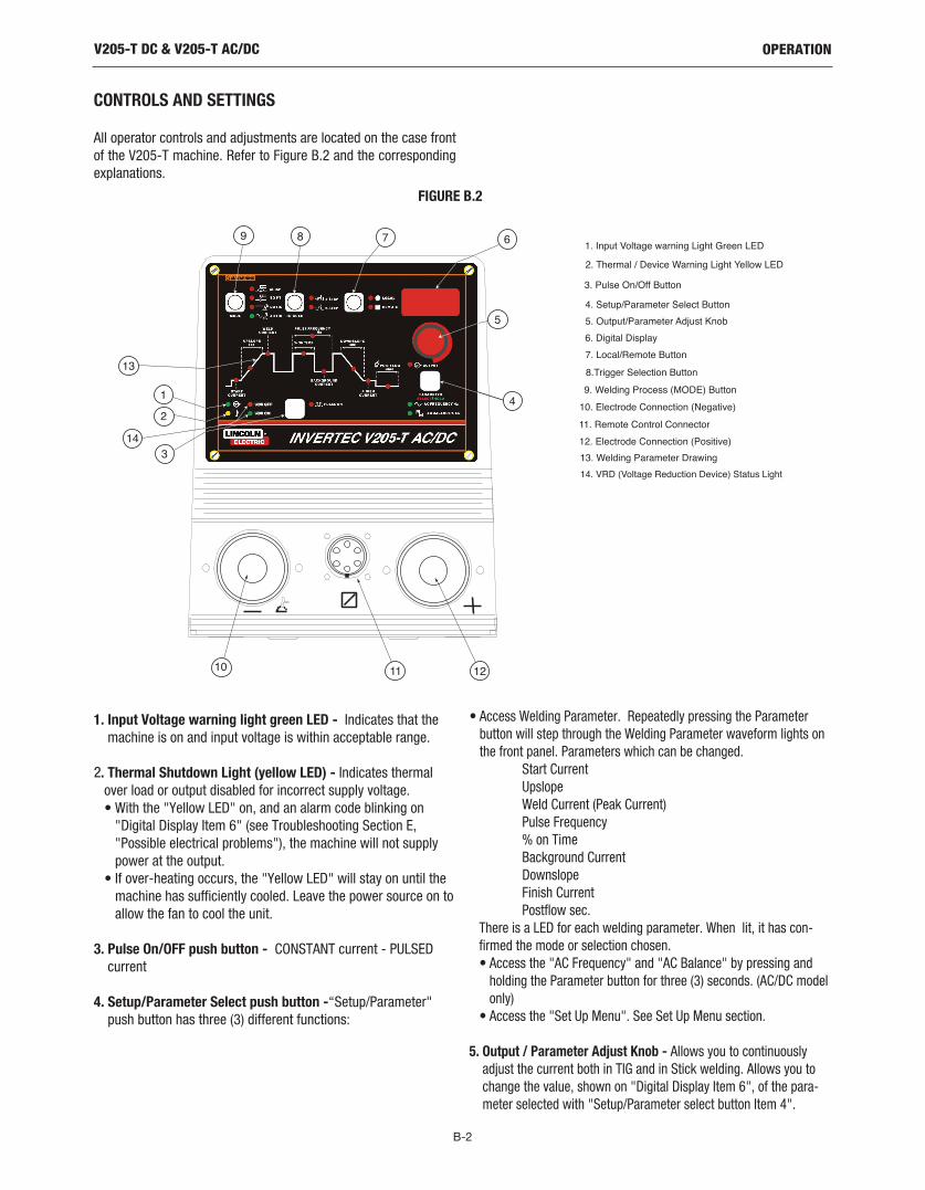
CONTROLS AND SETTINGS
All operator controls and adjustments are located on the case frontof the V205-T machine. Refer to Figure B.2 and the correspondingexplanations.
1. Input Voltage warning light green LED - Indicates that themachine is on and input voltage is within acceptable range.
2. Thermal Shutdown Light (yellow LED) - Indicates thermalover load or output disabled for incorrect supply voltage. • With the "Yellow LED" on, and an alarm code blinking on"Digital Display Item 6" (see Troubleshooting Section E,"Possible electrical problems"), the machine will not supplypower at the output.
• If over-heating occurs, the "Yellow LED" will stay on until themachine has sufficiently cooled. Leave the power source on toallow the fan to cool the unit.
3. Pulse On/OFF push button - CONSTANT current - PULSEDcurrent
4. Setup/Parameter Select push button -“Setup/Parameter"push button has three (3) different functions:
• Access Welding Parameter. Repeatedly pressing the Parameterbutton will step through the Welding Parameter waveform lights onthe front panel. Parameters which can be changed.
Start CurrentUpslopeWeld Current (Peak Current)Pulse Frequency% on TimeBackground CurrentDownslopeFinish CurrentPostflow sec.
There is a LED for each welding parameter. When lit, it has con-firmed the mode or selection chosen.• Access the "AC Frequency" and "AC Balance" by pressing andholding the Parameter button for three (3) seconds. (AC/DC modelonly)
• Access the "Set Up Menu". See Set Up Menu section.
5. Output / Parameter Adjust Knob - Allows you to continuouslyadjust the current both in TIG and in Stick welding. Allows you tochange the value, shown on "Digital Display Item 6", of the para-meter selected with "Setup/Parameter select button Item 4".
V205-T DC & V205-T AC/DC
2. Thermal / Device Warning Light Yellow LED
6. Digital Display
1. Input Voltage warning Light Green LED
5. Output/Parameter Adjust Knob
4. Setup/Parameter Select Button
9. Welding Process (MODE) Button
7. Local/Remote Button
3. Pulse On/Off Button
8.Trigger Selection Button
10. Electrode Connection (Negative)
11. Remote Control Connector
12. Electrode Connection (Positive)
13. Welding Parameter Drawing
14. VRD (Voltage Reduction Device) Status Light
sec
sec
LOCAL
1
9
10 11 12
13
8 7 6
5
4
3
2
VDR OFF
VDR ON
14
FIGURE B.2

B-3
OPERATION
6. Digital Display - displays currently set values for each modeor welding parameter.
7. Local/Remote push button - Selects the welding currentadjusting system:
• from front panel • from remote control
The LED beside the symbol confirms the selection.
8. Tig Trigger Sequences - For the V205-T AC/DC, TIG weldingcan be done in either the 2-step or 4-step mode which isselected with the Trigger Mode Push Button.
2-Step SequenceWith the Trigger Mode switch in the 2-step position, the follow-ing welding sequence will occur. This sequence is shown in (2-step diagram 1)
1. Press and hold the Arc Start Switch to start the sequence.
The machine will open the gas valve to start the flow of theshielding gas. After a 0.5 second preflow time, to purge air fromthe torch hose, the output of the machine is turned ON. At thistime the arc is started.
After the arc is started the output current will be increased fromthe start current to the welding current. Both the start currentand increase, or upslope time are presettable. The default startcurrent is 15 amps and the default upslope time is 0.2 seconds.
2. Release the Arc Start Switch to stop welding.
The machine will now decrease the output current at a con-trolled rate, or downslope time, until the Finish current, (alsocommonly referred to as Crater Current) is reached and the out-put of the machine is turned OFF. Both the Downslope Time andthe Finish Current are can be preset.
After the arc is turned OFF, the gas valve will remain open tocontinue the flow of the shielding gas to the hot electrode andwork piece. The duration of this postflow shielding gas is adjust-ed by the Postflow Parameter.
Possible variations of this standard sequence is shown in (2 stepdiagram 2). It is possible to press and hold the TIG torch trigger asecond time during downslope to restart. After the trigger ispressed the output current will increase to the welding current.This operation is shown in (2 step diagram 2).
4-Step SequenceWith the 4-step Selected, the following welding sequence willoccur.
1. Press and hold the Arc Start Switch to start the sequence.
The machine will open the gas valve to start the flow of theshielding gas. After a 0.5 second preflow time, to purge air fromthe torch hose, the output of the machine is turned ON. At thistime the arc is started.
After the arc is started the output current will be at the Start cur-rent. This condition can be maintained as long or as short asnecessary.
If the Start current is not necessary, do not hold the TIG torchtrigger as described at the beginning of this step. Instead, quick-ly press and release the trigger. In this condition, the machinewill automatically pass from Step 1 to Step 2 when the arc isstarted.
2. Release the TIG torch trigger to start the main part of the weld.
The output current will be increased from the start current to thewelding current. Both the start current and increase, or upslopetime are presettable. The default start current is 15 amps andthe default upslope time is 0.2 seconds.
3. Press and hold the TIG torch trigger when the main part of theweld is complete.
The machine will now decrease the output current at a con-trolled rate, or downslope time, until the Finish current isreached. Both the Downslope Time and the Finish Current arepresettable. This Finish current can be maintained as long or asshort as necessary.
V205-T DC & V205-T AC/DC
2 STEP DIAGRAM 1
2 STEP DIAGRAM 2
(1) (2)
(2)(2)(1)

B-4
OPERATION
4. Release the TIG torch trigger.The output current of the machine will turn OFF and the gasvalve will remain open to continue the flow of the shielding gas.The duration of this postflow time is adjusted by the Postflowparameter. This operation is shown in (4 step diagram 1).
Possible variations of this standard sequence are shown in (4 stepdiagram 2). By releasing and re-pressing the TIG torch triggerduring the downslope step, the output will immediately drop toand hold at the Finish Current. Releasing the trigger will turn offthe output and begin postflow. This operation shown in (4 stepdiagram 2).
9. Welding selection button - Permits selection of the welding mode. TheLED beside the symbol confirm the selection:• Stick Crisp-used for E6010 and other cellulosic electrodes• Stick Soft-used for low Hydrogen and E7018 electrodes• TIG DC• TIG AC (AC/DC model only)
10. Electrode Connection (Negative) - For quick disconnect system usingTwist-MateTM cable plugs with gas pass through for TIG Torches.
11. Remote Control Connector - For the connection of a Lincoln FootAmptrol, Hand Amptrol or Arc Start Switch. See the ACCESSORIES sectionfor available options.
12. Electrode Connection (Positive) - For quick disconnect system usingTwist-MateTM cable plugs
13. Welding Parameter Display - LED’s show which mode or welding para-meter is activated for adjustment.
• If it is necessary to modify the welding parameters "Item 13":- Wait four seconds after the LED’s on the panel have gone out,the welding current LED will be lit.
- Press the SETUP/Parameter push button "Item 4"; every time thepush button is pressed, one of the LED’s in the diagram “Item13” comes on (in clockwise sequence) and the value of the para-meter appears on the Digital display "Item 6". Stop at the desiredparameter.
- Rotate the Output/Parameter Adjust Knob"Item 5" and modify theparameter value.
- Press the SETUP/Parameter "Item 4" push button again to passto another parameter, or wait five seconds and the Weld CurrentLED will come on again.
14. VRD (Voltage Reduction Device) Status Lights - Voltage reductiondevice can be enabled from the set-up menu and an output voltage limitcan be set that reduces the output open circuit voltage when not weldingto that limit. If enabled when the machine is sitting idle the Green VRD onlight will illuminate to indicate the voltage is reduced below the set limit. Ifthe VRD device is not enabled (factory default) from the set up menu orwhile welding the red VRD off light will illuminate.
Note: The green VRD on light will illuminate in TIG mode until the output istriggered even when VRD is disabled.
V205-T DC & V205-T AC/DC
WELDING PARAMETER DEFAULTS AND RANGES
PARAMETER VALUE MIN MAX DEFAULTSTART CURRENT AMPS 6 MAX 6UPSLOPE SEC. 0 10 0.2WELD CURRENT * AMPS 6 MAX 100DOWNSLOPE SEC. 0 10 1.0FINISH CURRENT AMPS 6 MAX 8POSTFLOW SEC. 0.2 60 5.0PULSE FREQUENCY HZ 0.1 500 0.5% ON TIME % 5 95 50
BACKGROUND CURRENT % OF WELD CURRENT 1 100 20AC FREQUENCY (AC/DC model only) HZ 20 150 100
AC BALANCE % EN 35 85 75(AC/DC model only) (EN = Electrode Negative)MODE DC TIGTRIGGER 2 STEPLOCAL / REMOTE LOCAL
* Maximum Weld Current can be limited by input voltage, Welding Mode, AC TIG waveform and AC TIG frequency.
4 STEP DIAGRAM 1
4 STEP DIAGRAM 2
(1) (2) (3)
(3A)
(4)

B-5
OPERATION
SET UP MENU
Many additional parameters can be modified via theSet Up Menu. To access the Set Up Menu:
• Position the ON/OFF switch to OFF “0”.• Depress and hold the Parameter select Push Button.• Position the On/Off switch to on "I" at the back of the machine;the input voltage light "Item 1" (green LED) confirms normaloperation.
• The SETUP mode is confirmed by a center "0" on the Digital dis-play “Item 6”.
- Rotate the Output / Parameter Adjust Knob, the Digital Displayshows the numbers corresponding to the parameters insequence; stop at the desired parameter and push the"Setup/Parameter Push Button".
- The number on the Digital display "Item 6" is replaced by thevalue of the parameter that can be modified through the Output /Parameter adjust knob "Item 5".
- With parameter (11) all the modifications made in the SETUPmode are cancelled and the standard values set by InvertecV205-T DC & V205-T AC/DC are restored.
- To exit the Set Up Menu, return to “0” and press theSetup/Parameter Push Button
V205-T DC & V205-T AC/DC
INDICATOR PARAMETER DEFAULT
0 Exit From Set Up2 Pre Flow Time (0 - 25 seconds) 0.5 sec.3 Arc Force Soft Mode, Percent above Peak Current for Stick only (0-100%) 30%4 Hot Start Soft Mode, Percent above Peak Current for Stick only (0-100%) 80%5 Arc Force Crisp Mode, Pecent above Peak Current for Stick only (0-500%) 350%6 Hot Start Crisp Mode, Percent above Peak Current for Stick only (0-500%) 150%
Setting the AC Wave Form (AC/DC model only)0=Sinusoidal 1=Triangular 2=Square
VRDOff=Disabled1=Enable (limits OCV to 12V) Off2=Enable (limits OCV to 20V)3=Enable (limits OCV to 30V)
Max Current Value with Remote Control(6 Amps - Peak Current)
NOTE: Peak Current (Max Weld Current) can be limited by input voltage, welding mode, AC TIG waveform and AC TIG frequency.
10 Lift or HF Start in DC, Ignored in AC (0 = HF Start, 1 Touch Start) HF11 Reset of all Parameters12 DC TIG STRIKE CURRENT 6-200 40 Amps13 DC TIG Start Polarity 0=DC- or 1=DC+ 0
2 Step Trigger Selection14 0 = Restart Disabled 1
1 = Restart Enabled4 Step Trigger Selection
15 0 = Restart Disabled 01 = Restart Enabled
AC TIG Start Power (for AC TIG only on AC/DC model)This function sets the initial start energy limit. Set this number to ahigher setting than the factory default if needed to improve starting of large diameter tungsten electrodes.
0.5 to 1.0 manual start energy setting1.2 to 5.0 = max. Incrementing limit (See Note)
Note: The machine will try to start the machine at a start power of 1. If the arc does not establish it will incrementally increase the startpower and try to restrike up to the set limit.
TIG PULSED BASE CURRENT Setting:17 0 = Absolute value setting 1
1 = Percentage value setting
7
8
9
16 2
Peak Current
2 (Square)

B-6
OPERATION
OUTPUT LIMITATIONS
The maximum output current as specified in the installation sec-tion of this manual is derated in several situations; alternate ACWave Forms, elevated AC Frequencies and 115V input.
• Alternate AC Wave Forms (See Set Up Menu)¹Square 200 amps max. outputSinusoidal 150 amps max. outputTriangular 120 amps max output
• Elevated AC Frequencies¹Above 85Hz (AC output) the square wave output is limit-ed to 170 amps. Elevated AC Frequencies do not effectthe output of Sinusoidal and Triangular Waveforms.
• 115V Operation150 A TIG Mode110 A Stick Soft mode100 A Stick Crisp Mode
These derated values have been programmed into the InvertecV205-T to ensure reliable operation.
¹ AC/DC model only
DC TIG WELDING(see FIGURE B.3)The TIG (Tungsten lnert Gas) welding process is based on thepresence of an electric arc between a non-consumable electrode(pure or alloyed tungsten with an approximate melting tempera-ture of 3370°C) and the workpiece. An inert gas (typically argon)atmosphere protects the weld pool.
To avoid inclusions of tungsten in the joint, the electrode shouldnot contact the workpiece. For this reason the arc is startedthrough a Hi. Freq. generator.
For situations requiring no Hi. Freq., Touch Start Tig reduces theshort-circuit current to keep tungsten inclusions to the minimum.
To improve weld bead quality at the end of the weld it is importantto carefully control the downslope of current and ensure propergas coverage over the weld.
FIGURE B.3
WELDING POLARITY
DC Electrode Negative Polarity (Direct Current StraightPolarity)
(see Figure B.4)While Welding, there is a continuous flow of electrons from theelectrode to the workpiece.
This is the most used polarity, ensuring limited wear of the elec-trode, since the majority of the heat concentrates on the anode(workpiece). Narrow and deep welds are obtained with high travelspeeds.
Most materials, with the exception of aluminum and magnesium,are welded with this polarity.
FIGURE B.4
V205-T DC & V205-T AC/DC
1) Workpiece 5) Flowmeter2) Filler material 6) Pressure reducer3) Non-consumable electrode 7 ) lnert gas (typically argon)4) Torch 8) Power source

B-7
OPERATION
DC Electrode Positive Polarity. (Direct Current ReversePolarity) (see Figure B.5)
In this case, there is a continuous flow of electrons from the work-piece to the electrode. The reverse polarity is used for weldingalloys covered with a layer of refractory oxide.
With this polarity the electrode functions as anode and is subject-ed to a high degree of heat; the workpiece is bombarded by posi-tive ions sent from the electrode which break the surface oxide.
In Electrode Positive Polarity, high currents cannot be used, sincethey would cause an excessive wear of the electrode.
NOTE: (The Invertec V205-T DC & V205-T AC/DC cannot be usedfor Electrode Positive TIG welding without special adapters.)
FIGURE B.5
D.C.- Pulsed TIG(see Figure B-6)
The use of pulsed direct current allows better control of the weldpool during certain operating conditions.
When compared with traditional TIG welding performed at thesame average current, pulsed welding results in a smaller heataffected zone which results in fewer deformations and reducedchance of cracking and gas entrapment.
Increasing the frequency constricts the arc, increases stability andimproves weld quality.
FIGURE B.6
A.C. (Alternating Current) (AC/DC model only)(see Figure B.7)
Alternating Current welding is typically used for Tig welding alu-minum (and its alloys) or magnesium. The polarity alternatesbetween Electrode Positive and Electrode Negative (EN). Duringthe positive half-wave the oxide is broken. During the negativehalf-wave, the electrode cools, the workpiece melts and penetra-tion occurs.
FIGURE B.7
Changing the wave balance alters the ratio between the cleaningand the penetrating current.
A.C.- Pulsed TIGWhen AC welding, a pulsed current can be used, with similar
effects to those described in pulsed direct current welding.
FIGURE B.8
V205-T DC & V205-T AC/DC
DC-PULSED TIG
DC TIG- NOT PULSED
Lb
m
IsT
T
Is
A.C.- PULSED TIG
Greater % EN = MORE PENETRATION 50% (EN) Lesser % EN = more CLEANING

B-8
OPERATION
STEEL TIG WELDINGThe TIG process is very effective for welding both carbon steel andalloy steel, especially in applications requiring precision results.DC Electrode Negative Polarity is required. Since this process doesnot include the removal of impurities, proper cleaning and prepa-ration of the edges is required.
FILLER MATERIAL:The filler rods must deposit welds with mechanical characteristicsappropriate for the application.
COPPER TIG WELDINGSince TIG welding is a process characterized by high heat concen-tration, it is particularly suitable for welding materials with highthermal conductivity, like copper. As with steel, the DC ElectrodeNegative Polarity is employed, with argon as protective gas. Considering the fluidity of molten copper, the use of backup sup-port may prove useful.
FILLER MATERIAL:In order to avoid the oxidation of the molten material, filler materi-als containing phosphorus, silicon or other deoxidating materialsare typically used. The mechanical properties can also beimproved through the use of silver.
TIPS FOR AC TIG WELDING (AC/DC model only)
AC Inverter TIG power sources offer two significant advantagesover conventional Silicon Controlled Rectifier (SCR) / transformerpower sources:
1. The AC wave balance can be set to a higher percentage elec-trode negative which minimizes tungsten heating and erosion.
2. The AC frequency can be varied to "focus" the arc. Increasingthe AC frequency above 60Hz will narrow the cone shape arcfrom the tungsten’s tip. Decreasing the AC frequency below60Hz will broaden the cone shape arc from the tungsten’s tip.
The two above benefits can be used to maintain a tight focus ofthe arc for precise heat control and tight joint access. Because ofthe AC inverters abilities in these areas the following recommen-dations are made as a starting point:
• A 2% Thoriated tungsten is recommended instead of the Puretungsten that is normally recommended for AC welding.Thoriated tungstens emit electrons easier and therefore willimprove starting.
• Sharpen the tungsten to a point. Normally it is recommendedto pre-ball a pure tungsten when AC welding with a convention-al power source. However, the AC inverter with it’s extendedAC balance control minimized tungsten heating thus allowingfor a pointed tungsten to be used.
• Set the AC Balance control to maximum 85% electrode nega-tive. This can be reduced if the material welded is heavily oxi-dized, however starting at maximum and adjusting to less isdesired.
• Set the AC Frequency in the 100 to 120 Hz range. This is a"Sweet Spot" for most aluminum applications.
V205-T DC & V205-T AC/DC
GTAW ProcessElectrode Polarity DC- AC Approximate Argon
Electrode Tip Preparation Sharpened Sharpened Gas Flow Rate
Electrode TypeC.F.H. (l/min.)
EWTh-2, EWLa-1 EWTh-2, EWLa-1 StainlessElectrode Size-in. (mm) Aluminum Steel
.010 (0.25) Up to 15 A. Up to 15 A. 3-8 (2-4) 3-8 (2-4)
.020 (0.50) Up to 15 A. Up to 20 A. 5-10 (3-5) 5-10 (3-5)
.040 (1.0) Up to 80 A. Up to 60 A. 5-10 (3-5) 5-10 (3-5)1/16 (1.6) Up to 150 A. Up to 130 A. 5-10 (3-5) 9-13 (4-6)3/32 (2.4) Up to MAX. A. Up to MAX. A. 13-17 (6-8) 11-15 (5-7)1/8 (3.2) X X 15-23 (7-11) 11-15 (5-7)
Tungsten electrodes are classified as follows by the American Welding Society (AWS):
+2% Thoria .......................EWTh-2...red
+1.5% Lanthana ...............EWLa-1 ...black

B-9
OPERATION
PROTECTIVE GASBoth argon and helium work when welding aluminum. Argon ispreferred, due to its lower cost and consumption rate. This gasalso tends to stabilize the arc, thus making it easy to operate. Forsome applications, however, the use of helium, or argon-heliumblends, is recommended due to better weld penetration and fastertravel speed. Helium is especially suitable for welding thick work-pieces. The recommended gas flow rates are shown in table 5.
TABLE 5
TIPS FOR IMPROVED TIG STARTING
1. Start Current:
For the best AC or DC TIG starting characteristics it may be neces-sary to adjust the start current on the front panel depending on thetungsten size. In general, larger tungsten requires more energy toestablish an arc than smaller tungsten. As an initial guideline, setthe start current according to the following recommendations:
Tungsten Size (in.) Start Current (Amps)0.020, 0.040 1/16th 6-10 Amps3/32 th 10-12 Amps1/8th 12-15 Amps
2. DC Strike Current:
Aside from start current, DC strike current can also be adjustedfrom the set-up menu to get a hotter or softer start when DC TIGwelding. Strike current is an initial spike of current that lasts afew milliseconds before the machine goes to start current. Ingeneral, the factory default of 40 amps works for most applica-tions. If welding on very thin materials with small diameter tung-sten, strike current can be turned down to minimize burningthrough the weld material. Like wise for larger diameter tungstenstrike current can be turned up to put more energy in the tung-sten.
3. AC TIG Start Power:
For AC TIG welding AC start power can be adjusted from the set-up menu to aid starting if required. The V205-T AC/DC when setto AC TIG will try to initiate the arc with positive polarity until thearc is established. Positive polarity puts more energy into heatingthe tungsten but the drawback is that is can cause the tungsten toball excessively or to super heat. Note super heating of the tung-sten can be noticed if the tungsten is glowing red or orange duringstarting. Start Power can be adjusted within two ranges:
Range Mode0.5 to 1 Manual Setting1.2 to 5.0 Incremental setting
If start power is set within the incremental range mode, themachine tries to start electrode positive at a relative setting of 1. Ifthe arc fails to establish it will repeat the start sequence each timeby incrementing the amount of electrode positive energy by 10%more (0.1) up to the start power limit setting or until the arc estab-lishes. For comparison a start power limit of 2 if reached will havetwice the energy of the starting point of 1. If the tungsten has toomuch of a ball on it or appears to be super heating during startsthe start power limit can be turned down. In the manual settingrange, the start power will not keep incrementing up to a limit.Instead the start power stays at whatever level is set. For examplea setting of 0.5 will start the machine with half the normal startingenergy of 1.
V205-T DC & V205-T AC/DC
Current (A)50100150200250300
Helium cfh-(l/min)29 - (14)29 - (14)42 - (20)42 - (20)53 - (25)53 - (25)

B-10
OPERATION
AC TIG WELDING QUICK START UP(AC/DC model only)
ELECTRIC SHOCK can kill.• Have an electrician install and servicethis equipment.
• Turn the input power off at the fuse box, disconnect orunplug supply lines and allow machine to sit for fiveminutes minimum to allow the power capacitors to dis-charge before working inside this equipment.
• Do not touch electrically hot parts.------------------------------------------------------------------
Connect the shielding gas – typically argon – using a appropriateregulator. Connect the foot amptrol, torch and work lead to thepower source.
With the work cable connected to a properly grounded work piece,turn the power source on.
The Invertec V205 T AC/DC TIG is ready to AC TIG weld with thefollowing features:
• AC TIG • Trigger Mode in 2 step mode• Local control• Pulser off• AC Square Wave• AC Balance 65% EN• AC Frequency 100HZ• Pre Flow .5sec.• Post Flow 5 sec.• High Freq Start
Change from Local to Remote control by pushing front panel pushbutton.
Set the maximum output current desired using the Output Control.Initiate the arc by closing the arc start switch. The Amptrol willcontrol the output current from 10 amps to current level set byOutput Control.
To change the AC Frequency, press and hold the Parameter but-ton for 3 seconds. The AC Frequency is now selected and can bevaried by the Output Control. The frequency is displayed on thedigital meter. After about 5 seconds, the power source will switchback to the welding mode ready to weld with the new selected ACFrequency.
To change the AC Balance, press and hold the Parameter buttonfor 3 seconds, AC Frequency is selected, press the Parameter but-ton again and AC Balance is selected. Adjust the Output Control forthe desired AC Balance. After about 5 seconds, the power sourcewill switch back to the welding mode ready to weld with the newselected AC Balance.
To change the Post Flow time, repeatedly push the Parameterbutton until the Post Flow indicator light is on. Adjust the Outputcontrol to the desired Post Flow time as indicated on digital dis-play.
V205-T DC & V205-T AC/DC

B-11
OPERATION
DC TIG WELDING QUICK START UP
ELECTRIC SHOCK can kill.• Have an electrician install and servicethis equipment.
• Turn the input power off at the fuse box, disconnect orunplug supply lines and allow machine to sit for fiveminutes minimum to allow the power capacitors to dis-charge before working inside this equipment.
• Do not touch electrically hot parts.------------------------------------------------------------------
Connect up the shielding gas – typically argon – using an appro-priate regulator. Connect foot amptrol, torch and work lead topower source.
With the Work cable connected to a properly grounded work piece,turn the power source on.
To change to DC TIG Welding:
• Press Mode button to select "DC TIG."• Press Trigger Mode button and set to 2-step.• Press Local / Remote Mode button and set for Remote.• Pulsing parameters selected by Parameter button, and changedusing Output Control.
Set the maximum output current desired using the Output Control.
Initiate the arc by closing the Foot Amptrol’s arc start switch. TheAmptrol will control the output current from 10 amps to currentlevel set by output control.
To change the Post Flow time, repeatedly push the Parameterbutton until the Post Flow indicator light is on. Adjust the Outputcontrol to the desired Post Flow time as indicated on digital dis-play.
To change from High Frequency to Lift Start (Refer to Set-Upmenu in Operation Section of this manual), turn power source off.Press and hold the Parameter button while the power source isturned on. A “0” in the center of the digital display indicates theSet Up Menu is now active. Rotate the Output Control until # 10 isdisplayed. Press the Parameter button again and rotate the OutputControl until “1” is displayed. Press the Parameter button toaccept this setting. Rotate the Output Control until “0” is dis-played. Press the parameter button to exit the Set Up Menu.
V205-T DC & V205-T AC/DC
WARNING

C-1
ACCESSORIES
GENERAL OPTIONS /ACCESSORIES
Factory Installed
Twist-Mate Cable Connectors1 – standard for Ground Clamp1 – Gas Pass through for Tig Torch Strap PacketInstruction Manual
Field Installed
K857 - Remote Output Control - For Stick welding. When theV205-T’s Output Control is in the "REMOTE" position, this portablecurrent control provides the same range as the current control onthe welder. Consists of a 6-pin Amphenol connector which plugsinto the remote control Amphenol. 25 foot cable length.
K870 - Foot Amptroltm for TIG welding. When the V205-T’s OutputControl is in the “REMOTE” position, the foot Amptrol energizesthe output and controls the output remotely. The Foot Amptrolconnects directly to the 6 pin Amphenol.
K963-3 - Hand Amptroltm for TIG welding. When the V205-T’sOutput Control is in the “Remote” position, the hand Amptrolenergizes the output and controls the output remotely. The HandAmptrol connects directly to the 6 pin Amphenol.
K814 - Arc Start Switch - Energizes the output for TIG welding ifremote output control of the amperage is not desired. It allowson/off TIG welding at the current set by the Current Control on thecontrol panel. When using the Arc Start Switch set the OutputControl to the “LOCAL” position.
Magnum® PTA-9 and PTA-17 TIG Torches - The following stan-dard Magnum® TIG torches with one-piece cable may be used withthe Invertec V205-T.
• K1781-1 PTA-9 12.5 ft medium back cap• K1781-3 PTA-9 25 ft medium back cap• K1782-1 PTA-17 12.5 ft long back cap• K1782-3 PTA-17 25 ft long back cap
NOTE: Each torch requires a Twist-Mate™ adapter, (one is includ-ed with the machine). Collets, collet bodies, and nozzles are notincluded and must be ordered separately.
TIG TORCH KITS
K2266-1 – TIG-Mate 17 Air Cooled TIG Torch Starter Pack.One complete easy-to-order kit packaged in its own portable car-rying case. Includes: PTA-17 torch, parts kit, Harrisflowmeter/regulator, 10 ft. gas hose, Twist-Mate™ adapter, workclamp and cable.
K2267-1 – TIG-Mate 20 Water-Cooled TIG Torch Starter Pack.One complete easy-to-order kit packaged in its own portable car-rying case. Includes: PTW-20 torch, parts kit, Harrisflowmeter/regulator, 10 ft. gas hose, Twist-Mate™ adapter, workclamp and cable, and 10 ft. water hose.
CABLE PLUGS
K852-70 - Cable Plug Kit for 1/0-2/0 cable. Attaches to weldingcable to provide quick disconnect from machine.
Twist-Mate Torch Adapter K1622-1 - One is shipped with thewelder torch. If you do not care to interchange this part betweentorches (one is required to connect Magnum PTA-9 or PTA-17 TIGtorches with one-piece cable to the V205-T) you may order an addi-tional adapters. The quick connect plug provides connection forboth gas and welding current.
K1622-4 – Twist-Mate adapter for Water-Cooled TIG torches.Adapter for PTW-18 and -20 Torches.
TIG Torch Parts Kits - Parts kits are available for the PTA-9 andPTA-17 TIG torches. These kits include back cap, collets, colletbodies, nozzles and tungstens.Order KP507 for PTA-9 torchesOrder KP508 for PTA-17 torchesOrder KP2414-1 Gas Lens Parts kit for PTA-9 torches
See publication E12.150 for parts kits breakdown.Cut Length Consumables - TIG welding filler metals are availablefor welding stainless steel, mild steel, aluminum and copperalloys. See publication C9.10.
V205-T DC & V205-T AC/DC

D-1
MAINTENANCE
SAFETY PRECAUTIONS
ELECTRIC SHOCK can kill.• Have an electrician install and service thisequipment.
• Turn the input power off at the fuse box,disconnect or unplug supply lines andallow machine to sit for five minutes mini-mum to allow the power capacitors to dis-charge before working inside this equip-ment.
• Do not touch electrically hot parts.
------------------------------------------------------------------
INPUT FILTER CAPACITOR DISCHARGEPROCEDURE
The machine has internal capacitors which are charged to ahigh voltage during power-on conditions. This voltage is dan-gerous and must be discharged before the machine can beserviced. Discharging is done automatically by the machineeach time the power is switched off. However, you mustallow the machine to sit for at least 5 minutes to allow timefor the process to take place.------------------------------------------------------------------
ROUTINE MAINTENANCE
Prevent metal powder from accumulating near the aeration finsand over them.
Carry out the following periodic controls on the power source:• Clean the power source inside by means of low-pressure com-pressed air.
• Check the electric connections and all the connection cables.• Always use gloves in compliance with the safety standards.
V205-T DC & V205-T AC/DC
WARNING
WARNING

E-1
TROUBLE SHOOTING
This Troubleshooting Guide is provided to help you locate and repairpossible machine malfunctions. Simply follow the three-stepprocedure listed below.
Step 1. LOCATE PROBLEM (SYMPTOM).
Look under the column labeled “PROBLEM (SYMPTOMS)”. Thiscolumn describes possible symptoms that the machine may exhibit.Find the listing that best describes the symptom that the machine isexhibiting.
Step 2. POSSIBLE CAUSE.
The second column labeled “POSSIBLE CAUSE” lists the obviousexternal possibilities that may contribute to the machine symptom.
Step 3. RECOMMENDED COURSE OF ACTION
This column provides a course of action for the Possible Cause,generally it states to contact your local Lincoln Authorized FieldService Facility.
If you do not understand or are unable to perform the RecommendedCourse of Action safely, contact your local Lincoln Authorized FieldService Facility.
V205-T DC & V205-T AC/DC
If for any reason you do not understand the test procedures or are unable to perform the tests/repairs safely, contact yourLocal Lincoln Authorized Field Service Facility for technical troubleshooting assistance before you proceed.
CAUTION
HOW TO USE TROUBLESHOOTING GUIDE
Service and Repair should only be performed by Lincoln Electric Factory TrainedPersonnel. Unauthorized repairs performed on this equipment may result indanger to the technician and machine operator and will invalidate your factorywarranty. For your safety and to avoid Electrical Shock, please observe all safetynotes and precautions detailed throughout this manual.
WARNING

E-2
TROUBLE SHOOTINGV205-T DC & V205-T AC/DC
Observe all Safety Guidelines detailed throughout this manual
PROBLEMS(SYMPTOMS)
POSSIBLE CAUSE
RECOMMENDEDCOURSE OF ACTION
Excessive spatter
Craters
Inclusions
Insufficient penetration
Sticking
Porosity
Cracks
1. Long arc2. High current
1. Fast movement of the electrodeaway from piece.
1. Poor cleanliness or distribution ofthe Welding passes.
2. Improper movement of the elec-trode.
1. High progression speed.2. Welding current too low.3. Narrow chamfering.
1. Arc too short.2. Current too low.
1. Humidity in electrode.2. Long arc.
1. Current too high.2. Dirty materials.3. Hydrogen in weld (present on
electrode coating).
If all recommended possible areasof misadjustment have beenchecked and the problem persists,Contact your local LincolnAuthorized Field Service Facility.
PROBLEMS IN STICK WELDING
If for any reason you do not understand the test procedures or are unable to perform the tests/repairs safely, contact yourLocal Lincoln Authorized Field Service Facility for technical troubleshooting assistance before you proceed.
CAUTION

E-3
TROUBLE SHOOTING
If for any reason you do not understand the test procedures or are unable to perform the tests/repairs safely, contact yourLocal Lincoln Authorized Field Service Facility for technical troubleshooting assistance before you proceed.
CAUTION
V205-T DC & V205-T AC/DC
Observe all Safety Guidelines detailed throughout this manual
PROBLEMS(SYMPTOMS)
POSSIBLECAUSE
RECOMMENDEDCOURSE OF ACTION
Oxidation
Tungsten inclusions
Porosity
Hot cracking
1. lnsufficient gas.2. No protection on the back side.
1. lncorrect electrode sharpening.2. Electrode too small.3. Operating failure (contact of the
tip with the workpiece).
1. Dirt on the edges.2. Dirt on the filler material.3. Excessive travel speed.4. Current intensity too low.5. Insuffient gas flow rate
1 Unsuitable filler material.2. High heat supply.3. Dirty materials.
If all recommended possible areas ofmisadjustment have been checkedand the problem persists, Contactyour local Lincoln AuthorizedField Service Facility.
PROBLEMS IN TIG WELDING
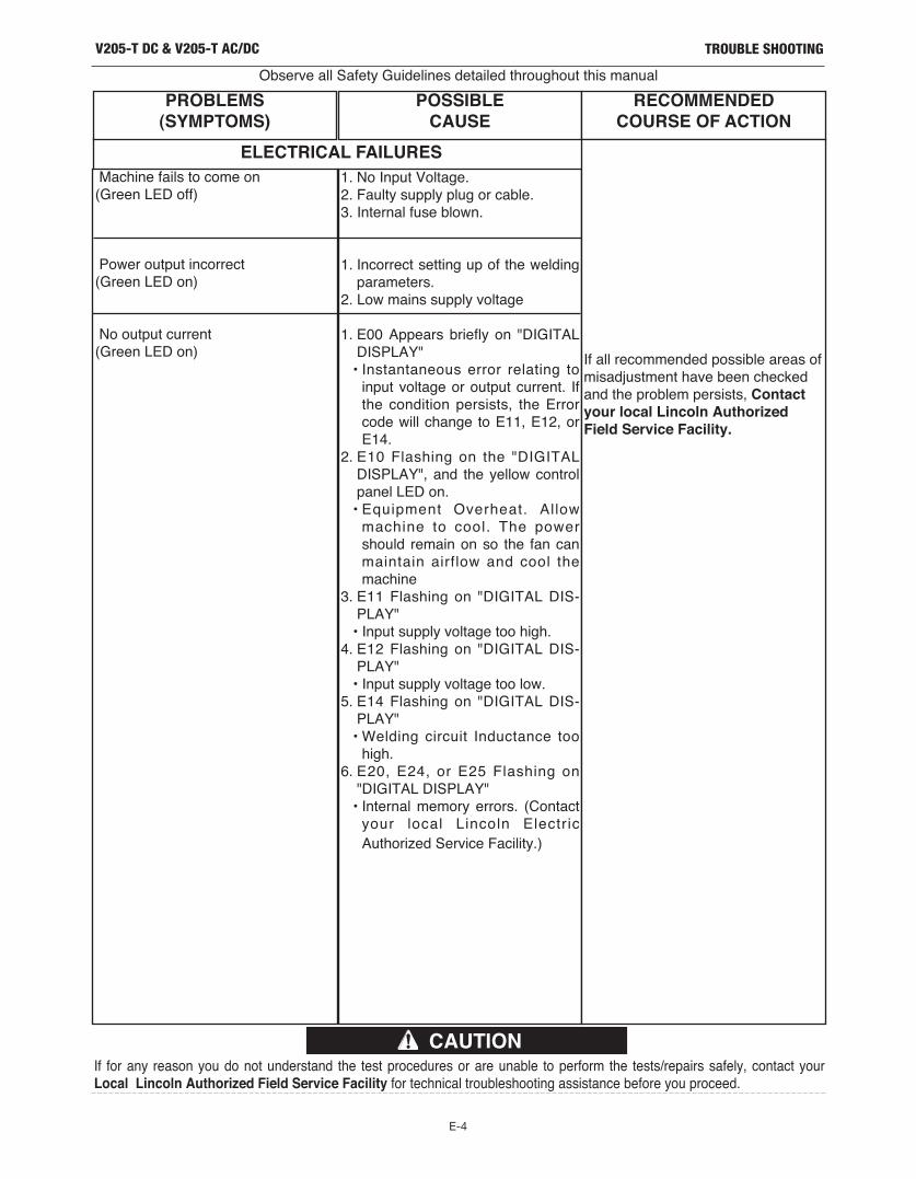
E-4
TROUBLE SHOOTING
Observe all Safety Guidelines detailed throughout this manual
If for any reason you do not understand the test procedures or are unable to perform the tests/repairs safely, contact yourLocal Lincoln Authorized Field Service Facility for technical troubleshooting assistance before you proceed.
CAUTION
V205-T DC & V205-T AC/DC
PROBLEMS(SYMPTOMS)
POSSIBLECAUSE
RECOMMENDEDCOURSE OF ACTION
Machine fails to come on(Green LED off)
Power output incorrect(Green LED on)
No output current(Green LED on)
1. No Input Voltage.2. Faulty supply plug or cable.3. Internal fuse blown.
1. Incorrect setting up of the weldingparameters.
2. Low mains supply voltage
1. E00 Appears briefly on "DIGITALDISPLAY"• Instantaneous error relating to
input voltage or output current. Ifthe condition persists, the Errorcode will change to E11, E12, orE14.
2. E10 Flashing on the "DIGITALDISPLAY", and the yellow controlpanel LED on.• Equipment Overheat. Allow
machine to cool. The powershould remain on so the fan canmaintain airflow and cool themachine
3. E11 Flashing on "DIGITAL DIS-PLAY"• Input supply voltage too high.
4. E12 Flashing on "DIGITAL DIS-PLAY"• Input supply voltage too low.
5. E14 Flashing on "DIGITAL DIS-PLAY"• Welding circuit Inductance too
high.6. E20, E24, or E25 Flashing on
"DIGITAL DISPLAY"• Internal memory errors. (Contact
your local Lincoln Electric
Authorized Service Facility.)
If all recommended possible areas ofmisadjustment have been checkedand the problem persists, Contactyour local Lincoln AuthorizedField Service Facility.
ELECTRICAL FAILURES

F-1
DIAGRAMSV205-T DC & V205-T AC/DC
NO
TE
: T
his
dia
gra
m is for
refe
rence o
nly
. It m
ay n
ot be a
ccura
te for
all
machin
es c
overe
d b
y this
manual. T
he s
pecific
dia
gra
m for
a p
art
icula
r code is p
aste
d insid
e the
machin
e o
n o
ne o
f th
e e
nclo
sure
panels
. If th
e d
iagra
m is ille
gib
le, w
rite
to the S
erv
ice D
epart
ment fo
r a r
epla
cem
ent. G
ive the e
quip
ment code n
um
ber.
V205-T
DC
WIR
ING
DIA
GR
AM
FO
R 1
1426

F-2
DIAGRAMSV205-T DC & V205-T AC/DC
NO
TE
: T
his
dia
gra
m is for
refe
rence o
nly
. It m
ay n
ot be a
ccura
te for
all
machin
es c
overe
d b
y this
manual. T
he s
pecific
dia
gra
m for
a p
art
icula
r code is p
aste
d insid
e the
machin
e o
n o
ne o
f th
e e
nclo
sure
panels
. If th
e d
iagra
m is ille
gib
le, w
rite
to the S
erv
ice D
epart
ment fo
r a r
epla
cem
ent. G
ive the e
quip
ment code n
um
ber.
V2
05
-T A
C/D
C W
IRIN
G D
IAG
RA
M F
OR
11
43
0

F-3
NOTESV205-T DC & V205-T AC/DC

Customer assistanCe PoliCy
The business of The Lincoln Electric Company is manufacturing andselling high quality welding equipment, consumables, and cuttingequipment. Our challenge is to meet the needs of our customers andto exceed their expectations. On occasion, purchasers may askLincoln Electric for advice or information about their use of ourproducts. We respond to our customers based on the best informationin our possession at that time. Lincoln Electric is not in a position towarrant or guarantee such advice, and assumes no liability, withrespect to such information or advice. We expressly disclaim anywarranty of any kind, including any warranty of fitness for anycustomer’s particular purpose, with respect to such information oradvice. As a matter of practical consideration, we also cannot assumeany responsibility for updating or correcting any such information oradvice once it has been given, nor does the provision of informationor advice create, expand or alter any warranty with respect to the saleof our products.
Lincoln Electric is a responsive manufacturer, but the selection anduse of specific products sold by Lincoln Electric is solely within thecontrol of, and remains the sole responsibility of the customer. Manyvariables beyond the control of Lincoln Electric affect the resultsobtained in applying these types of fabrication methods and servicerequirements.
Subject to Change – This information is accurate to the best of ourknowledge at the time of printing. Please refer to www.lincolnelectric.com for any updated information.