Inventor Design Exercise 2 - F1 CAR
62
Autodesk Inventor Design Exercise 2: F1 Team Challenge Car Developed by Tim Varner – Synergis Technologies © Tim Varner - 2004
-
Upload
kanfeicheng -
Category
Documents
-
view
229 -
download
0
Transcript of Inventor Design Exercise 2 - F1 CAR

8/12/2019 Inventor Design Exercise 2 - F1 CAR
http://slidepdf.com/reader/full/inventor-design-exercise-2-f1-car 1/62
Autodesk Inventor Design Exercise 2:
F1 Team Challenge Car Developed by Tim Varner – Synergis Technologies
© Tim Varner - 2004

8/12/2019 Inventor Design Exercise 2 - F1 CAR
http://slidepdf.com/reader/full/inventor-design-exercise-2-f1-car 2/62
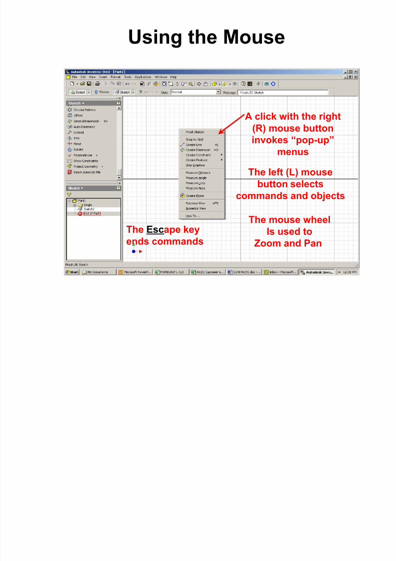
The Inventor User Interface
Graphics WindowDisplays your model
Model BrowserRecords a history ofthe operations you
have performed
Command PanelLists the commands thatare currently available in
2D Sketch or Part features mode
Standard
Toolbar
Message BarPrompts the user
for input(similar to the Command
Line in AutoCAD)

8/12/2019 Inventor Design Exercise 2 - F1 CAR
http://slidepdf.com/reader/full/inventor-design-exercise-2-f1-car 3/62
The Inventor User Interface
Dialog Boxes open whenInformation needs to be
Input by the user

8/12/2019 Inventor Design Exercise 2 - F1 CAR
http://slidepdf.com/reader/full/inventor-design-exercise-2-f1-car 4/62
More about the User Interface
Left clicking on a down arrownext to a command will opena pull-down menu with additional
options
Slider bar – used forscrolling up and down
Fly out tabs show the user thecommand before selection
8/12/2019 Inventor Design Exercise 2 - F1 CAR
http://slidepdf.com/reader/full/inventor-design-exercise-2-f1-car 5/62

8/12/2019 Inventor Design Exercise 2 - F1 CAR
http://slidepdf.com/reader/full/inventor-design-exercise-2-f1-car 6/62
Step 1. – Launch Autodesk Inventor by double (L) clicking the Inventor Icon on the Windows desktop.
Step 2. – (L) click on Open. Your Instructor will tell you which directory to “ Look in ”. (L) click on the directorythen (L) click on the file F1Blank.ipt . (L) click on Open .

8/12/2019 Inventor Design Exercise 2 - F1 CAR
http://slidepdf.com/reader/full/inventor-design-exercise-2-f1-car 7/62
Step 3. – (L) click on the Rotate button in the Standard Toolbar and a “free rotate target” will appear on thescreen. Move the cursor inside the target, press and hold the left mouse button while moving the mouse.Notice how the view rotates. Next, move the cursor just outside the target; press and hold the left mousebutton while moving the mouse. Notice how the view rotates.
Step 3
Free Rotatetarget
Rotate button
8/12/2019 Inventor Design Exercise 2 - F1 CAR
http://slidepdf.com/reader/full/inventor-design-exercise-2-f1-car 8/62

8/12/2019 Inventor Design Exercise 2 - F1 CAR
http://slidepdf.com/reader/full/inventor-design-exercise-2-f1-car 9/62
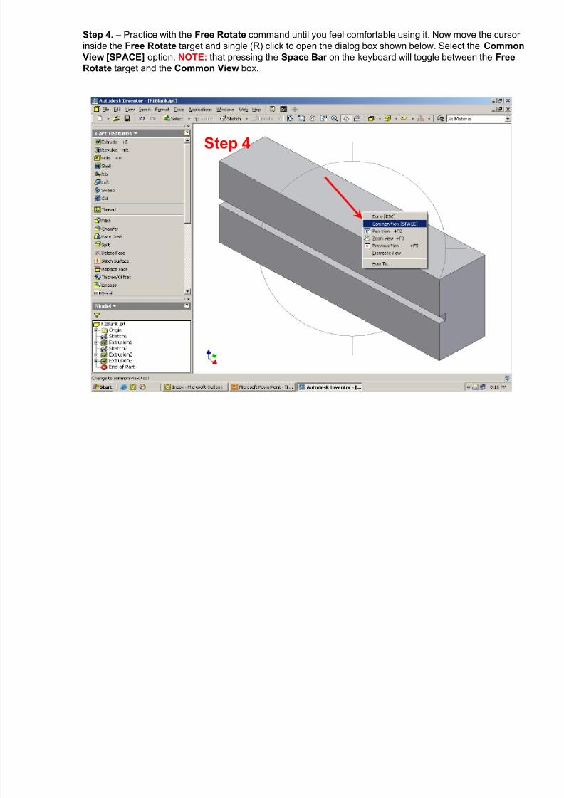
Step 5. – When the Common View command is selected, the Free Rotate target disappears and theCommon View box is displayed. The green arrows indicate the direction from which your model will beviewed. As you move the cursor over the green arrows with the mouse they highlight. When the arrows arehighlighted and selected with a (L) click, the view changes according to the direction the selected arrow waspointing. Practice with the Common View rotation command until you feel comfortable using it.
Common View box
Step 5

8/12/2019 Inventor Design Exercise 2 - F1 CAR
http://slidepdf.com/reader/full/inventor-design-exercise-2-f1-car 10/62
Step 6. – Using a combination of Free Rotate and Common View , Rotate the F1 Blank until you arelooking directly at the TOP surface (as shown below) with the hole for the CO2 cartridge to the left. Check tobe sure the hole is to the left by toggling the display between Shaded Display and Wireframe Display withthe Shaded Display icons.
Shaded Display icons
Step 6
8/12/2019 Inventor Design Exercise 2 - F1 CAR
http://slidepdf.com/reader/full/inventor-design-exercise-2-f1-car 11/62
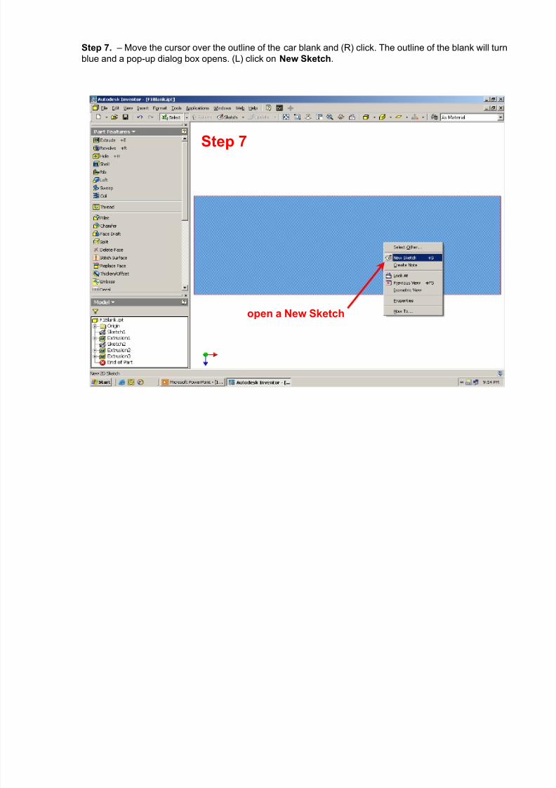
Step 7. – Move the cursor over the outline of the car blank and (R) click. The outline of the blank will turnblue and a pop-up dialog box opens. (L) click on New Sketch .
open a New Sketch
Step 7
8/12/2019 Inventor Design Exercise 2 - F1 CAR
http://slidepdf.com/reader/full/inventor-design-exercise-2-f1-car 12/62
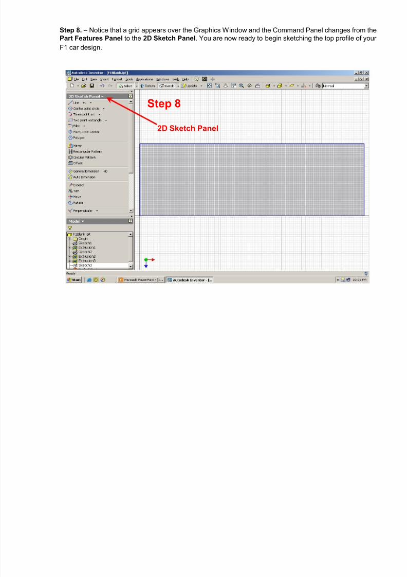
Step 8. – Notice that a grid appears over the Graphics Window and the Command Panel changes from thePart Features Panel to the 2D Sketch Panel . You are now ready to begin sketching the top profile of yourF1 car design.
Step 8
2D Sketch Panel

8/12/2019 Inventor Design Exercise 2 - F1 CAR
http://slidepdf.com/reader/full/inventor-design-exercise-2-f1-car 13/62
NOTE: – When sketching with the Line command, a (L) click will start a line (point 1 below); move themouse and (L) click again to locate the end point of a line (point 2 below). To draw arcs while in the Line command, (L) click and hold the mouse button down (point 2 below) and move the mouse to trace an arc.When you have traced the desired arc, release the left mouse button (point 3 below). When finished with theline command, (R) click and select Done from the pop-up menu.
Line command
1 2
3

8/12/2019 Inventor Design Exercise 2 - F1 CAR
http://slidepdf.com/reader/full/inventor-design-exercise-2-f1-car 14/62
Design Alternative: – You can also sketch with splines. Splines are free-formed curves. To use the Spline command, (L) click on the down arrow beside the Line command then (L) click on Spline . When you haveplaced the last point of the spline, (R) click and select Continue from the pop-up menu with a (L) click.Practice with the Line and Spline commands before going to the next step.
Spline command
1 23 4 5 6
78
9
Spline

8/12/2019 Inventor Design Exercise 2 - F1 CAR
http://slidepdf.com/reader/full/inventor-design-exercise-2-f1-car 15/62
Sketching hint: When sketching, be sure that the shape you are sketching forms a closed profile . If thereare open profiles or self intersecting profiles in your sketch, t hey wi l l no t ex t rude ! These conditions canbe corrected by using the Extend command and/or the Trim command.
Sketching hints:
Open profile
Close by using theExtend command
Extend
Close by using theTrim command
Self intersecting profile
These conditions must be corrected before continuing.
Trim
Correct these conditions with the Extend or Trim commands

8/12/2019 Inventor Design Exercise 2 - F1 CAR
http://slidepdf.com/reader/full/inventor-design-exercise-2-f1-car 16/62
Step 9. - From the 2D Sketch Panel , select the Line command with a single (L) click. Draw the roughsketch shown below. Notice that the cursor turns to a yellow dot, and as you move the dot along the outlineof the sketch, it will turn green at the end points and mid-points of the lines. Once a mid-point or end pointhas been found, construction lines will project from the yellow dot as you move the cursor horizontally orvertically. Don’t worry about exact dimensions. When placing your points, follow the order below and be surethat your sketch forms a closed profile. REMEMBER - If the profile is not closed it will not extrude .
Step 4Step 9
12
3 4 5 6 78 9 10
11
8/12/2019 Inventor Design Exercise 2 - F1 CAR
http://slidepdf.com/reader/full/inventor-design-exercise-2-f1-car 17/62
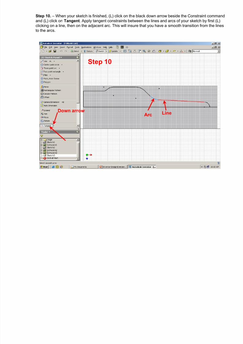
Step 10. – When your sketch is finished, (L) click on the black down arrow beside the Constraint commandand (L) click on Tangent . Apply tangent constraints between the lines and arcs of your sketch by first (L)clicking on a line, then on the adjacent arc. This will insure that you have a smooth transition from the linesto the arcs.
Step 10
Arc LineDown arrow

8/12/2019 Inventor Design Exercise 2 - F1 CAR
http://slidepdf.com/reader/full/inventor-design-exercise-2-f1-car 18/62
Step 11. – (L) click on the Mirror command. Select each of the lines in your sketch by (L) clicking on themindividually (holding the Shift key down will allow you to select multiple lines) or by windowing the sketch.Note that as you select the lines they highlight. DO NOT select the horizontal center line . Be careful toselect ALL of the lines in your sketch (in blue below) so that, when they are mirrored, they form a CLOSEDPROFILE .
Step 11

8/12/2019 Inventor Design Exercise 2 - F1 CAR
http://slidepdf.com/reader/full/inventor-design-exercise-2-f1-car 19/62
Step 12. – After all of the sketch lines have been selected (highlighted), (L) click on the Mirror line button and select the horizontal line (highlighted in red below). (L) click on Apply to complete the mirror image,then click on Done to end the Mirror command.
Step 12

8/12/2019 Inventor Design Exercise 2 - F1 CAR
http://slidepdf.com/reader/full/inventor-design-exercise-2-f1-car 20/62
Step 13. – (L) click on the 2D Sketch Panel and switch to the Part Features panel. Then (L) click onExtrude to open the Extrude dialog box.
Step 13

8/12/2019 Inventor Design Exercise 2 - F1 CAR
http://slidepdf.com/reader/full/inventor-design-exercise-2-f1-car 21/62
Step 14. – First select the Profile by moving your cursor over the sketch until the top half of the profilehighlights and (L) clicking. Hold the Shift key , move the cursor over the bottom half of the sketch and (L)click when the bottom half of the profile highlights. NOTE: - if you are unable to select both profiles(highlighted in blue below), and a red cross is displayed in the Extrude dialog box, this indicates that thereis an open profile in your sketch – return to the sketch mode and correct the problem. Next (L) click on theCut button and set the Extents Distance to All. To finish making the cut extrusion, (L) click on OK .
Step 14Profile
Cut All
A red cross willdisplay here if there is
an open or self Intersectingprofile in your sketch.
8/12/2019 Inventor Design Exercise 2 - F1 CAR
http://slidepdf.com/reader/full/inventor-design-exercise-2-f1-car 22/62
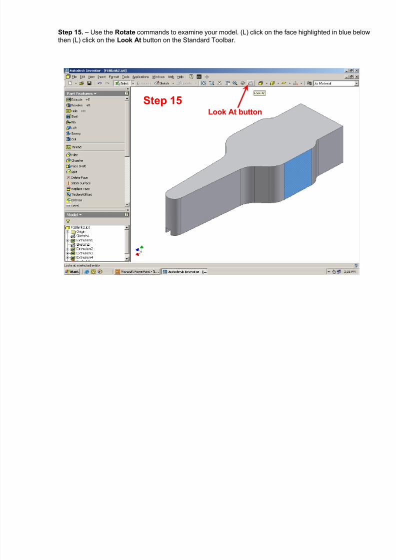
Step 15. – Use the Rotate commands to examine your model. (L) click on the face highlighted in blue belowthen (L) click on the Look At button on the Standard Toolbar.
Step 15Look At button
8/12/2019 Inventor Design Exercise 2 - F1 CAR
http://slidepdf.com/reader/full/inventor-design-exercise-2-f1-car 23/62
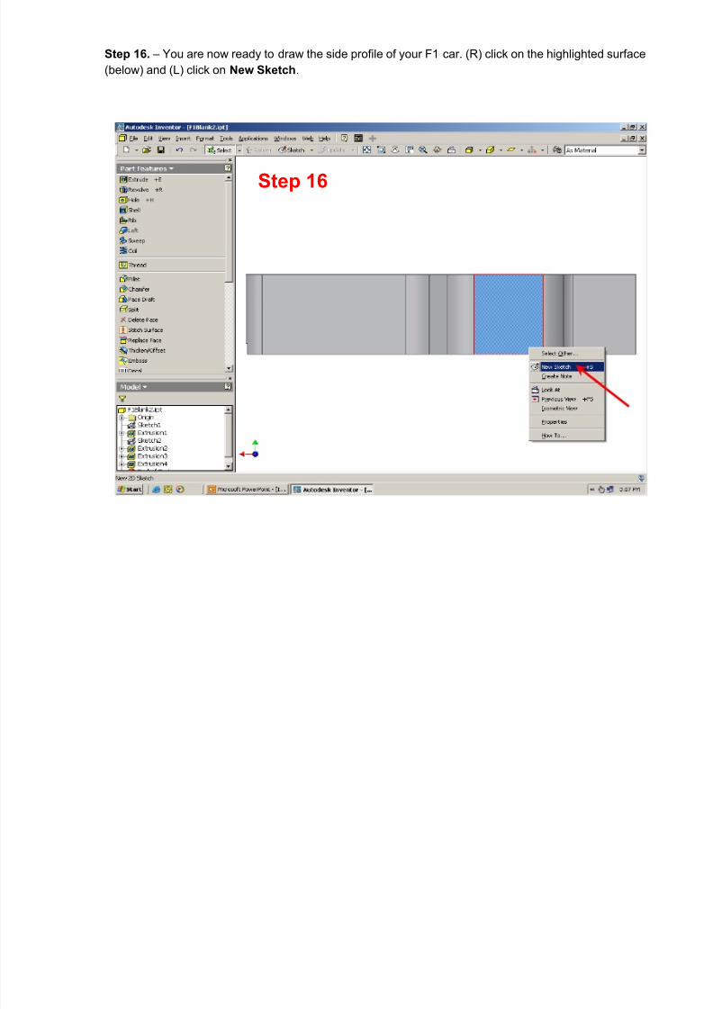
Step 16. – You are now ready to draw the side profile of your F1 car. (R) click on the highlighted surface(below) and (L) click on New Sketch .
Step 16

8/12/2019 Inventor Design Exercise 2 - F1 CAR
http://slidepdf.com/reader/full/inventor-design-exercise-2-f1-car 24/62
Step 17. – Notice that a new sketch has been opened and 4 lines from our model have been automaticallyprojected onto our sketch plane . For this step, these 4 lines must be deleted.
Step 17

8/12/2019 Inventor Design Exercise 2 - F1 CAR
http://slidepdf.com/reader/full/inventor-design-exercise-2-f1-car 25/62
Step 18. – Window the 4 lines by (L) clicking at 1 (below) and, while holding the (L) mouse button, drag themouse to 2 and release the button. NOTICE that all 4 lines will highlight. (R) click and select Delete from thepop-up window.
Step 18
1
2
8/12/2019 Inventor Design Exercise 2 - F1 CAR
http://slidepdf.com/reader/full/inventor-design-exercise-2-f1-car 26/62
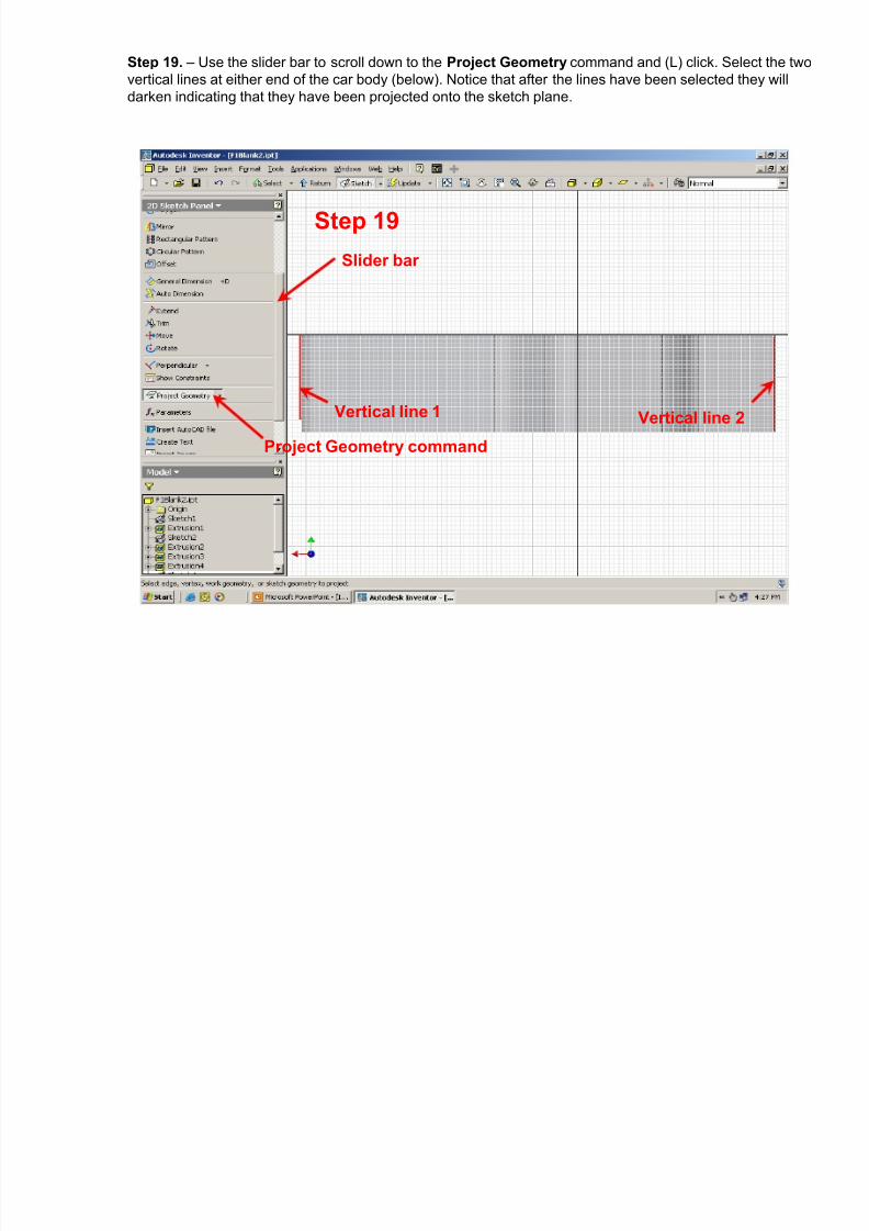
Step 19. – Use the slider bar to scroll down to the Project Geometry command and (L) click. Select the twovertical lines at either end of the car body (below). Notice that after the lines have been selected they willdarken indicating that they have been projected onto the sketch plane.
Step 19
Slider bar
Vertical line 1 Vertical line 2
Project Geometry command

8/12/2019 Inventor Design Exercise 2 - F1 CAR
http://slidepdf.com/reader/full/inventor-design-exercise-2-f1-car 27/62
Step 20. – Select the Line command and draw line 1-2-3 and then line 4-5 . Be careful to lock on to the endsof the vertical lines that were projected in the last step so that they form a CLOSED PROFILE . The cursorwill turn from a yellow dot to a green dot when you have locked on to the end points of the lines.
Step 21Step 20
12
3
45

8/12/2019 Inventor Design Exercise 2 - F1 CAR
http://slidepdf.com/reader/full/inventor-design-exercise-2-f1-car 28/62
Step 21. – Switch to the Wireframe Display mode from the Standard Toolbar as shown below. This willmake it easier to sketch the side profile. Be careful not to sketch over top of the hole for the CO 2 cartridge .
Step 21
Hole for the CO 2
cartridge

8/12/2019 Inventor Design Exercise 2 - F1 CAR
http://slidepdf.com/reader/full/inventor-design-exercise-2-f1-car 29/62
Step 22. – Using the Line command, sketch a profile similar to the one below. Be sure that your sketchforms a closed profile with no self intersecting lines.
Step 22

8/12/2019 Inventor Design Exercise 2 - F1 CAR
http://slidepdf.com/reader/full/inventor-design-exercise-2-f1-car 30/62
Step 23. – Switch to the Part Features command panel. (L) click on Extrude and (L) click again on theprofile shown in blue below. (L) click on the Cut button and set the distance under Extents to All. (L) clickon OK to complete the extrusion. NOTE: if a red cross is displayed in the Extrude dialog box, this indicatesthat there is an open profile in your sketch – return to the sketch mode and correct the problem.
Step 23

8/12/2019 Inventor Design Exercise 2 - F1 CAR
http://slidepdf.com/reader/full/inventor-design-exercise-2-f1-car 31/62
Step 24. – From the Standard Toolbar, switch the display back to Shaded Display . Use the Rotate commands to examine your model.
Step 24

8/12/2019 Inventor Design Exercise 2 - F1 CAR
http://slidepdf.com/reader/full/inventor-design-exercise-2-f1-car 32/62
Step 25. – Use the Rotate , Look At and Zoom All commands in the Standard Toolbar to rotate your modelso you are looking directly into the back end of the car. Move the cursor over the model, (R) click to selectthe surface highlighted below and select New Sketch .
Step 25 Zoom All Rotate Look At

8/12/2019 Inventor Design Exercise 2 - F1 CAR
http://slidepdf.com/reader/full/inventor-design-exercise-2-f1-car 33/62
Step 26. – Change the display to Wireframe . Scroll the slider bar down and select the Project Geometry command. (L) click on the line highlighted in red below.
Step 26Wire Frame display
Project
Geometry

8/12/2019 Inventor Design Exercise 2 - F1 CAR
http://slidepdf.com/reader/full/inventor-design-exercise-2-f1-car 34/62
Step 27. – Use the Line command to sketch the lines 1-2-3-4-5-6 and lines 7-8-9-10 .
12
3 4
56
Step 27
7
8 9
10

8/12/2019 Inventor Design Exercise 2 - F1 CAR
http://slidepdf.com/reader/full/inventor-design-exercise-2-f1-car 35/62
Step 28. – From the 2D Sketch Panel, scroll down with the slider bar to the Constraint command and selectTangent . (L) click on the arc and the line indicated below. NOTE: be sure that the circle and the arc areconcentric (have the same center point). If not, also apply a Concentric constraint to the circle and arc.
Step 28
Tangent Concentric

8/12/2019 Inventor Design Exercise 2 - F1 CAR
http://slidepdf.com/reader/full/inventor-design-exercise-2-f1-car 36/62
Step 29. – Switch to the Part Features command panel, and (L) click on Extrude . (L) click on the Profile highlighted below, select the Cut option and set the distance to All. (L) click on OK to complete the cutextrusion.
Step 29
Cut

8/12/2019 Inventor Design Exercise 2 - F1 CAR
http://slidepdf.com/reader/full/inventor-design-exercise-2-f1-car 37/62
Step 30. – Switch back to the Shaded Display and examine your design. (R) click on the surfacehighlighted below and select New Sketch .
Step 30Shaded display
8/12/2019 Inventor Design Exercise 2 - F1 CAR
http://slidepdf.com/reader/full/inventor-design-exercise-2-f1-car 38/62
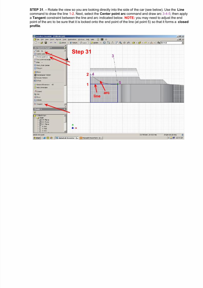
STEP 31 . – Rotate the view so you are looking directly into the side of the car (see below). Use the Line command to draw the line 1-2 . Next, select the Center point arc command and draw arc 3-4-5 ; then applya Tangent constraint between the line and arc indicated below. NOTE: you may need to adjust the endpoint of the arc to be sure that it is locked onto the end point of the line (at point 5) so that it forms a closedprofile .
Step 31
1
2
3
4
5
linearc

8/12/2019 Inventor Design Exercise 2 - F1 CAR
http://slidepdf.com/reader/full/inventor-design-exercise-2-f1-car 39/62
Step 32. – Switch from the 2D Sketch Panel to the Part Features panel and select Extrude . Select theProfile highlighted below with a (L) click, be sure the Join button is depressed and set the Distance to ToNext . Click on OK to complete the join extrusion.
Step 32
Join

8/12/2019 Inventor Design Exercise 2 - F1 CAR
http://slidepdf.com/reader/full/inventor-design-exercise-2-f1-car 40/62
Step 33. – Rotate your model to the isometric view shown below. Use the slider bar to scroll down the PartFeatures panel to the Mirror Feature command. (L) click on the arc feature that was extruded in theprevious step.
Step 33
Arc feature

8/12/2019 Inventor Design Exercise 2 - F1 CAR
http://slidepdf.com/reader/full/inventor-design-exercise-2-f1-car 41/62
Step 34. – (L) click on the Mirror Plane button and, from the Model Browser, (L) click on the “ +” sign to theleft of Origin . Then, (L) click on XY Plane . NOTE: that the different planes will highlight in the graphicswindow as you move the cursor over them. Finish the Mirror Feature by (L) clicking on OK .
Step 34

8/12/2019 Inventor Design Exercise 2 - F1 CAR
http://slidepdf.com/reader/full/inventor-design-exercise-2-f1-car 42/62
Step 35. – Rotate back to the side view of the car and select the Sketch command from the standardtoolbar. In the Model browser, select the XY Plane to open a new sketch
Step 35 Sketch
8/12/2019 Inventor Design Exercise 2 - F1 CAR
http://slidepdf.com/reader/full/inventor-design-exercise-2-f1-car 43/62
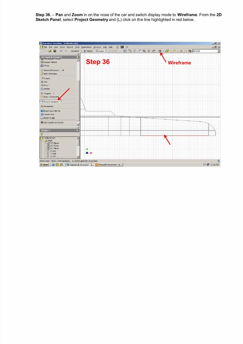
Step 36. – Pan and Zoom in on the nose of the car and switch display mode to Wireframe . From the 2DSketch Panel , select Project Geometry and (L) click on the line highlighted in red below.
Step 36 Wireframe

8/12/2019 Inventor Design Exercise 2 - F1 CAR
http://slidepdf.com/reader/full/inventor-design-exercise-2-f1-car 44/62
Step 37. – Use the Line command to draw lines 1-2-3-4 . Use the Center point arc command to draw arc 5-6-7 . Apply a Tangent constraint between the line and arc shown below. NOTE: be sure that the end pointsof the arc are locked onto the endpoints of the lines so that they form a closed profile .
Step 37
12
3 4
5
6
line arc
7

8/12/2019 Inventor Design Exercise 2 - F1 CAR
http://slidepdf.com/reader/full/inventor-design-exercise-2-f1-car 45/62
Step 38. – Rotate the display to an isometric view. Switch from the 2D Sketch Panel to the Part Features panel and select Extrude . (L) click on the Profile highlighted in blue below. Be sure the Join button isdepressed, set the Distance to 70 and (L) click on the Mid-Plane extrusion button. Check to be sure thatthe extrusion preview (highlighted in green) looks similar to what is shown below. If so, (L) click on OK .
Step 37
Tangent constraint
Step 38
Mid-Planeextrusion
button
Join

8/12/2019 Inventor Design Exercise 2 - F1 CAR
http://slidepdf.com/reader/full/inventor-design-exercise-2-f1-car 46/62
Step 39. – Switch the display back to Shaded . (R) click on the surface highlighted in blue, below, and (L)click on New Sketch .
Step 39 Shaded

8/12/2019 Inventor Design Exercise 2 - F1 CAR
http://slidepdf.com/reader/full/inventor-design-exercise-2-f1-car 47/62
Step 40. – (L) click on the Look At button on the Standard Toolbar and (L) click on the surface highlightedbelow.
Step 40Look at

8/12/2019 Inventor Design Exercise 2 - F1 CAR
http://slidepdf.com/reader/full/inventor-design-exercise-2-f1-car 48/62
Step 41. – Zoom in on the cockpit area of the car and use the Line command to draw the sketch shownbelow.
Step 41
Sketch forcockpit
Step 42. – On the 2D Sketch Panel , (L) click on the General Dimension command. (L) click on the 2 lines

8/12/2019 Inventor Design Exercise 2 - F1 CAR
http://slidepdf.com/reader/full/inventor-design-exercise-2-f1-car 49/62
Step 42. On the 2D Sketch Panel , (L) click on the General Dimension command. (L) click on the 2 linesyou want to dimension then move your cursor to where you want to place the dimension and (L) click again.This will open the Edit Dimension dialog box and display the actual dimension. From the keyboard, type inthe correct dimension ( 4) and press the Enter key or (L) click on the green check mark in the EditDimension dialog box. Notice how the lines move according to the dimension you entered. This is calledparamet r i c d im ens ion ing .
Step 42
(L) click Enter the correctdimension (4)then press the
Enter key - or (L)click on the green
Check Box.
(L) Click to placedimension
Step 43 Continue using the General Dimension command to add the dimensions shown below NOTE:

8/12/2019 Inventor Design Exercise 2 - F1 CAR
http://slidepdf.com/reader/full/inventor-design-exercise-2-f1-car 50/62
Step 43. – Continue using the General Dimension command to add the dimensions shown below. NOTE: after dimensions have been placed on a sketch, they can be easily changed at any time by double (L)clicking on the dimension you want to change. This will re-open the General Dimension dialog box. Typethe new dimension and press the Enter key or (L) click on the green check in the Edit Dimension dialogbox. Your sketch will automatically re-size to the new dimension. Try changing dimensions before going onto the next step.
Step 43
(2)
(4)
(4)

8/12/2019 Inventor Design Exercise 2 - F1 CAR
http://slidepdf.com/reader/full/inventor-design-exercise-2-f1-car 51/62
Step 44. – Rotate the view similar to that shown below. Switch from the 2D Sketch Panel to the PartFeatures panel. (L) click on Extrude . (L) click on the Profile highlighted in blue, (L) click on the Cut buttonand set the Distance to 10 . Complete the Cut extrusion for the cockpit by (L) clicking on the OK button.
Step 44
Step 45. – This completes the basic design of your F1 car. To finish the design process, you will need to

8/12/2019 Inventor Design Exercise 2 - F1 CAR
http://slidepdf.com/reader/full/inventor-design-exercise-2-f1-car 52/62
p p g y g p , ysmooth or round the sharp edges with the Fillet command. On the Part Features panel, (L) click on Fillet .The Fillet dialog box will open. Under Radius , type in the number 7. (L) click on the edge shown below (thered arcs give a preview of what the fillet will look like) and (L) click on the OK button. NOTE: that multipleedges that are to have the same radius fillets can all be selected at the same time by (L) clicking on them.
Step 45Edge to be
filleted

8/12/2019 Inventor Design Exercise 2 - F1 CAR
http://slidepdf.com/reader/full/inventor-design-exercise-2-f1-car 53/62
Step 46. – (L) click on the Fillet command again, set the fillet radius to 6 and select the 2 edges shownbelow. (L) click on OK to complete the fillets.
Step 46

8/12/2019 Inventor Design Exercise 2 - F1 CAR
http://slidepdf.com/reader/full/inventor-design-exercise-2-f1-car 54/62
Step 47. – Select the Fillet command again, set the radius to .1 and select the 2 edges highlighted in bluebelow. (L) click on OK .
Step 47
S 48 S l h Fill d h di 3 d l h 2 d h b l NOTE

8/12/2019 Inventor Design Exercise 2 - F1 CAR
http://slidepdf.com/reader/full/inventor-design-exercise-2-f1-car 55/62
Step 48. – Select the Fillet command, set the radius to 3 and select the 2 edges shown below. NOTE: youwill have to use the Free Rotate command, while in the middle of the Fillet command, in order to selectboth edges. Select the first edge, (L) click on the Free Rotate command and rotate the view until you cansee the second edge, press the Escape key to exit the Free Rotate command, then select the secondedge. (L) click on OK .
Step 48Free Rotate
8/12/2019 Inventor Design Exercise 2 - F1 CAR
http://slidepdf.com/reader/full/inventor-design-exercise-2-f1-car 56/62
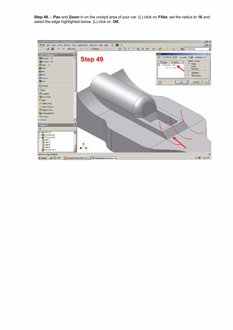
Step 49. – Pan and Zoom in on the cockpit area of your car. (L) click on Fillet , set the radius to 16 andselect the edge highlighted below. (L) click on OK .
Step 49
Step 50. – Continue filleting the cockpit area. If you select a fillet radius that is too large or can not be

8/12/2019 Inventor Design Exercise 2 - F1 CAR
http://slidepdf.com/reader/full/inventor-design-exercise-2-f1-car 57/62
Step 50. Continue filleting the cockpit area. If you select a fillet radius that is too large or can not besuccessfully cut, the Edit Fillet Feature dialog box will open, the problem will highlight in the graphicswindow, and an explanation of the problem and a suggested solution will be given. In this case, the radiusspecified was too large . (L) click on the Edit button to re-open the Fillet dialog box and enter a smallerfillet radius.
Step 49
Axel holeshighlighted
Direction ofCut arrow
Step 50
Problemhighlighted
In green
S 51 NOTE f f h b l d i b il di d i b i h M d l

8/12/2019 Inventor Design Exercise 2 - F1 CAR
http://slidepdf.com/reader/full/inventor-design-exercise-2-f1-car 58/62
Step 51. – NOTE: after a feature has been placed, it can be easily edited, at any time, by using the ModelBrowser . Notice that as you move the cursor over each feature in the Model browser , that feature willhighlight on your model in the graphics window. When the feature you want to edit highlights, (R) click onthat feature in the Model Browser and then (L) click on Edit Feature . The dialog box for that feature willopen and the new values can be entered. (L) clicking on the OK button will update the model.
Step 51
ModelBrowser
Features

8/12/2019 Inventor Design Exercise 2 - F1 CAR
http://slidepdf.com/reader/full/inventor-design-exercise-2-f1-car 59/62
Step 52. – Continue using the Fillet command until you have a design that you are happy with. Yourfinished F1 car design should look something like the one below.
Step 52

8/12/2019 Inventor Design Exercise 2 - F1 CAR
http://slidepdf.com/reader/full/inventor-design-exercise-2-f1-car 60/62
Step 53. – From the Standard Toolbar , (L) click on the File command, then (L) click on Save Copy As .The Save Copy As dialog box will open.
Step 53
S 54 I h S i b l h f ld h fil i I h Fil b

8/12/2019 Inventor Design Exercise 2 - F1 CAR
http://slidepdf.com/reader/full/inventor-design-exercise-2-f1-car 61/62
Step 54. – In the Save in: box, select the folder that you want to save your file in. In the File name: box,type in the name you want to use for your F1 model. NOTE: that the Save as type: will default to Part Files(*.ipt) . (L) click on Save .
Step 54
Step 55. – From the Standard Toolbar (L) click on the File option again, then (L) click on Save Copy As toopen the Save Copy As: dialog box. In the Save In box, enter the folder where you want to save your

8/12/2019 Inventor Design Exercise 2 - F1 CAR
http://slidepdf.com/reader/full/inventor-design-exercise-2-f1-car 62/62
p py g , y ymodel. In the File name: box, type in the same name used in the previous step, then click on the blackdown arrow to the right of the Save as type: box . (L) click on the STL Files (*.stl) option. (L) click on Save .The STL file format is accepted by all of the popular CAM software programs that run CNC machine tools.This .stl version of your F1 model is what will be used by the CAM software to produce your F1 car on aCNC mill or router.
Step 55
STL Files (*.stl)
Down arrow