Introduction · Web viewEach radar sensor shall measure range, radial speed, angle, reflectivity,...
7
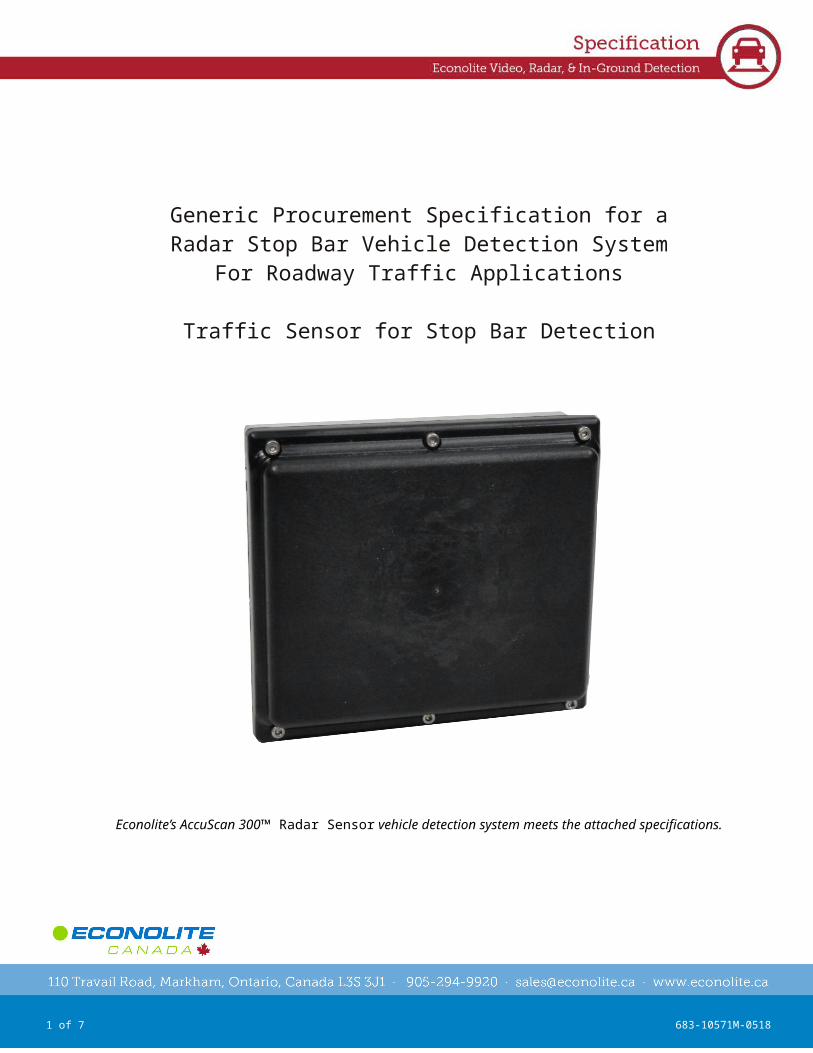
REV:0 1 of 7 683-10571M-0518 Generic Procurement Specification for a Radar Stop Bar Vehicle Detection System For Roadway Traffic Applications Traffic Sensor for Stop Bar Detection Econolite’s AccuScan 300™ Radar Sensor vehicle detection system meets the attached specifications.
Transcript of Introduction · Web viewEach radar sensor shall measure range, radial speed, angle, reflectivity,...
REV:01 of 5 683-10571M-0518
Generic Procurement Specification for a Radar Stop Bar Vehicle Detection System
For Roadway Traffic Applications
Traffic Sensor for Stop Bar Detection
Econolite’s AccuScan 300™ Radar Sensor vehicle detection system meets the attached specifications.

REV:02 of 5 683-10571M-0518
1.0 Radar Advance Detection - GeneralThis specification sets forth the minimum requirements for purchase and installation of an aboveground Radar Detection Device (RDD) system for a real-time, stop bar vehicle-detection system that monitors vehicles at signalized intersections using forward-fire Radar processing techniques and provides detector outputs to a traffic controller or similar device. This system shall be easily configurable and expandable to meet traffic management applications for various intersection control strategies, during road or intersection construction at signalized intersection. The RDD shall include an interface module that includes support of a TS2 Port 1 SDLC interface along with contact closure outputs for interfacing with a traffic signal controller. The format of the interface module shall comply with the National Electrical Manufacturers Association (NEMA) shelf mount detector, NEMA type C or D detector rack, or California TEES Input File rack interface requirements.
1.1 System HardwareThe hardware shall consist of the following items provided by the system supplier:a. One or more forward-fire radar sensor assemblies consisting of the radar sensor unit, compact junction box, and mounting bracket.b. Each sensor shall include an integrated levelc. Each sensor shall include an integrated compassd. One or more cables to the sensor, consisting of two twisted pairs.e. One cabinet interface module appropriate for traffic signal controller, cabinet, and application. This may include an interface panel and power supply assembly.f. Optional laptop computer and system software for configuration and maintenance of the sensor system.
Installation and maintenance may be provided as a service. Items that may be provided by others:a. Installation of sensor and cabinet equipment.b. Interconnect branch cabling.
1.2 Configuration SoftwareThe software shall be a Windows-based tool used to configure and monitor the radar sensors. The configuration software shall allow setting up all needed site specific information like alignment and detection points to insure that the radar sensor provides accurate detection results. An online help function shall provide detailed step-by-step guidance for each configuration item.
The software shall support the configuration and maintenance of the radar sensor, including: Easy setup mode Alignment (Azimuth, Sensor Height, Elevation) 3D-Antenna Model for optimal Alignment Number Lanes Measurement Lines Trigger Points for Detection Output Control Statistic Output Multiple Sensor Setup and Configuration for Intersections Sensor Firmware Update User select interface of RS-485 or Ethernet communications

REV:03 of 5 683-10571M-0518
The software shall display various monitoring and maintenance views, including: Sensor states Objects Detection output states Statistics Data (Presence, Wrong Direction, Headway, Gap Volume, Occupancy,
Average Speed, 85th percentile Speed) per Lane, Class and Measurement Line
Once each sensor has been properly set up using the laptop computer, it shall be possible to disconnect the laptop computer. Thereafter, the sensor and interface module shall perform vehicle detection as a standalone installation.
2.0 Functional Capabilities
The sensor shall be a robust 24GHz forward-fire radar for traffic management applications.
The sensor shall operate in adverse conditions, almost unaffected by weather, and independent of sunlight, over the entire NEMA TS2 operating temperature range.
The radar antenna design shall provide a field of view (beam) that provides long range with narrow horizontal angular coverage. The field of view shall at a minimum cover up to six (6) lanes and provide vehicle detection over a range of 50 to 340 feet.
Each radar sensor shall measure range, radial speed, angle, reflectivity, and other parameters of multiple vehicles (reflectors) simultaneously. Doppler-based radial motion detection shall be at least 0.1m/s.
Filter algorithms shall track all detected reflectors (vehicles, pedestrians, and bicyclists) simultaneously over time by distinguishing individual radar reflectors with different radial speeds of greater than 0.25 m/s. It shall be possible to track a minimum of 32 and maximum of 64 objects simultaneously. Individually tracked objects shall be identified by lane of travel. Stopped objects shall remain valid in the sensor’s tracking list until they start moving again. The list of tracked objects shall be updated every 50ms.
A compact junction box shall be included with each radar sensor to allow easily connecting the sensor to field wiring. This junction box shall attach via a Binder style connector, secure with machined screws to the backside of the radar sensor and provide termination points for power, RS485 and Power-Over-Ethernet (POE) signals along with transient protection. After termination of the field cable the junction box shall mate with a connector on the rear of the radar sensor. When properly attached to the radar sensor, the junction box shall provide a weather tight seal to the back of the radar sensor.
The radar sensor shall be no larger than 95mm x 85mm x 44mm (L x H x W).
2.1 Interface to Traffic ControllerAn interface module shall be available to support a TS2 Port1/SDLC interface along with contact closure outputs to the traffic controller. It shall be possible to output the detection state directly to NEMA TS1, TS2, Type 170, Type 179, 2070, SCATS, and SCOOT controllers.

REV:04 of 5 683-10571M-0518
The interface module shall interface with up to 4 radar sensors. Communications between the interface module and each radar sensor shall be via a RS485 serial connection or user selectable Ethernet communication between the sensor and a cabinet interface or controller. The module shall also provide a 100Base T Ethernet connection that allows for interfacing with the module and connected sensor using the Configuration Software.
The interface module shall provide up to 16 open collector outputs on a front panel mounted connector. Four of these outputs shall also be available on the rear edge connector of the module. The interface module shall support the TS2 Port 1 Detector Rack BIU SDLC frames. Over the Port 1 interface the module shall be able to look like up to four Detector Rack BIUs; rack supporting 16 detector outputs each for a total of 64 virtual detector outputs.
The interface module shall support the following user interfaces: Reset button to allow reset of the interface module from the front panel Status LEDs to display wired and TS2 output detector states as well as diagnostic information such
as power, error state, and SDLC activity Relay expansion to connect to expansion modules to support detector outputs 5-16 from the front
panel Radar sensor interface via RS-485 Debug port for use by factory trained personnel SDLC Port 1 connector Ethernet Port - 100Base-TX interface USB Connector NEMA TS1/TS2 style backplane multipoint pin header
The interface module shall be 174.6mm x 114.3mm x 56.2mm (L x H x W). The interface module shall be rack mountable or available with an optional standalone shelf mount enclosure.
2.2 Interface PanelAn interface panel shall be available to allow termination of cables used to connect to each radar sensor. This panel shall be able to be easily mounted to the side wall of a typical traffic control cabinet. Termination points shall be included on the interface panel to allow easily termination the cables for up to four radar sensors. Transient protection shall be included for the RS485 signals going to each sensor. A connector shall be included for each sensor to allow connection of the RS485 signals from the interface panel to the interface module.
The interface panel shall include a 24VDC power supply to provide power to the radar sensors. This power supply shall have sufficient power capability to support a minimum of four radar sensors. Transient protection shall be included on the interface panel for the 24VDC power.
The interface panel shall be compliant with NEMA TS2 Environmental standards. Power input to the interface panel shall be in the range of 100-240 VAC, 47-63 Hz, 800mA. Output shall be 24 VDC 30W.The interface panel shall be available in two (2) configurations: aluminum back-plate or DIN rail mount. Mechanical dimensions of the interface panel shall not exceed 241.3mm x 160mm x 66.5mm (L x H x W).
REV:05 of 5 683-10571M-0518
2.3 EnvironmentalThe RDD shall operate reliably in the adverse environment typically found at an intersection and be IP67 rated. Both the RDD and interface module shall meet the environmental requirements set forth by the National Electrical Manufacturers Association (NEMA) TS2 standards. Operating temperature shall be from -34 C to +74 degrees C (-29 F to +165 F) at 0% to 95% relative humidity, non-condensing.
2.4 ElectricalThe radar sensor shall operate over the voltage range of 7 to 32 VDC and consume a maximum of 3.7 watts. Nominal input voltage shall be 24VDC. The interface module shall operate over the voltage range of 10 to 30 VDC and consume a maximum of 6 watts (not including sensor power). The interface module shall include transient protection sufficient to meet the requirements set forth in the NEMA TS2 standard. Power to the radar sensor shall be from the transient protected side of the cabinet.
3.0 Installation and Training
The supplier of the radar detection system may supervise the installation and testing of the radar detection system and computer equipment as required by the contracting agency.
Training shall be available to personnel of the contracting agency in the operation, set up, and maintenance of the radar detection system. This training shall be conducted by certified instructors and shall provide sufficient information to ensure that the end user has complete competency in system operation.
4.0 Warranty, Maintenance, and Support
The supplier shall warrant the radar detection system for a minimum of two years from the date of shipment. Ongoing software support by the supplier shall include software updates of the radar sensor, interface module, and Configuration Software applications. These updates shall be provided free of charge during the warranty period.
The manufacturer of the radar shall have a Quality System that is ISO9001 registered. Written confirmation of the ISO9001 registration shall be available from the manufacturer prior to bid acceptance if requested.
The supplier shall maintain a program for technical support and software updates following expiration of the warranty period. This program shall be available to the contracting agency in the form of a separate agreement for continuing support.