Introduction to Electrical Circuits and Lab Equipment EGR 100
17
1 Electronic Supporting Information For: 1 2 Phosphinate Stabilised ZnO and Cu Colloidal Nanocatalysts for CO 2 Hydrogenation 3 to Methanol 4 5 N.J. Brown, a J. Weiner, a K. Hellgardt, b M.S.P. Shaffer, a* C.K. Williams a* 6 a) Department of Chemistry, Imperial College London, London. SW7 2AZ 7 b) Department of Chemical Engineering, Imperial College London, London. SW7 2AZ 8 [email protected]; [email protected] 9 10 Index: 11 Page 2-5: Experimental Section 12 Pages 5-16: Figures S1-S18 and descriptons/detials of the Catalytic Activity Determinations, 13 ZnO/di(octyl)phosphinic acid determinations and Cu particle size determinations 14 Page 17: References 15 16 Electronic Supplementary Material (ESI) for Chemical Communications This journal is © The Royal Society of Chemistry 2013
Transcript of Introduction to Electrical Circuits and Lab Equipment EGR 100
1
Electronic Supporting Information For: 1 2
Phosphinate Stabilised ZnO and Cu Colloidal Nanocatalysts for CO2 Hydrogenation 3
to Methanol 4
5
N.J. Brown,a J. Weiner,
a K. Hellgardt,
b M.S.P. Shaffer,
a* C.K. Williams
a* 6
a) Department of Chemistry, Imperial College London, London. SW7 2AZ 7
b) Department of Chemical Engineering, Imperial College London, London. SW7 2AZ 8
[email protected]; [email protected] 9
10
Index: 11
Page 2-5: Experimental Section 12
Pages 5-16: Figures S1-S18 and descriptons/detials of the Catalytic Activity Determinations, 13
ZnO/di(octyl)phosphinic acid determinations and Cu particle size determinations 14
Page 17: References 15
16
Electronic Supplementary Material (ESI) for Chemical CommunicationsThis journal is © The Royal Society of Chemistry 2013
2
Experimental Section 1
Materials 2
Solvents were distilled from either sodium or CaH2 and stored under nitrogen. Unless otherwise stated, solvents were freshly 3
degassed prior to use by performing at least three freeze−pump thaw cycles. Squalane, zinc bis(stearate) and diethylzinc were 4
purchased from Aldrich. Diethyl zinc, in common with many other organometallic compounds, is pyrophoric and must be 5
handled with appropriate precautions. Copper(II) bis(stearate),1 copper bis(di octyl phosphinate),
2 zinc bis(di octyl 6
phosphinate),3 and di-octyl phosphinic acid
4 were synthesised according to a methods reported in the literature. The ternary 7
reference catalyst was purchased from Alfa Aesar (45776, “Copper based methanol synthesis catalyst” composition CuO; 8
63.5 %, ZnO; 24.7 %, Al2O3; 10.1 %, MgO; 1.3 %) and ground from pellet form to a fine powder using a pestle and mortar. 9
10
Methods 11
Spectroscopic Methods: NMR spectra were collected on a Bruker AV-400 instrument; 31
P{1H} NMR were determined at 162 12
Hz. Infrared (IR) spectroscopy was carried out using a Perkin-Elmer Spectrum 100 Fourier Transform IR spectrometer. 13
Powder samples were analyzed using the Attenuated Total Reflection (ATR) accessory. Optical absorption spectra (UV-Vis) 14
were collected on a Perkin-Elmer Lambda 950 spectrophotometer, from toluene solutions. 15
Thermogravimetric analysis (TGA): were carried out using a Perkin-Elmer Pyris 1 TGA instrument, under a flow of artificial 16
air (20 % air, 80 % nitrogen), from 323 to 1073 K, at a heating rate of 10 K/min or under nitrogen (flow rate of 60 mLmin-1
) at 17
a heating rate of 10 K min. 18
X-ray diffraction (XRD): was performed using an X’Pert Pro diffractometer (PANalytical B. V., The Netherlands) and 19
X’Pert Data Collector software, version 2.2b. The instrument was used in the theta/theta reflection mode, fitted with a nickel 20
filter, 0.04 rad Soller slit, 10 mm mask, 1/4° fixed divergence slit, and 1/2° fixed antiscatter slit. Samples were analyzed with a 21
step size of 0.0042°, at a scanning speed of 0.028°s−1
. The diffraction patterns were analysed using Fityk (version 0.9.0; 22
Marcin Wojdyr, 2010): the peaks were fitted to a Pseudo-Voigt function using the Levenberg−Marquardt algorithm, and the 23
particle size was calculated using the fitted full-width half-maximum. 24
Transmission electron microscopy (TEM): Nanoparticle samples were drop-cast (toluene solution) onto 300-mesh, holey 25
carbon-coated copper or gold films (Agar Scientific) and imaged at an operating voltage of 200 kV on a JEOL 2010 26
microscope. The HR-TEM images were recorded by an FEI 80–300 kV Titan operated at 300 kV. It is equipped with a 27
monochromator. The spatial resolution of the microscope is 0.3nm/0.12eV Digital images were analysed for particle sizing 28
using the software ImageJ, version 1.40 g (W. Rasband, National Institutes of Health). 29
30
31
Electronic Supplementary Material (ESI) for Chemical CommunicationsThis journal is © The Royal Society of Chemistry 2013
3
Synthesis Section 1
ZnO nanoparticles with stearate ligands 2
Under an inert atmosphere, ZnEt2 (247 mg, 2.0 mmol) and zinc stearate (140 mg, 0.22 mmol) were added to dry toluene (8.6 3
mL) to make a suspension (0.15 M). This fluid was left to stir for 16 h, then heated gently until it turned colourless. A solution 4
of water (72 mg, 4.0 mmol) in acetone (4.7 mL, 0.87 M solution of water) was added to the solution, slowly, over 5 minutes. 5
The solution changed to a yellow colour, then formed a gel and finally a cloudy suspension was evolved. This suspension was 6
stirred for 1 h before being transferred to a centrifuge tube, and further precipitated with acetone. The product was separated by 7
centrifugation (20 min 3900 rpm) and washed twice with toluene (4 mL) and acetone (15 mL). The white powder was air-dried 8
in the centrifuge tubes. Yield 293 mg (96 %). 9
ZnO nanoparticles with di(octyl phosphinate) ligands 10
Di(octyl) phosphinic acid (500 mg, 1.72 mmol) was dried under vacuum for 1 h, dry toluene (57.5 mL) and ZnEt2 (882 µL, 11
8.61 mmol) was added to make a 0.15 M solution. This fluid was left to stir for 20 h, before a solution of water (310 mg, 17.22 12
mmol) in acetone (0.4 M, 43 mL) was added, slowly, over 10-15 minutes. The solution turned a pale yellow colour, then 13
formed a translucent gel and finally evolved a cloudy suspension. This suspension was stirred for a further 2 h, before being 14
transferred to a centrifuge tube, and further solid precipitated by the addition of acetone. The product was separated by 15
centrifugation (20 min, 3900 rpm) and washed twice with toluene (4 mL) and acetone (15 mL). The product was air-dried in 16
the centrifuge tubes for 20 h, forming a translucent pellet which was ground with a mortar and pestle to yield a white powder. 17
Yield 1.10 g (93 %). 18
Copper(0) nanoparticles with stearate ligands 19
A suspension of copper(II) stearate (2.65 g, 4.20 mmol) in squalane (80 mL) was heated until completely dissolved, then N2H4 20
(0.269 g, 8.40 mmol, as a 1 M solution in THF) was added slowly over 5 minutes. The mixture was then heated, under 21
22
hydrazine and THF. 23
Copper(0) nanoparticles with di octyl phosphinate ligands 24
A suspension of copper(II) bis(di octyl phosphinate) (0.17 g, 0.27 mmol) in squalane (80 mL) was heated until completely 25
dissolved, then N2H4 (0.5 mL, 0.58 mmol, as a 1 M solution in THF) was added slowly over 5 minutes. The mixture was then 26
heated, under nitrogen, at 333 K for 16 h, after which the dark red /brown solution was placed under vacuum for 3 hours to 27
remove any excess hydrazine and THF. 28
Carbon Dioxide Hydrogenation Catalytic Testing 29
A 300 mL stainless steel Parr reactor was filled with squalane (100 mL) and the appropriate mass of ZnO particles was added, 30
the mixture was then stirred at 298 K, under a flow of N2 (350 mLmin-1
), for 30 minutes. Whilst under the flow of N2, an 31
aliquot of the Cu(0) solution in squalane (4 mL) was added and the mixture stirred at 298 K for a further 10 minutes. The 32
reactor was then charged with the reaction gas mixture and the vessel heated to the reaction temperature. 33
Catalytic runs were conducted in a CSTR reactor using gas mixtures H2:CO2 (75:25 combined flow rate 166 mLmin-1
), 34
pressurised to 50 bar and heated to 523 K. Squalane was selected as the solvent as it has a high boiling point and possesses 35
good gas solubility of the feed gases, in addition it has been shown that the use of non-polar solvents promotes methanol 36
production.5 The product flow and unreacted material was continuously monitored by online GC (Varian 450-GC Gas 37
Electronic Supplementary Material (ESI) for Chemical CommunicationsThis journal is © The Royal Society of Chemistry 2013

4
Chromatograph, using a PACKED SS COL 1/8"x 2m Porus Polymer (Haysap C) 80/100. A heated (523 K) transfer line of 1
1/8” 316 steel was used to connect to the autoclave. 2
3
Activation and Pre-Reduction of the Ternary Catalyst (Alfa Aesar: 45776) 4
The ternary catalyst (0.3 g) was suspended in squalane (100 mL) and pre-reduced using a flow of H2 gas at 30 bar and 75 5
mLmin-1
, the temperature was 473 K, for 2 h. 6
7
8
Electronic Supplementary Material (ESI) for Chemical CommunicationsThis journal is © The Royal Society of Chemistry 2013
5
Sample Preparation Methods for Analytical Techniques 1
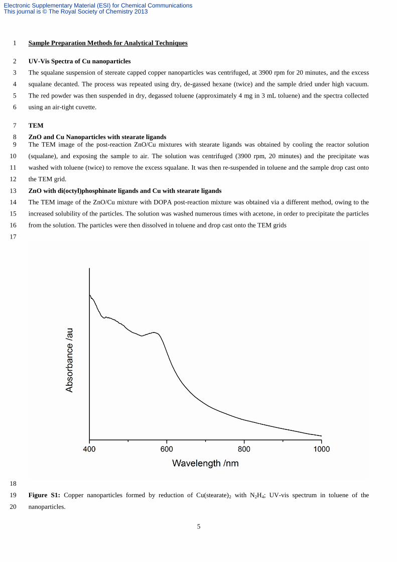
UV-Vis Spectra of Cu nanoparticles 2
The squalane suspension of stereate capped copper nanoparticles was centrifuged, at 3900 rpm for 20 minutes, and the excess 3
squalane decanted. The process was repeated using dry, de-gassed hexane (twice) and the sample dried under high vacuum. 4
The red powder was then suspended in dry, degassed toluene (approximately 4 mg in 3 mL toluene) and the spectra collected 5
using an air-tight cuvette. 6
TEM 7
ZnO and Cu Nanoparticles with stearate ligands 8 The TEM image of the post-reaction ZnO/Cu mixtures with stearate ligands was obtained by cooling the reactor solution 9
(squalane), and exposing the sample to air. The solution was centrifuged (3900 rpm, 20 minutes) and the precipitate was 10
washed with toluene (twice) to remove the excess squalane. It was then re-suspended in toluene and the sample drop cast onto 11
the TEM grid. 12
ZnO with di(octyl)phosphinate ligands and Cu with stearate ligands 13
The TEM image of the ZnO/Cu mixture with DOPA post-reaction mixture was obtained via a different method, owing to the 14
increased solubility of the particles. The solution was washed numerous times with acetone, in order to precipitate the particles 15
from the solution. The particles were then dissolved in toluene and drop cast onto the TEM grids 16
17
18
Figure S1: Copper nanoparticles formed by reduction of Cu(stearate)2 with N2H4; UV-vis spectrum in toluene of the 19
nanoparticles. 20
Electronic Supplementary Material (ESI) for Chemical CommunicationsThis journal is © The Royal Society of Chemistry 2013
6
1
2
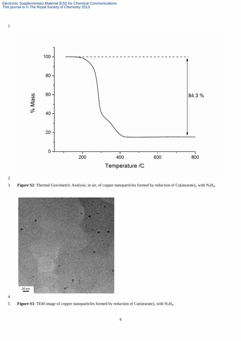
Figure S2: Thermal Gravimetric Analysis, in air, of copper nanoparticles formed by reduction of Cu(stearate)2 with N2H4. 3
4
Figure S3: TEM image of copper nanoparticles formed by reduction of Cu(stearate)2 with N2H4. 5
Electronic Supplementary Material (ESI) for Chemical CommunicationsThis journal is © The Royal Society of Chemistry 2013
7
1
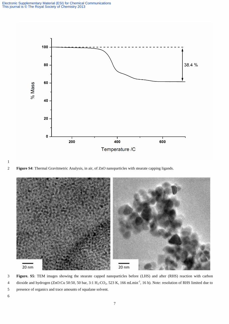
Figure S4: Thermal Gravitmetric Analysis, in air, of ZnO nanoparticles with stearate capping ligands. 2
Figure. S5: TEM images showing the stearate capped nanoparticles before (LHS) and after (RHS) reaction with carbon 3
dioxide and hydrogen (ZnO:Cu 50:50, 50 bar, 3:1 H2:CO2, 523 K, 166 mLmin-1
, 16 h). Note: resolution of RHS limited due to 4
presence of organics and trace amounts of squalane solvent. 5
6
Electronic Supplementary Material (ESI) for Chemical CommunicationsThis journal is © The Royal Society of Chemistry 2013
8
1
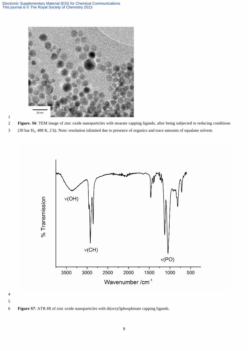
Figure. S6: TEM image of zinc oxide nanoparticles with stearate capping ligands, after being subjected to reducing conditions 2
(30 bar H2, 488 K, 2 h). Note: resolution islimited due to presence of organics and trace amounts of squalane solvent. 3
4
5
Figure S7: ATR-IR of zinc oxide nanoparticles with di(octyl)phosphinate capping ligands. 6
Electronic Supplementary Material (ESI) for Chemical CommunicationsThis journal is © The Royal Society of Chemistry 2013
9
1
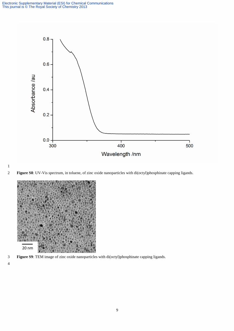
Figure S8: UV-Vis spectrum, in toluene, of zinc oxide nanoparticles with di(octyl)phosphinate capping ligands. 2
Figure S9: TEM image of zinc oxide nanoparticles with di(octyl)phosphinate capping ligands. 3
4
20 nm
Electronic Supplementary Material (ESI) for Chemical CommunicationsThis journal is © The Royal Society of Chemistry 2013
10
1
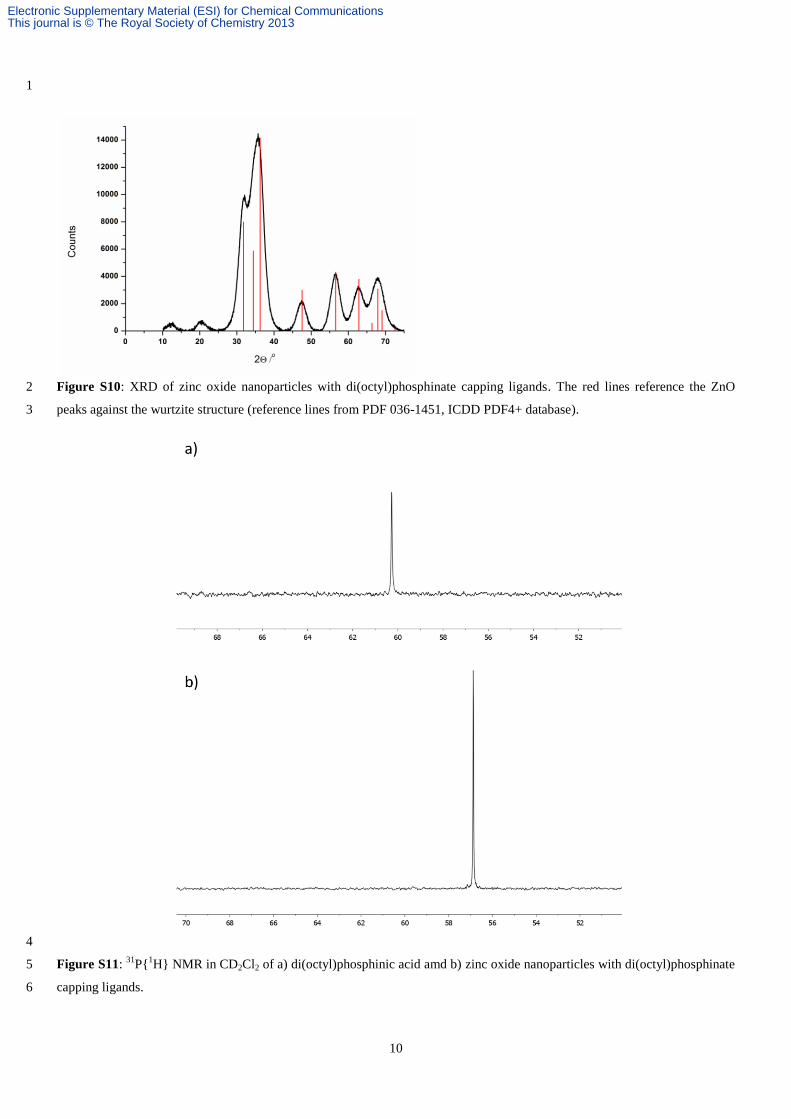
Figure S10: XRD of zinc oxide nanoparticles with di(octyl)phosphinate capping ligands. The red lines reference the ZnO 2
peaks against the wurtzite structure (reference lines from PDF 036-1451, ICDD PDF4+ database). 3
4
Figure S11: 31
P{1H} NMR in CD2Cl2 of a) di(octyl)phosphinic acid amd b) zinc oxide nanoparticles with di(octyl)phosphinate 5
capping ligands. 6
Electronic Supplementary Material (ESI) for Chemical CommunicationsThis journal is © The Royal Society of Chemistry 2013
11
1
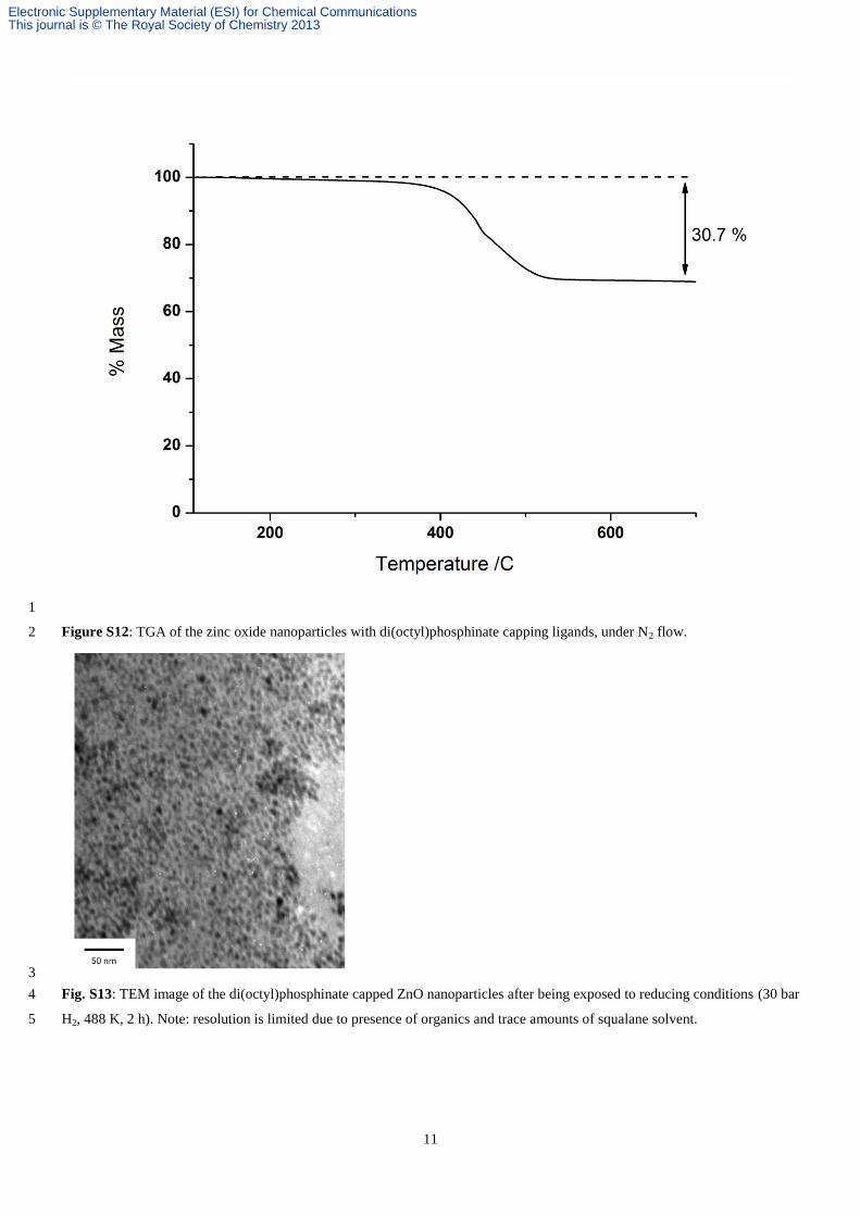
Figure S12: TGA of the zinc oxide nanoparticles with di(octyl)phosphinate capping ligands, under N2 flow. 2
3
Fig. S13: TEM image of the di(octyl)phosphinate capped ZnO nanoparticles after being exposed to reducing conditions (30 bar 4
H2, 488 K, 2 h). Note: resolution is limited due to presence of organics and trace amounts of squalane solvent. 5
Electronic Supplementary Material (ESI) for Chemical CommunicationsThis journal is © The Royal Society of Chemistry 2013
12
1
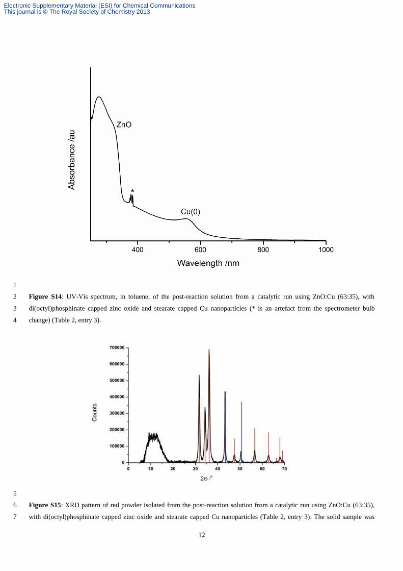
Figure S14: UV-Vis spectrum, in toluene, of the post-reaction solution from a catalytic run using ZnO:Cu (63:35), with 2
di(octyl)phosphinate capped zinc oxide and stearate capped Cu nanoparticles (* is an artefact from the spectrometer bulb 3
change) (Table 2, entry 3). 4
5
Figure S15: XRD pattern of red powder isolated from the post-reaction solution from a catalytic run using ZnO:Cu (63:35), 6
with di(octyl)phosphinate capped zinc oxide and stearate capped Cu nanoparticles (Table 2, entry 3). The solid sample was 7
Electronic Supplementary Material (ESI) for Chemical CommunicationsThis journal is © The Royal Society of Chemistry 2013
13
isolated by precipitation from squalane using excess acetone, centrifugation and drying (in vacuo). The sample isolation and 1
characterisation were maintained in an anaerobic environment to limit oxidation, where possible. The red lines reference the 2
ZnO peaks against the wurtzite structure (reference lines from PDF 036-1451, ICDD PDF4+ database) and blue lines reference 3
peaks against metallic copper.6 The peaks at low angles are assigned to the surface capping ligands (di(octyl)phosphinate and 4
stearate) and/or to residual (excess) squalane. 5
6
ZnO with DOPA Particles Theoretical Determination: 7 8
The theoretical total surface area (ST) of the samples is given as: 9
10
(1) 11
12
where SP is the surface area per particle and NP is the total number of particles, given by: 13
14
(2) 15
16
where n is the number of moles of ZnO, Vm is the molar volume of ZnO (1.4353 × 1025
Å3mol
-1) and VP is the volume per 17
particle. Assuming that the particles are perfect spheres, rearranging equations 1 and 2 gives: 18
19
(3) 20
21
where r is the radius of the particles (average of measurements by HR-TEM, UV-vis, and XRD analysis). 22
The number of moles of carboxylate per mole of ZnO, nc, for each sample was calculated from the organic content measured 23
by TGA: 24
25
(3) 26
27
where WO, Wi are the weight percent (wt%) of organic and inorganic components, respectively, and MO and Mi are the 28
molecular weight of the organic and that of ZnO respectively. 29
30
The surface area per phosphinate molecule was estimated as 24.4 Å2 using a similar method to Cooper et al.
7 based on the 31
calculated head group surface area of a phosphinate based on the literature bond lengths and bond angles of P-O and O-P-O 32
respectively. The sterate molecule was estimated to have an area of 20 Å2. 33
34
Assuming that all the phosphinates are bound to the surface and form a close packed monolayer, the theoretical surface area 35
that could be occupied by phosphinate groups, SS was then calculated as: 36
37
(4) 38
39
where Z is Avogadro’s number, and nC is the number of moles of phosphinate (calculated from the total organic content). The 40
ratio of SS to ST gives the percentage coverage. 41
42
Example calculation: 43 For a ZnO nanoparticle with an initial loading of 5 equivalents of DOPA. The nanoparticles were found to have a diameter of 44
3.5 nm by TEM, UV-Vis and XRD calculations. Thus, based on equation 3 the surface area of the particles is estimated to be 45
2.46x1024
Å2/mol (304 m
2/g). 46
47
Based on equation 4, the number of moles of DOPA is given as 48
49
50
51
These DOPA molecules will form a monolayer over a surface of: 52
53
Å2 54
55
56
Electronic Supplementary Material (ESI) for Chemical CommunicationsThis journal is © The Royal Society of Chemistry 2013
14
Which divided the by the surface area of the ZnO gives a percent coverage of: 1
2
3
4
Catalytic Activity Calculations and Plots 5
The mass of the colloidal nanoparticle catalysts were determined as the sum of the Cu and ZnO contents, as determined by 6
TGA. 7
8
1)ZnO Stearate capped particles: 9
The mass of ZnO present was determined according to: 10
m(ZnO) = m(nanoparticles) x 0.616 11
where 0.616 is determined from the 38.4% mass loss observed in the TGA, in air, due to the pyrolysis of the stearate group 12
(Fig. S4). 13
14
2)Copper stearate particles: 15
The mass of Cu present was determined according to: 16
m(Cu) = m(solution) x 0.0.125, 17
Where the multiplier 0.125 corresponds to the copper content of the residual mass of CuO (where the Cu mass fraction of CuO 18
is 0.799). The residual mass (15.7%) of CuO results from the 84.3% mass loss observed in the TGA, in air, due to the pyrolysis 19
of the stearate group (Fig. S2). 20
21
3)ZnO Phosphinate capped particles: 22
The mass of ZnO present was determined according to: 23
m(ZnO) = m(nanoparticles) x 0.703, 24
where 0.703 is determined from the 30.7% mass loss observed in the TGA (under N2) due to the pyrolysis of the phosphinate 25
group (Fig. S12). 26
27
The ratio of ZnO:Cu (w/w) was determined from these values. The mass of the ternary catalyst was determined as the sum of 28
the weight fractions of Cu and ZnO present in the sample. 29
30
The GC detector was calibrated using a range of methanol concentrations so as to enable interpolation of the methanol 31
concentrations obtained using the nanocatalysts. The concentration of methanol (Eq. 1) was determined according to the 32
method previously published by Torkelson et al.8 Eqs. 2-4 outline how the activity, FMeOH (μmol.g
-1.h
-1) was determined 33
34
Electronic Supplementary Material (ESI) for Chemical CommunicationsThis journal is © The Royal Society of Chemistry 2013
15
CMeOH (μmol.μL-1
) = the vapour concentration of methanol, GC Counts = the peak area (GC), RF = calibration constant 1
(2000000), loop size = 250 L, loop temperature = vapour temperature = 523 K, V = volumetric flow rate of the gases (166 2
μL.min-1
). 3
4
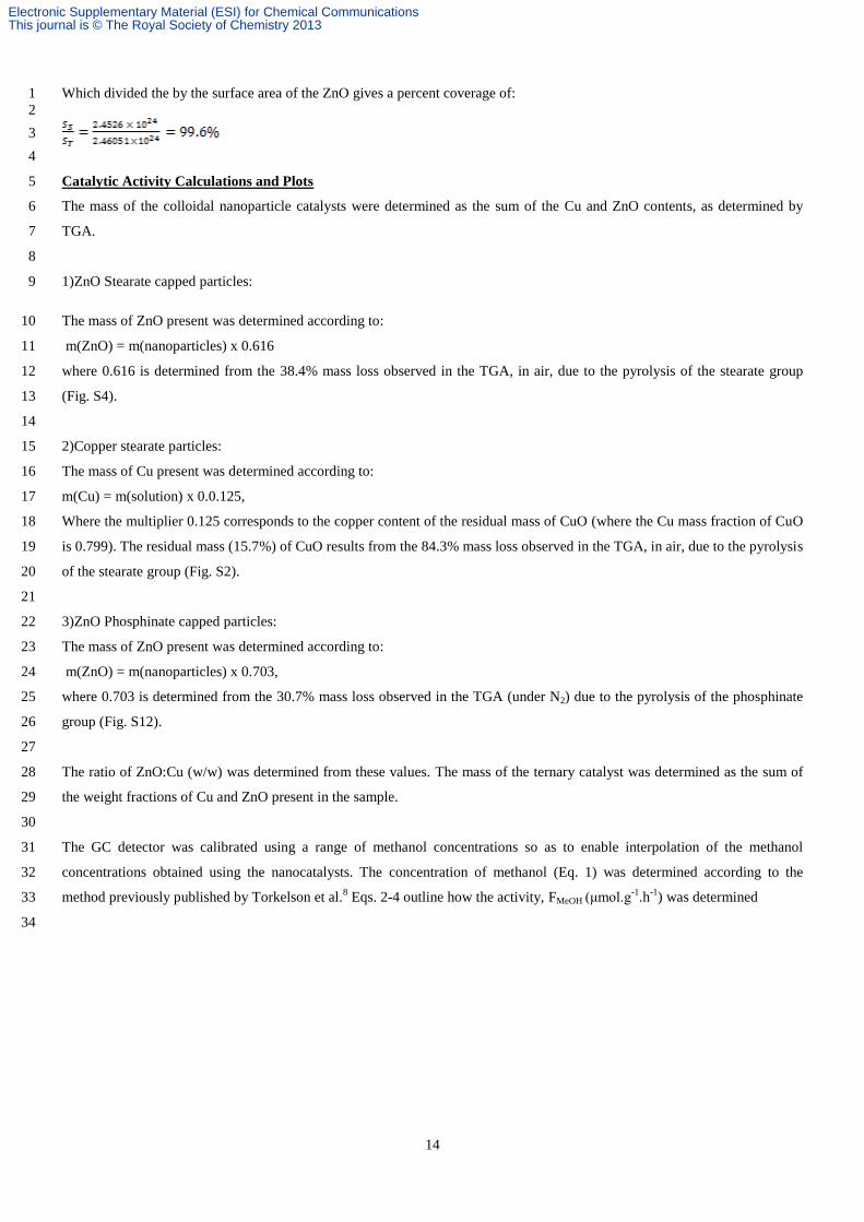
The methanol activity was monitored vs time, peak activity is reached after ~ 2 h. A representative plot is illustrated in Fig. 5
S16 6
7
Figure S16: Plot illustrating the methanol activities versus time for a representative colloidal nanocatalyst (triangles) and the 8
ternary reference (squares). The colloidal nanocatalyst refers to Table 2, entry 3: 65:35 (w/w) ZnO with di(octyl)phosphinate 9
ligands: Cu with stearate ligands). Peak activity is reached 1-2 hours and is a combination of both the colloidal catalyst re-10
structuring to form the active species and the saturation of the head-space and liquid medium with the reactants and products. 11
Cu(0) Particle Size Distribution 12
Size analysis (using ImageJ) of the TEM image (Fig. S3) gave the mean particle size to be 5.3 nm ±0.5 nm and the particles in 13
a range of 1 – 10 nm. EDX analysis of the TEM micographs collected (on gold grids) show copper pesence throughout the area, 14
indicating that copper is present on the grid as resolved particles (1 – 10 nm) and as un-resovled particles (sub 1 nm). 15
CMeOH μmol.μL−1 = GC Counts
RF .
1
loop size .
loop temp .
vapour temp . (Eq. 1)
FMeOH (μmolmin−1) = CMeOH μmol.μL−1 . V (μL. min−1) (Eq. 2)
FMeOH μmolh−1 = CMeOH μmol. min−1 . 60 (Eq. 3)
FMeOH μmolg−1h−1 =CMeOH μmol .h−1
mass of ZnO and Cu (g) (Eq. 4)
Electronic Supplementary Material (ESI) for Chemical CommunicationsThis journal is © The Royal Society of Chemistry 2013
16
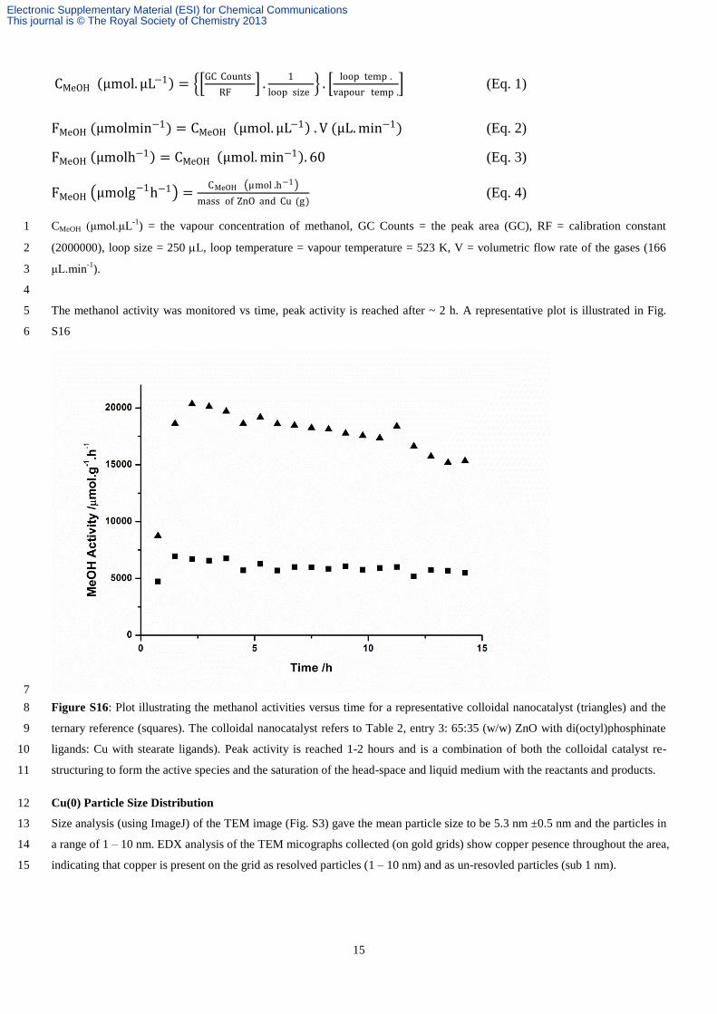
In addition, dynamic light scattering (DLS) experiments were conducted which gave a paticle size range of 7.1 – 11.3 nm. DLS 1
measurements iclude the particle as a whole, including the organic corona around the copper particles, a simple substraction of 2
the length of a stearate chain (2.8 nm) gave a size range of 1.1 – 5.7 nm. 3
Figure S17: DLS plot of Cu(0) nanoparticles in toluene in a sealed cuvette (solution filtered before through a 1 micron filter to 4
remove any dust particles) 5
6
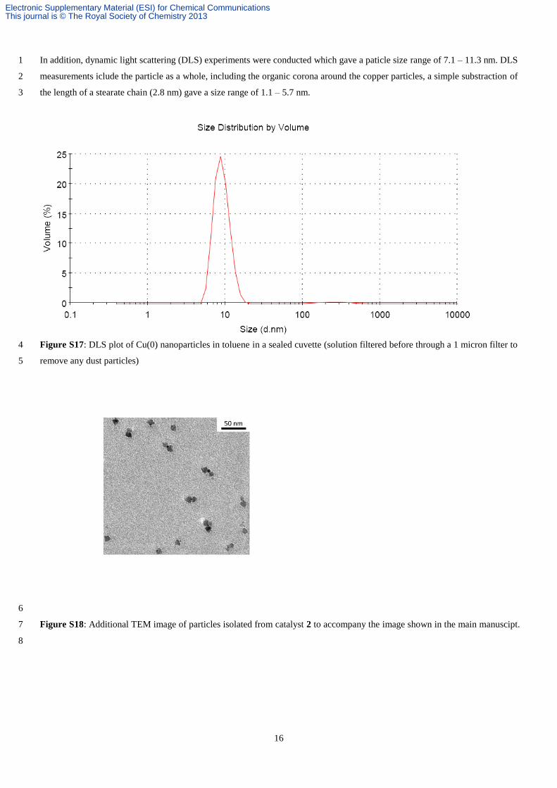
Figure S18: Additional TEM image of particles isolated from catalyst 2 to accompany the image shown in the main manuscipt. 7
8
Electronic Supplementary Material (ESI) for Chemical CommunicationsThis journal is © The Royal Society of Chemistry 2013

17
References 1
1. A. M. Godquin Giroud, J. C. Marchon, D. Guillon and A. Skoulios, Journal De Physique Lettres, 1984, 45, L681. 2
2. H. D. Gillman, Inorga. Chem., 1974, 13, 1921. 3
3. (a) H. D. Gillman and J. L. Eichelberger, Inorg. Chim. Acta, 1977, 24, 31; (b) V. Giancotti and A. Ripamonti, J. Chem. 4
Soc. A, 1969, 706. 5
4. F. Wang, R. Tang and W. E. Buhro, Nano Lett., 2008, 8, 3521. 6
5. G. P. van der Laan, A. Beenackers, B. Q. Ding and J. C. Strikwerda, Catal. Today, 1999, 48, 93. 7
6. J. D. Hanawalt, H. W. Rinn and L. K. Frevel, Industrial & Engineering Chemistry Analytical Edition, 1938, 10, 457. 8
7. R. J. Cooper, P. J. Camp, D. K. Henderson, P. A. Lovatt, D. A. Nation, S. Richards and P. A. Tasker, Dalton Trans., 9
2007, 1300. 10
8. T. Torkelson and D. S. Ballantine, Analyst, 1998, 123, 209. 11
12
Electronic Supplementary Material (ESI) for Chemical CommunicationsThis journal is © The Royal Society of Chemistry 2013