Introduction to Design of Structural Ceramics David ... · Ceramics 4 1/21/2004 designers of...
32
Introduction to Design of Structural Ceramics David Stienstra, Ph.D. Rose-Hulman Institute of Technology Copyright 1992 Revised 2003
Transcript of Introduction to Design of Structural Ceramics David ... · Ceramics 4 1/21/2004 designers of...

Introduction to Design of Structural Ceramics
David Stienstra, Ph.D. Rose-Hulman Institute of Technology
Copyright 1992 Revised 2003

Ceramics 2 1/21/2004
Goals and Overview This goal of this work is to help the designer faced with the possible use of structural ceramics. The intent is to:
• examine the advantages of ceramics in design • describe how you can approach the special problems of designing with brittle materials • introduce you to some common structural ceramics • describe how processing affects properties; • provide you with sources of information when you need to know more
At the end of the course you will probably not be able to single handedly design and build an all-ceramic gas turbine engine. You should, however, be better able to:
• understand manufacturers information • discuss problems and desires with suppliers • read the increasingly abundant information in the field
To accomplish these modest goals we will start by looking at reasons ceramics should be considered for structural applications and the special challenges of working with ceramics. In Section 1 we overview the most common structural ceramics and their manufacturing methods. The last portion will address more specific design issues including the statistical approach to design (Section 2), the problems of thermal stress (Section 3), and joining ceramics (Section 4). Why Use Ceramics for Structural Applications? Consider the turbocharger rotor (Fig 1.1) for an automobile. The design criteria include
• high temperature resistance (hot exhaust gases) • low coefficient of thermal expansion (small blade tip clearance) • low mass (low polar moment of inertia for fast spin up) • durability (survive over 100,000 miles) • low cost (need willing purchasers)
Figure 1.1 Silicon Nitride turbocharger rotors (From www.kyocera.com)
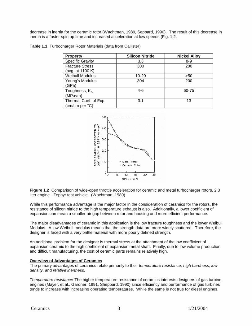
A ceramic (sintered silicon nitride) turbocharger was first used in a production vehicle in the Nissan Fairlady Z sports car in 1985 (Weidmann, et al., 1990). This was the result of work begun by Garrett Company in the 1970's. In 1990 Garrett Automotive Division of Allied Signal Automotive supplied ceramic turbochargers to Nissan Motors at a rate of more than 2000 per month. These were used in the 1990 Nissan Skyline, the world's first production car with twin ceramic turbocharger rotors. Toyota Motor Corporation also mass produces silicon nitride ceramic rotors for turbochargers (Sheppard, 1990). To see the reason for the switch to ceramics, we can look at some material properties that relate to the design criteria. Table 1.1 shows a comparison of properties for silicon nitride and a nickel alloy commonly used for turbocharger rotors. We see that the density of the ceramic is significantly lower than the metal and the strength at temperature is comparable, so we can expect that the rotating inertia of the ceramic rotor will be much smaller that for the metal. This is indeed the case, with estimates of a 50-60%
Ceramics 3 1/21/2004
decrease in inertia for the ceramic rotor (Wachtman, 1989, Seppard, 1990). The result of this decrease in inertia is a faster spin up time and increased acceleration at low speeds (Fig. 1.2. Table 1.1 Turbocharger Rotor Materials (data from Callister) Property Silicon Nitride Nickel Alloy Specific Gravity 3.3 8-9 Fracture Stress
(avg. at 1100 K) 300
200
Weibull Modulus 10-20 >50 Young's Modulus
(GPa) 304 200
Toughness, KIC (MPa√m)
4-6 60-75
Thermal Coef. of Exp. (cm/cm per °C)
3.1 13
Figure 1.2 Comparison of wide-open throttle acceleration for ceramic and metal turbocharger rotors, 2.3 liter engine - Zephyr test vehicle. (Wachtman, 1989) While this performance advantage is the major factor in the consideration of ceramics for the rotors, the resistance of silicon nitride to the high temperature exhaust is also. Additionally, a lower coefficient of expansion can mean a smaller air gap between rotor and housing and more efficient performance. The major disadvantages of ceramic in this application is the low fracture toughness and the lower Weibull Modulus. A low Weibull modulus means that the strength data are more widely scattered. Therefore, the designer is faced with a very brittle material with more poorly defined strength. An additional problem for the designer is thermal stress at the attachment of the low coefficient of expansion ceramic to the high coefficient of expansion metal shaft. Finally, due to low volume production and difficult manufacturing, the cost of ceramic parts remains relatively high. Overview of Advantages of Ceramics The primary advantages of ceramics relate primarily to their temperature resistance, high hardness, low density, and relative inertness. Temperature resistance-The higher temperature resistance of ceramics interests designers of gas turbine engines (Mayer, et al., Gardner, 1991, Sheppard, 1990) since efficiency and performance of gas turbines tends to increase with increasing operating temperatures. While the same is not true for diesel engines,
Ceramics 4 1/21/2004
designers of diesels are interested because use of ceramics may eliminate the need for a cooling system and thereby increase efficiency and lower cost (Wachtman, 1989). High hardness – Hardness is useful in impact resistance and wear resistance. The high wear resistance of ceramics is important for design of automotive components such as rocker arm pads (e.g pressureless-sintered silicon nitride, Sialon Kubel, 1989), the design of ball and roller bearings, and in the design of artificial hips. Ceramic bearings (e.g. hot-pressed silicon nitride, HPSN (Anon, 1990, Wachtman, 1989)) are attractive not only for wear resistance but because of the high temperature resistance can run longer in situations where there is a loss of lubrication. Alumina has been shown to be a very low friction substitute for metals in hip implants and is inert in the hostile environment of the human body. Other ceramics are described as bioactive, and interface seamlessly with human bone (Hulbert, et al., 1987). Ceramics have been used as cutting and shaping tools for many years. The wear and temperature resistance are ideal for this application. Low Density - The advantage of low density was developed with the example of the turbocharger rotor. This property is also certainly important in high rpm gas turbines and other rotating or reciprocating applications. Relative inertness - The corrosion resistance of ceramics is important for the biomedical implant applications mentioned earlier. It is also important for the high temperature applications where high temperature oxidation may be a significant problem in competitive metals (Sheppard, 1991). Special Design Considerations for Ceramics The special considerations of design with ceramics tend to center on their brittleness and the difficulty of manufacture. Brittleness leads to large data scatter in strength, and to a marked sensitivity to flaws. As a result, failure tends to be catastrophic rather than gradual and may occur at stresses well below what the designer expects. This is not to imply that brittle materials are weak or fragile. For example, cast iron is a very brittle material, yet a cast iron engine block is very strong and durable. Likewise, structural ceramics can be both strong and durable. Because of the large scatter in data, a statistical approach to design is needed. Important factors for the designer to know are the stresses in the part (particularly the volume of material exposed to different stress levels) and the statistical distribution of strength for the material used. These can be combined to determine the probability of failure for the part. Because of the flaw sensitivity, some knowledge of fracture mechanics is needed and care needs to be taken that stress concentrations are minimized in the part design. Likewise, the manufacturing method should be such as to make the part as homogenous internally and as smooth externally as possible. Difficulty in manufacturing can limit the size and shape of the product and can exacerbate the scatter in strength data. As you might expect, conventional casting, forging, cold forming, and welding are not applicable to ceramics. Manufacturing methods are more similar to those used in powder metals, although extrusion and injection molding are also used. In addition, joining of ceramics to metals presents problems because of the difference in thermal expansion between the two materials. The lack of ductility and the mismatch in thermal expansion with metals make thermal stress an important consideration.
Section 1 - Comparing Properties of Ceramics with Metals and Polymers
General Properties of Ceramics Ceramics tend to be hard, stiff, brittle, electrical insulators with low coefficients of expansion. These properties result from strong ionic and covalent atomic bonding. The following sections describe the properties of the different types of ceramics and how they compare with metals and polymers.

Ceramics 5 1/21/2004
Melting Temperature Melting temperature is very closely related to strength of atomic bonding and thus the melting temperatures of ionic and covalently bonded ceramics tends to be higher than for metals and polymers as shown in Table 1.2 below. Exceptions include the weakly bonded NaCl (table salt) and strongly bonded metals like tungsten. Table 1.2 Melting Temperatures of Selected Metals, Polymers, and Ceramics
Material Melting Temperature oC
NaCl 801 Aluminum 660 Iron, Fe 1535 Ni based superalloy 1260-1335 W 3300 Al2O3 2045 SiC 2500* Si3N4 1900* ZrO2 2700 Thermal Expansion Thermal expansion is also controlled by strength of atomic bonds since the amplitude of the atom’s vibrations will be smaller at a given temperature if strength is high. Expansion is usually measured by the coefficient of thermal expansion, a factor that represents how much the material will increase in length for a given temperature increase. Linear coefficients of thermal expansion are compared below in Table 1.3 (Because crystallographic orientation affects expansion, the data shown are for polycrystalline materials). One can see a mismatch between metals, polymers, and ceramics. This can be significant when a joint between a metal and ceramic must cycle through a temperature range. Then the difference in expansion can lead to significant thermal stresses and possible thermal fatigue. The magnitude of the thermal coefficient of expansion is also important in cases of thermal shock. Gas turbine components may see dramatic temperature changes on startup and shut down. In that case materials with very low coefficients of expansion (like Pyrex) show small thermal stresses. Note that a ceramic with a very low coefficient can be good when used alone but may not be when mated with a metal. Table 1.3 Thermal Expansion Coefficients for Selected Metals, Polymers and Ceramics (polycrystalline).
Material
Linear Thermal Exp. Coef. (cm/cm °C x 106)
Nylon 6,6 144 Polycarbonate 122 Al alloys 21-24 Fe alloys 12 Ni based superalloy 12-17 W 4.5 Al2O3 7-8 SiC 4.1-4.6 Si3N4 2.7-3.1 ZrO2 9-10
0 500 1000 1500 2000 2500 3000 3500
Al
Fe
Ni
W
Al2O3
SiC
Si3N4
ZrO2
Melting Temp, C
0 20 40 60 80 100 120 140
NylonPC
Al Fe Ni
WAl2O3
SiC
Si3N4ZrO2
Thermal Coef of Exp

Ceramics 6 1/21/2004
Modulus of Elasticity The modulus of elasticity (Young's Modulus) is the ratio of stress to strain in the elastic region and thus represents the elastic stiffness of the material. Since the source of elastic strain is bond stretching, this too is a function of atomic bond strength. As temperature increases and the material expands, average atom spacing increases and the modulus of elasticity tend to decrease slightly. Modulus also varies with crystallographic direction, but is considered to have a single value for polycrystalline materials. A comparison of moduli at room temperature is shown below in Table 1.4. Table 1.4 Elastic Modulus for Selected Metals, Polymers, and Ceramics
Material
Elastic Modulus (psi x 106)
Nylon 6,6 1.6-3.8 Polycarbonate 1.9-3 Al alloys 10 Fe alloys 30 Ni based superalloy 30.4 W 58 Al2O3 40-55 SiC 30-70 Si3N4 44 ZrO2 20 Electrical Conductivity Since charge is generally carried by electrons, metals, with their many "free electrons" tend to be excellent conductors. Ceramics, due to their ionic or covalent bonding, have more tightly held electrons and tend to be electrical insulators. There is a wide range of behavior among ceramics however, and some transition metal oxides can approach the conductivity of metals. The structural ceramics are poor conductors and are either semiconductors, like SiC, or insulators like alumina and silicon nitride. Typical resistivities for the materials are shown below in Table 1.5. Table 1.5 Electrical Resistivities for Selected Metals, Polymers, and Ceramics
Material
Resistivity (ohm-m)
Nylon 6,6 1012 Polycarbonate 1014 Ni based superalloy 10-7 Al alloys 10-8 Fe metal 10-7 W 10-8 ZrO2 1010 SiC 109 Si3N4 1014 Al2O3 1014
0 10 20 30 40 50 60 70
Nylon
PC
Al
Fe
Ni
W
Al2O3
SiC
Si3N4
ZrO2
Elastic Modulus, 1000 ksi
1.E-08 1.E-05 1.E-02 1.E+01 1.E+04 1.E+07 1.E+10 1.E+13 1.E+16
Nylon
PC
Al
Fe
Ni
W
Al2O3
SiC
Si3N4
ZrO2
Resistivity ohm - m

Ceramics 7 1/21/2004
Thermal Conductivity That ceramics can have good thermal conductivity is surprising to many people. In fact, diamond is the best thermal conductor known (at room temperature) and materials like SiC and BeO conduct heat better than iron (Figure 1.3, Table 1.6). Normally, we think that electrical and thermal conductivity go hand in hand, and in metals they do. In the case of ceramics, however, other mechanisms for conduction of heat are possible and ceramics can vary from relatively good thermal conductors to excellent thermal insulators. Phonons or quantized vibrations of the crystal lattice are the mechanism for efficient conduction of heat in ceramics. Figure 1.3 Thermal Conductivity of Selected Metals and Ceramics (Richerson,1992) Ceramics can have an advantage when electrical resistivity and thermal conductivity are needed at the same time. One such application is in substrates for electronic circuitry where heat dissipation is needed. Thermal conductivity also depends upon temperature and this dependence is much stronger for some materials than for others (as seen in fig 1.3). In addition, effective thermal conductivity also depends upon processing because of the insulating effect of porosity. Table 1.6 Room Temp thermal conductivities for Selected Metals, Polymers, and Ceramics
Material
Thermal Conductivity W/m-K
Nylon 6,6 0.24 Polycarbonate 0.20 Ni based superalloy 10-20 Al alloys 130-220 Fe alloys 52 W 155 ZrO2 2-3 SiC 70-80 Si3N4 10-30 Al2O3 16-40 Graphite 100-190 Diamond 1500-4700 Ductility Ductility in structural ceramics is very small at most temperatures, and thus they can be said to be brittle materials for the purposes of design. This brittleness leads to a number of problems including scatter in strength data and extreme flaw sensitivity. Because the ceramics can't plastically deform to redistribute stresses, stress concentrations and thermal gradients can cause much larger problems than they would with metals. A good measure of this is the fracture toughness as shown in Table 1.7. Table 1.7 Fracture Toughness, KIC for Selected Metals, Polymers, and Ceramics
Material
Fracture Toughness MPa√m
Nylon 6,6 2.5-3 Polycarbonate 2.2 Ni based superalloy 60-75 Al alloys 20-60 Fe metal 20-100 ZrO2 7-12 SiC 5-6

Ceramics 8 1/21/2004
Si3N4 4-6 Al2O3 4-6 Strength Strength of ceramics is very dependent upon the flaw distribution in the materials. These "flaws" can be of a microscopic nature and may not be flaws from a normal perspective. For example, the strength of glass fibers is the highest immediately after manufacture, and simply handling them with clean hands can cause sufficient surface damage to reduce strength by 30%. Because small flaws can have a very large effect, the strength data of ceramics tends to be widely scattered. The most practical way of dealing with widely scattered data is the use of statistics. In the case of ceramic strength data, the standard statistical model is the Weibull distribution. A Weibull parameter (Weibull slope, Shape parameter, Weibull Modulus) is often stated when describing the strength of a ceramic. The meaning and use of this parameter is discussed in Section 2. Another result of flaw sensitivity is that ceramics are much stronger in compression than tension (it is hard to open a crack in compression). Testing of ceramics is often done in bending and the failure stress in bending is often called the Modulus of Rupture, MOR. Table 1.8 shows the typical ranges of strengths for a variety of ceramics. Tensile strengths are typically lower than MOR as explained in Section 2. Table 1.8 Strength of ceramics (Richerson, 1992)

Ceramics 9 1/21/2004
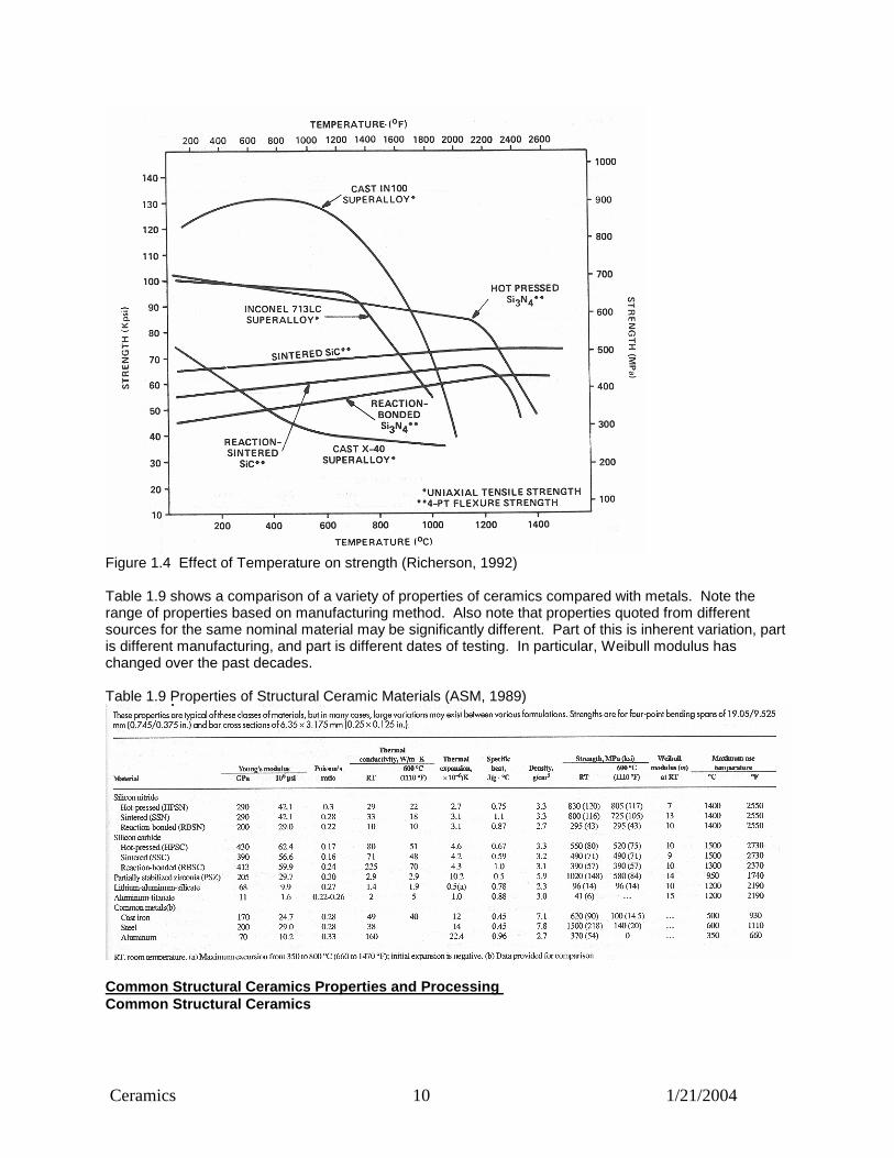
Because ceramics are used at high temperature, strength at temperature is also a concern. Figure 1.4 shows the comparison of ceramics and competitor metals. Note that the oxides, alumina and zirconia are not shown. They tend to be weaker at temperature and not competitive with silicon nitride and silicon carbide for high temperature, high strength applications.
Ceramics 10 1/21/2004
Figure 1.4 Effect of Temperature on strength (Richerson, 1992) Table 1.9 shows a comparison of a variety of properties of ceramics compared with metals. Note the range of properties based on manufacturing method. Also note that properties quoted from different sources for the same nominal material may be significantly different. Part of this is inherent variation, part is different manufacturing, and part is different dates of testing. In particular, Weibull modulus has changed over the past decades. Table 1.9 Properties of Structural Ceramic Materials (ASM, 1989)
Common Structural Ceramics Properties and Processing Common Structural Ceramics

Ceramics 11 1/21/2004
The families of ceramics most commonly used for structural applications are silicon carbide (SiC), silicon nitride (Si3N4), zirconia (ZrO2), and alumina (Al2O3). Many others could be included, but these four are representative. Aluminum Oxide This is the most commonly used advanced ceramic, primarily because of its lower cost (relative to other ceramics), excellent environmental resistance, and excellent room temperature properties. Low conductivity leads to applications in electronic products. It is used in spark plugs, http://www.grantadesign.com/resources/process/casestudies/sparkplug.htm ,armor plate http://www.morganadvancedceramics.com/press/bodyarmo.htm , and hip implants http://www.wmt.com/Downloads/AluminavsZirconiaWhitepaper.pdf Because the strength of AL2O3 falls off at high temperature, it is not as attractive as silicon nitride or silicon carbide for gas turbine applications. Zirconia The biggest selling features for Zirconia is the potential for high toughness and the closer match of thermal expansion with steel. It also is able to hold an edge well. Zirconia may be seen in consumer products such as ceramic kitchen knives http://www.kyoceratycom.com/FineCeramics/Products/kitchen.htm and it is used as die and cutting materials in manufacturing http://www.cartech.com/epg_cac/ , http://www.dynacer.com/cutting_slitting.htm. Like AL2O3, it is less likely to be used at very high temperatures due to declines in strength. Zirconia exists in toughened forms not because it is more ductile, but because of a microstructural transformation similar the austenite-martensite transformation in steel. We saw that when steel transformed to Martensite there was a significant volume increase due to the less closely packed microstructure. Zirconia can also exist in different crystal structures and transformation can occur in response to stress. In transformation toughened Zirconia, there are scattered regions of a microstructure that changes phase (with attendant increase in volume) in response to stress. Thus, when a crack tries to propagate through the ceramic, the stress field ahead of the crack triggers a phase change in part of the microstructure. This local attempt of some grains to increase in volume results in a local compressive field ahead of the crack, stopping the crack propagation. As an additional bonus, Alumina and Zirconia can be combined to make a transformation toughened alumina. Silicon Carbide Silicon carbide is notable among structural ceramics for thermal conductivity. It also has the high corrosion resistance and good strength at high temperatures. Applications include mechanical seals, http://www.carbo.com/applications/seals.html , heat exchangers in the chemical processing industry http://www.chemicals-technology.com/contractors/heattransfer/st_gobain/ and impellers and valves http://www.omegaslate.com/advancedceramics.htm Silicon Nitride Silicon Nitride is one of the first choices for Gas Turbine components (Richerson), foremost because of its thermal shock resistance, but also because of its combination of high temperature strength, low density, and good corrosion resistance http://www.kyocera.com/kicc/automotive/products/gasprods.htm . Because of those attributes, it is also the material used for automotive turbocharger rotors. The closest competitor for these applications is Silicon Carbide. A good overview of Silicon Nitride is found at http://www.azom.com/details.asp?ArticleID=53.

Ceramics 12 1/21/2004
Importance of manufacturing methods on properties. Table 1.10 from the Ceradyne web site shows the marked differences in properties between sintered silicon nitride SSN and reaction bonded silicon nitride RBSN. RBSN (Ceralloy 147-1) has lower strength, lower stiffness, lower toughness, lower thermal conductivity, and a poorer Weibull modulus than the sintered grades. The reason for this is primarily a result of the lower density. You can see that this RBSN has only 75% of theoretical density and so has significant porosity. The pores act as flaws that decrease strength and toughness, and act to make the material a better insulator. You may well ask why you would use RBSN; and it is due the ease of making parts to near net shape. The process of sintering generally involves a shrinkage of the part as pores are lost during diffusion of the particles. In Reaction Bonding, Nitrogen is infiltrated through a green body of silicon particles. While this doesn’t produce a fully dense part, there is little change of size and shape. Table 1.10 Ceradyne's Ceralloy Family of Silicon Nitrides Silicon Nitride Properties
Property Ceralloy 147-31E Ceralloy 147-31N Ceralloy 147-1E Ceralloy 147-1 Process Sinter Sinter Hot Press Reaction Bonded Density (g/cc) 3.25 3.21 3.1 2.4 Density (% Theoretical) >99.3 >99.5 >98.5 75
Flexural Strength (MPa) @ RT 700 800 700 240
Weibull Modulus 10-15 15-30 18 10 Elastic Modulus (GPa) 310 310 310 175
Poisson's Ratio 0.27 0.27 0.27 0.22 Hardness HV(0.3) Kg/mm2 1800 1800 1800 800
Fracture Tough. (MPa m1/2) 6.0 5.8 5.0 2.5
Abrasive Wear Resistance 1130 1110 1120 360
Thermal Exp Coeff. 10-6/C; 3.1 3.1 3.2 3.2
Thermal Cond (W/mK) @ 25 C 26 26 42 14
Thermal Shock Parameter (C)** 530 610 540 330
Elecrical Resistivity (ohm-cm) 10^14 10^14 10^14 10^14
Applications Cutting Tools, Wear Components
Automotive Components, Bearings, Wear Components
Semiconductor Components, Wear Components
Electrical Insulators, Sputtering Targets, Semiconductor Components
Key Features Impact Strength, Net Shape Fabrication
Strength, Hertzian Contact Strength, Structural Reliability, Net Shape Fabrication
High Purity, Excellent Mechanical Properties
High Purity, Net Shape Fabrication

Ceramics 13 1/21/2004
Summary of Materials Authors McLean and Hartsock summarize the key features of this suite of materials as 1) Hot-pressed silicon nitride (HPSN) has the strongest specific strength (strength/density) at 600oC
of any material. It has excellent thermal shock resistance. 2) Sintered silicon nitride (SSN) has high strength and can be formed into complex shapes. 3) Reaction-bonded silicon nitride (RSBN) can be formed into complex shapes with no firing
shrinkage. 4) Hot-pressed silicon carbide (HPSC) is the strongest of the silicon carbide family and maintains
strength to very high temperatures (1500oC). 5) Sintered silicon carbide (SSC) has high temperature capability and can be formed into complex
shapes 6) Reaction-bonded silicon carbide (RSBC) can be formed into complex shapes and has high
thermal conductivity. 7) Partially stabilized zirconia (PSZ) is a good insulator and has high strength and toughness. It has
thermal expansion close to iron, facilitating shrink fit attachments. These rules of thumb are only useful only if we know the differences between the designations "sintered" and "hot-pressed" or between "sintered and "reaction-bonded." Consequently, more discussion of the primary manufacturing methods is in order. Manufacturing of Ceramics The majority of ceramics are made from powders that are formed and compacted into a "green" body, then heated or "fired" to sinter the particles together and drive off binding materials. In simplest terms this can be viewed as making and baking sand castles. Sometimes, the shaping and sintering steps are combined into a single process. The size and purity of the powders, the compaction in the green state and the final fired density are all important factors in the properties developed. What follows is a brief outline of the manufacturing techniques. Shaping Methods Shaping methods include die pressing, isostatic pressing, extrusion, injection molding and slip casting, as outlined in Figure 1.5.
Figure 1.5 Forming Processes for Ceramics (Weidmann, et al., 1990)
Uniaxial pressing - Uniaxial pressing (Die pressing) is the most common process for small ceramic components. High production rates (hundreds of pieces per minute) can be achieved. Sizes range from about 0.1 mm to 100 mm with dimensional tolerance on the final product of about 1%. Millions of capacitor dielectrics are made by this method. The main limitations are that only simple shapes (plates, disks, and rings) can be made and there is difficulty maintaining uniform density due to friction in the mold (Fig. 1.6). Differential density can lead to differential shrinkage on firing or to variation in properties.
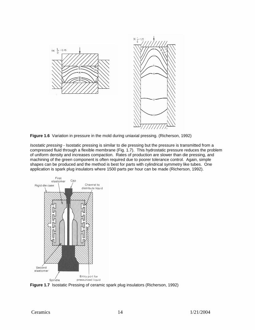
Ceramics 14 1/21/2004
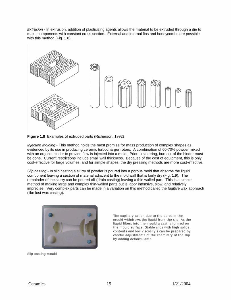
Figure 1.6 Variation in pressure in the mold during uniaxial pressing. (Richerson, 1992) Isostatic pressing - Isostatic pressing is similar to die pressing but the pressure is transmitted from a compressed fluid through a flexible membrane (Fig. 1.7). This hydrostatic pressure reduces the problem of uniform density and increases compaction. Rates of production are slower than die pressing, and machining of the green component is often required due to poorer tolerance control. Again, simple shapes can be produced and the method is best for parts with cylindrical symmetry like tubes. One application is spark plug insulators where 1500 parts per hour can be made (Richerson, 1992).
Figure 1.7 Isostatic Pressing of ceramic spark plug insulators (Richerson, 1992)
Ceramics 15 1/21/2004
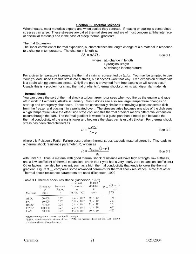
Extrusion - In extrusion, addition of plasticizing agents allows the material to be extruded through a die to make components with constant cross section. External and internal fins and honeycombs are possible with this method (Fig. 1.8).
Figure 1.8 Examples of extruded parts (Richerson, 1992) Injection Molding - This method holds the most promise for mass production of complex shapes as evidenced by its use in producing ceramic turbocharger rotors. A combination of 60-70% powder mixed with an organic binder to provide flow is injected into a mold. Prior to sintering, burnout of the binder must be done. Current restrictions include small wall thickness. Because of the cost of equipment, this is only cost-effective for large volumes, and for simple shapes, the dry pressing methods are more cost-effective. Slip casting - In slip casting a slurry of powder is poured into a porous mold that absorbs the liquid component leaving a section of material adjacent to the mold wall that is fairly dry (Fig. 1.9). The remainder of the slurry can be poured off (drain casting) leaving a thin walled part. This is a simple method of making large and complex thin-walled parts but is labor intensive, slow, and relatively imprecise. Very complex parts can be made in a variation on this method called the fugitive wax approach (like lost wax casting).
The capillary action due to the pores in the mould withdraws the liquid from the slip. As the liquid filters into the mould a cast is formed on the mould surface. Stable slips with high solids contents and low viscosity's can be prepared by careful adjustments of the chemistry of the slip by adding deflocculants.
Slip casting mould

Ceramics 16 1/21/2004
Assembled Slip cast mould ready for pouring Sintered slip cast component illustrating the
shrinkage from the original mould dimensions
http://www.dynacer.com/slip_casting.htm Figure 1.9 Slip casting example from www.dynacer.com Sintering After the formed parts are dried, they are sintered to densify the ceramic. Temperatures are a relatively high fraction of the material's melting temperature so that sufficient diffusion occurs to get the particles to fuse. The pores between the particles of the green body shrink and disappear as the solids diffuse together and flow viscously (Fig. 1.10). Because the pores are collapsing, significant shrinkage occurs. Fine powders have larger surface area and sinter more quickly and/or at lower temperatures than coarser particles.
Figure 1.10 Diffusion of the particles at sintering temperatures (Richerson, 1992) Pressureless Sintering -Sintering can be done at atmospheric pressure, called pressureless sintering. Usually this requires some sintering aids. Problems can come from nonuniform packing (such as can occur in uniaxial pressing). Particle size distribution is also important. Single size particles do not pack as efficiently as particles with a range of sizes and therefore will tend to have larger porosity or more shrinkage. particle shape can play a role since rodlike or elongated particles tend to "bridge" during forming more than spherical particles, thus leaving larger and more irregular pores. Other sintering problems include warpage, excessive grain growth, phase transformations, and cracking. The latter can occur when binders are removed too quickly. Liquid-phase Sintering- In liquid-phase sintering additives to the powder act to lower the melting temperature so that 2-20% liquid phase is present during the sintering process. An example is the

Ceramics 17 1/21/2004
addition of yttria to silicon nitride. The liquid forms a surface film which provides a surface tension that aids densification and pore elimination. Knowledge of the appropriate phase diagrams is needed to anticipate problems in processing or in use. Reaction Sintering - In this process, densification is helped by a chemical reaction between the solid powder and a liquid or gas phase. Reaction-bonded (or reaction-sintered) silicon nitride, RBSN, is made by firing a compacted elemental silicon powder in a nitrogen atmosphere. The nitrogen permeates the porous Si and reacts to form Si3N4. Dimensional changes can be as low as 0.1%. Densities will be well below theoretical and strengths are consistently lower than with other sintering methods. The porosity also leads to more problems with high temperature oxidation. RBSN has the advantage of good creep resistance because there are no glassy grain boundary regions. The thermal shock resistance is also good due to low elastic modulus (high porosity) low coefficient of expansion, and relatively high thermal conductivity. Possible applications include welding nozzle tips, static structural components for gas turbines, and aluminum metal processing (Richerson, 1992). Reaction bonded silicon carbide, RBSC, is made by infiltrating liquid silicon into a compact of carbon and silicon carbide. The Si reacts with the carbon to form SiC which then bonds with the original SiC particles. Pores are filled with liquid Si. Consequently, high temperature strength falls off at silicon's melting temperature. Dimensional changes with RBSC can be less than 1%. One interesting variation is to use carbon fibers rather than carbon particles. Combined Processing Hot Pressing - In hot pressing, temperature and pressure are combined to form and sinter the powder simultaneously. The parts are pressed mechanically between dies and the assembly is heated. The combination allows for lower temperatures and better control of the microstructure of the end product. Larger cross sections can be made and smaller amounts of sintering aids are required. The equipment and tooling required are more expensive than traditional processes, and the process is restricted to fairly simple shapes. Hot Isostatic Pressing - In hot isostatic pressing an inert gas is used to transmit pressure instead of dies. Therefore tool costs are lower. In addition, shapes can be complex and multiple parts can be processed in the same pressure vessel. Coatings Sometimes the advantages of ceramics (such as temperature and wear resistance) can be realized with a thin coating. In these cases, a different manufacturing method is used. The two primary means for applying coatings are vapor deposition and molten spray deposition. Vapor deposition - Chemical vapor deposition (CVD) and sputtering are the most common. CVD produces a very fine grained and hard coating but it is a slow process. Sputtering is also slow and only thin coats can be applied. Molten spray deposition (flame spray or plasma spray) - Much thicker coatings can be made more quickly with this method. Coatings can be for wear resistance such as CR2O3 in shafts or can be to encourage bone ingrowth such as HA (hydroxyapatite) on human implants. Summary of Section 1
1. Ceramics tend to be hard, strong, brittle electrical insulators that melt at high temperatures 2. Fabrication of ceramics often involves the shaping and sintering of powders 3. Material properties of ceramics are dependent upon manufacturing, primarily due to internal flaws

Ceramics 18 1/21/2004
Section 2- Statistical Approach to Design In much of the design work you have done to date you have done deterministic rather than statistical design. You may have calculated a maximum stress of 25 ksi in a beam and were satisfied because that value was below the published minimum strength of 36 ksi for A36 steel. This is deterministic design because the strength of the material is reasonably known to be single valued. We can find a definable minimum with metals since the statistical distribution of strength is relatively narrow and there are no significant effects do to volume (thus strength of a large beam is predicted by a small test bar). For ceramics the scatter in data is much larger because they are brittle. Brittle materials can be viewed as weakest link materials in which failure occurs when the local stress exceeds the local strength. Since brittle materials can’t relieve local stress concentrations by plastic deformation, the local internal stress concentrations (pores, cracks, and inclusions) act as weak links in the chain to initiate failure and determine the failure probabilities. To quantify the distribution of strengths for weakest link materials like ceramics, engineers us Weibull statistics. The Weibull distribution is preferred to the Normal distribution because Weibull derives from weakest link theory and because Weibull is a better fit to the data. Comparing Weibull and Normal Normal -To help understand Weibull statistics, review of Normal statistics is helpful. The Normal distribution is characterized by a bell shaped curve (Fig. 2.1). The equation of the curve is
2
2
2)(
21 s
x
es
yµ
π
−−
= eqn 2.1
Where: y=frequency x=data value µ=mean s=standard deviation
Figure 2.1 Probability Density Function, PDF, for a normal distribution (bell curve) If the normal distribution represents material strength we know that half the population would fail if the stress I at the mean value. If we want to know the stress level at which 20% of the population would have failed, the PDF is not as useful as the Cumulative Distribution Function (CDF):
dxes
xFx
sx
∫∞−
−−
= 2
2
2)(
21)(
µ
π eqn 2.2
Where: F(x)=cumulative probability To find the stress at which 20% fail we set F(x) to 20% and solve for x.

Ceramics 19 1/21/2004
Weibull – The easiest way to describe a Weibull distribution is from its CDF. For a unit volume of material, the distribution of strengths is
m
eF
−
−= 01)( σσ
σ eqn 2.1 Where: σ=stress m=Weibull modulus σ0=scale parameter This is the simplest form of the two parameter Weibull distribution. It igores volume effects, multidimensional stress, and threshold strength. It is, however, much easier to grasp intuitively than the more complex forms. Interpretation of the Weibull parameters Weibull Modulus – The Weibull modulus or shape parameter or Weibull slope determines the shape of the PDF (Fig 2.4). As the Weibull modulus increases, the relative scatter of the data decreases. Ceramics such as brick tend to have Weibull modulus below ten while structural ceramics are much higher, usually in the 10’s to 20’s. If metal strength is characterized with a Weibull distribution, values are generally greater than 50. Scale parameter – The scale parameter is usually not reported and is not important for our purposes. For the curious, it represents the 63rd percentile of the distribution. Implications of Weibull distribution If the two parameter distribution is used, zero is the lowest possible failure stress(this shouldn’t bother those who have been using the normal distribution, since the lowest possible failure stress for that is minus infinity). Consequently, we can’t design to a zero failure rate, but to some finite probability of failure. To do that we make use of the CDF. If we take the log the CDF and manipulate we get
( )[ ]0
10
or1ln
σσσσ
mF
mF
CF
=−−=
eqn 2.3
Where σf is the value of stress at the Fth percentile and Cm is the value of the multiplier for a particular Weibull modulus, m. Values for the constant C are shown in Table 2.1 and a couple of examples will improve intuitive understanding. Suppose we want to design for a 99% survival rate or F=0.01. Since C is a multiplier of a constant value σ0, the C values for different percentiles can be compared to look at relative scatter. If the Weibull modulus is 4, the first percentile of the data (C=0.317) is about a third of the value for the median (C=0.912). Thus if the median were 100 ksi the design value would be about (0.317/0.918)*100 or 35ksi. For a Weibull modulus of 10 the C value for 1% failure is about 65% of that for the median for a design value of 65 ksi if the median stays at 100 ksi. For m=20, the 1% design value is about 80% of the median value of the distribution or about 81 ksi. So we can see that one key to raising minimum design values is to raise the Weibull modulus and decrease the data scatter. Its not that simple The analysis above is somewhat simplified. For example, since fracture of ceramics is a weakest link process, we expect a longer chain (larger volume) to be weaker than a shorter chain (small volume). This turns out to be true and it has implications for design and for testing. Additionally, multiaxial stresses need to be considered. Implications for Testing Because of the brittleness of ceramics, they have traditionally been tested in bending (3-point or 4-point) rather than tension. The maximum stress to fail in bending is calculated from the failure load and geometry through the beam equations. This calculated failure stress is given the somewhat unfortunate

Ceramics 20 1/21/2004
name Modulus of Rupture, MOR. Also unfortunately, this MOR depends upon the type of specimen used. Three point bend specimens have maximum stress at a single point, while four point bend specimens have a maximum stress over a line. Thus the 4-point specimens sample a larger volume of material with high stress and are more likely to find a weak link at a lower stress (figure 2.2. Therefore, test results from 4-point testing tends to find lower MOR’s than 3-point testing. The most volume tested at the same stress occurs in the tensile bar, and despite the difficulties in specimen preparation and testing, that is the likely method for the future (Richerson).
Figure 2.2 Test specimens for measuring ceramic strength Implications for Design With metals you can measure strength with a small test specimen and predict strength of a large part, but with brittle materials the volume of both must be considered. Also multiaxial stresses may be important. Statistical software - In fact what you would like to do is consider each small part of the volume of the part at design load and calculate the local probability of failure due to the local stress and the probability of finding a weak enough link at that spot. Then you could sum up all the local probabilities of survival to get the overall part’s probability of survival. This sounds like the sort of thing you could do with finite element analysis and probability software, and indeed, NASA developed such a program currently called CARES/LIFE http://www.grc.nasa.gov/WWW/LPB/cares/life/ which is available for users in the USA. A companion program, CARES/CREEP looks at long term survival. Proof Testing - Those of you who don’t trust the analysis folks may believe they have a way to get rid of all the weak links by simply proof testing (loading all the parts to above the design load and selling the ones that don’t break). This indeed is a good , though expensive, way of assuring that only good parts make it to market. The only problem is that sometimes the surviving parts have received damage that can lead to failures later on. Summary
1. Statistical Design means working with a finite probability of failure 2. A high Weibull modulus is good because scatter in strength data is lower 3. The volume of the test pieces and the designed parts must be considered 4. Proof testing is one way to cut off the tail of the statistical distribution 5. Statistical software exists to help analysts deal with the scatter and volume issues
Ceramics 21 1/21/2004
Section 3 - Thermal Stresses When heated, most materials expand and when cooled they contract. If heating or cooling is constrained, stresses can arise. These stresses are called thermal stresses and are of most concern at thhe interface of dissimilar materials and in the case of steep thermal gradients. Thermal Expansion The linear coefficient of thermal expansion, a, characterizes the length change of a a material in response to a change in temperature. The change in length is: 0TLL ∆=∆ α Eqn 3.1
where ∆L=change in length L0 =original length ∆T=change in temperature
For a given temperature increase, the thermal strain is represented by ∆L/L0. You may be tempted to use Young’s Modulus to turn this strain into a stress, but it doesn’t work that way. Free expansion of materials is a strain with no attendant stress. Only if the part is prevented from free expansion will stress occur. Usually this is a problem for sharp thermal gradients (thermal shock) or joints with dissimilar materials. Thermal shock You can guess the sort of thermal shock a turbocharger rotor sees when you fire up the engine and race off to work in Fairbanks, Alaska in January. Gas turbines see also see large temperature changes on start-up and emergency shut down. These are conceptually similar to removing a glass casserole dish from the freezer and placing it in a preheated oven. The stresses arise because one side of the dish sees a high temperature while the other side stays cool and this thermal gradient means differential expansion occurs through the part. The thermal gradient is worse for a glass pan than a metal pan because the thermal conductivity of the glass is lower and because the glass pan is usually thicker. For thermal shock, stress has been characterized as
ν
ασ−∆=
1TE
Eqn 3.2
where ν is Poisson’s Ratio. Failure occurs when thermal stress exceeds material strength. This leads to a thermal shock resistance parameter, R, written as
( )E
R fracture
ανσ −= 1
Eqn 3.3
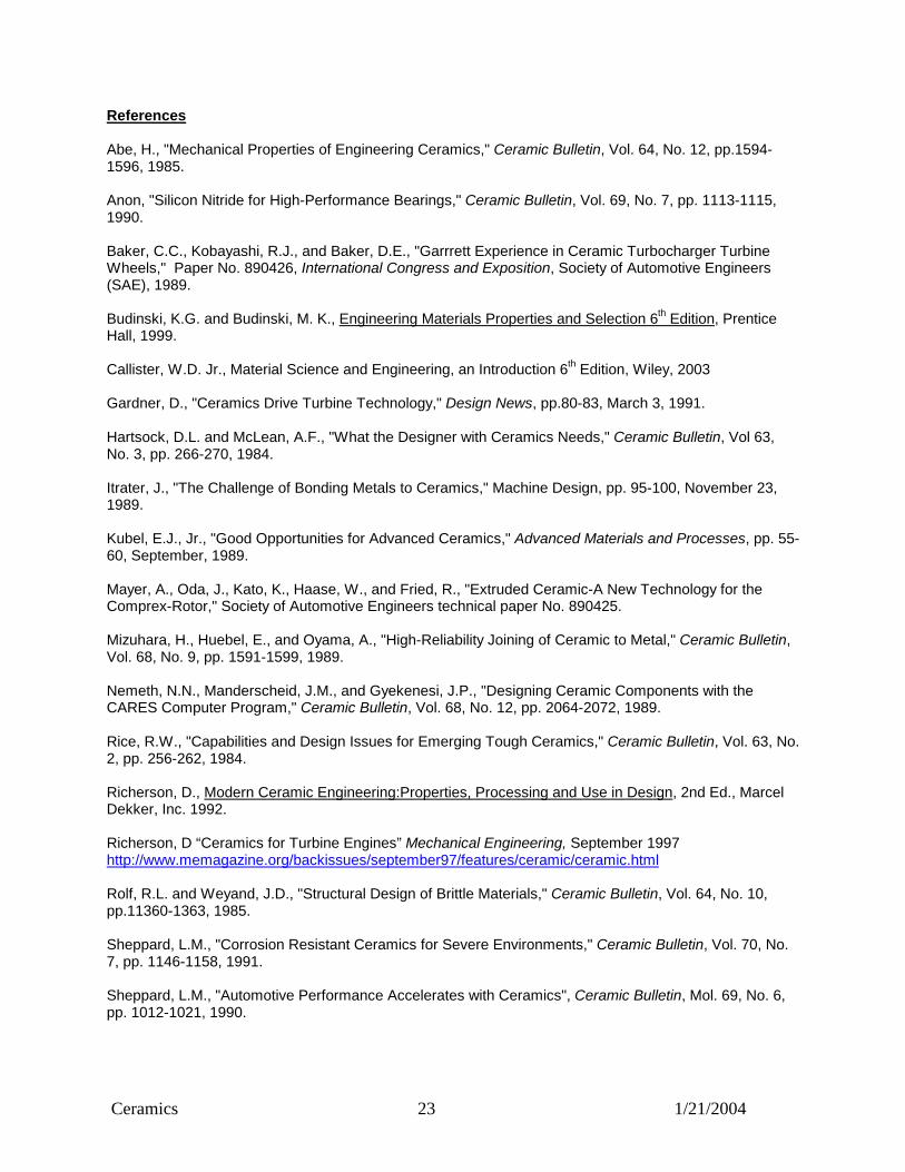
with units °C. Thus, a material with good thermal shock resistance will have high strength, low stiffness, and a low coefficient of thermal expansion. (Note that Pyrex has a very nearly zero expansion coefficient.) Other factors may also be relevant, such as a high thermal conductivity that tends to lower the thermal gradient. Figure 3.__ compares some advanced ceramics for thermal shock resistance. Note that other Thermal shock resistance parameters are used (Richerson, 1992 Table 3.1 Thermal shock resistance (Richerson, 1992)

Ceramics 22 1/21/2004
Dissimilar Materials If two materials with different coefficients of thermal expansion are bonded together, they will try to expand to different lengths. If they don’t separate, some stress will be carried at the interface. Consider a Si3N4 bonded to aluminum and lowered in temperature by 100°C. From Figure 1.__ we can see that the ceramic will only show about a tenth of the contraction of the aluminum. Thus the ceramic will end up in tension and the metal in compression. From static equilibrium we know that the forces at the interface have to be equal. If we also assume equal areas for the two parts, the stresses will be the same. Then the strains for each can be found from the stress strain relations through Young’s Modulus. In this case the ceramic can see a 10-15 ksi stress from that 100°C temperature change. Design implications – The designer is advised to try to match the coefficients of thermal expansion when mating metals and ceramics. From table 1.__ we see that zirconia is close to steel. Alternatively, the joint can be designed to allow for the geometry changes. This is explored in section 4. Summary
1. Thermal stresses only occur when expansion due to temperature change is constrained 2. For thermal shock you would like high strength low elastic modulus and low thermal expansion
coefficient 3. When joining materials that see a change in temperature, try to match thermal expansion
coefficients Caveats This work has been an introductory overview and has ignored many important issues in designing structural ceramics. The book _____ provides an excellent reviews by a number of companies regarding important design issues as they worked toward producing ceramic gas turbine engine components. Many of the articles contain a section on “lessons learned”. The beginning designer of ceramics would be well advised to learn from their experience.
Ceramics 23 1/21/2004
References Abe, H., "Mechanical Properties of Engineering Ceramics," Ceramic Bulletin, Vol. 64, No. 12, pp.1594-1596, 1985. Anon, "Silicon Nitride for High-Performance Bearings," Ceramic Bulletin, Vol. 69, No. 7, pp. 1113-1115, 1990. Baker, C.C., Kobayashi, R.J., and Baker, D.E., "Garrrett Experience in Ceramic Turbocharger Turbine Wheels," Paper No. 890426, International Congress and Exposition, Society of Automotive Engineers (SAE), 1989. Budinski, K.G. and Budinski, M. K., Engineering Materials Properties and Selection 6th Edition, Prentice Hall, 1999. Callister, W.D. Jr., Material Science and Engineering, an Introduction 6th Edition, Wiley, 2003 Gardner, D., "Ceramics Drive Turbine Technology," Design News, pp.80-83, March 3, 1991. Hartsock, D.L. and McLean, A.F., "What the Designer with Ceramics Needs," Ceramic Bulletin, Vol 63, No. 3, pp. 266-270, 1984. Itrater, J., "The Challenge of Bonding Metals to Ceramics," Machine Design, pp. 95-100, November 23, 1989. Kubel, E.J., Jr., "Good Opportunities for Advanced Ceramics," Advanced Materials and Processes, pp. 55-60, September, 1989. Mayer, A., Oda, J., Kato, K., Haase, W., and Fried, R., "Extruded Ceramic-A New Technology for the Comprex-Rotor," Society of Automotive Engineers technical paper No. 890425. Mizuhara, H., Huebel, E., and Oyama, A., "High-Reliability Joining of Ceramic to Metal," Ceramic Bulletin, Vol. 68, No. 9, pp. 1591-1599, 1989. Nemeth, N.N., Manderscheid, J.M., and Gyekenesi, J.P., "Designing Ceramic Components with the CARES Computer Program," Ceramic Bulletin, Vol. 68, No. 12, pp. 2064-2072, 1989. Rice, R.W., "Capabilities and Design Issues for Emerging Tough Ceramics," Ceramic Bulletin, Vol. 63, No. 2, pp. 256-262, 1984. Richerson, D., Modern Ceramic Engineering:Properties, Processing and Use in Design, 2nd Ed., Marcel Dekker, Inc. 1992. Richerson, D “Ceramics for Turbine Engines” Mechanical Engineering, September 1997 http://www.memagazine.org/backissues/september97/features/ceramic/ceramic.html Rolf, R.L. and Weyand, J.D., "Structural Design of Brittle Materials," Ceramic Bulletin, Vol. 64, No. 10, pp.11360-1363, 1985. Sheppard, L.M., "Corrosion Resistant Ceramics for Severe Environments," Ceramic Bulletin, Vol. 70, No. 7, pp. 1146-1158, 1991. Sheppard, L.M., "Automotive Performance Accelerates with Ceramics", Ceramic Bulletin, Mol. 69, No. 6, pp. 1012-1021, 1990.

Ceramics 24 1/21/2004
Wachtman, J.B., Jr., ed., Structural Ceramics - Treatise on Materials Science and Technology, Volume 29, Academic Press, Inc., Boston, 1989. Weibull, W., "A Statistical Distribution Function of Wide Applicability," Journal of Applied Mechanics, PP. 293-297, 1951. Weidmann, G., Lewis, P. and Reid, N., ed., Structural Materials, Butterworths, London, 1990. Yoshida, M. and Kokaji, A., "Firing Up the Future with Ceramic Engine Parts," Machine Design, pp. 58-63, October 26, 1989. Wenglarz, Richard A., Allison Ceramic Vane Efforts, Allison Engine Company, 1997 http://www.netl.doe.gov/publications/proceedings/97/97ats/ats_pdf/ATS5-5.PDF Yang, Y., Hadfield, M., “Rolling Contact Fatigue of Ceramics” 2002 http://www.sustainableengineering.org/publications/asm.pdf
Ceramics 25 1/21/2004
Sources of Information on Structural Ceramics
There are many sources of information on ceramics. One chapter in the ASM publication Ceramics and Glasses (listed below under Books) is titled "Guide to Information Sources and Standards and lists a number of sources. Shown below is a brief list of sources that may be a good place to start. Books: Structural Ceramics Treatise on Materials Science and Technology - Volume 29 Edited by John B. Wachtman, Jr. Academic Press, 1989 ISBN 0-12-341829-1 ($100) This is an excellent overview of structural ceramics, well referenced and with numerous examples. The chapter on design, written by MacLean and Hartsock, covers Weibull statistics and their practical use very well. An entire chapter is devoted to each of three families of ceramics, the silicon carbides, the silicon nitrides, and transformation toughened ceramics (primarily zirconia toughened ceramics). These chapters cover microstructure, processing, and properties. In addition their are chapters on ceramic composites and tribology. Engineered Materials Handbook - Ceramics and Glasses ASM Publications ASM International Materials Park, Ohio 44073-0002 216/338-5151 ISBN 0-87170-282-7 ($100) This is a large volume (over 1200 pages) that covers the field from manufacture of the powders, through design and manufacture of parts, to applications in electronics, aerospace, and housewares. The chapter on design by MacLean and Hartsock is adapted from Structural Ceramics. Other chapters useful to designers include one on advanced statistical concepts, one on probabilistic design with the CARES computer program, and several on design practices in specific areas such as gasoline engines. Information on ceramic composites can be found in Vol. 3 of the same series. Modern Ceramic Engineering: Properties and Use in Design, 2nd Ed. David Richerson Marcel Dekker, Inc. 1992 ($125.) This is an excellent description of properties (electrical, thermal, magnetic, optical, mechanical) and how they relate to processing and structure. It is also an excellent section on failure analysis of ceramics. The section on design is rather short. CeramicSource The American Ceramic Society, Inc. 757 Brooksedge Plaza Dr. Westerville, OH 43081-6136 Phone (614) 890-4700 Fax (614 899-6109 ($28 or free with membership) As the name implies, this is a source of information on the ceramic industry. Emphasis is on industrial suppliers of products and services. Included is a large section containing tables of technical data that have been gathered from recent literature. Introduction to Ceramics W.D. Kingery, et al. John Wiley and Sons, Inc. New York, NY
Ceramics 26 1/21/2004
This is a widely referenced and highly regarded introduction to the material science of ceramics, and is a good place to start for those who wish to learn about the microstructure and how it affects properties. Reliability and Life Testing Analysis L.J. Bain This provides an introduction to the use of Weibull statistics with examples that are mostly in the life testing area. This is not easily readable without a fairly strong background in statistics. Other texts in reliability and life testing also cover Weibull statistics. Periodicals and Journals: The American Ceramic Society publishes: The American Ceramic Society Bulletin, a good source of general information about ceramics. The Ceramic Engineering and Science Proceedings, articles from conference proceedings. The Journal of the American Ceramic Society, articles on ceramic research. Information Sources: The American Ceramic Society http://www.acers.org/ (address listed above) ACerS, an international association that provides the latest technical, scientific and educational information to its Members and others in the ceramics and related materials field, structures its services, staff and capabilities to meet the needs of the ceramics community, related fields, and the general public. They also list significant sources http://www.ceramics.org/resources.asp and ASM International http://www.asminternational.org (address listed above) This society deals with all kinds of materials including metals, ceramics, and composites and publishes a variety of books and journals, some of which deal with ceramics. Ceramics Division of NIST http://www.ceramics.nist.gov/ National Institute of Standards and Technology (NIST) Department of Commerce Washington D.C. 20234 (309) 921-3181 Public Information Office (301) 921-2318 Technical Information and Publications Formerly the National Bureau of Standards (NBS), the NIST is concerned with national competitiveness in ceramics. They do research, write standards and are a source of information on properties and processing. United States Advance Ceramic Association USACA is the premier association that champions the common business interests of the advanced ceramic producer and end-user industries. USACA was formed in 1985 to facilitate the commercialization of the United States’ advanced ceramics industry and quickly became the leading voice of the advanced ceramics industry before the U.S. Congress and federal agencies. http://www.advancedceramics.org/ Engineering Index http://www.engineeringvillage2.org/ Engineering Information Inc. 345 E. 47th Street New York, NY 10017-2387 (800) 221-1044 Available in most technical libraries, this index covers literature from many areas of engineering.
Ceramics 27 1/21/2004
Software: WinSMITH Weibull “WinSMITH Weibull software by Fulton Findings produces Weibull, lognormal, Gumbel (both upper and lower) distribution, and normal probability-plots to analyze data used for making reliability improvements. It operates in a Windows 95, Windows NT, Windows XP, and Windows 2000 operating environment.” http://www.barringer1.com/wins.htm Weibull++6 Part of ReliaSoft's suite of reliability software products, Weibull++ performs life data analyses utilizing multiple lifetime distributions, including all forms of the Weibull distribution, with a clear and concise interface geared toward reliability engineering. http://www.reliasoft.com/Weibull/ CARES/LIFE “CARES/LIFE predicts the probability of failure of a monolithic ceramic component as a function of service time. It assesses the risk that the component will fracture prematurely as a result of subcritical crack growth. The effect of proof testing components prior to service is also considered. CARES/LIFE is coupled to commercially available finite-element programs such as ANSYS, ABAQUS, MSC/NASTRAN, and COSMOS/M. It also retains all of the capabilities of the previous CARES code, which include fast-fracture component reliability evaluation and Weibull parameter estimation from inert strength (without SCG contributing to failure) specimen data. CARES/LIFE can estimate parameters that characterize SCG from specimen data as well.” (quoted from Open Channel Foundation Website listed below). It was developed by NASA and is in the public domain.
The homepage for the software is http://www.grc.nasa.gov/WWW/LPB/cares/life/ and a beta version is available (in the USA) from Primary Contact: Noel N. Nemeth Phone: (216) 433-3215
A nice overview of CARES/Life from the GE Research and Development Center by M. Chati, A Kaya, and C. Johnson is at http://www.crd.ge.com/cooltechnologies/pdf/2001crd103.pdf Another is from the Open Channel Foundation is the outlet for some NASA code and who sells the source code for $800. http://www.openchannelfoundation.org/projects/CARES_LIFE/ CARES/CREEP There is another version of CARES for Creep prediction. It is described in the Nasa Tech brief listed below as “CARES/CREEP utilizes the finite-element heat-transfer and nonlinear-stress-analysis capabilities of ANSYS to obtain temperature and stress distributions in a ceramic component. … The creep life of a component is discretized into short time steps, during each of which the stress and strain distributions are assumed constant. http://www.nasatech.com/Briefs/June00/LEW16917.html You can get more information at the CARES/LIFE homepage.

Ceramics 28 1/21/2004
Exercise 1: We are considering replacing the metal balls in a ball bearing with ceramic balls (specifically, silicon nitride). Is this a good idea? One solution To answer the question “Is it a good idea?” we need some criteria for judgement. We may say that the role of the engineer is to make products that
a) don’t hurt anyone b) make money c) work satisfactorily
Our criteria will then be: Will the bearing be safer, more profitable, and/or work better. Our basis for judgement comes from what we can infer from what we know. At his point we know something about the properties of ceramics relative to metals, so we will start there. Property of ceramic - relative to steel
Advantage for bearing Disadvantage for bearing
Higher Tmelt Higher operating temperature – therefore higher speeds if ball temp is limiting factor
none
Lower Density Lower linear and rotational inertia – spin up faster and maintain speed with less power
none
Higher Young’s Modulus Less ball deformation, tighter overall tolerance on bearing
Higher stress on race (smaller contact area
Lower thermal conductivity Less able to move heat away from bearing – slower speeds
Ductility Balls are loaded in compression – less concern (good reason to use metal races)
Concern for impact loads and ball fracture
Hardness Lower friction – less heat - faster operating speeds, lower losses
Potential for more wear of race
Cost If life is significantly higher, additional cost may be ok.
Harder to make – higher initial cost
Now we have some specific questions for the vendor or tests in the laboratory. We can investigate:
• cost vs. life • reliability in impact on ball and fatigue of the races • change in operating losses and maximum rated speed and load
Shown below is one vendor’s comment about changing to ceramic balls “A frequently asked question regarding hybrid bearing performance is the load capability which affects the L10 Life Calculation of a hybrid bearing. This is an important issue and has been given significant attention over the past several years. Silicon nitride ball is much stiffer than a steel ball and thus, the contact patch on the raceway is much smaller. For any given load, this means that the stress in the raceway at the contact patch is increased and, "theoretically," the L10life will be reduced in a hybrid bearing. Indeed applications that require bearings to perform at near maximum load levels (when bearings, for example) demonstrate lower life characteristics when a hybrid bearing is substituted for a steel bearing because the fail from fatigue. Machine tool bearings, however, rarely approach maximum load conditions making the hybrid bearing a practical substitute for a steel bearing in any application. Further, bearing designers can adjust the raceway curvatures and the number of balls in a hybrid bearing to improve the load carrying capability of the bearing.” http://www.cerbec.com/HybridBearing/Load.asp

Ceramics 29 1/21/2004
This chart show another vendor’s advertising for ceramic hybrid bearings.
http://www.bearingworks.com/materials.htm#ceramics

Ceramics 30 1/21/2004
Exercise 2: Suppose we wish to replace the metal head of a total hip replacement with a ceramic head. Would this be better? Following our example with the bearing (exercise 1) we are answering the questions: Is the ceramic implant safer, more profitable, and/or better functioning? Property of ceramic - relative to metal
Advantage for hip implant Disadvantage for implant
Higher Tmelt none none Lower Density Minimal difference to patient none Higher Young’s Modulus Hip ball doesn’t mate with bone Worse match with bone Lower thermal conductivity None None Ductility None potential for fracture Hardness Lower wear longer life None Corrosion Resistance Better biocompatibility, better life None Cost Not that important in assembly
For medical devices an improvement in performance is the driver for use.
Shown below is an excerpt fro the web site of a law firm regarding one ceramic head implant. This kind of thing puts a huge damper on the market. Performance has to be overwhelmingly better for a surgeon to want to stick his/her neck out. Note that the recall applies only to certain batches of zirconia, not alumina.
The St. Gobain Ceramic Hip Recall
On September 14, 2001, the U.S. Food and Drug Administration (the "FDA") announced that eight U.S. firms that make hip implants are, or will be, voluntarily recalling certain hip implants due to the possible fracturing of a component of their artificial hips that was produced by the same company. The component, known as the zirconia ceramic femoral head, was recalled by its French manufacturer, St. Gobain Desmarquest, on August 14, 2001 because it was fracturing at a higher rate than expected.
The zirconia ceramic femoral head is the implant ball portion of the artificial hip that connects the implant stem to the pelvis.
In the U.S., the FDA has received at least 14 reports of fracturing of hip implants containing the zirconia ceramic femoral head. The manufacturer, St. Gobain Desmarquest, identified a total of 76 failures worldwide of the product. St. Gobain Desmarquest has not stated the cause of the defect. Instead, it is conducting an investigation focusing on whether the ceramic material used was not properly manufactured or whether other elements, including the design of the component, have led to the fractures.
It is not expected that all the recalled hips will break, and the FDA does not recommend surgery for patients whose implant has not failed. But there is also no way to predict which hip will fracture. Patients should "be aware this increased risk exists," said FDA medical officer Dr. Dan Schultz. "If they have any symptoms whatsoever, they need to get in to see their physician as quickly as possible. Don't assume ... it's something that is just going to go away."

Ceramics 31 1/21/2004
Symptoms of a fractured zirconia ceramic femoral head include hip pain, a sensation of grinding or limitation of motion. The fracture is sometimes preceded by an audible pop. The at-risk hips tend to break between 19 and 28 months after they have been implanted.
Distribution of the St. Gobain Ceramic Femoral Head
St. Gobain Desmarquest distributes ceramic femoral heads worldwide to most of the orthopedic industry, including:
• Apex Surgical
• Biomet
• DePuy Orthopedics
• Encore Orthopedics
• Osteoimplant Technology
• Smith & Newphew
• Stryker Howmedica
• Zimmer
Hip Implant Patients Whose Artificial
Hips Have Failed
Click here to contact Lieff Cabraser
It is estimated that 6 percent of the 150,000 to 200,000 persons that undergo hip replacement surgery each year receive an artificial hip containing the zirconia ceramic femoral head. The recall applies to zirconia ceramic femoral heads manufactured since January 1998. To read the complete FDA Press Release, click here.
Legal Rights of Hip Replacement Recall Patients
If you have a defective hip implant, you are not obligated to accept any "settlement" offered by the manufacturer without first consulting an attorney.
In most states, the claims that can be asserted against medical device companies that have produced defective hip implants include strict liability for a defective product, breach of warranty, negligence, misrepresentation and strict liability for failure to warn recipients of the defect Damages sought against these companies can often include damage for:
1. Past and future physical pain and suffering, mental anguish and physical impairment;
2. Past and future medical expenses associated with the allegedly defective hip implant; and
3. Past and future loss of earnings and/or earning capacity
http://www.hipimplantlaw.com/

Ceramics 32 1/21/2004


![MARINE DIESELS WORKING CYCLE MONITORING ON THE BASE … diesels … · engines of Wartsila RT-flex and MAN ME types. Fig. 1. IMES GmbH pressure sensor [1] These types of diesels need](https://static.fdocuments.net/doc/165x107/5eabde67f5ecbf463c2ed6a2/marine-diesels-working-cycle-monitoring-on-the-base-diesels-engines-of-wartsila.jpg)