Intimate Communications Hub - Data … Communications Hub Interface Specification Page 5 of 56...
56
Intimate Communications Hub Interface Specification Page 1 of 56 Intimate Communications Hub Interface Specification 28 February 2014 Intimate Communications Hub Interface Specification Author DCC V1.0 28 February 2014
Transcript of Intimate Communications Hub - Data … Communications Hub Interface Specification Page 5 of 56...
Intimate Communications Hub
Interface Specification
Page 1 of 56 Intimate Communications Hub Interface Specification
28 February 2014
Intimate Communications Hub
Interface Specification
Author
DCC
V1.0
28 February 2014

Intimate Communications Hub
Interface Specification
Page 2 of 56 Intimate Communications Hub Interface Specification
28 February 2014
Contents
Framework............................................................................................................. 6 Part A
Introduction ......................................................................................................... 6 A1.0
Scope .................................................................................................................. 6 A2.0
A2.1 In-Scope .......................................................................................................... 6
A2.2 Out of Scope .................................................................................................... 7
References to Standards ..................................................................................... 7 A3.0
Detail of Products ................................................................................................ 9 A4.0
Glossary ............................................................................................................ 10 A5.0
Revision history ................................................................................................. 12 A6.0
Mechanical Interface ........................................................................................... 14 Part B
General requirements for mechanical interface ................................................. 14 B1.0
B1.1 Details of mechanical dimensions .................................................................. 14
B1.2 Reference drawing of the Host ....................................................................... 15
B1.3 Reference drawing of the Device interface ..................................................... 17
B1.4 DC and signalling connector details ............................................................... 18
B1.5 Ingress Protection rating ................................................................................ 19
B1.6 Physical security ............................................................................................ 19
B1.7 Interface mechanical performance ................................................................. 20
B1.8 General mechanical and environmental requirements for Hosts and Devices 20
Specific requirements for mechanical interface.................................................. 21 B2.0
B2.1 Specific requirements for Communications Hubs ........................................... 21
B2.2 Specific requirements for single phase ESMEs .............................................. 21
B2.3 Specific requirements for twin element ESMEs .............................................. 21
B2.4 Specific requirements for polyphase ESMEs ................................................. 21
B2.5 Specific requirements for Communication Hub Hot Shoes ............................. 22
B2.6 Specific requirements for Blanking Plates ...................................................... 22
B2.7 Specific requirements for Cradles .................................................................. 22
Intimate Communications Hub
Interface Specification
Page 3 of 56 Intimate Communications Hub Interface Specification
28 February 2014
B2.8 Specific requirements for Adaptors ................................................................ 22
Optional Features and Information .................................................................... 23 B3.0
B3.1 Optional AC signalling connector ................................................................... 23
B3.2 For information only ....................................................................................... 24
DC Power ............................................................................................................. 26 Part C
Requirements for Provision of DC Power .......................................................... 26 C1.0
C1.1 Details of the mechanical DC connector ........................................................ 26
C1.2 DC power management ................................................................................. 26
C1.3 EMC requirements on DC power supply ........................................................ 31
C1.4 DC Safety Considerations – Intimate Connection .......................................... 31
C1.5 DC Safety Consideration – External Metal – Device ...................................... 32
Specific requirements for the provision of DC power ......................................... 32 C2.0
C2.1 Specific requirements for Communications Hubs ........................................... 32
C2.2 Specific requirements for single phase ESMEs .............................................. 34
C2.3 Specific requirements for single phase, twin element ESMEs ........................ 34
C2.4 Specific requirements for polyphase ESMEs ................................................. 34
C2.5 Specific requirements for Communication Hub Hot Shoes ............................. 34
C2.6 Specific requirements for Adaptors and Cradles ............................................ 34
Other DC Power Considerations (For information only) ..................................... 35 C3.0
C3.1 Considerations for fusing Lsupply, Lload, and DC connections ............................ 35
C3.2 Power Supply References.............................................................................. 36
Optional AC Signalling Provision ...................................................................... 37 Part D
Introduction ....................................................................................................... 37 D1.0
D1.1 Purpose ......................................................................................................... 37
D1.2 Conditions for use of AC signalling ................................................................ 37
Requirements for the provision of AC Signalling ................................................ 38 D2.0
D2.1 Connector Details .......................................................................................... 38
D2.2 Safety Requirements ..................................................................................... 39
Intimate Communications Hub
Interface Specification
Page 4 of 56 Intimate Communications Hub Interface Specification
28 February 2014
D2.3 PLC Coupling requirements ........................................................................... 39
Specific requirements for AC Signalling Connections ........................................ 40 D3.0
D3.1 Specific requirements for Communications Hubs ........................................... 40
D3.2 Specific requirements for Blanking Plates ...................................................... 40
D3.3 Specific requirements for single phase ESMEs .............................................. 40
D3.4 Specific requirements for twin element ESMEs .............................................. 40
D3.5 Specific requirements for polyphase ESMEs ................................................. 40
D3.6 Specific requirements for Communication Hub Hot Shoes ............................. 40
D3.7 Specific requirements for Cradles .................................................................. 40
D3.8 Specific requirements for Adaptors ................................................................ 41
Digital Signalling Pins ........................................................................................ 42 Part E
Introduction ....................................................................................................... 42 E1.0
E1.1 Purpose ......................................................................................................... 42
E1.2 Pin Positioning ............................................................................................... 42
E1.3 Pin Definitions ................................................................................................ 43
General requirements for Digital Signalling Pins ................................................ 44 E2.0
E2.1 Performance Requirements for Open-collector Outputs ................................. 44
E2.2 EMC Requirements on Data Lines ................................................................. 44
Specific requirements for Digital Signalling Pins ................................................ 45 E3.0
E3.1 Specific requirements for Communications Hubs ........................................... 45
E3.2 Specific requirements for Blanking Plates ...................................................... 46
E3.3 Specific requirements for single phase ESMEs .............................................. 46
E3.4 Specific requirements for twin element ESMEs .............................................. 48
E3.5 Specific requirements for polyphase ESMEs ................................................. 48
E3.6 Specific requirements for Communication Hub Hot Shoes ............................. 48
E3.7 Specific requirements for Cradles .................................................................. 49
E3.8 Specific requirements for Adaptors ................................................................ 50
RF Implementation .............................................................................................. 51 Part F

Intimate Communications Hub
Interface Specification
Page 5 of 56 Intimate Communications Hub Interface Specification
28 February 2014
Design Considerations ...................................................................................... 51 F1.0
F1.1 Rationale ....................................................................................................... 51
F1.2 Antenna Placement........................................................................................ 51
F1.3 Future Considerations .................................................................................... 52
Testing Methodology for Hosts .......................................................................... 52 F2.0
F2.1 Equipment requirements ................................................................................ 52
F2.2 RF Isolation Recommendations ..................................................................... 54
F2.3 Test Setup Requirements .............................................................................. 54
F2.4 Determining levels ......................................................................................... 54
Recommendations for ESME transmission on the HAN .................................... 55 F3.0
Security ............................................................................................................ 56 Part G
Physical security ................................................................................................ 56 G1.0
G1.1 Mechanical security ....................................................................................... 56
G1.2 Tamper detection ........................................................................................... 56
G1.3 Scope of secure perimeter ............................................................................. 56
Out of scope areas ............................................................................................ 56 G2.0
Intimate Communications Hub
Interface Specification
Page 6 of 56 Intimate Communications Hub Interface Specification
28 February 2014
Framework Part A
Introduction A1.0
The Intimate Communications Hub Interface (ICHI) specification defines a common interface between Intimate Communications Hubs (ICH) and Smart Meters which will be deployed for the GB Smart Metering Implementation Programme. At the time of writing, only Electricity Smart Metering Equipment (ESME) are appropriate to provide the capability defined in ICHIS, as well as Communication Hub Hot Shoes and Cradles which can convert an ICH into a Stand-Alone Communications Hub (SACH). Communication Hub Hot Shoes are the ICHI suitable for use with Gas Smart Metering Equipment (GSME). The document is structured in such a way to allow future expansion to include other devices.
The ICHI specification defines the mandatory features required to ensure that an ICH can be used with any ICHIS compliant Host, as well as defining features reserved for future use or for CSP specific implementation.
This specification has been produced by and is owned and maintained by SmartDCC Ltd. It is published on the SmartDCC Ltd website, and is free to access and use. Once published, the specification is managed under the SmartDCC Ltd’s change control process.
The specification shall be reviewed as a minimum by SmartDCC Ltd on an annual basis to ensure it remains fit for purpose and use. Outside of the annual review, if a user of the specification should identify any changes or updates that are required, please contact SmartDCC Ltd via email to [email protected] detailing the proposed change and accompanying rationale for the change. Should proposed changes be identified by either the annual review process or via a formal change request the document will be revised by SmartDCC Ltd and any proposed changes consulted with SEC (Smart Energy Code) parties. Where the specification is updated following this process it will be re-published via the SmartDCC Ltd’s website.
Scope A2.0
A2.1 In-Scope
This document will define the interfaces for the:
Intimate Communications Hub and similar Devices defined in 0 using the same interface; and
ESME and similar Hosts defined in 0 using the same interface.
The definitions cover the:
Mechanical interface;
Power supply provided from a Host to a Communications Hub;
Tamper detection; and
External dependencies and recommended good practice.
This document also provides descriptions for interoperability testing required to ensure compliance, including testing for RF interference between the ESME and CH.
Intimate Communications Hub
Interface Specification
Page 7 of 56 Intimate Communications Hub Interface Specification
28 February 2014
A2.2 Out of Scope
The items below are outside the scope of this specification.
All functionality otherwise provided by the CH
All functionality otherwise provided by the ESME
Protocols for communications and data transfer including security between a ESME and a CH
Requirements of protective covers used for covering the ICHI during shipping which will not be left in place by installers (as opposed to Blanking Plates used throughout the rest of this document which are intended to stay affixed to a Host after Installation).
Aesthetics of the ESME and the CH unit
Physical dimensions of the ESME and the CH that are not otherwise covered or prohibited by this specification
HMI (Human Machine Interface) of Hosts or Devices
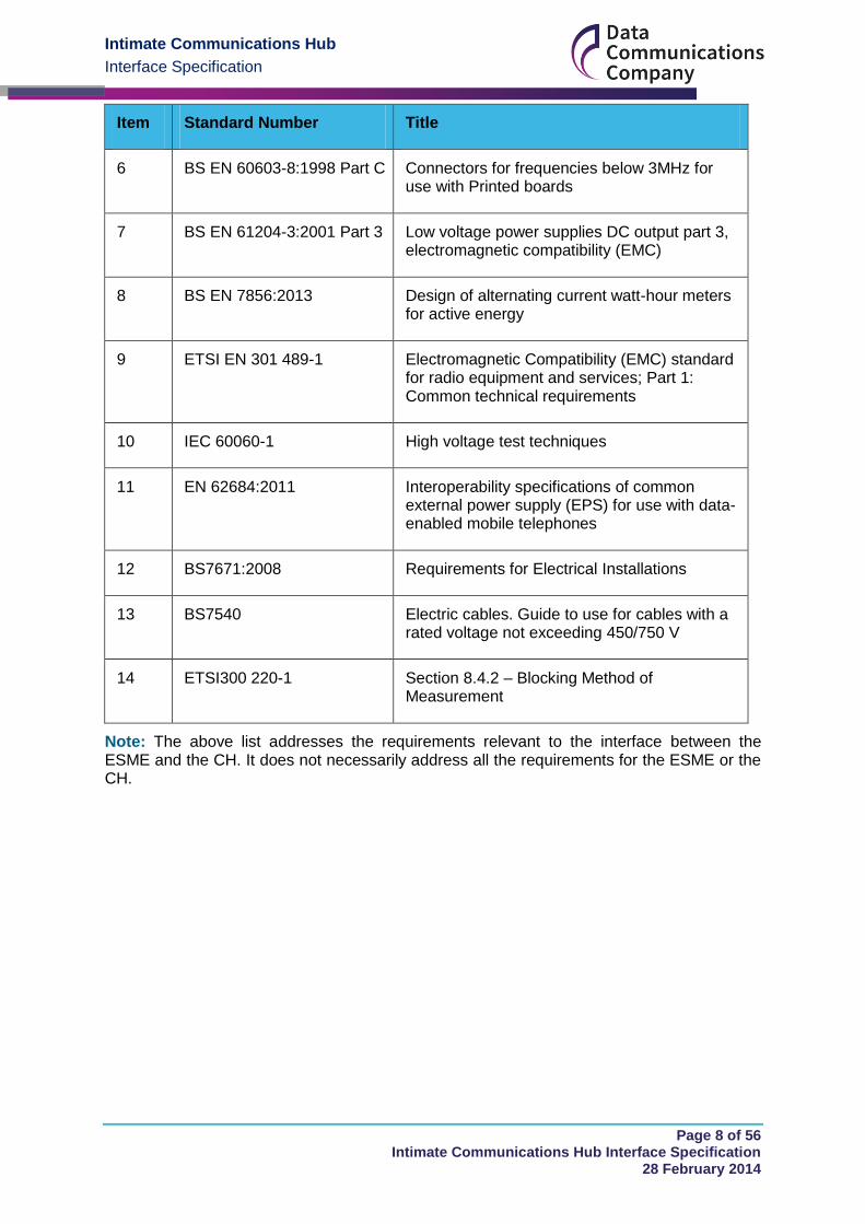
References to Standards A3.0
Item Standard Number Title
1 BS EN 50470-1 Electricity metering equipment (a.c.) – Part 1: General requirements, tests and test conditions – Metering equipment (class indexes A, B and C)
2 BS EN 50470-3 Electricity metering equipment (a.c.) – Part 3: Particular requirements – Static meters for active energy (class indexes A, B and C)
3 Proposed IEC 62052-31
Electricity metering equipment (AC) – General requirements, tests and test conditions – Part 31: Safety Requirements
NOTE: this document is under development and is currently at CDV stage in November 2013
4 BS EN 55022 Information technology equipment. Radio disturbance characteristics. Limits and methods of measurement
5 BS EN 60529 Specification for degrees of protection provided by enclosures (IP code)
Intimate Communications Hub
Interface Specification
Page 8 of 56 Intimate Communications Hub Interface Specification
28 February 2014
Item Standard Number Title
6 BS EN 60603-8:1998 Part C Connectors for frequencies below 3MHz for use with Printed boards
7 BS EN 61204-3:2001 Part 3 Low voltage power supplies DC output part 3, electromagnetic compatibility (EMC)
8 BS EN 7856:2013 Design of alternating current watt-hour meters for active energy
9 ETSI EN 301 489-1 Electromagnetic Compatibility (EMC) standard for radio equipment and services; Part 1: Common technical requirements
10 IEC 60060-1 High voltage test techniques
11 EN 62684:2011 Interoperability specifications of common external power supply (EPS) for use with data-enabled mobile telephones
12 BS7671:2008 Requirements for Electrical Installations
13 BS7540 Electric cables. Guide to use for cables with a rated voltage not exceeding 450/750 V
14 ETSI300 220-1 Section 8.4.2 – Blocking Method of Measurement
Note: The above list addresses the requirements relevant to the interface between the ESME and the CH. It does not necessarily address all the requirements for the ESME or the CH.
Intimate Communications Hub
Interface Specification
Page 9 of 56 Intimate Communications Hub Interface Specification
28 February 2014
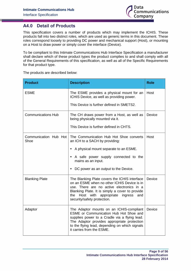
Detail of Products A4.0
This specification covers a number of products which may implement the ICHIS. These products fall into two distinct roles, which are used as generic terms in this document. These roles correspond loosely to providing DC power and mechanical support (Host), or mounting on a Host to draw power or simply cover the interface (Device).
To be compliant to this Intimate Communications Hub Interface Specification a manufacturer shall declare which of these product types the product complies to and shall comply with all of the General Requirements of this specification, as well as all of the Specific Requirements for that product type.
The products are described below:
Product Description Role
ESME The ESME provides a physical mount for an ICHIS Device, as well as providing power.
This Device is further defined in SMETS2.
Host
Communications Hub The CH draws power from a Host, as well as being physically mounted via it.
This Device is further defined in CHTS.
Device
Communication Hub Hot Shoe
The Communication Hub Hot Shoe converts an ICH to a SACH by providing:
A physical mount separate to an ESME.
A safe power supply connected to the mains as an input.
DC power as an output to the Device.
Host
Blanking Plate The Blanking Plate covers the ICHIS interface on an ESME when no other ICHIS Device is in use. There are no active electronics in a Blanking Plate. It is simply a cover to provide the Host with appropriate ingress and security/safety protection.
Device
Adaptor The Adaptor mounts on an ICHIS-compliant ESME or Communication Hub Hot Shoe and supplies power to a Cradle via a flying lead. The Adaptor provides appropriate protection to the flying lead, depending on which signals it carries from the ESME.
Device
Intimate Communications Hub
Interface Specification
Page 10 of 56 Intimate Communications Hub Interface Specification
28 February 2014
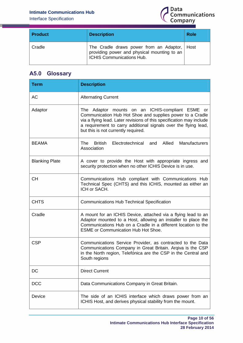
Product Description Role
Cradle The Cradle draws power from an Adaptor, providing power and physical mounting to an ICHIS Communications Hub.
Host
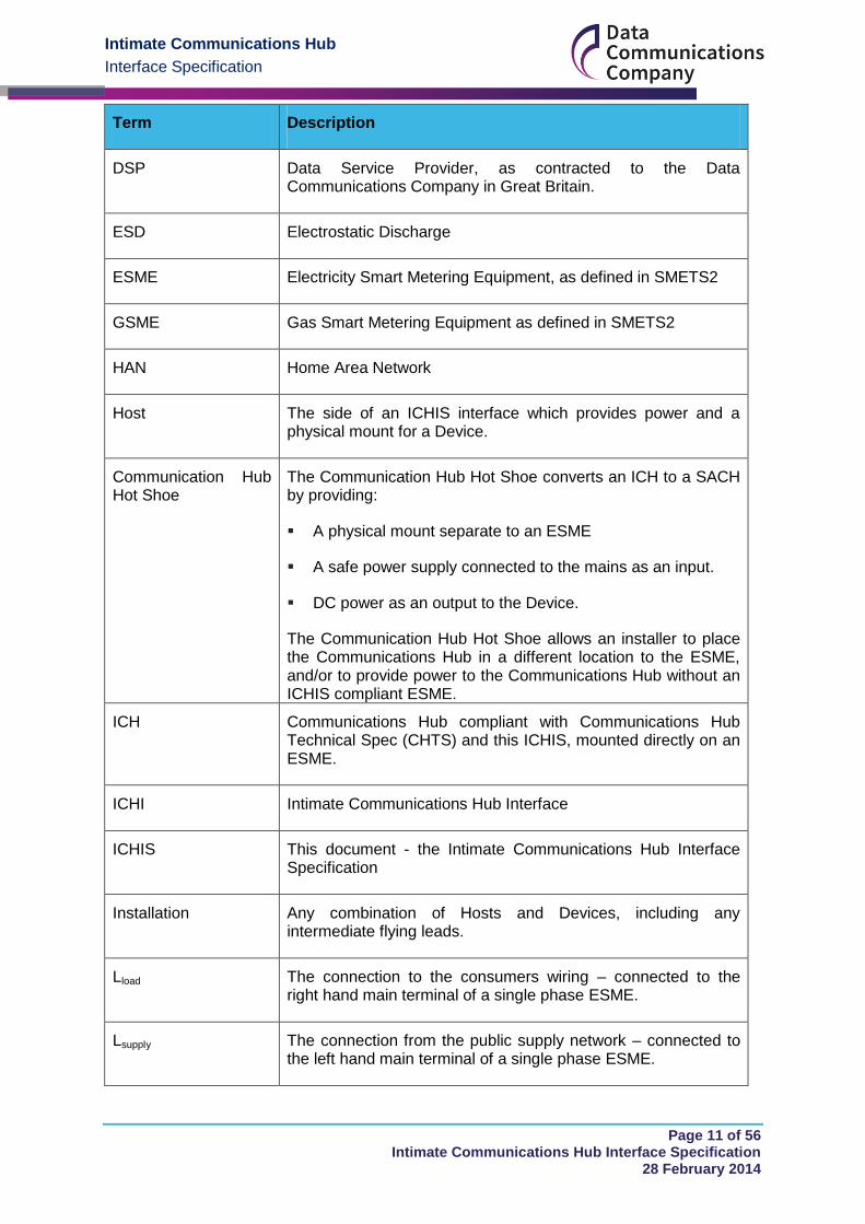
Glossary A5.0
Term Description
AC Alternating Current
Adaptor The Adaptor mounts on an ICHIS-compliant ESME or Communication Hub Hot Shoe and supplies power to a Cradle via a flying lead. Later revisions of this specification may include a requirement to carry additional signals over the flying lead, but this is not currently required.
BEAMA The British Electrotechnical and Allied Manufacturers Association
Blanking Plate A cover to provide the Host with appropriate ingress and security protection when no other ICHIS Device is in use.
CH Communications Hub compliant with Communications Hub Technical Spec (CHTS) and this ICHIS, mounted as either an ICH or SACH.
CHTS Communications Hub Technical Specification
Cradle A mount for an ICHIS Device, attached via a flying lead to an Adaptor mounted to a Host, allowing an installer to place the Communications Hub on a Cradle in a different location to the ESME or Communication Hub Hot Shoe.
CSP Communications Service Provider, as contracted to the Data Communications Company in Great Britain. Arqiva is the CSP in the North region, Telefónica are the CSP in the Central and South regions
DC Direct Current
DCC Data Communications Company in Great Britain.
Device The side of an ICHIS interface which draws power from an ICHIS Host, and derives physical stability from the mount.
Intimate Communications Hub
Interface Specification
Page 11 of 56 Intimate Communications Hub Interface Specification
28 February 2014
Term Description
DSP Data Service Provider, as contracted to the Data Communications Company in Great Britain.
ESD Electrostatic Discharge
ESME Electricity Smart Metering Equipment, as defined in SMETS2
GSME Gas Smart Metering Equipment as defined in SMETS2
HAN Home Area Network
Host The side of an ICHIS interface which provides power and a physical mount for a Device.
Communication Hub Hot Shoe
The Communication Hub Hot Shoe converts an ICH to a SACH by providing:
A physical mount separate to an ESME
A safe power supply connected to the mains as an input.
DC power as an output to the Device.
The Communication Hub Hot Shoe allows an installer to place the Communications Hub in a different location to the ESME, and/or to provide power to the Communications Hub without an ICHIS compliant ESME.
ICH Communications Hub compliant with Communications Hub Technical Spec (CHTS) and this ICHIS, mounted directly on an ESME.
ICHI Intimate Communications Hub Interface
ICHIS This document - the Intimate Communications Hub Interface Specification
Installation Any combination of Hosts and Devices, including any intermediate flying leads.
Lload The connection to the consumers wiring – connected to the right hand main terminal of a single phase ESME.
Lsupply The connection from the public supply network – connected to the left hand main terminal of a single phase ESME.
Intimate Communications Hub
Interface Specification
Page 12 of 56 Intimate Communications Hub Interface Specification
28 February 2014
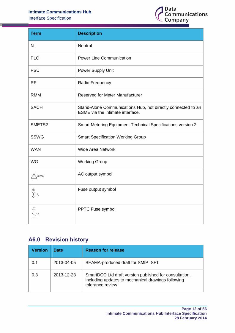
Term Description
N Neutral
PLC Power Line Communication
PSU Power Supply Unit
RF Radio Frequency
RMM Reserved for Meter Manufacturer
SACH Stand-Alone Communications Hub, not directly connected to an ESME via the intimate interface.
SMETS2 Smart Metering Equipment Technical Specifications version 2
SSWG Smart Specification Working Group
WAN Wide Area Network
WG Working Group
AC output symbol
Fuse output symbol
PPTC Fuse symbol
Revision history A6.0
Version Date Reason for release
0.1 2013-04-05 BEAMA-produced draft for SMIP ISFT
0.3 2013-12-23 SmartDCC Ltd draft version published for consultation, including updates to mechanical drawings following tolerance review

Intimate Communications Hub
Interface Specification
Page 13 of 56 Intimate Communications Hub Interface Specification
28 February 2014
Version Date Reason for release
1.0 2014-02-28 Initial SmartDCC Ltd iteration following consultation feedback
Intimate Communications Hub
Interface Specification
Page 14 of 56 Intimate Communications Hub Interface Specification
28 February 2014
Mechanical Interface Part B
General requirements for mechanical interface B1.0
All dimensions within this ICHI Specification are in millimetres (mm).
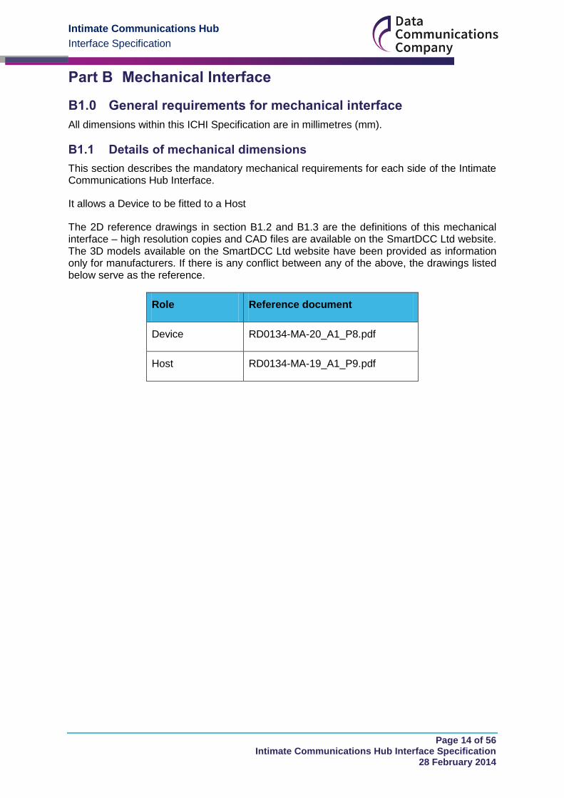
B1.1 Details of mechanical dimensions
This section describes the mandatory mechanical requirements for each side of the Intimate Communications Hub Interface.
It allows a Device to be fitted to a Host
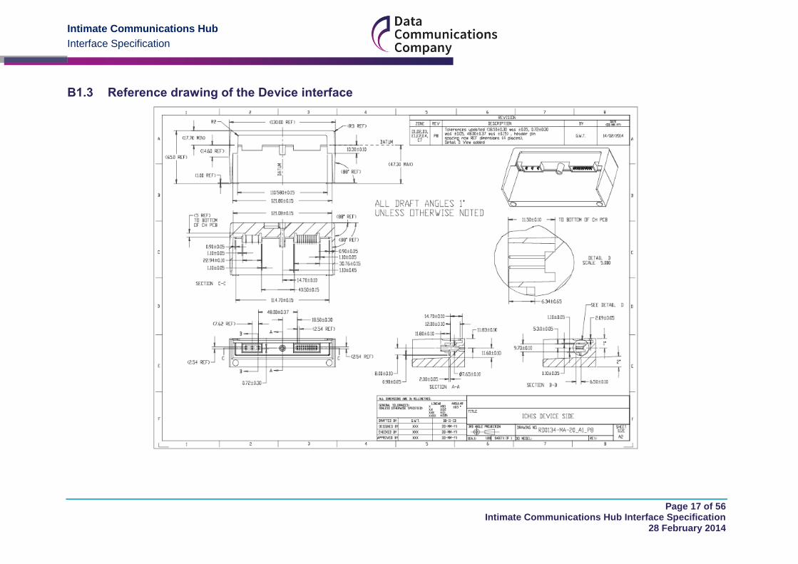
The 2D reference drawings in section B1.2 and B1.3 are the definitions of this mechanical interface – high resolution copies and CAD files are available on the SmartDCC Ltd website. The 3D models available on the SmartDCC Ltd website have been provided as information only for manufacturers. If there is any conflict between any of the above, the drawings listed below serve as the reference.
Role Reference document
Device RD0134-MA-20_A1_P8.pdf
Host RD0134-MA-19_A1_P9.pdf
Intimate Communications Hub
Interface Specification
Page 15 of 56 Intimate Communications Hub Interface Specification
28 February 2014
B1.2 Reference drawing of the Host

Intimate Communications Hub
Interface Specification
Page 16 of 56 Intimate Communications Hub Interface Specification
28 February 2014
Intimate Communications Hub
Interface Specification
Page 17 of 56 Intimate Communications Hub Interface Specification
28 February 2014
B1.3 Reference drawing of the Device interface
Intimate Communications Hub
Interface Specification
Page 18 of 56 Intimate Communications Hub Interface Specification
28 February 2014
B1.4 DC and signalling connector details
B1.4.1 Specific requirements for Devices
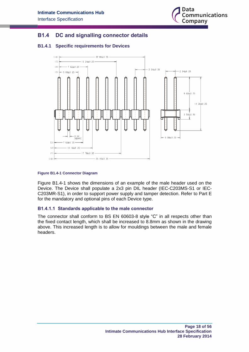
Figure B1.4-1 Connector Diagram
Figure B1.4-1 shows the dimensions of an example of the male header used on the Device. The Device shall populate a 2x3 pin DIL header (IEC-C203MS-S1 or IEC-C203MR-S1), in order to support power supply and tamper detection. Refer to Part E for the mandatory and optional pins of each Device type.
B1.4.1.1 Standards applicable to the male connector
The connector shall conform to BS EN 60603-8 style “C” in all respects other than the fixed contact length, which shall be increased to 8.8mm as shown in the drawing above. This increased length is to allow for mouldings between the male and female headers.
Intimate Communications Hub
Interface Specification
Page 19 of 56 Intimate Communications Hub Interface Specification
28 February 2014
B1.4.2 Specific Requirements for Hosts
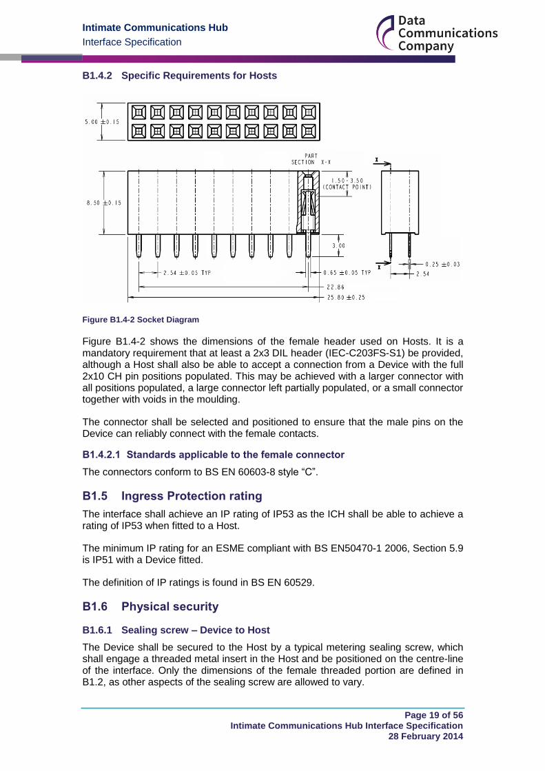
Figure B1.4-2 Socket Diagram
Figure B1.4-2 shows the dimensions of the female header used on Hosts. It is a mandatory requirement that at least a 2x3 DIL header (IEC-C203FS-S1) be provided, although a Host shall also be able to accept a connection from a Device with the full 2x10 CH pin positions populated. This may be achieved with a larger connector with all positions populated, a large connector left partially populated, or a small connector together with voids in the moulding.
The connector shall be selected and positioned to ensure that the male pins on the Device can reliably connect with the female contacts.
B1.4.2.1 Standards applicable to the female connector
The connectors conform to BS EN 60603-8 style “C”.
B1.5 Ingress Protection rating
The interface shall achieve an IP rating of IP53 as the ICH shall be able to achieve a rating of IP53 when fitted to a Host.
The minimum IP rating for an ESME compliant with BS EN50470-1 2006, Section 5.9 is IP51 with a Device fitted.
The definition of IP ratings is found in BS EN 60529.
B1.6 Physical security
B1.6.1 Sealing screw – Device to Host
The Device shall be secured to the Host by a typical metering sealing screw, which shall engage a threaded metal insert in the Host and be positioned on the centre-line of the interface. Only the dimensions of the female threaded portion are defined in B1.2, as other aspects of the sealing screw are allowed to vary.
Intimate Communications Hub
Interface Specification
Page 20 of 56 Intimate Communications Hub Interface Specification
28 February 2014
B1.6.2 Sealing Screw – Device
The Device sealing screw itself is not defined in this ICHI Specification, but shall be selected to ensure that it is suitable for use with the female thread and associated recess defined in B1.2; in particular, the minimum length. To ensure reliable engagement and avoid any possible interference the end of the screw should be between 25.0mm and 30.0mm from the datum plane (placing the minimum at 8mm engagement past maximum depth of the threaded Host insert from datum plane). Device manufacturers should also ensure that the sealing screw selected can be used if the threaded Host insert is not placed at the maximum permitted depth.
B1.7 Interface mechanical performance
The implementation of the mechanical interface of the Device, or Host, shall at least comply with, or being able to handle, the following parameter values:
Max Device weight <= 2Kg
Pull off force of screw > 800N
Maximum force withstand on any face of the Device except rear face (wall side) 100N
Torque limit for sealing screw < 2Nm
Insertion force < 45N
Removal force < 45N
B1.8 General mechanical and environmental requirements for Hosts and Devices
All Hosts and Devices shall comply with the following sections of the metering standard BS EN 50470-1 where the word ‘meter’ in the standard is replaced as appropriate by:
Communication Hub Hot Shoe;
Cradle;
Adaptor;
Blanking Plate; or
Communications Hub.
5.1 – General Mechanical Requirements
5.2 – Case
5.2.1 – Requirements
5.2.2 – Mechanical tests
5.2.2.1 – Spring hammer test
Intimate Communications Hub
Interface Specification
Page 21 of 56 Intimate Communications Hub Interface Specification
28 February 2014
5.2.2.2 – Shock test
5.2.2.3 – Vibration test
5.5 – Terminal Cover
5.6 – Clearance and creepage distances
5.7 – Insulating encased meter of protective class II
5.8 – Resistance to heat and fire
5.9 – Protection against penetration of dust and water (for indoor use)
5.13 – Accompanying information
6.1 – Temperature ranges
6.2 – Relative humidity
6.3 – Test of the effect of the climatic environments
6.3.1 – Dry heat test
6.3.2 – Cold test
6.3.3 – Damp heat cyclic test
Specific requirements for mechanical interface B2.0
B2.1 Specific requirements for Communications Hubs
A Communications Hub shall comply with section B1.8 where ‘Communications Hub’ shall replace the word ‘meter’ in the standard as appropriate.
B2.2 Specific requirements for single phase ESMEs
There are no specific requirements for single phase ESMEs. All general requirements apply.
B2.3 Specific requirements for twin element ESMEs
There are no specific requirements for 5 terminal or twin element ESMEs. Note, however, that if the ESME is wider than a standard single phase ESMEs as defined in BS EN 7856, the ESME manufacturer should ensure that water is not able to gather on the exposed surfaces.
B2.4 Specific requirements for polyphase ESMEs
There are no specific requirements for polyphase ESMEs. Note, however, that if the ESME is wider than a standard single phase ESME as defined in BS EN 7856, the ESME manufacturer should ensure that water is not able to gather on the exposed surfaces.
Intimate Communications Hub
Interface Specification
Page 22 of 56 Intimate Communications Hub Interface Specification
28 February 2014
B2.5 Specific requirements for Communication Hub Hot Shoes
A Communication Hub Hot Shoe shall comply with section B1.8 where ‘Communication Hub Hot Shoe’ shall replace the word ‘meter’ in the standard as appropriate.
B2.6 Specific requirements for Blanking Plates
A Blanking Plate shall comply with section B1.8 where ‘blanking plate’ shall replace the word ‘meter’ in the standard as appropriate.
B2.7 Specific requirements for Cradles
A Cradle shall comply with section B1.8 where ‘cradle’ shall replace the word ‘meter’ in the standard as appropriate.
B2.8 Specific requirements for Adaptors
An Adaptor shall comply with section B1.8 where ‘adaptor’ shall replace the word ‘meter’ in the standard as appropriate.
Intimate Communications Hub
Interface Specification
Page 23 of 56 Intimate Communications Hub Interface Specification
28 February 2014
Optional Features and Information B3.0
B3.1 Optional AC signalling connector
B3.1.1 AC Connector details for Devices
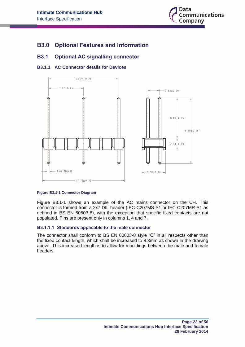
Figure B3.1-1 Connector Diagram
Figure B3.1-1 shows an example of the AC mains connector on the CH. This connector is formed from a 2x7 DIL header (IEC-C207MS-S1 or IEC-C207MR-S1 as defined in BS EN 60603-8), with the exception that specific fixed contacts are not populated. Pins are present only in columns 1, 4 and 7.
B3.1.1.1 Standards applicable to the male connector
The connector shall conform to BS EN 60603-8 style “C” in all respects other than the fixed contact length, which shall be increased to 8.8mm as shown in the drawing above. This increased length is to allow for mouldings between the male and female headers.
Intimate Communications Hub
Interface Specification
Page 24 of 56 Intimate Communications Hub Interface Specification
28 February 2014
B3.1.2 AC Connector details for Hosts
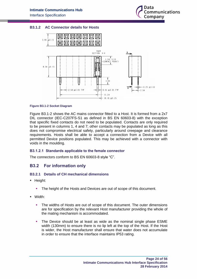
Figure B3.1-2 Socket Diagram
Figure B3.1-2 shows the AC mains connector fitted to a Host. It is formed from a 2x7 DIL connector (IEC-C207FS-S1 as defined in BS EN 60603-8) with the exception that specific fixed contacts do not need to be populated. Contacts are only required to be present in columns 1, 4 and 7; other contacts may be populated as long as this does not compromise electrical safety, particularly around creepage and clearance requirements. Hosts shall be able to accept a connection from a Device with all permitted Device positions populated. This may be achieved with a connector with voids in the moulding.
B3.1.2.1 Standards applicable to the female connector
The connectors conform to BS EN 60603-8 style “C”.
B3.2 For information only
B3.2.1 Details of CH mechanical dimensions
Height:
The height of the Hosts and Devices are out of scope of this document.
Width:
The widths of Hosts are out of scope of this document. The outer dimensions are for specification by the relevant Host manufacturer providing the whole of the mating mechanism is accommodated.
The Device should be at least as wide as the nominal single phase ESME width (130mm) to ensure there is no lip left at the top of the Host. If the Host is wider, the Host manufacturer shall ensure that water does not accumulate in order to ensure that the interface maintains IP53 rating.

Intimate Communications Hub
Interface Specification
Page 25 of 56 Intimate Communications Hub Interface Specification
28 February 2014
Depth of the CH towards the back face:
To avoid the CH fouling on the wall to which a minimum depth ESME has been mounted, the theoretical maximum depth of the CH (from the datum plane) is 47.3 mm.
The Host manufacturer shall ensure that water does not collect behind the interface if the CH does not extend the full 47.3mm behind the datum, or if the Host places the datum more than 47.3mm in front of the back face.
Depth of CH towards the front of the Host:
The depths of Hosts and Devices are out of scope of this document. The outer dimensions are for specification by the relevant manufacturer providing the whole of the mating mechanism is accommodated.
The Communications Hub design should place the front face at least 17.7 mm from the datum plane.
The Host manufacturer shall ensure that water does not collect in front of the interface if the Host places the datum more than 17.7mm behind the front face.
Figure B3.2-1 shows some possible CH shapes – these are examples and should not be taken as guides.
Figure B3.2-1 Possible shapes for the CH – for guidance only
Intimate Communications Hub
Interface Specification
Page 26 of 56 Intimate Communications Hub Interface Specification
28 February 2014
DC Power Part C
Requirements for Provision of DC Power C1.0
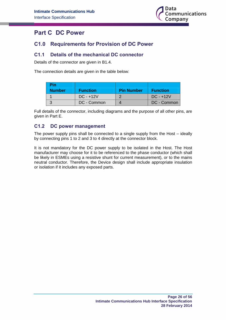
C1.1 Details of the mechanical DC connector
Details of the connector are given in B1.4.
The connection details are given in the table below:
Full details of the connector, including diagrams and the purpose of all other pins, are given in Part E.
C1.2 DC power management
The power supply pins shall be connected to a single supply from the Host – ideally by connecting pins 1 to 2 and 3 to 4 directly at the connector block.
It is not mandatory for the DC power supply to be isolated in the Host. The Host manufacturer may choose for it to be referenced to the phase conductor (which shall be likely in ESMEs using a resistive shunt for current measurement), or to the mains neutral conductor. Therefore, the Device design shall include appropriate insulation or isolation if it includes any exposed parts.
Pin
Number Function Pin Number Function
1 DC - +12V 2 DC - +12V
3 DC - Common 4 DC - Common
Intimate Communications Hub
Interface Specification
Page 27 of 56 Intimate Communications Hub Interface Specification
28 February 2014
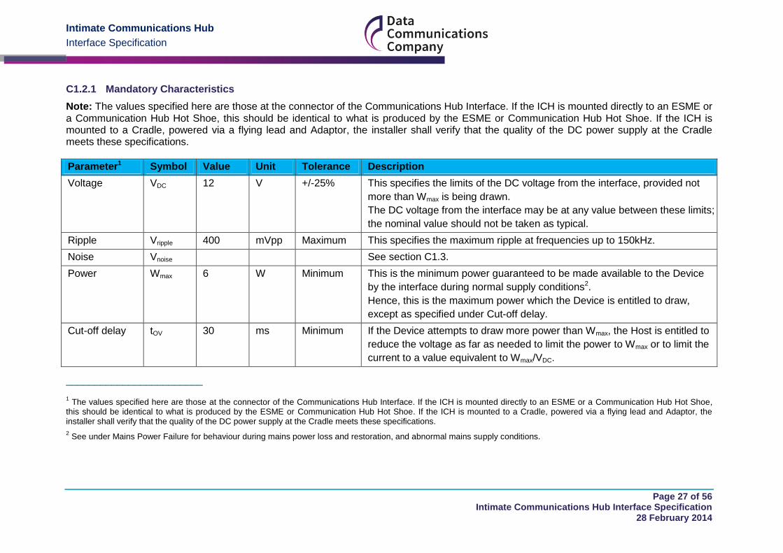
C1.2.1 Mandatory Characteristics
Note: The values specified here are those at the connector of the Communications Hub Interface. If the ICH is mounted directly to an ESME or a Communication Hub Hot Shoe, this should be identical to what is produced by the ESME or Communication Hub Hot Shoe. If the ICH is mounted to a Cradle, powered via a flying lead and Adaptor, the installer shall verify that the quality of the DC power supply at the Cradle meets these specifications.
Parameter1 Symbol Value Unit Tolerance Description
Voltage VDC 12 V +/-25% This specifies the limits of the DC voltage from the interface, provided not
more than Wmax is being drawn.
The DC voltage from the interface may be at any value between these limits;
the nominal value should not be taken as typical.
Ripple Vripple 400 mVpp Maximum This specifies the maximum ripple at frequencies up to 150kHz.
Noise Vnoise See section C1.3.
Power Wmax 6 W Minimum This is the minimum power guaranteed to be made available to the Device
by the interface during normal supply conditions2.
Hence, this is the maximum power which the Device is entitled to draw,
except as specified under Cut-off delay.
Cut-off delay tOV 30 ms Minimum If the Device attempts to draw more power than Wmax, the Host is entitled to
reduce the voltage as far as needed to limit the power to Wmax or to limit the
current to a value equivalent to Wmax/VDC.
________________________
1 The values specified here are those at the connector of the Communications Hub Interface. If the ICH is mounted directly to an ESME or a Communication Hub Hot Shoe,
this should be identical to what is produced by the ESME or Communication Hub Hot Shoe. If the ICH is mounted to a Cradle, powered via a flying lead and Adaptor, the installer shall verify that the quality of the DC power supply at the Cradle meets these specifications.
2 See under Mains Power Failure for behaviour during mains power loss and restoration, and abnormal mains supply conditions.

Intimate Communications Hub
Interface Specification
Page 28 of 56 Intimate Communications Hub Interface Specification
28 February 2014
Parameter1 Symbol Value Unit Tolerance Description
For the avoidance of doubt, the quantity for VDC in the above function is the
nominal value defined under VDC earlier in this table.
As defined above, the limiter characteristic in the Host shall approximate to
a power-limit function or to a current-limit function, or to a blend of the two
characteristics.
If the load condition causing the Host to enter this power-limit state persists
for longer than time tOV, the Host is entitled to cut off the DC voltage supply.
The purpose of the cut-off delay is to allow for the presence of uncharged
capacitance at the supply input to the Device under “hot swap” conditions,
up to 220uF (nominal). If ultra-caps or similar high-capacitance energy
storage is used in the Device in support of “last gasp” or similar features, the
charging of these capacitances shall be managed by the Device.
Note: Once the limiting function of the Host has been triggered, in order to
guarantee exit of the DC Voltage supply from the limiting state, and without
entering cut-off, the Device would need to reduce both its load current below
Wmax/VDC and its input power below Wmax. This process can be automatic,
without elaborate design precautions in the Device. The input capacitance of
the Device shall charge to the target VDC value, and the Device shall then
start up. It is recommended that the Device does not start up until the DC
voltage supply at the input to the Device has stabilised within the range
specified under VDC.
Note: The Host is not obliged to limit the power drawn to Wmax, or to cut off
the DC Voltage supply at time tOV under this load condition, except as
specified under Guaranteed cut-off.
Warning: Cut-off of the DC voltage supply is regarded as a fault condition in
the Device, and designers of Devices should not attempt to use the
assumed cut-off characteristic of the Host as part of a power management

Intimate Communications Hub
Interface Specification
Page 29 of 56 Intimate Communications Hub Interface Specification
28 February 2014
Parameter1 Symbol Value Unit Tolerance Description
strategy. The cut-off characteristic of the DC voltage may vary considerably
from one model of Host to another within the bounds of this specification.
The Host may log instances of cut-off and this log may be used to determine
a need to swap out the Device.
Re-try timer tRT 10-40 x
tOV min
ms If the Host cuts off the DC voltage supply as described under cut-off delay or
guaranteed cut-off, the Host shall re-connect the supply after tRT.
If the load which caused cut-off is still present, the Host shall cycle through
the cut-off delay process or guaranteed cut-off process as described under
the respective headings.
Guaranteed
cut-off level
Wcutoff 2 x Wmax W Maximum If the Device draws more than Wcutoff, the Host shall cut off the DC Voltage
supply within time tGC.
Note that the Host is not obliged to supply more than Wmax, but if it does, it is
obliged to not supply more than Wcutoff for longer than tGC.
Guaranteed
cut-off timer
tGC 45 ms Maximum See under Guaranteed cut-off level.
Cut-off leakage
current
Ico 1 mA Maximum In the cut off state, the leakage current from the Host into the load of the
Device shall not exceed Ico.
The purpose of specifying a maximum value for this parameter is to enable
the designers of Devices to ensure that the Device shall be fully reset by the
cut-off action of the Host.
Mains supply
failure: Hold-up
time
tHU 0 ms Minimum The DC voltage supply is not intended to provide a “hold-up” function to the
Device.
The characteristics defined variously above for the DC voltage supply apply
while the mains supply to the Host is between the minimum and maximum
operating voltages specified for the Host to support the DC Voltage supply
Intimate Communications Hub
Interface Specification
Page 30 of 56 Intimate Communications Hub Interface Specification
28 February 2014
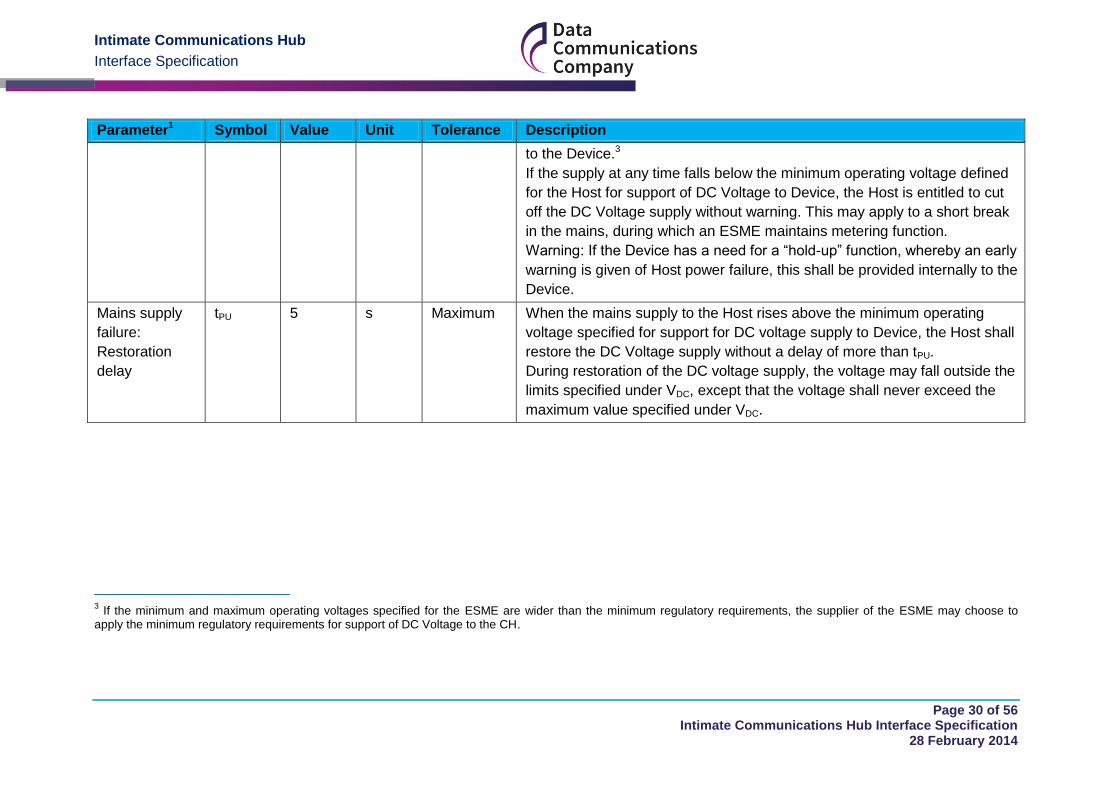
Parameter1 Symbol Value Unit Tolerance Description
to the Device.3
If the supply at any time falls below the minimum operating voltage defined
for the Host for support of DC Voltage to Device, the Host is entitled to cut
off the DC Voltage supply without warning. This may apply to a short break
in the mains, during which an ESME maintains metering function.
Warning: If the Device has a need for a “hold-up” function, whereby an early
warning is given of Host power failure, this shall be provided internally to the
Device.
Mains supply
failure:
Restoration
delay
tPU 5 s Maximum When the mains supply to the Host rises above the minimum operating
voltage specified for support for DC voltage supply to Device, the Host shall
restore the DC Voltage supply without a delay of more than tPU.
During restoration of the DC voltage supply, the voltage may fall outside the
limits specified under VDC, except that the voltage shall never exceed the
maximum value specified under VDC.
________________________ 3 If the minimum and maximum operating voltages specified for the ESME are wider than the minimum regulatory requirements, the supplier of the ESME may choose to
apply the minimum regulatory requirements for support of DC Voltage to the CH.
Intimate Communications Hub
Interface Specification
Page 31 of 56 Intimate Communications Hub Interface Specification
28 February 2014
C1.3 EMC requirements on DC power supply
The DC power supply of the Host is intended for use with CHs that have the immunity to RF common mode noise on their DC power ports as specified in the following sub-section.
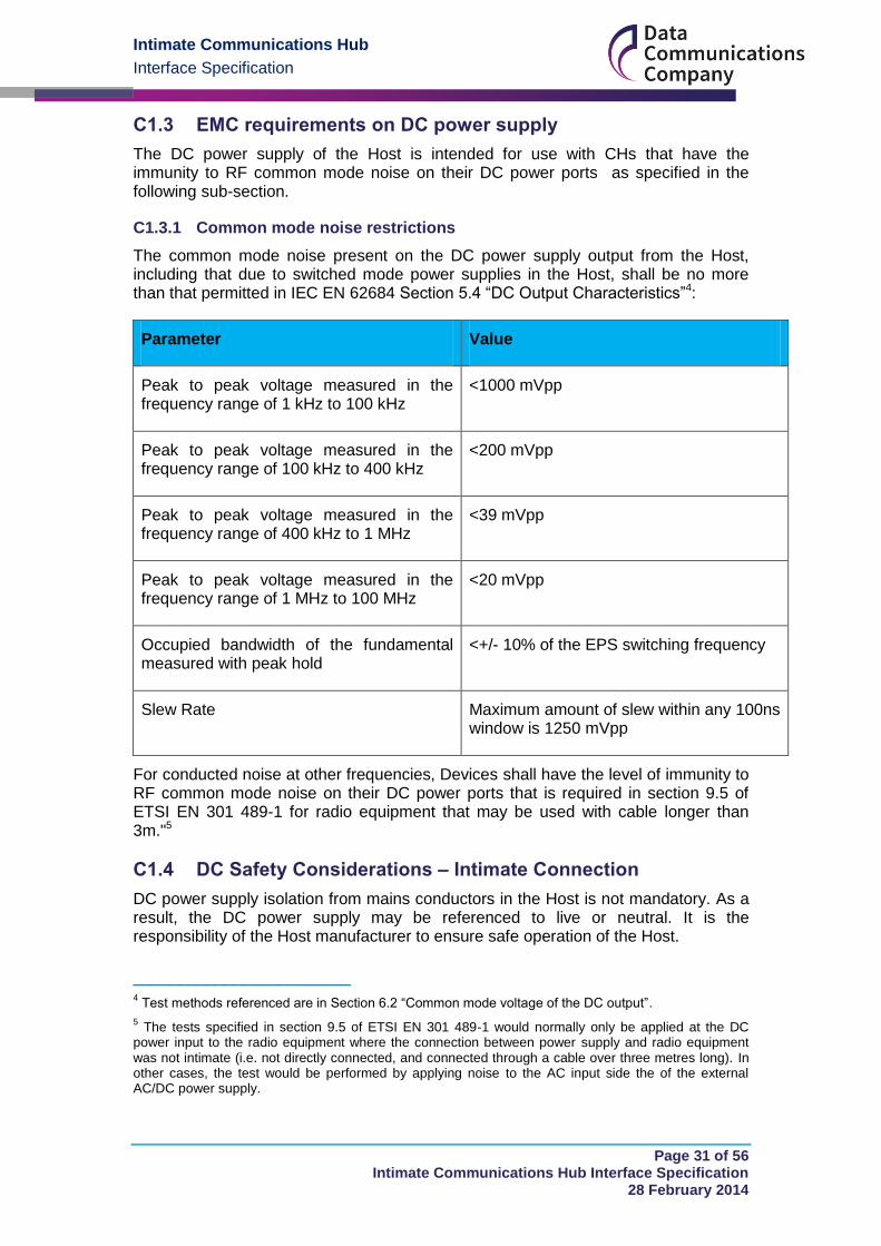
C1.3.1 Common mode noise restrictions
The common mode noise present on the DC power supply output from the Host, including that due to switched mode power supplies in the Host, shall be no more than that permitted in IEC EN 62684 Section 5.4 “DC Output Characteristics”4:
Parameter Value
Peak to peak voltage measured in the frequency range of 1 kHz to 100 kHz
<1000 mVpp
Peak to peak voltage measured in the frequency range of 100 kHz to 400 kHz
<200 mVpp
Peak to peak voltage measured in the frequency range of 400 kHz to 1 MHz
<39 mVpp
Peak to peak voltage measured in the frequency range of 1 MHz to 100 MHz
<20 mVpp
Occupied bandwidth of the fundamental measured with peak hold
<+/- 10% of the EPS switching frequency
Slew Rate Maximum amount of slew within any 100ns window is 1250 mVpp
For conducted noise at other frequencies, Devices shall have the level of immunity to RF common mode noise on their DC power ports that is required in section 9.5 of ETSI EN 301 489-1 for radio equipment that may be used with cable longer than 3m."5
C1.4 DC Safety Considerations – Intimate Connection
DC power supply isolation from mains conductors in the Host is not mandatory. As a result, the DC power supply may be referenced to live or neutral. It is the responsibility of the Host manufacturer to ensure safe operation of the Host.
________________________ 4 Test methods referenced are in Section 6.2 “Common mode voltage of the DC output”.
5 The tests specified in section 9.5 of ETSI EN 301 489-1 would normally only be applied at the DC
power input to the radio equipment where the connection between power supply and radio equipment was not intimate (i.e. not directly connected, and connected through a cable over three metres long). In other cases, the test would be performed by applying noise to the AC input side the of the external AC/DC power supply.
Intimate Communications Hub
Interface Specification
Page 32 of 56 Intimate Communications Hub Interface Specification
28 February 2014
The Device manufacturer needs to ensure appropriate protection in the Device against fault conditions; the Host shall remain safe if a fault occurs in the flying lead or CH that results in a low impedance connection to ground or mains neutral.
For an Installation to be considered safe, as well as conforming to the relevant safety standards, when tested for the effects of short circuit and overload currents at least the following statements should be true:
Any material or hot gas that is ejected by the Host and Device assembly shall not cause fire.
Insulation between mains circuits and accessible conducting parts, including low-voltage auxiliary circuits shall remain intact. The ESME/Host shall pass the insulation tests given in BS EN 50470-1:2006, Section 7.3.3 and 7.3.4 after a fault event.
Any fuse incorporated in the Host is not intended to provide protection against electrical shock and shall not be represented as such. The risk remains equivalent to accessing the main ESME terminals.
The design of a Device shall not be based on any assumption that the Host contains additional impedances which would limit the prospective short circuit current values at the mains input of the Device. Hosts compliant with this ICHI Specification are not required to include short-circuit current limiting impedances between their main terminals and the live AC connections, including phase referenced DC connections made available in the interface.
The specification for the mechanical design of the interface ensures that the contacts become inaccessible before the male and female parts make electrical contact.
C1.5 DC Safety Consideration – External Metal – Device
As the DC power supply from the Host may not be isolated from the AC mains, any external metal on the Device (including a connector for an external antenna) shall be isolated from the DC power supply within the Device.
Specific requirements for the provision of DC power C2.0
C2.1 Specific requirements for Communications Hubs
A Communications Hub shall comply with the following tests, aligned with the comparable tests required of ESMEs:
C2.1.1 Insulation
The Device shall retain adequate dielectric qualities under normal conditions of use, taking into account the effects of the climatic environment and different voltages to which it is subjected under normal conditions of use.
When coupled with a separate Host which has already passed the impulse voltage test and the AC voltage test as specified in BS EN 50470-1:2006, Section 7.3.1 to 7.3.3, the combination shall remain compliant with the tests below. For the avoidance of doubt, not every combination of CH and Host needs to be tested, however each CH and Host manufacturer must be able to demonstrate compliance.
Intimate Communications Hub
Interface Specification
Page 33 of 56 Intimate Communications Hub Interface Specification
28 February 2014
C2.1.1.1 General test conditions
The tests shall be carried out only on a complete Installation with all covers fitted (except when indicated hereinafter) and terminal cover, the terminal screws being screwed down to the maximum applicable conductor fitted in the terminals.
Test procedure in accordance with IEC 60060-1.
The impulse voltage tests shall be carried out first and the AC voltage tests afterwards.
During type tests, the dielectric strength tests are considered to be valid only for the terminal arrangement of the ESME which has undergone the tests. When the terminal arrangements differ, all the dielectric strength tests shall be carried out for each arrangement.
For the purpose of these tests, the term ‘earth’ is a conductive foil wrapped around the Installation touching all accessible conductive parts and connected to the flat conducting surface on which the ESME base is placed. Where the terminal cover makes it possible, the conductive foil shall approach the terminals and the holes for the conductors within a distance of not more than 2 cm.
During the impulse and the AC voltage tests, the circuits which are not under test are connected to the earth as indicated hereinafter.
After these tests, there shall be no mechanical damage to the Host or Device.
These tests shall be made in normal conditions of use. During the test, the quality of the insulation shall not be impaired by dust or abnormal humidity.
Unless otherwise specified, the normal conditions for insulation tests are:
ambient temperature: 15 °C to 25 °C;
relative humidity: 45 % to 75 %;
atmospheric pressure: 86 kPa to 106 kPa.
If for any reason the insulation tests have to be repeated, then they may be performed on a new specimen.
C2.1.1.2 Impulse Voltage Test
The test shall be carried out under the following conditions:
impulse waveform: 1.2/50 impulse specified in IEC 60060-1;
voltage rise time: ±30 %;
voltage fall time: ±20 %;
source impedance: 500 ± 50 ;
source energy: 0.5 J ± 0.05 J;
test voltage: 4000V;
Intimate Communications Hub
Interface Specification
Page 34 of 56 Intimate Communications Hub Interface Specification
28 February 2014
test voltage tolerance: +0 − 10 %.
For each test, the impulse voltage is applied ten times with one polarity and then repeated with the other polarity. The minimum time between the impulses shall be 3 seconds.
C2.2 Specific requirements for single phase ESMEs
The DC power shall be derived from the unmetered side of the ESME before any measurement element. The DC power supplied by the ESME shall be the same as specified in C1.2.
C2.3 Specific requirements for single phase, twin element ESMEs
The DC power shall be derived from the unmetered side of the main circuit in the ESME before any measurement element. The DC power supplied by the ESME shall be the same as specified in C1.2.
C2.4 Specific requirements for polyphase ESMEs
The DC power shall be derived from the unmetered side of the ESME before any of the measurement elements. The DC power supplied by the ESME shall be the same as specified in C1.2.
The DC power shall continue to be supplied from the ESME in case of any loss of phase as per BS EN 50470-3 – Table 9 Note (a).
C2.5 Specific requirements for Communication Hub Hot Shoes
The DC power supplied by the Communication Hub Hot Shoe shall be the same as specified in C1.2.
C2.6 Specific requirements for Adaptors and Cradles
The DC interface of the ESME may be used to provide DC power for a remote CH via an Adaptor, flying lead and Cradle. The protection of the flying lead and the CH shall be the responsibility of the manufacturer of the Adaptor, flying lead and Cradle.
The DC power supplied by the Cradle shall be the same as specified in C1.2. It shall be up to the manufacturer to ensure compatible ESMEs and / or CH provide adequate margin on DC voltage to compensate for any voltage drop across the Adaptor, flying lead and Cradle.
The connection methodology for the flying lead shall not compromise any of the electrical or safety considerations of the ESME and CH interfaces prescribed under this Part C.
DC power supply isolation from mains conductors is not mandatory. As a result, the DC power supply may be referenced to live or neutral. It is the responsibility of the Adaptor, flying lead and Cradle manufacturer to ensure safe operation of the Installation.
The Adaptor shall provide overcurrent and fault current protection for all the conductors in the cable, including the “DC-Common” and “DC - +12V” lines. This protection shall address the case of damage to the cable, or where an attempt was
Intimate Communications Hub
Interface Specification
Page 35 of 56 Intimate Communications Hub Interface Specification
28 February 2014
made to extract un-metered energy from the end of the flying lead remote from the ESME.
The Adaptor shall be fitted with appropriate fuse(s).
The insulation system provided in the cable of the flying lead shall provide adequate functional and safety insulation commensurate with the conductors of the flying lead being connected to the mains network very close to the point of entry of the mains supply into the building (before the consumer distribution unit). The strength of the insulation shall be adequate for the expected phase to ground over-voltages at this point. Installation of the flying lead shall conform to BS7671:2008 and BS7540.
There must be no expectation that the ESME shall provide any attenuation or clamping of phase to ground over-voltages.
A Cradle or Communication Hub Hot Shoe shall comply with the EMC requirements set out in BS EN 61204-3:2001 and all other tests specified in C2.1.1.2.
Other DC Power Considerations (For information only) C3.0
C3.1 Considerations for fusing Lsupply, Lload, and DC connections
Any fuse provided in the Host or Device shall coordinate with the service cut-out fuse and shall create an open circuit (“blow”) first under all circumstances. This is not seen to be an issue where the cut-out fuse is rated at 60A, 80A or 100A, but would need to be given careful consideration if very low value (5A, 10A) cut-out fuses were ever used.
The rating of the fuse shall be able to cope with 10kA maximum prospective fault currents.
The ESME cannot be assumed to include any fusing or other protection on its outputs, but individual ESME manufacturers may design-in additional levels of protection as best practice or as acceptable to procuring energy suppliers.
This specification advises CH suppliers that the DC power supply output of the ICHI from the Host may not necessarily be isolated from the mains supply in all circumstances. The DC-Common connectors may be directly connected, through low impedance circuits, to the Lsupply terminal of the Host. Alternatively, it may be connected to the Neutral of the mains, or it may be floating.
If the DC-common is connected to Lsupply, then it follows that there shall be galvanic connections between the DC - +12V connections and Lsupply.
The specification for the DC power supply output of the ESME (section C1.2) includes the requirement for protection against overcurrent and short circuits between the “DC-Common” and “DC - +12V” connector pins. That specification does not address the risks of fault currents flowing from the “DC-Common” and or “DC - +12V” connections and mains live or protective earth conductors.
Suppliers of CH shall ensure that the Devices provide adequate protection against contact with the potentially live internal circuits. This shall be true even if the ICH only connects to the DC power supply output from the ESME.

Intimate Communications Hub
Interface Specification
Page 36 of 56 Intimate Communications Hub Interface Specification
28 February 2014
Where the CH is to be mounted remotely from the ESME and connected by a flying lead linking an ESME-mounted Adaptor and a Cradle, the Adaptor shall provide overcurrent and fault current protection for all the conductors in the flying lead, including the “DC-Common” and “DC - +12V” lines. This protection shall address the case of damage to the flying lead, or where an attempt was made to extract un-metered energy from the end of the flying lead remote from the ESME.
C3.2 Power Supply References
The DC power supply may be referenced to live or neutral dependent on the Host design. To be interoperable, an ICH shall function safely and correctly regardless of whether it is installed onto a Host with live reference or neutral referenced DC power supply output.
Intimate Communications Hub
Interface Specification
Page 37 of 56 Intimate Communications Hub Interface Specification
28 February 2014
Optional AC Signalling Provision Part D
Introduction D1.0
D1.1 Purpose
Where provided, the purpose of the AC signalling connections is not to provide AC power for a Communications Hub, as it is required that the Communications Hub will derive power from the mandatory DC connector. If AC signals are present on an interface variant, the CH shall not use them to derive its power supply.
Connections to the AC supply could be used to couple PLC signals onto the incoming and/or outgoing mains connectors.
The incoming connection to Lsupply could be used for messages on a wired PLC WAN at all times, and on a wired PLC HAN when the premise’s load relay is connected (closed).
The outgoing connection Lload could be used for messages on a wired PLC HAN when the premise’s load relay is disconnected (open). This could be used, for example with (battery powered) PPMID devices to add credit to a disconnected prepayment ESME.
D1.2 Conditions for use of AC signalling
The provision of the connector for AC signalling is not a mandatory part of ICHIS.
A Host which does provide the AC Signalling connector shall provide one of the following connection options where the pin definitions are provided in D2.1:
Lsupply and N – Nsupply and Lload
Lsupply and N – Nsupply only
N – Nsupply and Lload only
The signals provided by the Host shall be clearly marked near the connector, and clearly identifiable.
The Host shall be marked with appropriate symbols indicating the supported signals and the type and limits of fusing which protects the connector, for example:
Figure D1.2-1 Examples of fusing symbols
Intimate Communications Hub
Interface Specification
Page 38 of 56 Intimate Communications Hub Interface Specification
28 February 2014
Requirements for the provision of AC Signalling D2.0
D2.1 Connector Details
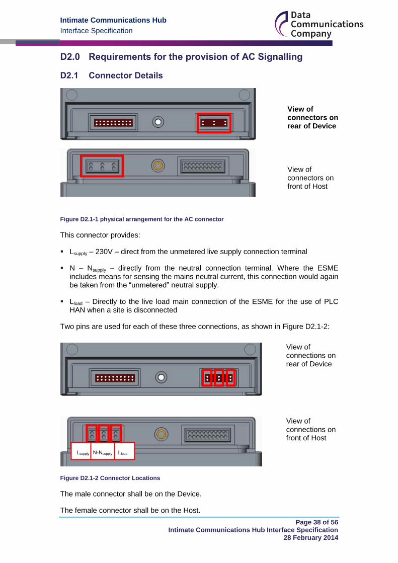
View of connectors on rear of Device
View of connectors on front of Host
Figure D2.1-1 physical arrangement for the AC connector
This connector provides:
Lsupply – 230V – direct from the unmetered live supply connection terminal
N – Nsupply – directly from the neutral connection terminal. Where the ESME includes means for sensing the mains neutral current, this connection would again be taken from the “unmetered” neutral supply.
Lload – Directly to the live load main connection of the ESME for the use of PLC HAN when a site is disconnected
Two pins are used for each of these three connections, as shown in Figure D2.1-2:
View of connections on rear of Device
View of connections on front of Host
Figure D2.1-2 Connector Locations
The male connector shall be on the Device.
The female connector shall be on the Host.
Lload Lsupply N-Nsupply
Intimate Communications Hub
Interface Specification
Page 39 of 56 Intimate Communications Hub Interface Specification
28 February 2014
The spacing between pins complies with appropriate creepage and clearance standards. Refer to D2.2 below on appropriate safety standards.
Lload allows for a CH incorporating PLC HAN without the need to bypass the contactor when the switch is open.
D2.2 Safety Requirements
For an Installation to be considered safe, as well as conforming to the relevant safety standards, when tested for the effects of short circuit and overload currents at least the following statements should be true:
Any material or hot gas that is ejected by the Host and Device assembly shall not cause fire.
Insulation between mains circuits and accessible conducting parts, including low-voltage auxiliary circuits shall remain intact. The ESME/Host shall pass the insulation tests given in BS EN 50470-1:2006, Section 7.3.3 and 7.3.4 after a fault event.
Note: Any fuse incorporated in the ESME is not intended to provide protection against electrical shock. The risk remains equivalent to accessing the main ESME terminals.
The manufacturer of a Host may choose to fit a fuse(s) as part of the fail-safe implementation to any or all of the live AC connections to the ICH. In such cases, the fuse type and rating shall be marked near the connection, and the fusing mechanism shall not impede any existing narrowband or broadband PLC technologies. For example:
Figure D2.2-1 Examples of fusing symbols
The design of an ICH shall not be based on any assumption that the ESME contains additional impedances which would limit the prospective short circuit current values at the mains input of the CH. ESMEs compliant with this ICHIS are not required to include short-circuit current limiting impedances between their main terminals and the live AC connections made available in the interface.
The specification for the mechanical design of the Host and Device interface ensures that the contacts become “inaccessible” before the male and female parts make electrical contact.
If a flying lead is used between an Adaptor and Cradle, the safety requirements in section C3.0 shall be respected.
D2.3 PLC Coupling requirements
If a current of greater than 0.25A is drawn from this supply, there may be a permanent failure of the AC connection inside the Host. In this event, the Host shall remain safe. Where a downstream fuse is provided in the Device, the rating of that fuse shall be coordinated with the rating of the output of the ICHI. A typical rating of the fuse in the CH would be less than 70% of the ICHI rating i.e. <70% of 0.25A.
Intimate Communications Hub
Interface Specification
Page 40 of 56 Intimate Communications Hub Interface Specification
28 February 2014
The AC signalling pins may pass through some protective circuitry in the Host. In this case, there shall be no attenuation of signals in the:
Narrowband PLC frequency range: 9kHz – 500kHz
Broadband over PowerLine frequency range: 1.6MHz – 80MHz
Specific requirements for AC Signalling Connections D3.0
D3.1 Specific requirements for Communications Hubs
The AC connection pins are not mandatory on a Communications Hub. However, if fitted they shall comply with all of the requirements in Part D and Part B3.1.1
D3.2 Specific requirements for Blanking Plates
A Blanking Plate shall not provide the AC Signalling pins.
D3.3 Specific requirements for single phase ESMEs
The AC connection socket is not mandatory on a single phase ESME. However, if fitted it shall comply with all of the requirements in Part D and Part B3.1.2. Notably, it shall accept pins of a corresponding Device physically fitting onto the ESME.
D3.4 Specific requirements for twin element ESMEs
The AC connection socket is not mandatory on a twin element ESME. However, if fitted it shall comply with all of the requirements in Part D and Part B3.1.2. Notably, it shall accept pins of a corresponding Device physically fitting onto the ESME.
If fitted, the Lload connection shall be connected to the main output of the ESME, to the primary disconnect switch.
D3.5 Specific requirements for polyphase ESMEs
The AC connection socket is not mandatory on a polyphase ESME. However, if fitted it shall comply with all of the requirements in Part D and Part B3.1.2. Notably, it shall accept pins of a corresponding Device physically fitting onto the ESME.
If fitted, the Lsupply connection and Lload shall be connected to L1 of the ESME.
D3.6 Specific requirements for Communication Hub Hot Shoes
The AC connection socket is not mandatory on a Communication Hub Hot Shoe. However, if fitted it shall comply with all of the requirements in Part D and Part B3.1.2. Notably, it shall accept pins of a corresponding Device physically fitting onto the Communication Hub Hot Shoe.
A Communication Hub Hot Shoe may provide only the corresponding connections for Lsupply and N-Nsupply, in which case it would not provide PLC HAN connections (when the ESME is in a disconnect state).
D3.7 Specific requirements for Cradles
The AC connection socket is not mandatory on a Cradle. However, if fitted it shall comply with all of the requirements in Part D and Part B3.1.2. Notably, it shall not impede any pins of a corresponding CH physically fitting onto the ESME.
Intimate Communications Hub
Interface Specification
Page 41 of 56 Intimate Communications Hub Interface Specification
28 February 2014
A Cradle may provide any of the combinations of connections referenced in D1.2.
D3.8 Specific requirements for Adaptors
The AC Signalling pins for the ICH in the ESME may be used to provide AC mains for a Cradle via an Adaptor with a flying lead. The protection of the flying lead and the Cradle shall be the responsibility of the manufacturer of the Adaptor. The Adaptor shall be fitted with an appropriate fuse.
The insulation system provided in the cable of the flying lead shall provide adequate functional and safety insulation commensurate with the conductors of the cable being connected to the mains network very close to the point of entry of the mains supply into the building (before the consumer distribution unit). The strength of the insulation will be adequate for the expected phase to neutral over-voltages at this point, and for the expected phase to ground over-voltages. There must be no expectation that the ESME will provide any attenuation or clamping of phase to neutral over-voltages. The ESME will not have any electrical connection to ground, so again it is not able to provide any attenuation or clamping of phase to ground over-voltages. It is the responsibility of the Adaptor, flying lead and Cradle manufacturer to ensure safe operation of the Installation.
Shielding of the flying lead should also be considered in order to maintain the EMC requirements of the power supply.
The conductors provided in the flying lead cable shall have adequate cross section to prevent excessive voltage drops or heating when the cable is carrying the rated 50Hz current drawn by the CH. The total impedance of the assembly – including that of the in-line protective devices (such as fuses), the phase conductor, and the neutral conductor – shall not exceed 10 ohms when measured at 23°C and 50Hz.

Intimate Communications Hub
Interface Specification
Page 42 of 56 Intimate Communications Hub Interface Specification
28 February 2014
Digital Signalling Pins Part E
Introduction E1.0
E1.1 Purpose
There are 16 digital signalling pins on the same connector as the mandatory DC power supply pins.
These hardwired pins are (or can be) used for interaction between the Host and the Device.
View of digital
signalling pins on
rear of Device
View of digital
signalling pins on
front of Host
Figure E1.1-1 Digital Signalling Pins
E1.2 Pin Positioning
1
12V
3
Com-
mon
5
CH_
PR
7
TX_
MT
9
AC_
LO
11
CSP_
B
13
RMM_
B
15
RMM_
D
17
RMM_
F
19
CSP_
E
2
12V
4
Com-
mon
6
MT_
PR
8
RX_
MT
10
CSP_
A
12
CSP_
C
14
RMM_
C
16
RMM_
E
18
CSP_
D
20
CSF_
F
20
19
2
1
19
20 2
1
Intimate Communications Hub
Interface Specification
Page 43 of 56 Intimate Communications Hub Interface Specification
28 February 2014
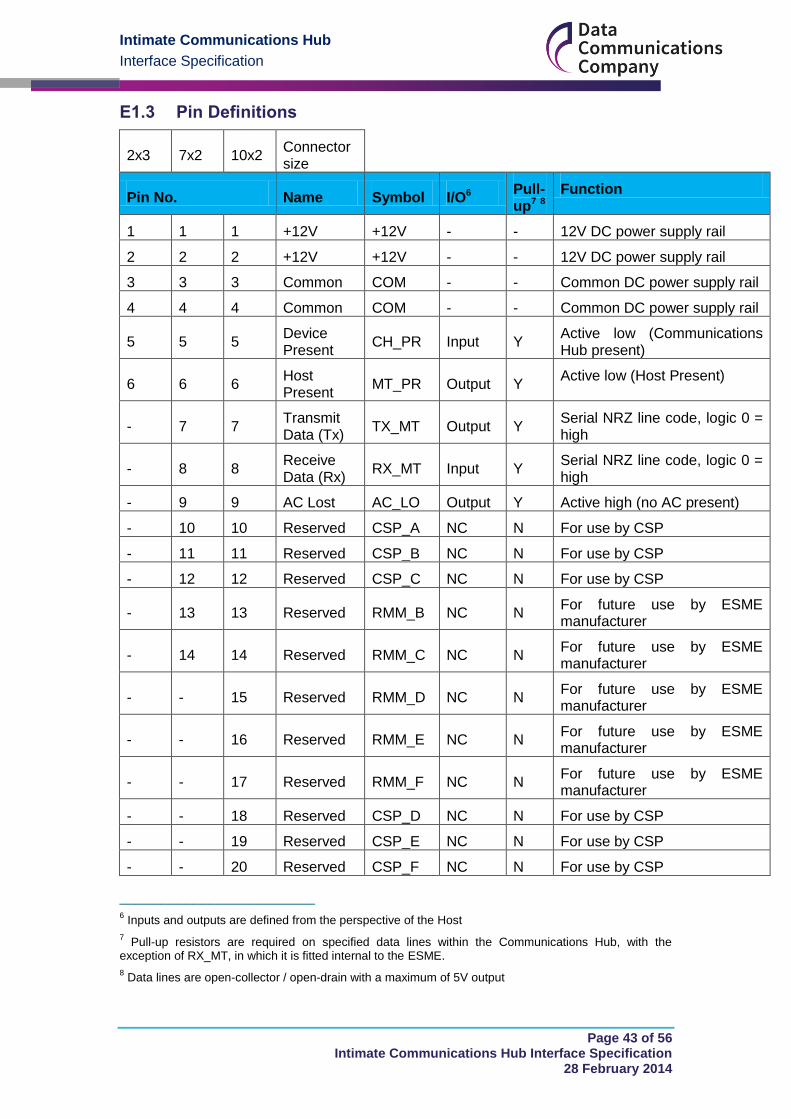
E1.3 Pin Definitions
2x3 7x2 10x2 Connector size
Pin No. Name Symbol I/O6 Pull-up7 8
Function
1 1 1 +12V +12V - - 12V DC power supply rail
2 2 2 +12V +12V - - 12V DC power supply rail
3 3 3 Common COM - - Common DC power supply rail
4 4 4 Common COM - - Common DC power supply rail
5 5 5 Device Present
CH_PR Input Y Active low (Communications Hub present)
6 6 6 Host Present
MT_PR Output Y Active low (Host Present)
- 7 7 Transmit Data (Tx)
TX_MT Output Y Serial NRZ line code, logic 0 = high
- 8 8 Receive Data (Rx)
RX_MT Input Y Serial NRZ line code, logic 0 = high
- 9 9 AC Lost AC_LO Output Y Active high (no AC present)
- 10 10 Reserved CSP_A NC N For use by CSP
- 11 11 Reserved CSP_B NC N For use by CSP
- 12 12 Reserved CSP_C NC N For use by CSP
- 13 13 Reserved RMM_B NC N For future use by ESME manufacturer
- 14 14 Reserved RMM_C NC N For future use by ESME manufacturer
- - 15 Reserved RMM_D NC N For future use by ESME manufacturer
- - 16 Reserved RMM_E NC N For future use by ESME manufacturer
- - 17 Reserved RMM_F NC N For future use by ESME manufacturer
- - 18 Reserved CSP_D NC N For use by CSP
- - 19 Reserved CSP_E NC N For use by CSP
- - 20 Reserved CSP_F NC N For use by CSP
________________________ 6 Inputs and outputs are defined from the perspective of the Host
7 Pull-up resistors are required on specified data lines within the Communications Hub, with the
exception of RX_MT, in which it is fitted internal to the ESME.
8 Data lines are open-collector / open-drain with a maximum of 5V output

Intimate Communications Hub
Interface Specification
Page 44 of 56 Intimate Communications Hub Interface Specification
28 February 2014
E1.3.1 MT_PR
MT_PR is used by a Communications Hub to detect the presence (or lack thereof) of the female socket of the ICHI provided by a Host. A Host shall provide a low impedance connection of no more than 10Ω between MT_PR and COM.
E1.3.2 CH_PR
CH_PR is used by an ESME to detect the presence (or lack thereof) of the male connector of the ICHI provided by a Device. A Device shall provide a low impedance connection of no more than 10Ω between CH_PR and COM.
E1.3.3 TX_MT / RX_MT
TX_MT and RX_MT are UART data transmission connections. They are not used for this iteration of the ICHIS, but are defined as data connections for future use.
E1.3.4 AC_LO, RMM_B-F
AC_LO and RMM_B, C, D, E, F will not be used for UK application in this iteration of ICHIS. These pins are reserved for ESME manufacturers’ use in foreign markets, and/or potential use in future iterations of ICHIS for use in Great Britain.
E1.3.5 CSP_A-F
CSP_A, B, C, D, E, F are reserved for use by the CSPs. Hosts shall not connect to these pins (though shall cater for their physical presence).
General requirements for Digital Signalling Pins E2.0
E2.1 Performance Requirements for Open-collector Outputs
Symbol Connector Logical Low Voltage, Rpull-up > 1.0 kΩ
Logical High Voltage, Rpull-up < 100 kΩ
TX_MT ESME < 1.0 V > (Vlogic - 0.5 V)
AC_LO ESME < 1.0 V > (Vlogic - 0.5 V)
RX_MT CH < 1.0 V > (Vlogic - 0.5 V)
Notes:
1. Applicable over declared operating temperature range.
2. For DC rails of 3.0 V < Vlogic < 5.0 V.
3. Current drawn from each pin may not exceed 4mA.
E2.2 EMC Requirements on Data Lines
ESME manufacturers may assume that the CH generates conducted emissions onto the data lines within the limits given in ETSI EN 301 489-1, section 8.7.3 (i.e. compliant with the class B equipment limits for telecommunication ports given in BS EN 55022). The ESME shall have a compatible level of immunity at its data line connections.
ESME manufacturers may assume that the CH has a level of immunity to common mode RF signals on its data line connections as is specified in ETSI EN 301 498-1 section 9.5 – for radio equipment for use with cables longer than 3m. The common
Intimate Communications Hub
Interface Specification
Page 45 of 56 Intimate Communications Hub Interface Specification
28 February 2014
mode RF emissions from the ESME, on the data line connections, shall be limited so as to be compatible with this level of immunity.
Specific requirements for Digital Signalling Pins E3.0
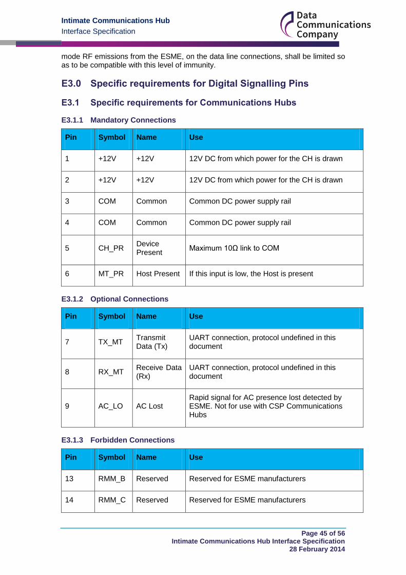
E3.1 Specific requirements for Communications Hubs
E3.1.1 Mandatory Connections
Pin Symbol Name Use
1 +12V +12V 12V DC from which power for the CH is drawn
2 +12V +12V 12V DC from which power for the CH is drawn
3 COM Common Common DC power supply rail
4 COM Common Common DC power supply rail
5 CH_PR Device Present
Maximum 10Ω link to COM
6 MT_PR Host Present If this input is low, the Host is present
E3.1.2 Optional Connections
Pin Symbol Name Use
7 TX_MT Transmit Data (Tx)
UART connection, protocol undefined in this document
8 RX_MT Receive Data (Rx)
UART connection, protocol undefined in this document
9 AC_LO AC Lost Rapid signal for AC presence lost detected by ESME. Not for use with CSP Communications Hubs
E3.1.3 Forbidden Connections
Pin Symbol Name Use
13 RMM_B Reserved Reserved for ESME manufacturers
14 RMM_C Reserved Reserved for ESME manufacturers
Intimate Communications Hub
Interface Specification
Page 46 of 56 Intimate Communications Hub Interface Specification
28 February 2014
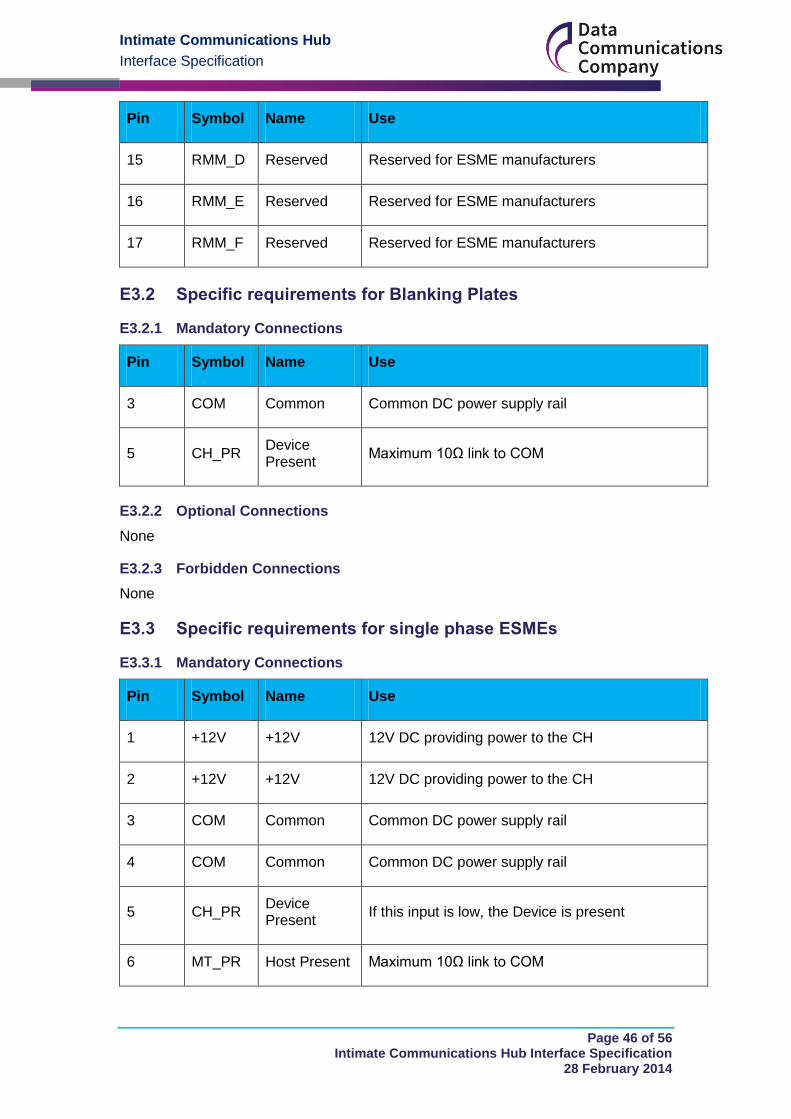
Pin Symbol Name Use
15 RMM_D Reserved Reserved for ESME manufacturers
16 RMM_E Reserved Reserved for ESME manufacturers
17 RMM_F Reserved Reserved for ESME manufacturers
E3.2 Specific requirements for Blanking Plates
E3.2.1 Mandatory Connections
Pin Symbol Name Use
3 COM Common Common DC power supply rail
5 CH_PR Device Present
Maximum 10Ω link to COM
E3.2.2 Optional Connections
None
E3.2.3 Forbidden Connections
None
E3.3 Specific requirements for single phase ESMEs
E3.3.1 Mandatory Connections
Pin Symbol Name Use
1 +12V +12V 12V DC providing power to the CH
2 +12V +12V 12V DC providing power to the CH
3 COM Common Common DC power supply rail
4 COM Common Common DC power supply rail
5 CH_PR Device Present
If this input is low, the Device is present
6 MT_PR Host Present Maximum 10Ω link to COM
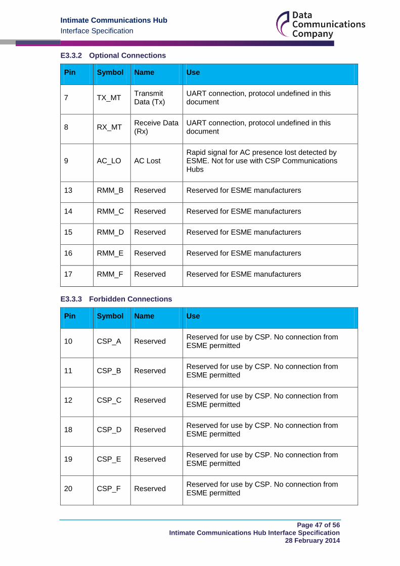
Intimate Communications Hub
Interface Specification
Page 47 of 56 Intimate Communications Hub Interface Specification
28 February 2014
E3.3.2 Optional Connections
Pin Symbol Name Use
7 TX_MT Transmit Data (Tx)
UART connection, protocol undefined in this document
8 RX_MT Receive Data (Rx)
UART connection, protocol undefined in this document
9 AC_LO AC Lost Rapid signal for AC presence lost detected by ESME. Not for use with CSP Communications Hubs
13 RMM_B Reserved Reserved for ESME manufacturers
14 RMM_C Reserved Reserved for ESME manufacturers
15 RMM_D Reserved Reserved for ESME manufacturers
16 RMM_E Reserved Reserved for ESME manufacturers
17 RMM_F Reserved Reserved for ESME manufacturers
E3.3.3 Forbidden Connections
Pin Symbol Name Use
10 CSP_A Reserved Reserved for use by CSP. No connection from ESME permitted
11 CSP_B Reserved Reserved for use by CSP. No connection from ESME permitted
12 CSP_C Reserved Reserved for use by CSP. No connection from ESME permitted
18 CSP_D Reserved Reserved for use by CSP. No connection from ESME permitted
19 CSP_E Reserved Reserved for use by CSP. No connection from ESME permitted
20 CSP_F Reserved Reserved for use by CSP. No connection from ESME permitted
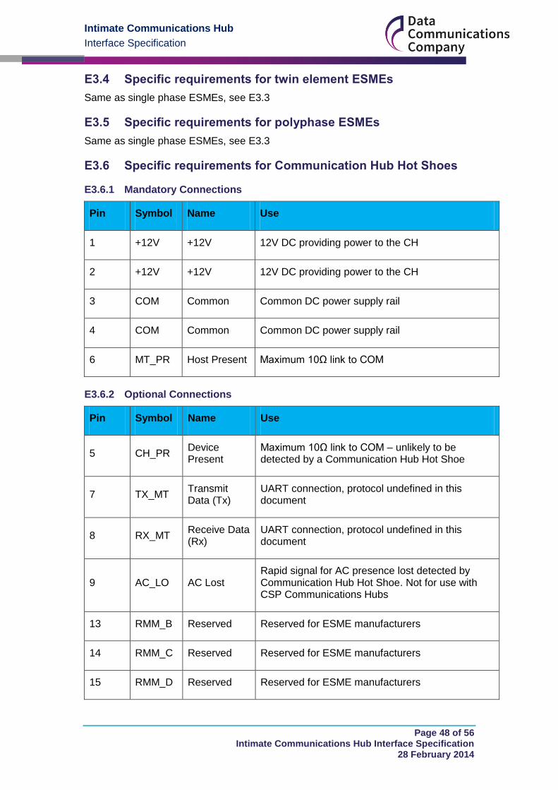
Intimate Communications Hub
Interface Specification
Page 48 of 56 Intimate Communications Hub Interface Specification
28 February 2014
E3.4 Specific requirements for twin element ESMEs
Same as single phase ESMEs, see E3.3
E3.5 Specific requirements for polyphase ESMEs
Same as single phase ESMEs, see E3.3
E3.6 Specific requirements for Communication Hub Hot Shoes
E3.6.1 Mandatory Connections
Pin Symbol Name Use
1 +12V +12V 12V DC providing power to the CH
2 +12V +12V 12V DC providing power to the CH
3 COM Common Common DC power supply rail
4 COM Common Common DC power supply rail
6 MT_PR Host Present Maximum 10Ω link to COM
E3.6.2 Optional Connections
Pin Symbol Name Use
5 CH_PR Device Present
Maximum 10Ω link to COM – unlikely to be detected by a Communication Hub Hot Shoe
7 TX_MT Transmit Data (Tx)
UART connection, protocol undefined in this document
8 RX_MT Receive Data (Rx)
UART connection, protocol undefined in this document
9 AC_LO AC Lost Rapid signal for AC presence lost detected by Communication Hub Hot Shoe. Not for use with CSP Communications Hubs
13 RMM_B Reserved Reserved for ESME manufacturers
14 RMM_C Reserved Reserved for ESME manufacturers
15 RMM_D Reserved Reserved for ESME manufacturers
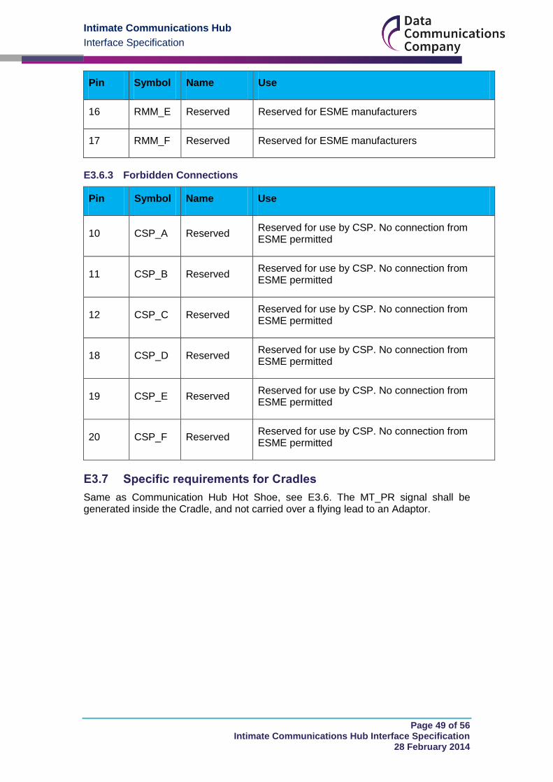
Intimate Communications Hub
Interface Specification
Page 49 of 56 Intimate Communications Hub Interface Specification
28 February 2014
Pin Symbol Name Use
16 RMM_E Reserved Reserved for ESME manufacturers
17 RMM_F Reserved Reserved for ESME manufacturers
E3.6.3 Forbidden Connections
Pin Symbol Name Use
10 CSP_A Reserved Reserved for use by CSP. No connection from ESME permitted
11 CSP_B Reserved Reserved for use by CSP. No connection from ESME permitted
12 CSP_C Reserved Reserved for use by CSP. No connection from ESME permitted
18 CSP_D Reserved Reserved for use by CSP. No connection from ESME permitted
19 CSP_E Reserved Reserved for use by CSP. No connection from ESME permitted
20 CSP_F Reserved Reserved for use by CSP. No connection from ESME permitted
E3.7 Specific requirements for Cradles
Same as Communication Hub Hot Shoe, see E3.6. The MT_PR signal shall be generated inside the Cradle, and not carried over a flying lead to an Adaptor.
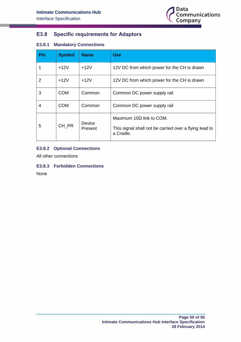
Intimate Communications Hub
Interface Specification
Page 50 of 56 Intimate Communications Hub Interface Specification
28 February 2014
E3.8 Specific requirements for Adaptors
E3.8.1 Mandatory Connections
Pin Symbol Name Use
1 +12V +12V 12V DC from which power for the CH is drawn
2 +12V +12V 12V DC from which power for the CH is drawn
3 COM Common Common DC power supply rail
4 COM Common Common DC power supply rail
5 CH_PR Device Present
Maximum 10Ω link to COM.
This signal shall not be carried over a flying lead to a Cradle.
E3.8.2 Optional Connections
All other connections
E3.8.3 Forbidden Connections
None
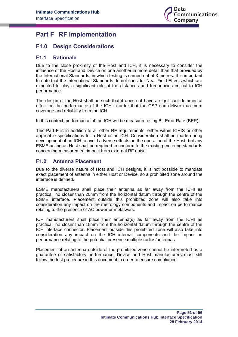
Intimate Communications Hub
Interface Specification
Page 51 of 56 Intimate Communications Hub Interface Specification
28 February 2014
RF Implementation Part F
Design Considerations F1.0
F1.1 Rationale
Due to the close proximity of the Host and ICH, it is necessary to consider the influence of the Host and Device on one another in more detail than that provided by the International Standards, in which testing is carried out at 3 metres. It is important to note that the International Standards do not consider Near Field Effects which are expected to play a significant role at the distances and frequencies critical to ICH performance.
The design of the Host shall be such that it does not have a significant detrimental effect on the performance of the ICH in order that the CSP can deliver maximum coverage and reliability from the ICH.
In this context, performance of the ICH will be measured using Bit Error Rate (BER).
This Part F is in addition to all other RF requirements, either within ICHIS or other applicable specifications for a Host or an ICH. Consideration shall be made during development of an ICH to avoid adverse effects on the operation of the Host, but any ESME acting as Host shall be required to conform to the existing metering standards concerning measurement impact from external RF noise.
F1.2 Antenna Placement
Due to the diverse nature of Host and ICH designs, it is not possible to mandate exact placement of antenna in either Host or Device, so a prohibited zone around the interface is defined.
ESME manufacturers shall place their antenna as far away from the ICHI as practical, no closer than 20mm from the horizontal datum through the centre of the ESME interface. Placement outside this prohibited zone will also take into consideration any impact on the metrology components and impact on performance relating to the presence of AC power or metalwork.
ICH manufacturers shall place their antenna(s) as far away from the ICHI as practical, no closer than 15mm from the horizontal datum through the centre of the ICH interface connector. Placement outside this prohibited zone will also take into consideration any impact on the ICH internal components and the impact on performance relating to the potential presence multiple radios/antennas.
Placement of an antenna outside of the prohibited zone cannot be interpreted as a guarantee of satisfactory performance. Device and Host manufacturers must still follow the test procedure in this document in order to ensure compliance.
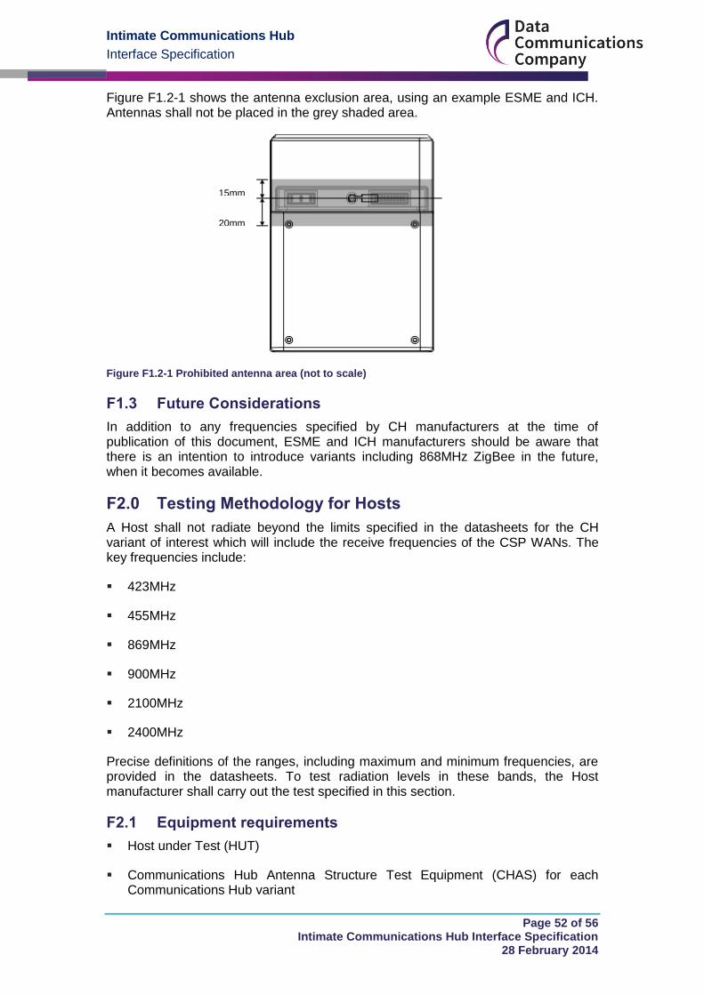
Intimate Communications Hub
Interface Specification
Page 52 of 56 Intimate Communications Hub Interface Specification
28 February 2014
Figure F1.2-1 shows the antenna exclusion area, using an example ESME and ICH. Antennas shall not be placed in the grey shaded area.
Figure F1.2-1 Prohibited antenna area (not to scale)
F1.3 Future Considerations
In addition to any frequencies specified by CH manufacturers at the time of publication of this document, ESME and ICH manufacturers should be aware that there is an intention to introduce variants including 868MHz ZigBee in the future, when it becomes available.
Testing Methodology for Hosts F2.0
A Host shall not radiate beyond the limits specified in the datasheets for the CH variant of interest which will include the receive frequencies of the CSP WANs. The key frequencies include:
423MHz
455MHz
869MHz
900MHz
2100MHz
2400MHz
Precise definitions of the ranges, including maximum and minimum frequencies, are provided in the datasheets. To test radiation levels in these bands, the Host manufacturer shall carry out the test specified in this section.
F2.1 Equipment requirements
Host under Test (HUT)
Communications Hub Antenna Structure Test Equipment (CHAS) for each Communications Hub variant
15mm
20mm
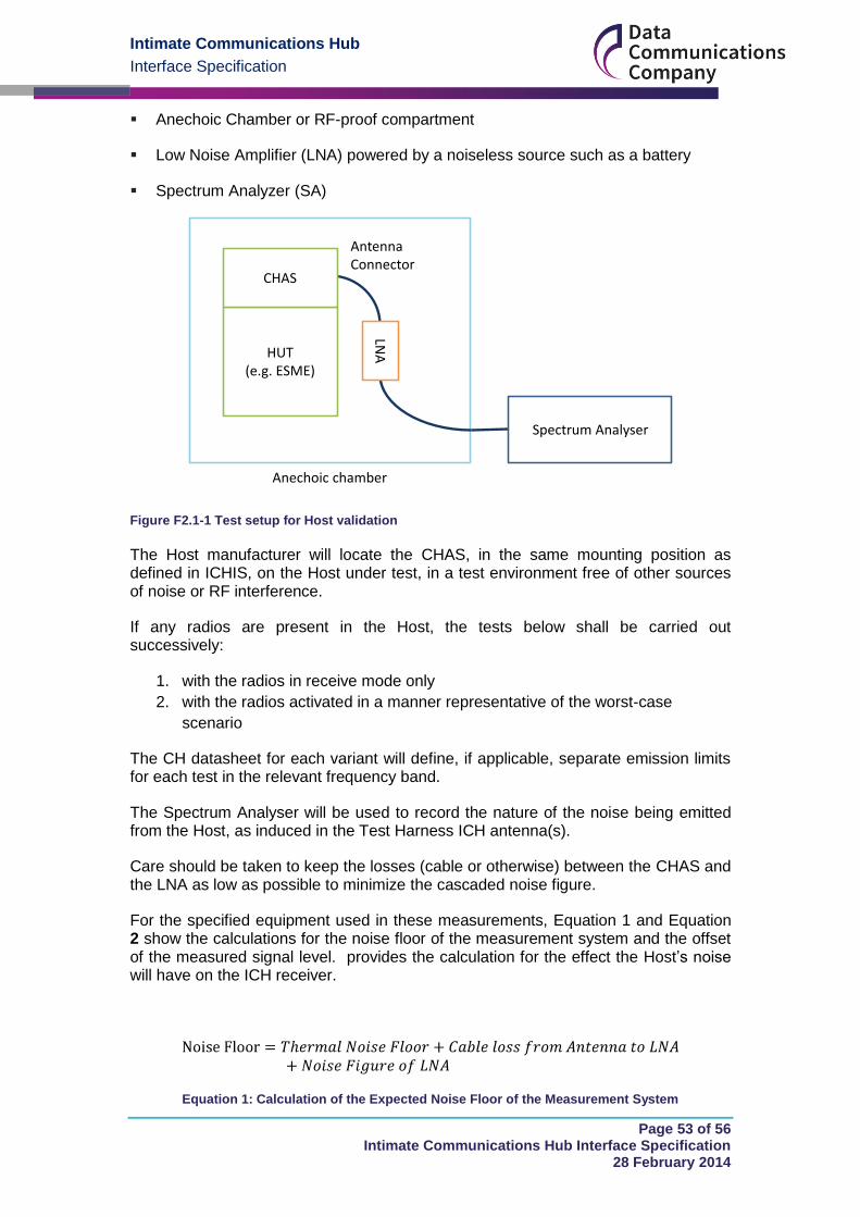
Intimate Communications Hub
Interface Specification
Page 53 of 56 Intimate Communications Hub Interface Specification
28 February 2014
Anechoic Chamber or RF-proof compartment
Low Noise Amplifier (LNA) powered by a noiseless source such as a battery
Spectrum Analyzer (SA)
Figure F2.1-1 Test setup for Host validation
The Host manufacturer will locate the CHAS, in the same mounting position as defined in ICHIS, on the Host under test, in a test environment free of other sources of noise or RF interference.
If any radios are present in the Host, the tests below shall be carried out successively:
1. with the radios in receive mode only
2. with the radios activated in a manner representative of the worst-case
scenario
The CH datasheet for each variant will define, if applicable, separate emission limits for each test in the relevant frequency band.
The Spectrum Analyser will be used to record the nature of the noise being emitted from the Host, as induced in the Test Harness ICH antenna(s).
Care should be taken to keep the losses (cable or otherwise) between the CHAS and the LNA as low as possible to minimize the cascaded noise figure.
For the specified equipment used in these measurements, Equation 1 and Equation 2 show the calculations for the noise floor of the measurement system and the offset of the measured signal level. provides the calculation for the effect the Host’s noise will have on the ICH receiver.
Equation 1: Calculation of the Expected Noise Floor of the Measurement System
CHAS
HUT(e.g. ESME)
LNA
Spectrum Analyser
Antenna Connector
Anechoic chamber
Intimate Communications Hub
Interface Specification
Page 54 of 56 Intimate Communications Hub Interface Specification
28 February 2014
Equation 2: Calculation of the Signal Level Offset
F2.2 RF Isolation Recommendations
Care must be taken to prevent accidentally extending or altering the radiating structures or the HUT and CHAS’s environment.
The CHAS’s coaxial connection shall be isolated from common-mode currents , e.g. by placing ferrite beads along the coaxial cabling as close to the antenna as possible. Without this precaution, the cable itself could become part of the radiating structure and alter the measurement results.
The HUT’s power connections should originate from a filtered 230V 50Hz AC power source. These wires should include clamp-on ferrite beads every 30cm to prevent any portion of the wiring from being an efficient antenna that could re-radiate the signals being measured. If the Host is an ESME, the tests below shall be performed according to the measurement setup description in the relevant CH datasheet.
The CHAS shall be connected to the HUT’s ground and DC power supply pins through the ICHI data connector. The CHAS shall provide a resistive load on the ICHI DC power connector which draws from the HUT’s power supply.
F2.3 Test Setup Requirements
In the condition where the HUT is not powered, the following test environment conditions shall apply.
The noise of the measurement system (LNA noise figure + cable loss before LNA) shall be below 1.5dB when performing the tests.
The absolute level of the thermal noise (Equation 1 above) shall be within ±3dB of the Expected Noise Floor.
F2.4 Determining levels
Specific settings for the Spectrum Analyser will be provided in the CH datasheet. These settings may change between CH variants and frequency bands, and shall be used for both background noise and active noise checks.
With the HUT unpowered, the background noise level shall be measured in each frequency band of the relevant CHAS, ensuring that they are within the limits specified in F2.3.
The HUT shall then be powered on and left to warm up and settle for 10 minutes, including the DC power supply and any AC power loads drawn. The noise floor shall be measured and recorded.
The noise measurement for each frequency band shall then be compared against the limits in the datasheets for the CH variant of interest. These datasheets will be published via the SmartDCC Ltd website.
Intimate Communications Hub
Interface Specification
Page 55 of 56 Intimate Communications Hub Interface Specification
28 February 2014
Recommendations for ESME transmission on the HAN F3.0
To reduce the likelihood of front end overload on the Communications Hub HAN radio, an ESME which has an ICH mounted to it should maintain transmission levels to the lowest level possible, relying on the ZigBee Meshing through the Communications Hub for message transmissions to other HAN products. It is recommended that the ESME use ZigBee received signal strength to detect the presence of an ICH. Power drain from the ICHI cannot be relied upon to provide this detection due to the possibility of an Adapter, flying lead and Cradle arrangement.
Intimate Communications Hub
Interface Specification
Page 56 of 56 Intimate Communications Hub Interface Specification
28 February 2014
Security Part G
Physical security G1.0
G1.1 Mechanical security
Mechanical security for the ICHIS is provided by the sealing screw, as defined in sections B1.6.1 and B1.6.2. Tamper Evident labels may also be applied to the interface between the Host and ICH, and ESME and Device, if desired.
G1.2 Tamper detection
Electronic tamper detection for the Host and Device is provided by the means described in section E3.0.
G1.3 Scope of secure perimeter
The secure perimeter has been defined as covering only Hosts and Devices which are directly connected. As such, it excludes any flying lead between an Adaptor and Cradle, but will detect removal of the CH from the Cradle, or the Adaptor from the ESME.
Out of scope areas G2.0
This specification does not cover security of any protocols used to communicate with either the ESME or ICH. This includes any protocols used over ZigBee HAN, SMWAN or wired HAN (including PLC), as well as any custom interfaces offered by the ESME or ICH for manufacturer purposes.
No consideration is made for other interfaces offered by an ICH or ESME, for instance a port for an external aerial. Such interfaces shall be secured appropriately by the ICH or ESME manufacturer.