Interpretare IEC 60364 .7
31
1 Healthcare interpretation of IEE Guidance Note 7 (Chapter 10) and IEC 60364-7-710 for Electrical Installations in Medical Locations Annex to MEIGaN June 2005 Queries concerning this document should be directed to: [email protected] The Engineering Team Quarry House 3N 34B Leeds LS2 7UE
description
Interpretare IEC 60364 .7.710
Transcript of Interpretare IEC 60364 .7
1
Healthcare interpretation of IEE
Guidance Note 7 (Chapter 10) and IEC 60364-7-710
for
Electrical Installations in Medical Locations
Annex to MEIGaN
June 2005 Queries concerning this document should be directed to: [email protected] The Engineering Team Quarry House 3N 34B Leeds LS2 7UE
2
Contents 1 INTRODUCTION 1.1 OUTLINE 1.2 BACKGROUND 2 MEDICAL LOCATIONS 2.1 FOREWORD 2.2 GENERAL 2.3 SCOPE 2.4 DEFINITIONS 2.5 ASSESSMENT OF GENERAL CHARACTERISTICS 2.6 TYPES OF SYSTEM EARTHING 2.7 PROTECTION AGAINST DIRECT AND INDIRECT CONTACT 2.8 PROTECTION AGAINST DIRECT CONTACT 2.9 PROTECTION AGAINST INDIRECT CONTACT 2.10 MEDICAL IT (IPS) SYSTEM 2.11 TRANSFORMERS FOR MEDICAL IT (IPS) SYSTEMS 2.12 MEDICAL IT (IPS) SYSTEMS FOR GROUP 2 MEDICAL LOCATIONS 2.13 SUPPLEMENTARY EQUIPOTENTIAL BONDING 2.14 FIRE PROTECTION 2.15 EXTERNAL INFLUENCES 2.16 EXPLOSION RISK 2.17 DIAGRAMS, DOCUMENTATION AND OPERATING INSTRUCTIONS 2.18 WIRING SYSTEMS
3
2.19 PROTECTION OF WIRING SYSTEMS IN MEDICAL LOCATIONS OF GROUP 2 2.20 GENERAL REQUIREMENTS FOR POWER SUPPLIES FOR SAFETY SERVICES 2.21 DETAILED REQUIREMENTS FOR SAFETY POWER SUPPLY SERVICES 2.21.1 Power supply sources with a change-over period less than or equal to 0.5 s 2.21.2 Power supply sources with a change-over period less than or equal to 15 s 2.21.3 Power supply sources with a changeover period greater than 15 s 2.22 SOCKET-OUTLET CIRCUITS IN THE MEDICAL IT (IPS) SYSTEM FOR MEDICAL LOCATIONS OF GROUP 2 2.23 LIGHTING CIRCUITS 2.23.3 Safety lighting 2.24 VERIFICATION 2.24.1 Initial verification 2.24.2 Periodic verification 3 ASSOCIATED INFORMATION AND DRAWINGS Part `A` Examples of allocation of group numbers and classification for safety services of medical locations including definitions of medical locations listed in table. Part `B` Guidance on the classification of safety services for medical locations Drawing `C` Example of patient environment Drawing `D` Typical theatre layout Drawing `E` Typical final circuit distribution – Medical IT (IPS) system Part “C” References

4
1.0 INTRODUCTION 1.1 OUTLINE 1.1.1 This annex is an appraisal of current electrical standards in support of the main MEIGaN document and is intended to provide associated guidance and interpretation. It is not a full repeat of all text in the referenced documents and some statements have been excluded, to improve the clarity of understanding. 1.1.2 At the time of publication current HTM documents have been referenced however it should be noted that a review of guidance is currently in progress. On completion this annex will be removed from the MEIGaN document and be replaced with a reference to the new HTM guidance. 1.2 BACKGROUND 1.2.1 HTM 2007 and HTM 2011 are the most comprehensive documents available from NHS Estates covering low and extra-low voltage installations. HTM 2007 (published in 1993) emphasises that a hospital electrical distribution system should be designed to provide security of supply and flexibility and safety in operation. Its technical recommendations are in-line with BS 7671. 1.2.2 The Design Considerations volume of HTM 2007, paragraphs 11.94 & 11.95, refers to a forthcoming IEC standard 364-710 for medical locations. 1.2.3 BS 7671: 2001 `Requirements for electrical installations. IEE Wiring Regulations. Sixteenth edition` reserves section 610 in its Part 6 (Special Installations or Locations) for future use. This will most likely be for `Medical Locations`. 1.2.4 The most up-to-date international standard for electrical installations in medical locations is published in IEC 60364-7-710. This standard was developed with full participation of the British Electrotechnical Committee where the IEE and the UK Health Departments had a major input in its final approval. This document was published in November 2002. 1.2.5 IEE Guidance Note 7 (Chapter 10) covers the special requirements for medical locations. It was first published in 1998 and revised in 2003. The latter publication is based on IEC 60364-7-710 for medical locations. 1.2.6 Other relevant guidance material available: - NHS Model Engineering Specifications (MES). - Health Building Notes. - Scottish Health Planning Notes - Activity DataBase (ADB). - Design Guides. - Engineering Data Sheets.
5
2.0 MEDICAL LOCATIONS 2.1 FOREWORD 2.1.1 These explanatory notes are based on the international standard for medical locations as detailed in IEC 60364-7-710. The latter forms the basis of IEE Guidance Note 7 - Chapter 10 `Medical Locations`. 2.1.2 The fundamental clauses of the IEC standard are listed and, where necessary, ` Notes` are included to amplify the content. 2.1.3 Some of the listed clauses of the IEC standard have been edited for clarity. 2.1.4 The following is also included: - Advice on the type of hospital rooms where special electrical installations are necessary. - Essential variations to HTM 2007 and HTM 2011. - Listing of typical distribution layouts. - Comprehensive definitions. - References
6
2.2 GENERAL 2.2.1 The requirements of IEC 60364-7-710 supplement, modify or replace certain of the general requirements as contained in parts 1 to 6 of IEC 60364. Note: The IEE Wiring Regulations (16th edition) mirrors IEC 60364 in many respects. The difference is where the IEC document lists its Requirements for Special Installations or Locations in Part 7, the IEE lists them in Part 6. 2.2.2 The absence of reference to a part or a clause means that parts 1 to 6 of IEC 60364 are applicable. Note: This practice is also implemented in the IEE Wiring Regulations where the absence of a reference to a chapter or section in Part 6 implies that the Regulations in Parts 1 to 5 are applicable. It must be emphasised that the Requirements for Special Installations or Locations are not stand-alone documents. They must be read in conjunction with the main body of the Regulations. 2.2.3 In medical locations it is necessary to ensure the safety of patients likely to be subjected to the application of medical electrical equipment. Safety can be achieved by ensuring the safety of the installation and the safe operation and maintenance of medical electrical equipment connected to it. The use of medical electrical equipment on patients undergoing intensive care has called for enhanced reliability and safety of electrical installations in hospitals so as to improve the safety and continuity of supplies which is met by application of this document. Variations of the standard to further enhance safety and reliability are acceptable. 2.3 SCOPE 2.3.1 The requirements of IEC 60364-7-710 apply to electrical installations in medical locations so as to ensure safety of patients and medical staff. These requirements, in the main, refer to hospitals, private clinics, medical and dental practices, health care centres and dedicated medical rooms in the work place. 2.3.2 It may be necessary to modify the existing electrical installation, in accordance with this document, when a change of utilization of the location occurs. 2.3.3 The requirements of this document do not apply to medical electrical equipment. For the latter reference should be made to the IEC 60601 series. Note: The BS EN 60601 series mirror the IEC 60601 series.
7
2.4 DEFINITIONS 2.4.1 Medical location Location intended for purposes of diagnosis, treatment (including cosmetic treatment), monitoring and care of patients. 2.4.2 Patient Living person undergoing medical or dental investigation or treatment. The person under treatment for cosmetic purposes may be considered, as far as this standard is concerned, as a patient. Note: Definition adapted from IEC 60601-1 (BS EN 60601-1). 2.4.3 Medical electrical equipment Electrical equipment, provided with not more than one connection to a particular supply mains and intended to diagnose, treat or monitor the patient under medical supervision and which: - Make physical or electrical contact with the patient; and/or - Transfer energy to or from the patient; and/or - Detect such energy transfer to or from the patient. The equipment includes those accessories defined by the manufacturer as being necessary to enable the normal use of the equipment. Note: Definition adapted from IEC 60601-1 (BS EN 60601-1). Medical devices in the UK are regulated by the Medicines and Healthcare products Regulatory Agency (MHRA). MHRA use the Medical Device Regulations as part of their remit to regulate medical devices.
Note: To ensure protection of patients from possible electrical hazards, additional protective measures need to be applied in medical locations. The type and description of these hazards can vary according to the treatment being administered. The manner in which a room is to be used necessitates some division into different areas for differing medical procedures.
8
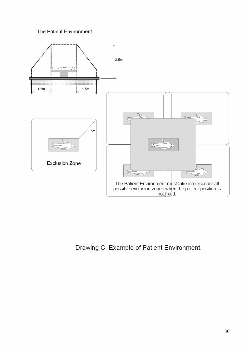
2.4.4 Applied part Part of the medical electrical equipment which in normal use: - Necessarily comes into physical contact with the patient for the equipment to perform its function; or - Can be brought into contact with the patient; or - Needs to be touched by the patient. Note: Definition adapted from IEC 60601-1 (BS EN 60601-1). 2.4.5 Group 0 Medical location where no applied parts are intended to be used. Note: For example consultant examination room. 2.4.6 Group 1 (As referenced for MEIGaN) Medical location where discontinuity of supply is not a threat to human life except where 2.4.7.applies Note: See Appendix`A` 2.4.7 Group 2 (As referenced for MEIGaN) Medical location where discontinuity (failure) of the supply can cause danger to life. 2.4.8 Medical electrical system Combination of items of equipment, at least one of which must be medical electrical equipment and inter-connected by functional connection or use of a multiple portable socket-outlet. The system includes those accessories which are needed for operating the system and are specified by the manufacturer. Note: Definition adapted from IEC 60601-1-1 (BS EN 60601-1-1) where definitions of `functional connection` and `multiple portable socket-outlets` are included. 2.4.9 Patient environment Any volume in which intentional or unintentional contact can occur between patient and parts of the system or between patient and other persons touching parts of the system . Note: Definition adapted from IEC 60601-1-1(BS EN 60601-1-1). This applies when the patient’s position is pre-determined, if not, all possible patient positions should be considered. For illustration see drawing “C”
9
2.4.10 Main distribution board Board in the building which fulfils all the functions of a main electrical distribution for the supply building area assigned to it and where the voltage drop is measured for operating the safety services. 2.4.11 Medical IT (IPS) system IT electrical system having specific requirements for medical applications. Note: The term IT should not be confused with `Information Technology`. The IEE Wiring Regulations (BS 7671) defines different distribution systems as follows: IT: “A systems having no direct connection between live parts and Earth, the exposed-conductive-parts of the electrical installation being earthed”. This, in single-phase applications, means that the output of the isolating transformer is floating and no reference to earth exists. TN-S: “A system having separate neutral and protective conductors throughout the system”. TT: “A system having one point of the source energy directly earthed, the exposed –conductive-parts of the electrical installation being connected to earth electrodes electrically independent of the earth electrodes of the source. TN-C: “A system in which neutral and protective functions are combined in a single conductor throughout the system”. 2.4.12 IPS (Isolated Power Supply) This system should be considered as an IT supply together with a monitoring device with an alarm for disconnection, insulation failure, overload and high temperature.
10
2.5 ASSESSMENT OF GENERAL CHARACTERISTICS 2.5.1 Allocation of group numbers and classification of safety services to a medical location shall be made in agreement with the medical staff and the body responsible for safety. In order to determine the classification of a medical location, it is necessary that the medical staff indicate which medical procedures will take place within the location. Based on the intended use, the appropriate classification for the location shall be determined. Note: Guidance on the allocation of a group number and classification of safety service for a medical location is shown in Section 3 Associated Information Part “A” The possibility that certain medical locations may be used for different purposes which necessitate a higher group allocation should be addressed by risk management. 2.6 TYPES OF SYSTEM EARTHING 2.6.1 The TN-C system is not allowed in medical locations and medical buildings downstream of the main distribution board. Note: The Electricity Safety, Quality and Continuity Regulations 2002 prevents the use of TN-C system in any part of a consumer’s installation. As an example,load and earth fault currents associated with TN-C systems can circulate through the casing of Class I equipment thus causing electromagnetic interference with sensitive electronic medical equipment..
11
2.7 PROTECTION AGAINST DIRECT AND INDIRECT CONTACT 2.7.1 Protection by extra-low voltage: SELV and PELV 2.7.1.1 When using SELV and/or PELV circuits in medical locations of group 1 and group 2, the nominal voltage applied to current-using equipment shall not exceed 25 V r.m.s. a.c. or 60 V ripple free d.c. Protection by insulation of live parts and by barriers or enclosures is essential. Note: The nominal limits for Separated Extra Low Voltage (SELV) and Protected Extra Low Voltage (PELV) is 50 V a.c and 120 V ripple free d.c. However, as prescribed by IEC 60601-1 this limit is reduced to 25 V a.c. and 60 V ripple free d.c. when these systems are used in medical locations of group 1 and group 2. Normally protection by insulation of live parts and by barriers or enclosures applies only to SELV systems where the nominal voltage exceeds 25 V a.c. or 60 V ripple free d.c. What is implied here is that this type of protection is essential even when the nominal voltage does not exceed 25 V a.c. or 60 V ripple free d.c. 2.7.1.2 In medical locations of group 2, exposed-conductive-parts of equipment (e.g. operating theatre luminaires), shall be connected to the equipotential bonding conductor. Note: In normal applications, exposed-conductive-parts of `SELV` or `PELV` equipment are kept free from any connection to earth. The implication here is that in group 2 locations the exposed-conductive-parts of `SELV` equipment such as operating theatre luminaries should be connected to the equipotential bonding conductor. Theatre luminaries are normally supplied from the TN-S system via a safety isolating transformer. 2.8 PROTECTION AGAINST DIRECT CONTACT 2.8.1 Protection by obstacles 2.8.1.1 Protection by obstacles is not permitted. Note: In normal applications, the use of obstacles can be used as a measure for protection against direct contact with live parts where the application is limited to an area accessible only to skilled person, or to instructed person under the direct supervision of a skilled person. 2.8.2 Protection by placing out of reach 2.8.2.1 Protection by placing out of reach is not permitted. Note: In normal applications, placing out of reach can be used as a measure for protection against direct contact with live parts where the application is limited to an area accessible only to skilled person, or to instructed person under the direct supervision of a skilled person. 2.8.3 Protection by insulation of live parts or by barriers or enclosures
2.8.3.1 This is the only type of protection permitted.
12
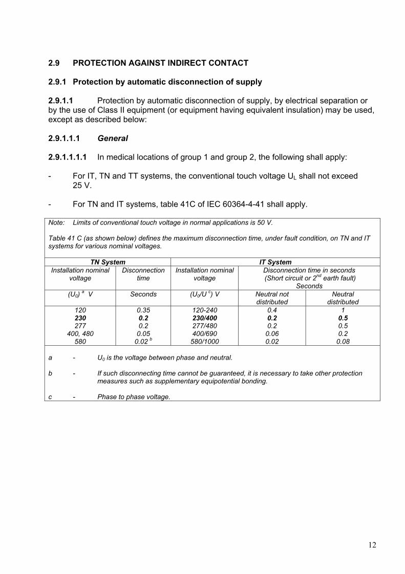
2.9 PROTECTION AGAINST INDIRECT CONTACT 2.9.1 Protection by automatic disconnection of supply 2.9.1.1 Protection by automatic disconnection of supply, by electrical separation or by the use of Class II equipment (or equipment having equivalent insulation) may be used, except as described below: 2.9.1.1.1 General 2.9.1.1.1.1 In medical locations of group 1 and group 2, the following shall apply: - For IT, TN and TT systems, the conventional touch voltage UL shall not exceed 25 V. - For TN and IT systems, table 41C of IEC 60364-4-41 shall apply. Note: Limits of conventional touch voltage in normal applications is 50 V. Table 41 C (as shown below) defines the maximum disconnection time, under fault condition, on TN and IT systems for various nominal voltages.
TN System IT System Installation nominal
voltage Disconnection
time Installation nominal
voltage Disconnection time in seconds (Short circuit or 2nd earth fault)
Seconds (U0) a V Seconds (U0/U c) V Neutral not
distributed Neutral
distributed 120 230 277
400, 480 580
0.35 0.2 0.2
0.05 0.02 b
120-240 230/400 277/480 400/690 580/1000
0.4 0.2 0.2
0.06 0.02
1 0.5 0.5 0.2 0.08
a - U0 is the voltage between phase and neutral. b - If such disconnecting time cannot be guaranteed, it is necessary to take other protection measures such as supplementary equipotential bonding. c - Phase to phase voltage.
13
2.9.1.1.2 TN systems 2.9.1.1.2.1 In final circuits of medical locations of group 1 rated up to 32 A residual current devices (RCD) with a maximum residual operating current of 30 mA shall be used. Note: This implies that all socket-outlets in group 1 locations should be protected by RCDs. 2.9.1.1.2.2 In medical locations of group 2, protection by automatic disconnection of supply by means of residual current protective devices with the rated residual operating current not exceeding 30 mA shall only be used on the following circuits: - Circuits for the supply of operating tables. Note: The mechanism controlling its movement. - Circuits for X-ray units. - Circuits for large equipment with a rated power greater than 5 kVA. - Circuits for non-critical electrical equipment (non life-support). Note: Circuits used for connecting medical electrical equipment or medical systems for life-support and surgical applications in the patient environment should be supplied from the medical IT system. Conventional RCD protection is not suitable on final circuits supplied from the medical IT system . On single (first) fault condition a low capacitive current (a few mA) will flow to earth which is insufficient to trip a 30 mA RCD. Under double fault conditions the RCD would not trip as no imbalance is detected. Care shall be taken to ensure that simultaneous use of many items of such equipment connected to the same circuit cannot cause unwanted tripping of the residual current protective device (RCD). Note: The standard also recommends that TN-S systems are monitored to ensure the insulation level of all live conductors. This recommendation ensures that any inadvertent short circuit between the earth and neutral conductor, thus creating a TN-C system, is identified. This recommendation is not a mandatory requirement by the standard. 2.9.1.1.2.3 In medical locations of group 1 and group 2, where RCDs are required, only type A or type B shall be selected, depending on the possible fault-current arising. Note: Type `A` ensures tripping for residual sinusoidal alternating currents and residual pulsating direct currents; whether suddenly applied or slowly rising. Type `B` ensures tripping for residual sinusoidal alternating currents and residual pulsating direct currents and smooth direct currents.. 2.9.1.1.3 TT systems 2.9.1.1.3.1 In medical locations of group 1 and group 2, the requirements of TN systems shall apply and in all case RCDs shall be used.
14
2.10 MEDICAL IT (IPS) SYSTEM 2.10.1 In Medical Locations of group 2, the medical IT (IPS) system shall be used for circuits supplying medical electrical equipment and systems intended for life support, surgical applications and other electrical equipment located in the 'Patient Environment', excluding equipment listed in 2.9.1.1.2.2 Note: The medical IT(IPS) system is represented by an isolating transformer, an Insulation Monitoring Device (IMD) and the controlgear and wiring associated with it. The use of isolating transformers creates a safer environment to the patient and staff by minimising hazards from touch voltages and ensuring continuity of supply under single fault conditions. Isolating Transformers alone are not intended to protect against microshock and must be associated with circuit monitoring, supplementary equipotential earth bonding and an assessment of the treatment area. The output of the isolating transformer is kept free from any earth connection. This concept affords better protection from potentially lethal shock hazards due to the absence of a low impedance earth return path. However, due to the capacitance of the line conductors to earth, there will always be a capacitive current flow to earth. Details of group 2 locations are shown in Associated information Part `A` 2.10.2 For each group of rooms serving the same function, at least one separate medical IT (IPS) system is necessary. The medical IT (IPS) system shall be equipped with an insulation monitoring device in accordance with IEC 61557-8 with the following additional requirements: - The internal impedance shall be at least 100 kΩ. - The test voltage shall not be greater than 25 V d.c. - The test current shall, even under fault conditions, not be greater than 1 mA peak. - Indication shall take place at the latest when the insulation resistance has decreased to 50 kΩ. A test device shall be provided. Note: Insulation Monitoring Devices (IMD) are an integral part of IT(IPS) systems. IEC 61557-8 is equivalent to BS EN 61557-8. These additional requirements are not at present covered by IEC 61557-8. They would be omitted once they are included in further editions of IEC 61557-8. IMDs are active devices monitoring continuously the insulation of the circuits connected to them; even if these circuits are not carrying any load current. In contrast to RCDs, being passive devices, their activation can only be achieved when the circuits are loaded.
15
2.10.3 For each medical IT (IPS) system, an acoustic and visual alarm system incorporating the following components shall be arranged at a suitable place so that it can be permanently monitored (audible and visual signals) by the medical staff: Note: The audible and visual alarms are intended for the attention of medical staff, not the patients, hence it is recommended that the monitoring panel is placed either within the group 2 location or at an adjacent manned location such as a staff base.. - A green signal lamp to indicate normal operation. - A yellow signal lamp which lights when the minimum value set for the insulation resistance is reached. It shall not be possible for this light to be cancelled or disconnected. - An audible alarm which sounds when the minimum value set for the insulation resistance is reached. This audible alarm may be silenced. - The yellow signal shall go out on removal of the fault and when the normal condition is restored. 2.10.4 Where an equipment is supplied from one single dedicated IT transformer, the latter can be installed without an insulation monitoring device. Note: The type of equipment referred to here is normally connected permanently, i.e. fixed, where the IT transformer would have been rated by the designer to suite the single load connected to it. An example of this is an X-ray unit or a laser. This should not be interpreted that one can terminate this final circuit with a single socket-outlet where loads connected to the latter are not pre-determined. 2.10.5 Monitoring of overload and high temperature for the medical IT transformer is required. Note: Transformers can withstand at least 10% overload for a prescribed period. An indication of the limit being reached avoids excessive overloading. Although high temperature is normally associated with overload, it can also occur in non-ventilated enclosures. 2.11 TRANSFORMERS FOR MEDICAL IT (IPS) SYSTEMS 2.11.1 Transformers shall be installed in close proximity to, inside or outside, the medical location and placed in cabinets or enclosures to prevent unintentional contact with live parts. The rated voltage Un on the secondary side of transformers shall not exceed 250 V a.c Note: Transformers should be placed in well ventilated enclosures and cannot be located within MRi Scanner Faraday Cage's because of interference with the static magnetic field. The maximum limit of the output rated voltage allowed by the IEC for a medical IT transformer, either single-phase or 3-phase (line to line) applications, is limited to 250 V a.c. (refer to IEC 61558-2-15: 1998).
16
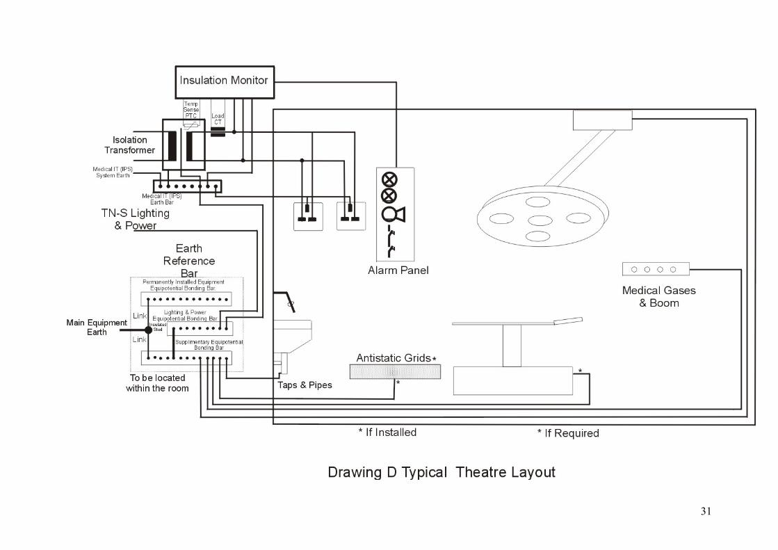
2.12 MEDICAL IT (IPS) SYSTEMS FOR GROUP 2 MEDICAL LOCATIONS 2.12.1 Transformers shall be in accordance to IEC 61558-2-15 with the following additional requirements: Note: BS EN 61558-2-15 is equivalent in many respects to IEC 61558-2-15 2.12.2 The leakage current of the output winding to earth and the leakage current of the enclosure, when measured in no-load condition and the transformer supplied at rated voltage and rated frequency, shall not exceed 0.5 mA. Note: It is essential that this requirement for leakage currents is specified as an additional requirement to IEC 61558-2-15. As it stands, IEC 61558-2-15 specifies these leakage currents to a limit of 3.5 mA, however there are moves in hand to modify IEC 61558-2-15 to reduce the leakage currents specified to 0.5 mA. This requirement enhances the safety applications of the transformer and brings it in line with IEC 60601-1. 2.12.3 Single-phase transformers shall be used to form the medical IT (IPS) systems for portable and fixed equipment and the rated output shall not be less than 0.5 kVA and shall not exceed 10 kVA. Note: The upper limit is recognised to be the maximum that can be achieved for economically constructed transformers where the prescribed percentage impedance does not exceed 3 %. 2.12.4 If the supply of three-phase loads via an IT (IPS) system is also required, a separate three-phase transformer shall be provided for this purpose with output line to line voltage not exceeding 250 V. Note: Such a transformer will not provide a line/neutral supply as customary with distribution three phase transformers. 2.13 SUPPLEMENTARY EQUIPOTENTIAL BONDING 2.13.1 In each medical location of group 1 and group 2, supplementary equipotential bonding conductors shall be installed and connected to the earth reference bar (ERB) for the purpose of equalizing potential differences between the following parts, located in the 'patient environment': - Protective conductors. - Extraneous-conductive-parts. - Screening against electrical interference fields, if installed. - Connection to conductive floor grids, if installed. - Metal screen of the isolating transformer, if any. Note: Fixed conductive non-electrical patient supports such as operating theatre tables and dental chairs should be connected to the equipotential bonding conductor unless they are intended to be isolated from earth.
17
2.13.2 In medical locations of Group 2, where intracardiac procedures may take place the resistance of the conductors, including the resistance of the connections, between the terminals for the protective conductor of socket-outlets and of fixed equipment or any extraneous-conductive-parts shall not exceed 0.2 Ω. Note: This ensures that the maximum permissible potential difference between the exposed-conductive-parts of medical electrical equipment and the ERB remain within the limits designated for group 2 locations, normally below 50 mV.to socket outlets. 2.13.3 The ERB shall be located in the medical location, an additional equipotential bonding bar shall be provided to which the supplementary equipotential bonding conductor and protective earth conductor shall be connected. Connections shall be so arranged that they are clearly visible and easily disconnected individually. Note: See Additional information Drawing `D` The ERB (referred to in Drawing D as “earth reference bar”) is located within the vicinity of the group 2 location to allow short lengths of earthing cables to be connected (say 6 mm2) where the resistive values remain within the 0.2 Ω. The additional earth reference bar referred to in Drawing D may be located some distance away from the group 2 location within the vicinity of the distribution board of the IT (IPS) transformer panel. This allows the connection between these two boards to be made by a larger size earthing cable (say 10 mm2) 2.14 FIRE PROTECTION 2.14.1 Reference should be made to NHS Estates publications `Firecode` series. 2.15 EXTERNAL INFLUENCES 2.15.1 Where appropriate, attention should be given to prevention of electromagnetic interference. Note: Refer to NHS Estates guidance in HTM 2014 2.16 EXPLOSION RISK 2.16.1 Requirements for medical electrical equipment for use in conjunction with flammable gases and vapours are contained of IEC 60601-1. 2.16.2 Where hazardous conditions are likely to occur, e.g. in the presence of flammable gases and vapours, special precautions may be required. Prevention of build-up of static electricity is recommended. Note: Refer to NHS Estates guidance HTM 2025 (SHTM 2025 in Scotland) and HGN `Static discharges` 2.16.3 Electrical devices (e.g. socket-outlets and switches) shall be installed at a distance of at least 0.2 m horizontally (centre to centre) from any medical gas-outlets. Note: This requirement is specified in BS EN 793: 1998 `Particular requirements for safety of medical supply units`. It requires that "Terminal units for oxidizing medical gases, for anaesthetic gas scavenging systems and for liquids, shall be located at least 0,2 m from any mains socket outlet."
18
2.17 DIAGRAMS, DOCUMENTATION AND OPERATING INSTRUCTIONS 2.17.1 Plans of the electrical installation together with records, drawings, wiring diagrams and modifications thereto, as well as instructions for operation and maintenance, shall be provided for the user. Note: Wirings and wiring diagrams should be in accordance with IEC 60617-1, IEC 60617-2, IEC 60617-3 IEC 60617-6, IEC 60617-7, IEC 60617- 8 and IEC 61082-1. These standards are equivalent to BS EN 60617 series and BS EN 61082 series. 2.18 WIRING SYSTEMS 2.18.1 Any wiring system within medical locations of Group 2 shall be exclusive to the use of equipment and fittings in that location. Note: This implies that only wiring necessary to supply the equipment situated in the group 2 location is installed. Wiring systems are defined by the IEE Wiring Regulations as “An assembly made up of cable or bus-bars and parts which secure and, if necessary, enclose the cable or bus-bars”. 2.19 PROTECTION OF WIRING SYSTEMS IN MEDICAL LOCATIONS OF GROUP 2 2.19.1 Protection against overload current and short circuit is required for each final circuit of both TN-S and IT distribution system. Overload current protection is not allowed in the main feeder circuits upstream and downstream of the medical IT (IPS) transformer. Fuses may be used for short circuit protection only. Note: The first sentence describes the type of protection, normally provided by MCBs in the final circuits. The IEE Wiring Regulations defines a final circuit as “a circuit connected directly to current-using equipment, or to a socket-outlet (radial feed) or socket-outlets (ring mains) or other outlet points for the connection of such equipment”. The second sentence stipulates that only short circuit protection is necessary for the main in-feed/out-feed of the medical IT transformer because “overloads” and “temperature” are continually monitored by the IMD where both audible and visual alarms indicate that action need to be taken to disconnect excessive load. The third sentence stipulates that fuses can only be used for short circuit protection and not for overloads (final circuits) due to their prolonged tripping time.
19
2.20 GENERAL REQUIREMENTS FOR POWER SUPPLIES FOR SAFETY SERVICES 2.20.1 In medical locations the distribution system should be designed and installed to facilitate the automatic change-over from the main distribution network to the electrical safety source feeding essential loads. 2.20.2 General requirements for safety power supply sources of group 1 and group 2 locations 2.20.2.1 In medical locations, a power supply for safety services is required which, in case of a failure of the normal power supply source, shall be energized to feed the equipment stated in 2.21.1.1, 2.21.2.1 and 2.21.3.1 with electrical energy for a defined period of time and within a pre-determined changeover period. Note: Safety power supply sources are synonymous with emergency supply sources in UK hospitals. They can be the emergency generator, UPS system or banks of batteries. Classification of safety services for medical locations are given in “Additional information part “A” 2.20.2.2 If the voltage at the main distribution board drops at one or several line conductors by more than 10% of the nominal voltage, a safety power supply source shall assume the supply automatically. Note: It is recommended that the start-up of the emergency generator incorporates a preset delay to cater for transient voltage dips and auto re-closure of the Regional Electricity Company’s main incoming circuit breakers (short-time interruptions) where the delay is of the order of 3 seconds. 2.20.2.3 For interconnecting cables between the individual components and sub-assemblies of safety power supply sources, see 2.18. Note: The circuit which connects the power supply source for safety services to the main distribution board should be considered a safety circuit. The IEE Wiring Regulations defines safety services as: “An electrical system for electrical equipment provided to protect or warn persons in the event of a hazard, or essential to their evacuation from a location”. The IEC defines safety services as: “Those services in a building which are essential for the safety of persons and avoiding damage to the environment or other material. Examples are emergency (escape) lighting, fire pumps, fire brigade lifts, alarm systems, evacuation systems, smoke extraction systems and essential medical equipment”. The IEC definition clearly includes essential medical equipment hence a safety circuit should be considered. At present the IEE is reviewing its definition of safety services to try and align it with the IEC.
20
2.21 DETAILED REQUIREMENTS FOR SAFETY POWER SUPPLY SERVICES 2.21.1 Power supply sources with a change-over period less than or equal to 0.5 s 2.21.1.1 In the event of a voltage failure of one or more line conductors at the distribution board, a special safety power supply source shall maintain luminaires of operating theatre tables and other essential luminaires, e.g. endoscopes, for a minimum period of 3 h. It shall restore the supply within a changeover period not exceeding 0.5 s. Note: A changeover period not exceeding 0.5 s also include no-break supplies. No-break supplies are required where vital treatment involves medical equipment and a break could result in loss of stored information. (See Additional information part `A` for application ). 2.21.2 Power supply sources with a change-over period less than or equal to
15 s Note: The emergency generator is the power supply source referred to here. 2.21.2.1 Equipment such as safety lighting and those listed below shall be connected within 15 s to a safety power supply source capable of maintaining it for a minimum period of 24 hours, when the voltage of one or more line conductors at the main distribution board for the safety services has decreased by more than 10 % of the nominal value of supply voltage and of a duration greater than 3 s. - Selected lifts for firemen. - Ventilating systems for smoke extraction. - Paging systems. - Medical electrical equipment used in group 2 medical locations which serves for surgical or other measures of vital importance. Such equipment will be defined by responsible staff. - Electrical equipment of medical gas supply including compressed air, vacuum supply and narcosis (anaesthetics) exhaustion as well as their monitoring devices. - Fire detection, fire alarms and fire extinguishing systems. 2.21.2.2 The duration of 24 hrs can be reduced to a minimum of 3 hrs if the medical requirements and the use of the location including any treatment can be concluded and if the building can be evacuated in a time which is well within 3 hrs. Note: This implies that the medical establishment is designated to carry out group 2 procedures that will be concluded well within 3 hrs and, due to the type of patients attending it, their evacuation in an emergency can be completed within 3 hrs. An example being a day- centre where some minor surgery is performed and the safety power supply source can be provided from a UPS system.
21
2.21.3 Power supply sources with a changeover period greater than 15 s 2.21.3.1 Equipment other than those covered by 2.21.1.1 and 2.21.2.1, which is required for the maintenance of hospital services, may be connected either automatically or manually to a safety power supply source capable of maintaining it for a minimum period of 24 h. The equipment listed below are shown only as examples: - Sterilization equipment. - Technical building installations, in particular air conditioning, heating and ventilation systems, building services and waste disposal systems. - Storage battery chargers. Note: This list is not exhaustive. 2.22 SOCKET-OUTLET CIRCUITS IN THE MEDICAL IT (IPS) SYSTEM FOR MEDICAL LOCATIONS OF GROUP 2 2.22.1 At each patient’s place of treatment, e.g. bedheads, the configuration of socket-outlets shall be as follows: - Either a minimum of two separate circuits feeding socket-outlets shall be installed; or - Each socket-outlet shall be individually protected against overcurrent. Note: Two circuits fed from the same or separate IT transformers It is considered appropriate to use Un-switched socket-outlets to avoid inadvertent disconnection of medical electrical equipment. However if switched sockets are to be used they should be of the double pole switched type. 2.22.2 Where circuits are supplied from other systems (TN-S or TT systems) in the same medical location, socket-outlets connected to the medical IT system shall either: - Be of such construction that prevents their use in other systems; or - Be clearly and permanently marked. Note: This is extremely important so that no medical electrical equipment or medical systems used for treatment, monitoring or life support in the patient environment are connected to TN-S or TT supplies. It is recommended that the medical IT (IPS) socket-outlets are colour-coded e.g. in blue and engraved in white lettering “medical equipment only”. This avoids the use of these socket- outlets to connect equipment not complying with IEC 60601-1 (BS EN 60601-1) in the patient environment. These non-compliant equipment can possess high earth leakage currents resulting in a higher risk to patients.
22
2.22.3 Where socket-outlets are supplied from the safety power supply source they shall be readily identifiable. Note: This requirement avoids any delay in identifying which socket-outlet to connect to in case of power failure of the normal supply. 2.23 LIGHTING CIRCUITS 2.23.1 In medical locations of group 1 and group 2, at least two different sources of supply shall be provided for some of the luminaires by two circuits. One of the two circuits shall be connected to the safety service. Note: Safety Services are synonymous with emergency services in UK hospitals. Refer to `Safety Lighting` for the recommended percentage of luminaries supplied from the safety source. 2.23.2 In escape routes alternate luminaires shall be connected to the safety service. 2.23.3 Safety lighting 2.23.3.1 In the event of mains power failure, the necessary minimum illuminance shall be provided from the safety services source for the following locations. The changeover period to the safety source shall not exceed 15 s: - Escape routes. - Lighting of exit signs. - Locations for switchgear and controlgear for emergency generation sets and for main distribution boards of the normal power supply and for power supply for safety services. - Rooms in which essential services are intended. In each room at least one luminaire shall be supplied from the power source for safety services. - Rooms of group 1 medical locations. In each room at least one luminaire shall be supplied from the power supply source for safety services. - Rooms of group 2 medical locations. A minimum of 50 % of the lighting shall be supplied from the power source for safety services. Note: Refer to HTM 2007 and HTM 2011 and the Activity Data Base (ADB) for the minimum luminance required.
23
2.24 VERIFICATION Note: The dates and results of each initial and periodic verification and test should be recorded in the form specified in chapter 74 of BS 7671 (Part 7 Inspection and Testing). 2.24.1 Initial verification 2.24.1.1 The tests specified below under items a) to e) in addition to the requirements of chapters 71 and 72 of BS 7671: Part 7 (Inspection and Testing) shall be carried out, both prior to commissioning and after alterations or repairs and before re-commissioning. a) Functional test of insulation monitoring devices of medical IT (IPS) systems and acoustical/visual alarm systems. b) Measurements to verify that the supplementary equipotential bonding is in accordance with 2.13.1 and 2.13.2. c) Verification of the integrity of the facilities required with 2.13.3 for equipotential bonding. d) Verification of the integrity of the requirements of 2.20.1 to 2.21.3.1 for safety services. e) Measurements of leakage current of the output circuit and of the enclosure of medical IT transformers in no-load condition. 2.24.2 Periodic verification 2.24.2.1 Periodic verification of items a) to e) of 2.24.1.1 shall be carried out in accordance with HTM 2007 and HTM 2011 and chapter 73 of BS 7671. As a guide, the following intervals are recommended: a) Functional testing of changeover devices: 12 months. b) Functional testing of insulation-monitoring devices: 12 months. c) Checking, by visual inspection, settings of protective devices: 12 months; d) Measurement verifying the supplementary equipotential bonding: 36 months ; e) Verifying integrity of facilities required for equipotential bonding: 36 months; f) Monthly functional testing of: - Safety services with batteries: 15 min. - Safety services with combustion engines: until rated running temperature is achieved: 12 months for "endurance run". - Safety services with batteries: capacity test. - Safety services with combustion engines: 60 min. Note: In all cases at least 50 % to 100 % of the rated power shall be taken over. g) Measurement of leakage currents of IT transformers: 36 months. h) Checking of the tripping of RCDs at rated residual current: not less than 12 months.
24
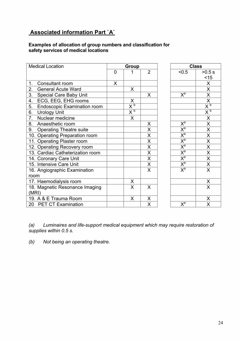
Associated information Part `A` Examples of allocation of group numbers and classification for safety services of medical locations
Group Class Medical Location 0 1 2 <0.5 >0.5 s
<15 1. Consultant room X X 2. General Acute Ward X X 3. Special Care Baby Unit X Xa X 4. ECG, EEG, EHG rooms X X 5. Endoscopic Examination room X b X b 6. Urology Unit X b X b 7. Nuclear medicine X X 8. Anaesthetic room X Xa X 9. Operating Theatre suite X Xa X 10. Operating Preparation room X Xa X 11. Operating Plaster room X Xa X 12. Operating Recovery room X Xa X 13. Cardiac Catheterization room X Xa X 14. Coronary Care Unit X Xa X 15. Intensive Care Unit X Xa X 16. Angiographic Examination room
X Xa X
17. Haemodialysis room X X 18. Magnetic Resonance Imaging (MRI)
X X X
19. A & E Trauma Room X X X 20 PET CT Examination X Xa X (a) Luminaires and life-support medical equipment which may require restoration of supplies within 0.5 s. (b) Not being an operating theatre.
25
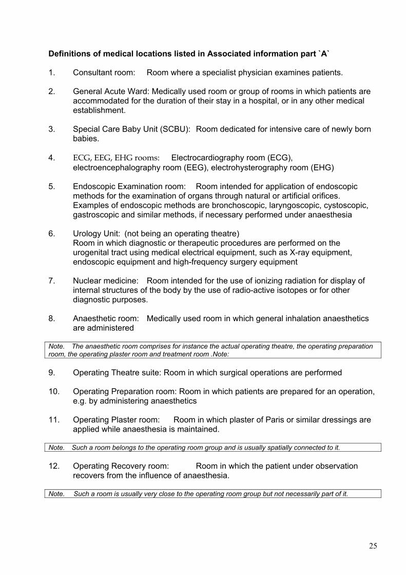
Definitions of medical locations listed in Associated information part `A` 1. Consultant room: Room where a specialist physician examines patients. 2. General Acute Ward: Medically used room or group of rooms in which patients are accommodated for the duration of their stay in a hospital, or in any other medical establishment. 3. Special Care Baby Unit (SCBU): Room dedicated for intensive care of newly born babies. 4. ECG, EEG, EHG rooms: Electrocardiography room (ECG), electroencephalography room (EEG), electrohysterography room (EHG) 5. Endoscopic Examination room: Room intended for application of endoscopic methods for the examination of organs through natural or artificial orifices. Examples of endoscopic methods are bronchoscopic, laryngoscopic, cystoscopic, gastroscopic and similar methods, if necessary performed under anaesthesia 6. Urology Unit: (not being an operating theatre)
Room in which diagnostic or therapeutic procedures are performed on the urogenital tract using medical electrical equipment, such as X-ray equipment, endoscopic equipment and high-frequency surgery equipment
7. Nuclear medicine: Room intended for the use of ionizing radiation for display of
internal structures of the body by the use of radio-active isotopes or for other diagnostic purposes.
8. Anaesthetic room: Medically used room in which general inhalation anaesthetics are administered Note. The anaesthetic room comprises for instance the actual operating theatre, the operating preparation room, the operating plaster room and treatment room .Note: 9. Operating Theatre suite: Room in which surgical operations are performed 10. Operating Preparation room: Room in which patients are prepared for an operation, e.g. by administering anaesthetics 11. Operating Plaster room: Room in which plaster of Paris or similar dressings are applied while anaesthesia is maintained. Note. Such a room belongs to the operating room group and is usually spatially connected to it. 12. Operating Recovery room: Room in which the patient under observation recovers from the influence of anaesthesia. Note. Such a room is usually very close to the operating room group but not necessarily part of it.
26
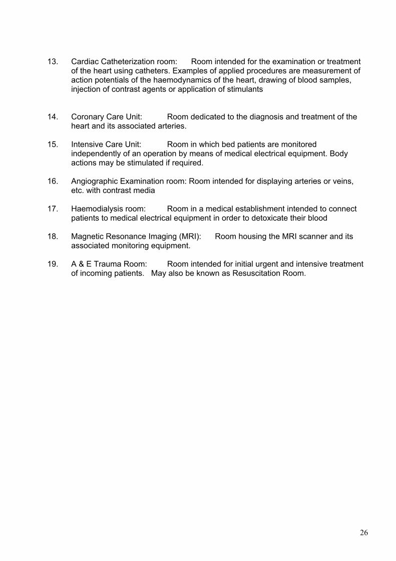
13. Cardiac Catheterization room: Room intended for the examination or treatment of the heart using catheters. Examples of applied procedures are measurement of action potentials of the haemodynamics of the heart, drawing of blood samples, injection of contrast agents or application of stimulants 14. Coronary Care Unit: Room dedicated to the diagnosis and treatment of the heart and its associated arteries. 15. Intensive Care Unit: Room in which bed patients are monitored independently of an operation by means of medical electrical equipment. Body actions may be stimulated if required. 16. Angiographic Examination room: Room intended for displaying arteries or veins, etc. with contrast media 17. Haemodialysis room: Room in a medical establishment intended to connect patients to medical electrical equipment in order to detoxicate their blood 18. Magnetic Resonance Imaging (MRI): Room housing the MRI scanner and its associated monitoring equipment. 19. A & E Trauma Room: Room intended for initial urgent and intensive treatment
of incoming patients. May also be known as Resuscitation Room.
27
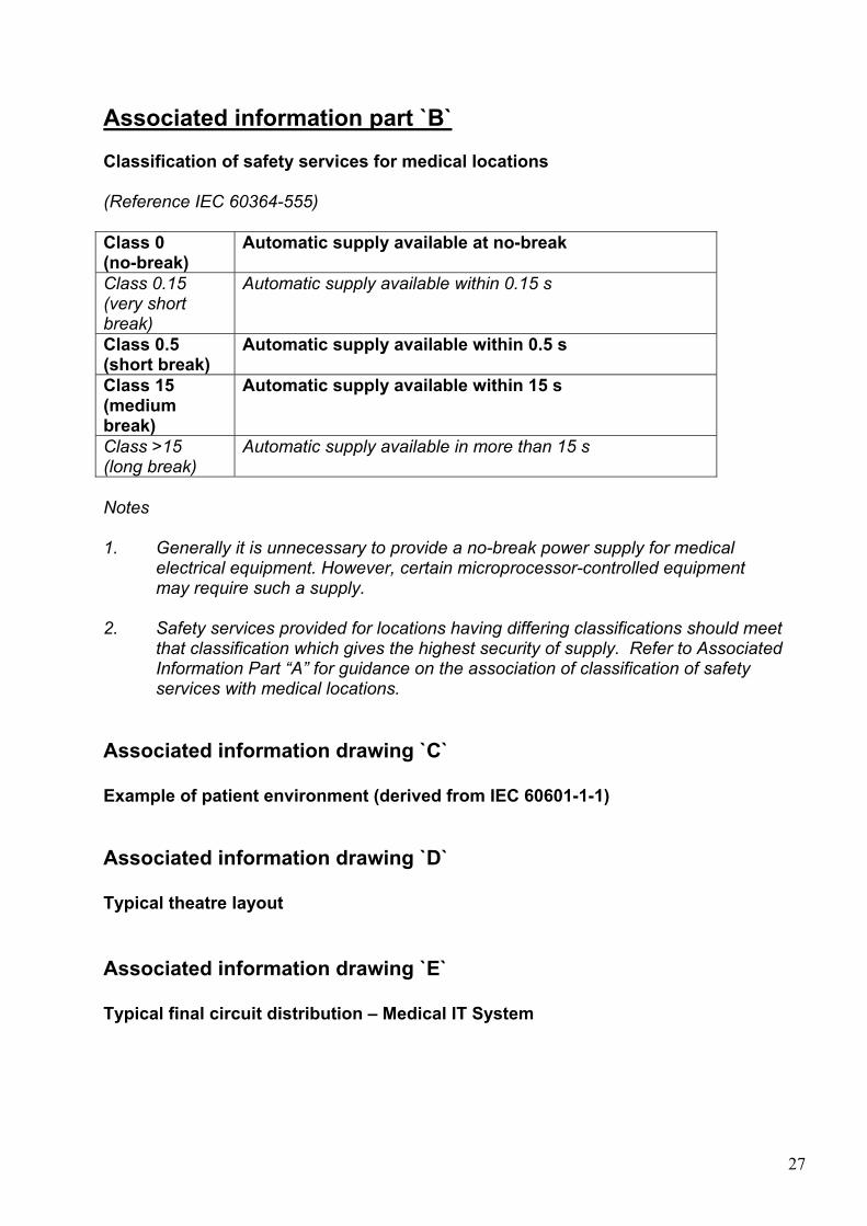
Associated information part `B` Classification of safety services for medical locations (Reference IEC 60364-555) Class 0 (no-break)
Automatic supply available at no-break
Class 0.15 (very short break)
Automatic supply available within 0.15 s
Class 0.5 (short break)
Automatic supply available within 0.5 s
Class 15 (medium break)
Automatic supply available within 15 s
Class >15 (long break)
Automatic supply available in more than 15 s
Notes 1. Generally it is unnecessary to provide a no-break power supply for medical electrical equipment. However, certain microprocessor-controlled equipment may require such a supply. 2. Safety services provided for locations having differing classifications should meet
that classification which gives the highest security of supply. Refer to Associated Information Part “A” for guidance on the association of classification of safety services with medical locations.
Associated information drawing `C` Example of patient environment (derived from IEC 60601-1-1) Associated information drawing `D` Typical theatre layout Associated information drawing `E` Typical final circuit distribution – Medical IT System
28
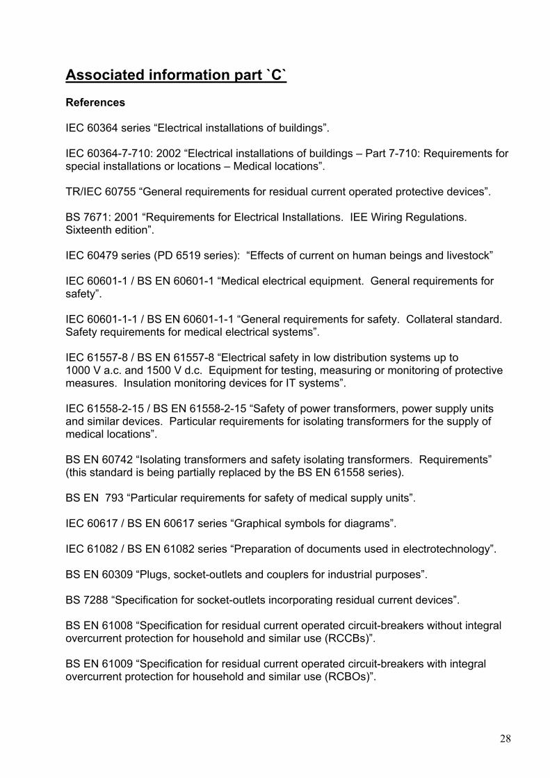
Associated information part `C` References IEC 60364 series “Electrical installations of buildings”. IEC 60364-7-710: 2002 “Electrical installations of buildings – Part 7-710: Requirements for special installations or locations – Medical locations”. TR/IEC 60755 “General requirements for residual current operated protective devices”. BS 7671: 2001 “Requirements for Electrical Installations. IEE Wiring Regulations. Sixteenth edition”. IEC 60479 series (PD 6519 series): “Effects of current on human beings and livestock” IEC 60601-1 / BS EN 60601-1 “Medical electrical equipment. General requirements for safety”. IEC 60601-1-1 / BS EN 60601-1-1 “General requirements for safety. Collateral standard. Safety requirements for medical electrical systems”. IEC 61557-8 / BS EN 61557-8 “Electrical safety in low distribution systems up to 1000 V a.c. and 1500 V d.c. Equipment for testing, measuring or monitoring of protective measures. Insulation monitoring devices for IT systems”. IEC 61558-2-15 / BS EN 61558-2-15 “Safety of power transformers, power supply units and similar devices. Particular requirements for isolating transformers for the supply of medical locations”. BS EN 60742 “Isolating transformers and safety isolating transformers. Requirements” (this standard is being partially replaced by the BS EN 61558 series). BS EN 793 “Particular requirements for safety of medical supply units”. IEC 60617 / BS EN 60617 series “Graphical symbols for diagrams”. IEC 61082 / BS EN 61082 series “Preparation of documents used in electrotechnology”. BS EN 60309 “Plugs, socket-outlets and couplers for industrial purposes”. BS 7288 “Specification for socket-outlets incorporating residual current devices”. BS EN 61008 “Specification for residual current operated circuit-breakers without integral overcurrent protection for household and similar use (RCCBs)”. BS EN 61009 “Specification for residual current operated circuit-breakers with integral overcurrent protection for household and similar use (RCBOs)”.
29
BS 764 “Specification for automatic change-over contactors for emergency lighting systems”. BS EN 60947 “Specification for low-voltage switchgear and controlgear”. BS EN 60529 “Specification for degrees of protection provided by enclosures (IP code)”. BS EN 60439 “Specification for low-voltage switchgear and controlgear assemblies”. BS 88 “Cartridge fuses for voltages up to and including 1000 V a.c. and 1500 d.c.”. BS 1363 “13 A plugs, socket-outlets, connection units and adaptors. BS EN 50091 “Specification for uniterruptible power systems (UPS)”. BS EN 62040 –3 “Uniterruptible power systems (UPS). Methods of specifying the performance and test requirements ”. BS 5266 “Emergency lighting”. BS 5499 “Graphic symbols and signs. Safety signs, including fire safety signs”. BS EN 60623 “Vented nickel-cadmium prismatic rechargeable single cells”. BS EN 60896 “Stationary lead-acid batteries. General requirements and methods of testing”. BS 5514 “Reciprocating internal combustion engines. Performance”. BS 4999 “General requirements for rotating electrical machines”. BS 5000 “Rotating electrical machines of particular types or for particular applications”. Protective measures with insulation monitoring (2nd edition) – Wolgang Hofheinz Isolated power – The answer to system security (Stephen J. Kay). Safety of Electrical Installations up to 1000 V (Wilhelm Rudolph).
30
31