Computer Networks: Wireless Networks Ivan Marsic Rutgers University Chapter 6 – Wireless Networks.
International Journal of Wireless & Mobile Networks (IJWMN) Vol. 3, No. 2, April 2011
DOI : 10.5121/ijwmn.2011.3201 1
OPTIMIZED PERFORMANCE EVALUATION OF LTE
HARD HANDOVER ALGORITHM WITH AVERAGE
RSRP CONSTRAINT
1Cheng-Chung Lin,
2Kumbesan Sandrasegaran,
3Huda Adibah Mohd Ramli, and
4Riyaj Basukala
1,2,3,4 Faculty of Engineering and Information Technology, University of Technology,
Sydney, Australia
[1Cheng-Chung.Lin,
2kumbes,
3HudaAdibah.MohdRamli]@eng.uts.edu.au
ABSTRACT
Hard handover mechanism is adopted to be used in 3GPP Long Term Evolution (3GPP LTE) in order to
reduce the complexity of the LTE network architecture. This mechanism comes with degradation in
system throughput as well as a higher system delay. This paper proposes a new handover algorithm
known as LTE Hard Handover Algorithm with Average Received Signal Reference Power (RSRP)
Constraint (LHHAARC) in order to minimize number of handovers and the system delay as well as
maximize the system throughput. An optimized system performance of the LHHAARC is evaluated and
compared with three well-known handover algorithms via computer simulation. The simulation results
show that the LHHAARC outperforms three well-known handover algorithms by having less number of
average handovers per UE per second, shorter total system delay whilst maintaining a higher total
system throughput.
KEYWORDS
Performance, Handover, Handover algorithm, Optimization, LTE
1. INTRODUCTION
3GPP LTE is a new radio access technology proposed to provide a smooth migration towards
Fourth Generation (4G) network [1]. It is designed to increase the capacity, coverage, and speed
as compared to the earlier wireless systems [2, 3]. LTE uses Orthogonal Frequency Division
Multiple Access (OFDMA), which is a variant of OFDM (Orthogonal Frequency Division
Multiplexing), as its access technology in the downlink [4] while single-carrier frequency-
division multiple access (SC-FDMA) is the uplink multiple access scheme [5]. OFDMA is a
multi-carrier access technology that divides the wide available bandwidth into multiple equally
spaced and mutually orthogonal sub-carriers [6]. The smallest transmission unit in the downlink
LTE system is known as a Resource Block (RB) that contains 12 sub-carriers (180 kHz total
bandwidth) of 1 ms duration [7].
The LTE network architecture consists of three elements: evolved-NodeB (eNodeB), Mobile
Management Entity (MME), and Serving Gateway (S-GW) / Packet Data Network Gateway (P-
GW). eNodeB performs all radio interface-related functions such as packet scheduling and
handover. MME manages mobility, user equipment (UE) identity, and security parameters. S-
GW and P-GW are the nodes that terminate the interface towards eUTRAN and Packet Data
Network, respectively. There are two interfaces concerned in handovers in eUTRAN which are
S1 and X2 interfaces. Both interfaces can be used in handover procedures, but with different
purposes. More details about the handover procedures on S1 and X2 interfaces are discussed
later.
International Journal of Wireless & Mobile Networks (IJWMN) Vol. 3, No. 2, April 2011
2
Handover in LTE is purely hard handover (both S1 and X2 interface handover). The use of hard
handover reduces the complexity of the LTE network architecture. However, the hard handover
may result inefficient LTE performance (i.e. increasing number of handovers, decreasing system
throughput as well as increasing system delay). Therefore, an efficient handover algorithm that
can minimize the number of handovers and system delay as well as maximize the system
throughput is needed.
A handover algorithm is used for making a handover decision. A handover will be triggered if
several conditions specified by a handover algorithm are satisfied. Due to the user’s mobility,
the conditions of a handover algorithm could vary over time. Therefore it is necessary to
determine optimized parameters to ensure efficiency and reliability of a handover algorithm.
A new handover algorithm known as LTE Hard Handover Algorithm with Average RSRP
Constraint (LHHAARC) that can efficiently reduce the number of handovers, minimizing the
total system delay and maximizing the total system throughput is proposed in this paper. The
LHHAARC algorithm is evaluated and compared with three well known handover algorithms
using optimized handover parameters under three different speed (3, 30, 120 km/hr) scenarios.
The rest of this paper is organized as follows: Section 2 reviews on the related handover studies
followed by detailed descriptions of the well-known and proposed handover algorithms in
Section 3. The metrics used for performance evaluation and simulation environment are
discussed in Section 4 and Section 5 respectively. Section 6 contains results of the optimization
and performance evaluation and conclusions are summarized in Section 7.
2. HANDOVER TECHNIQUES
Handover refers to the transfer of a user’s connection from one radio channel to another (can be
the same or different cell) [8]. Handover can be categorized as hard handover [9] and soft
handover [10] also known as Break-Before-Connect (BBC) and Connect (Entry)-Before-Break
(CBB), respectively. Soft and hard handover followed by handover in LTE are discussed in the
following subsections.
2.1. Soft Handover – Connect-Before-Break Handover
Soft handover is a category of handover procedures where the radio links are added and
abandoned in such manner that the UE always keeps at least one radio link to the UTRAN [8].
Soft and softer handover were introduced in WCDMA architecture. There is a centralized
controller called Radio Network Controller (RNC) to perform handover control for each UE in
the architecture of WCDMA. It is possible for a UE to simultaneously connect to two or more
cells (or cell sectors) during a call [11]. If the cells the UE connected are from the same physical
site, it is referred as softer handover. In handover aspect, soft handover is suitable for
maintaining an active session, preventing voice call dropping, and resetting a packet session.
However, the soft handover requires much more complicated signalling, procedures and system
architecture such as in the WCDMA network.
2.2. Hard Handover – Break-Before-Connect Handover
Hard handover is a category of handover procedures where all the old radio links in the UE are
abandoned before the new radio links are established [8]. The hard handover is commonly used
when dealing with handovers in the legacy wireless systems. The hard handover requires a user
to break the existing connection with the current cell (source cell) and make a new connection to
the target cell.
2.3. Handover in LTE
There are two types of handover procedure in downlink LTE for UEs in active mode (Active
mode means the UE is transmitting/receiving packets to/from the core network, either voice
International Journal of Wireless & Mobile Networks (IJWMN) Vol. 3, No. 2, April 2011
3
packet, or data packet.) which are the S1 and X2 handover procedures. The X2-handover
procedure is normally used for the inter-eNodeB handover to balance network load and prevent
interference. However, when there is no X2 interface between two eNodeBs, or if the source
eNodeB has been configured to perform handover towards a particular target eNodeB via the S1
interface, then an S1-handover procedure will be triggered [12]. The S1-based handover
procedure is used for communicating with non-3GPP specific access technologies such as
CDMA2000/HRPD [13]. There are three phases involved in both S1 and X2 handover
procedures which are preparation phase, execution phase, and completion phase [14, 15]. In the
preparation phase, the UE needs to send measurement reports periodically to the source eNodeB
[16]. Based on these reports, the source eNodeB will decide to which target eNodeB the UE
should be handed over. Besides the measurement reports, other criteria are also considered by
the source eNodeB before a control message is sent to the target eNodeB to prepare for the
handover. Upon receiving the control message requesting to prepare for handover, the target
eNodeB will prepare a buffer for the UE.
Once the preparation phase is completed, a handover command control message is sent by the
source eNodeB to the UE in the execution phase to notify the UE that it is going to be handed
over to another eNodeB. Upon receiving the message, the UE will disconnect itself from the
source eNodeB and request for connection with the target eNodeB. At the same time, the source
eNodeB forwards all packets of the UE to the target eNodeB. These packets are queued by the
target eNodeB in the UE buffer. Once the UE has successfully connected to the target eNodeB,
the target eNodeB transmits all the buffered packets of the UE followed by the incoming
packets from the target gateway. The handover procedure moves to the completion phase after
the UE sends to the target eNodeB a handover complete message that indicates this handover is
completed.
The main purposes of the completion phase are to release all the resources used by the UE at the
source eNodeB and to notify the upper layer to switch the path of the packet to the target
eNodeB. Therefore, the target eNodeB needs to inform the source eNodeB to release all
resources from the UE and the target MME to execute path switching to the target eNodeB,
respectively.
3. HANDOVER ALGORITHMS
Three well known handover algorithms followed by the proposed algorithm in LTE system are
discussed in this section.
3.1. LTE Hard Handover Algorithm
The LTE Hard Handover Algorithm, also known as “Power Budget Handover Algorithm”, is a
basic but effective handover algorithm consisting of two variables, handover margin (HOM)
and Time to Trigger (TTT) timer [17]. A handover margin is a constant variable that represents
the threshold of the difference in received signal strength between the serving and the target
cells. HOM ensures the target cell is the most appropriate cell the mobile camps on during
handover. A TTT value is the time interval that is required for satisfying HOM condition. Both
HOM and TTT are used for reducing unnecessary handovers which is called “Ping-Pong
effect”. When a mobile is experiencing this effect, it is handed over from a serving cell to a
target cell and handed back to original serving cell again in a small period of time [18]. This
effect increases the required signaling resources, decreases system throughput, and increases
data traffic delay caused by buffering the incoming traffic at the target cell when each handover
occurs. Therefore effectively preventing unnecessary handovers is essential. TTT restricts the
handover action from being triggered within certain time duration. A handover action can only
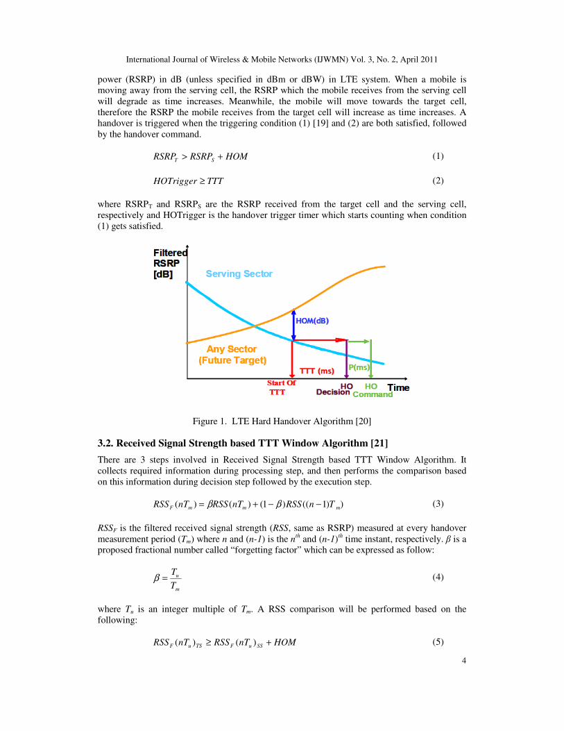
be performed after the TTT condition has been satisfied. Figure 1 shows the basic concept of
LTE hard handover algorithm. The received signal strength is called reference signal received
International Journal of Wireless & Mobile Networks (IJWMN) Vol. 3, No. 2, April 2011
4
power (RSRP) in dB (unless specified in dBm or dBW) in LTE system. When a mobile is
moving away from the serving cell, the RSRP which the mobile receives from the serving cell
will degrade as time increases. Meanwhile, the mobile will move towards the target cell,
therefore the RSRP the mobile receives from the target cell will increase as time increases. A
handover is triggered when the triggering condition (1) [19] and (2) are both satisfied, followed
by the handover command.
HOMRSRPRSRP ST +> (1)
TTTHOTrigger ≥ (2)
where RSRPT and RSRPS are the RSRP received from the target cell and the serving cell,
respectively and HOTrigger is the handover trigger timer which starts counting when condition
(1) gets satisfied.
Figure 1. LTE Hard Handover Algorithm [20]
3.2. Received Signal Strength based TTT Window Algorithm [21]
There are 3 steps involved in Received Signal Strength based TTT Window Algorithm. It
collects required information during processing step, and then performs the comparison based
on this information during decision step followed by the execution step.
))1(()1()()( mmmF TnRSSnTRSSnTRSS −−+= ββ (3)
RSSF is the filtered received signal strength (RSS, same as RSRP) measured at every handover
measurement period (Tm) where n and (n-1) is the nth
and (n-1)th time instant, respectively. β is a
proposed fractional number called “forgetting factor” which can be expressed as follow:
m
u
T
T=β (4)
where Tu is an integer multiple of Tm. A RSS comparison will be performed based on the
following:
HOMnTRSSnTRSS SSuFTSuF +≥ )()( (5)
International Journal of Wireless & Mobile Networks (IJWMN) Vol. 3, No. 2, April 2011
5
HOM is a constant threshold value, RSSF(nTu)TS and RSSF(nTu)SS are the filtered RSS of the target sector (TS) and the filtered RSS of the serving sector (SS) at (n Tu)
th interval, respectively.
This algorithm tracks the RSS value from each eNodeB and stores the instantaneous RSS value.
Filtered RSS value at each instant is calculated using historical data (previously filtered RSS) by applying the forgetting factor variable. The closer the forgetting factor gets to 0, the higher the
proportion that the current RSS depends on the filtered RSS in previous time instant. On the
other hand, the closer the forgetting factor gets to 1, the higher the proportion that the current
filtered RSS depends on the current RSS value. A handover decision will be made after (4) is
satisfied for duration of whole Tu window.
3.3. Integrator Handover Algorithm [17]
Integrator Handover Algorithm is a LTE handover algorithm proposed in 2008. The main
concept is to make the handover decision by the historical signal strength differences. The idea
of historical data is similar to what Received Signal Strength based TTT Window Algorithm
has. There are 3 parts in integrator handover algorithm, RSRP difference calculation, filtered RSRP difference computation, and handover decision. The RSRP difference calculation is
presented as following:
)()()(_ tRSRPtRSRPtDIF STjs −= (6)
where RSRPT(t) and RSRPS(t) represent the RSRP received from the target cell and serving cell
at time t, respectively. DIFs_j(t) is the RSRP difference of the user j at serving cell s at time t. The filtered RSRP difference computation can be written as following:
)()1()1()( ___ tDIFtFDIFtFDIF jsjsjs αα +−−= (7)
where α is a proposed variable with constraint 0 ≤ α ≤ 1. FDIFs_j(t) is the filtered RSRP
difference value of user j at serving cell s at time t, and DIFs_j(t) is the RSRP difference value
calculated in (6). A filtered RSRP difference value will depend on the proportion between
current RSRP difference and historical filtered RSRP difference in previous time instant by
changing the α variable. The closer the α goes to 1, the higher the chance that filtered RSRP
difference will have a heavier portion on the current RSRP difference calculated by (6). In the
other way, the closer the α goes 0, the filtered RSRP difference will have a heavier portion on
the previous historical filtered RSRP difference then on the current RSRP difference. Once the
filtered difference has been computed, the handover decision will be made if the following condition is satisfied:
oldFDIFThreshtFDIF js >)(_ (8)
FDIFThreshold is a constant value equivalent to HOM. If the filtered RSRP difference between
any of target cell and serving cell is greater than this threshold, the handover decision will be
triggered immediately. Please note ping-pong effect may occur due to lack of TTT mechanism
involved in this algorithm.
3.4. LTE Hard Handover Algorithm with Average RSRP Constraint
LTE Hard Handover Algorithm with Average RSRP Constraint is proposed based on LTE Hard
Handover Algorithm with an extra average RSRP condition for more efficient handover performance. The average RSRP can be calculated as following:
International Journal of Wireless & Mobile Networks (IJWMN) Vol. 3, No. 2, April 2011
6
N
nTRSRP
RSRP
N
1n
mjs
javgS
∑==
)(_
_ (9)
where RSRPS_j(nTm) is the RSRP received by user j from serving cell S at n-th handover
measurement period of Tm and N is the total number of periods of duration Tm. An average
RSRP of cell S received by user j (RSRPavgS_j) can be calculated by a sum of each n-th handover measurement period (Tm) up to N divided by N times. An average RSRP constraint can be
expressed as following:
jSavgT RSRPtRSRP_
)( > (10)
where RSRPT(t) is the current RSRP received from target cell T and RSRPavgS_j is the average
RSRP computed from equation (9). The handover decision will be made by satisfying equation
(10) followed by the same conditions as in LTE Hard Handover Algorithm listed below:
HOMRSRPRSRP ST +> (11)
TTTHOTrigger ≥ (12)
A handover will be triggered if and only if equation (10), (11), and (12) are all satisfied. Please note RSRPavgS_j will be reset to 0 each time due to serving cell changes when a handover is
successfully performed.
The concept of this algorithm is to narrow down the possibility of handovers to minimize unnecessary handovers and ensure the channel quality of the target cell a user can have is not
only higher than the current RSRP of serving cell with a certain threshold, but also better than
the average RSRP received from the serving cell from the first handover measurement period till the last.
4. PERFORMANCE METRICS
The system performance of the four handover algorithms is evaluated on the basis of average
handovers per UE per second, total system throughput, and total system delay. The average
handovers per UE per second is the metric that is related to handover aspect whereas the system
throughput and delay are network related performance metrics. Detailed descriptions of each
metric are provided as below:
The average handovers per UE per second represents the number of handovers occurs during a
simulation. It has the following expression:
TJ
HOHO Total
avg×
= (13)
where HOavg and HOTotal are the average handovers per UE per second and total number of
successful handovers, respectively and J and T are the total number of users and total simulation
time, respectively. HOTotal is incremented if and only if a handover is performed successfully. A
successful handover is defined as a user has been handed over from source to target cell while
maintaining the on-going data transmission. The cell throughput is defined as the total number
of bits correctly received by all users per second. The cell throughput is measured at the eNodeB. It is mathematically expressed as:
∑∑= =
=J
1j
T
1t
j ttputT
1throughputcell )( (14)

International Journal of Wireless & Mobile Networks (IJWMN) Vol. 3, No. 2, April 2011
7
where tputj(t) is the total size of correctly received packets (in bits) of user j at time interval t, T is the total simulation time and J is the total number of users. The total system throughput is the
sum of the 7 cells throughput expressed below:
∑=
=C
1c
cTotal throughputcellthroughput (15)
where cell throughputc is the individual cell throughput of cell c calculated from equation (14) and C is the total cells in the simulation. System delay is defined as average system Head-of-
Line (HOL) delay or queuing delay. A HOL delay is defined as the time duration from the HOL
packet’s arrival time at the eNodeB buffer to current time. It can be expressed in the following equation:
∑∑==
=J
1j
j
T
1t
tWJ
1
T
1DelayCell )( (16)
where J is the total number of users within the cell, T represents the total simulation time, and
Wj(t) denotes the HOL delay of user j at time t. The total system delay is the sum of the 7 cells
delay expressed below:
∑=
=C
1c
cTotal DelayPacketDelayPacket (17)
where Packet Delayc is the individual cell throughput of cell c calculated from equation (16) and
C is the total cells in the simulation.
5. SIMULATION ENVIRONMENT AND DESCRIPTIONS
The performance of four handover algorithms previously discussed are evaluated, optimized and
compared using a C++ platform computer simulation which simulates the downlink LTE system consisting of a 7-hexagonal-cell scenario of 5 MHz bandwidth with 25 RBs and 2 GHz carrier
frequency based on [22, 23] containing 100 users. Users are uniformly distributed within the
rectangle area as shown in Figure 2.
Figure 2. Simulation Environment

International Journal of Wireless & Mobile Networks (IJWMN) Vol. 3, No. 2, April 2011
8
Each eNodeB is located at the centre of each cell with 100m radius and it is assumed that equal transmit power (43.01 dBm total eNodeB transmit power) is used on each RB. Each UE is
constantly moving at a fixed speed and the speed is varied under three different scenarios (i.e. 3
km/hr, 30 km/hr or 120 km/hr scenarios). Direction of each UE is randomly chosen between 0 to 2π, initially and stays constant in throughout its session.
Users are wrapped around whenever they reach the red rectangle edge. [24]. The Cost-231
HATA model for an urban environment [25, 26] is used to compute pathloss. A Gaussian log-
normal distribution with 0 mean and 8 dB standard deviation [27] is used for modelling shadow
fading. A Non-frequency selective Rayleigh fading [28] is used to model the radio propagation
channel. A user that has data to receive estimates its instantaneous Signal-to-Interference-Noise-
Ratio (SINR) on each RB, converts it into a CQI value with the target block error rate (BLER)
to be less than 10 % [7] and reports each CQI value to the source eNodeB. It is assumed in this
paper that the CQI reporting is performed in each TTI of 1 millisecond and on each RB. A total of 16 Channel Quality Information (CQI) levels as defined in [7] are used. The equations for
generating BLER curves in [29] are used for modeling the performance of turbo codes in
Rayleigh fading channel. The Hybrid Automatic Repeat Request (HARQ) technique in [30] is adopted to recover wireless transmission errors. The CQI and HARQ reporting are modeled
error free with 3 ms CQI delay and 4 ms HARQ (ACK/NACK) delay. The maximum number of
retransmissions is limited to 3. Round-Robin packet scheduler is chosen for a fair transmission opportunity for all users and a 50 milliseconds interval is set for each user’s measurement report
for handover decision. A shorter simulation time of 1000 and longer simulation time of 10000
milliseconds are used for performance optimization and handover algorithms performance
comparison, respectively. System parameters used in the simulation are given in Table 1.
Table 1. Simulation Parameters
Parameters Values
Cellular layout Hexagonal grid, wrap around (reflect), 7 cells
Carrier Frequency 2 GHz
Bandwidth 5 MHz
Number of RBs 25
Number of sub-carriers per RB
12
Sub-carrier Spacing 15 kHz
Path Loss Cost 231 Hata model
Shadow fading Gaussian log-normal distribution
Multi-path Non-frequency selective Rayleigh fading
Packet Scheduler Round Robin
Scheduling Time (TTI)
1 ms
Data Traffic 1 Mbps Constant Rate
User 100
User’s position Uniform distributed
User’s direction Randomly choose from [0,2π], constantly at all time
Simulation time 1000 ms for optimization
10000 ms for performance evaluation
RSRP sampling timer interval
50 ms
The optimization parameters are determined by comparing the new so-called OptimizeRatio
value which is a ratio calculated by total system throughput over the average number of
handovers. OptimizeRatio can be computed as following:
International Journal of Wireless & Mobile Networks (IJWMN) Vol. 3, No. 2, April 2011
9
),(
),(
),(
TTTHOM
TTTHOM
SpeedHOAANOH
STtioOptimizeRa = (18)
where HOA indicates the handover algorithm, Speed is the corresponding speed in each
scenario. ST and ANOH are the total system throughput of sum of 7 cells and the average
number of handover per UE per second, respectively. TTT will be replaced by α or β factor
when Integrator Handover Algorithm or Received Signal Strength based TTT Window
Algorithm is selected.
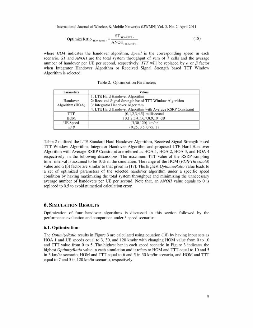
Table 2. Optimization Parameters
Parameters Values
Handover Algorithm (HOA)
1: LTE Hard Handover Algorithm 2: Received Signal Strength based TTT Window Algorithm 3: Integrator Handover Algorithm 4: LTE Hard Handover Algorithm with Average RSRP Constraint
TTT {0,1,2,3,4,5} millisecond
HOM {0,1,2,3,4,5,6,7,8,9,10} dB
UE Speed {3,30,120} km/hr
α / β {0.25, 0.5, 0.75, 1}
Table 2 outlined the LTE Standard Hard Handover Algorithm, Received Signal Strength based
TTT Window Algorithm, Integrator Handover Algorithm and proposed LTE Hard Handover
Algorithm with Average RSRP Constraint are referred as HOA 1, HOA 2, HOA 3, and HOA 4 respectively, in the following discussions. The maximum TTT value of the RSRP sampling
timer interval is assumed to be 10% in the simulation. The range of the HOM (FDIFThreshold)
value and α (β) factor are similar to that given in [17]. The highest OptimizeRatio value leads to
a set of optimized parameters of the selected handover algorithm under a specific speed
condition by having maximizing the total system throughput and minimizing the unnecessary
average number of handovers per UE per second. Note that, an ANOH value equals to 0 is
replaced to 0.5 to avoid numerical calculation error.
6. SIMULATION RESULTS
Optimization of four handover algorithms is discussed in this section followed by the
performance evaluation and comparison under 3 speed scenarios.
6.1. Optimization
The OptimizeRatio results in Figure 3 are calculated using equation (18) by having input sets as
HOA 1 and UE speeds equal to 3, 30, and 120 km/hr with changing HOM value from 0 to 10
and TTT value from 0 to 5. The highest bar in each speed scenario in Figure 3 indicates the
highest OptimizeRatio value in each simulation and it refers to HOM and TTT equal to 10 and 5
in 3 km/hr scenario, HOM and TTT equal to 6 and 5 in 30 km/hr scenario, and HOM and TTT
equal to 7 and 5 in 120 km/hr scenario, respectively.

International Journal of Wireless & Mobile Networks (IJWMN) Vol. 3, No. 2, April 2011
10
Figure 3. OptimizeRatio in HOA 1
Figure 4. OptimizeRatio in HOA 2
Figure 4 demonstrates the OptimizeRatio in HOA 2 with 3 speed scenarios. The highest
OptimizeRatio value in 3 km/hr scenario, 30 km/hr scenario, and 120 km/hr scenario, are β and
HOM equal 0.25 and 6, β and HOM equal 1 and 6, and β and HOM equal to 0.25 and 9,
respectively.
International Journal of Wireless & Mobile Networks (IJWMN) Vol. 3, No. 2, April 2011
11
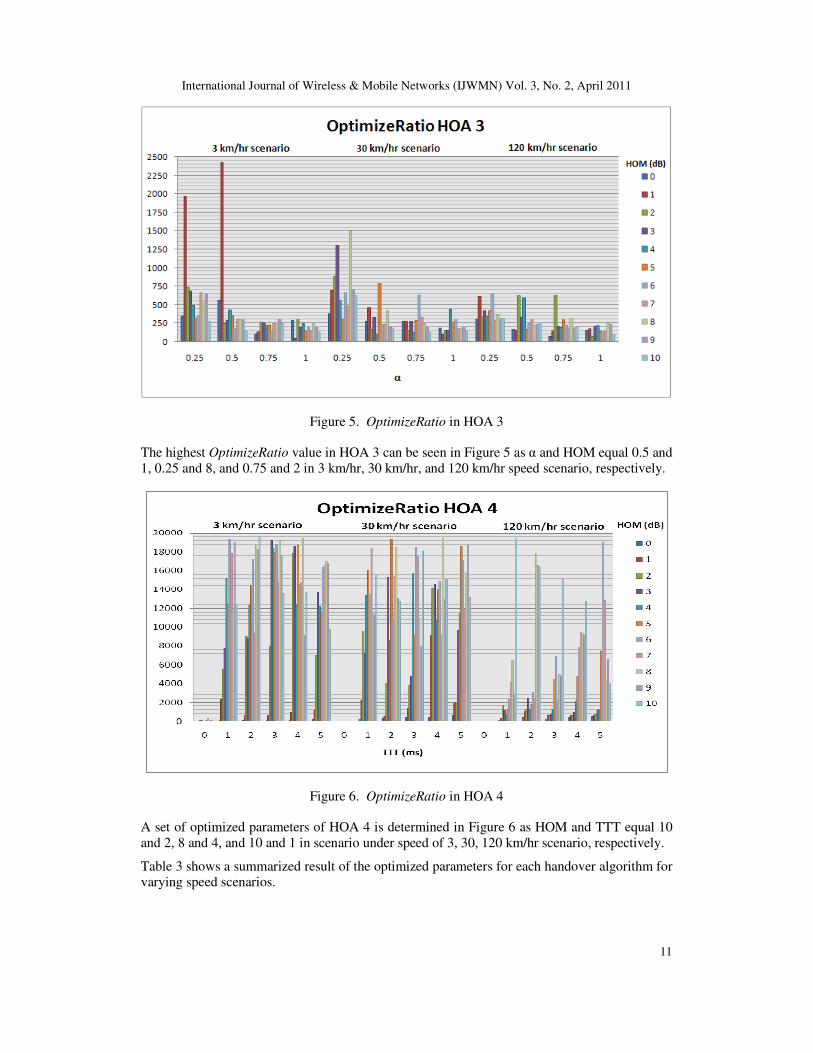
Figure 5. OptimizeRatio in HOA 3
The highest OptimizeRatio value in HOA 3 can be seen in Figure 5 as α and HOM equal 0.5 and
1, 0.25 and 8, and 0.75 and 2 in 3 km/hr, 30 km/hr, and 120 km/hr speed scenario, respectively.
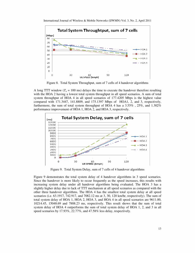
Figure 6. OptimizeRatio in HOA 4
A set of optimized parameters of HOA 4 is determined in Figure 6 as HOM and TTT equal 10
and 2, 8 and 4, and 10 and 1 in scenario under speed of 3, 30, 120 km/hr scenario, respectively.
Table 3 shows a summarized result of the optimized parameters for each handover algorithm for varying speed scenarios.

International Journal of Wireless & Mobile Networks (IJWMN) Vol. 3, No. 2, April 2011
12
Speed [km/hr] HOA 1 HOA 2 HOA 3 HOA 4
3 [HOM, TTT] = [10, 5]
[HOM, β] = [6, 0.25] [HOM, α] = [1, 0.5] [HOM, TTT] = [10, 2]
30 [HOM, TTT] = [6, 5]
[HOM, β] = [6, 1] [HOM, α] = [8, 0.25] [HOM, TTT] = [8, 4]
120 [HOM, TTT] = [7, 5]
[HOM, β] = [9, 0.25] [HOM, α] = [6, 0.25] [HOM, TTT] = [10, 1]
The remaining results of the performance comparisons are based on the optimized parameters as
listed in Table 3.
6.2. Performance Evaluation and Comparison
Figure 7. Average Number of Handovers per UE per Second of 4 handover algorithms
Figure 7 shows the average number of HOs per UE per second under the four handover
algorithms with increasing UE speeds. Since the HOA 3 does not implement TTT mechanism, it
can be seen in the figure that, with increasing UE speeds, the average number of handovers per
UE per second under the HOA 3 is significantly higher as compared with all the other three
handover algorithms. All three handover algorithms (i.e. HOA 1, HOA 2, and HOA 4) achieve a
similar average number of handovers per UE per second at a lower user speed whereas almost
comparable average number of handovers per UE per second achieve under the HOA 2 and HOA 4 respectively at a higher UE speed. The result shows that the HOA 4 has a sum of
average number of handovers per UE per second of 3 speed scenarios as 1.49 which is less than
1.68, 1.54, and 4.19 of HOA 1, HOA 2, and HOA 3, respectively. Furthermore, the sum of average number of handovers per UE per second in proposed HOA 4 is effectively reduced up
to 35.56% when compared with the HOA 3.
Figure 8 shows the total system throughput of 7 cells under 4 handover algorithms with increasing UE speeds. A higher total system throughput value implies a higher system
performance a handover algorithm offers. The figure demonstrates that HOA 3 has a highest
total system throughput as 77.2496 Mbps at 3 km/hr due to users frequently handover for cells
which have better channel quality at low speed but the total system throughput drops gradually
to 55.9141 and 41.976 Mbps at speed 30 and 120 km/hr respectively, due to increase in number
of handovers resulting in network congestion and therefore the drop in system performance.
Table 3. Optimized Parameters
International Journal of Wireless & Mobile Networks (IJWMN) Vol. 3, No. 2, April 2011
13
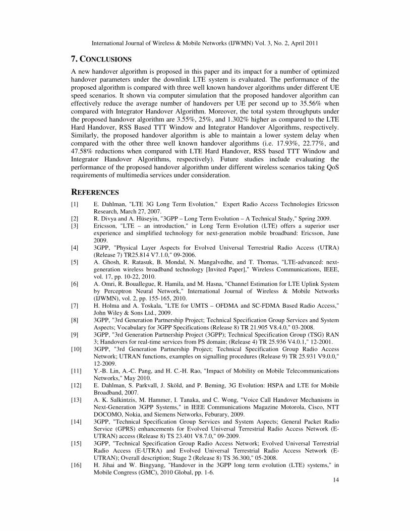
Figure 8. Total System Throughput, sum of 7 cells of 4 handover algorithms
A long TTT window (Tu = 100 ms) delays the time to execute the handover therefore resulting
with the HOA 2 having a lowest total system throughput in all speed scenarios. A sum of total system throughput of HOA 4 in all speed scenarios of 177.4205 Mbps is the highest value
compared with 171.3447, 141.8809, and 175.1397 Mbps of HOA1, 2, and 3, respectively,
furthermore, the sum of total system throughput of HOA 4 has a 3.55% , 25%, and 1.302%
performance improvement of HOA 1, HOA 2, and HOA 3, respectively.
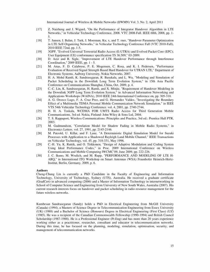
Figure 9. Total System Delay, sum of 7 cells of 4 handover algorithms
Figure 9 demonstrates the total system delay of 4 handover algorithms in 3 speed scenarios.
Since the handover is more likely to occur frequently as the speed increases, this results with increasing system delay under all handover algorithms being evaluated. The HOA 3 has a
slightly higher delay due to lack of TTT mechanism at all speed scenarios as compared with the
other three handover algorithms. The HOA 4 has the smallest total system delay at all speed
scenarios (i.e. 63.1917, 742.917, and 7082.12 ms at 3, 30, 120 km/hr, respectively). The sum of
total system delay of HOA 1, HOA 2, HOA 3, and HOA 4 in all speed scenarios are 9611.00,
10214.45, 15048.69 and 7888.23 ms, respectively. This result shows that the sum of total
system delay of HOA 4 outperforms the sum of total system delay of HOA 1, 2, and 3 in all
speed scenarios by 17.93%, 22.77%, and 47.58% less delay, respectively.
International Journal of Wireless & Mobile Networks (IJWMN) Vol. 3, No. 2, April 2011
14
7. CONCLUSIONS
A new handover algorithm is proposed in this paper and its impact for a number of optimized
handover parameters under the downlink LTE system is evaluated. The performance of the
proposed algorithm is compared with three well known handover algorithms under different UE
speed scenarios. It shown via computer simulation that the proposed handover algorithm can
effectively reduce the average number of handovers per UE per second up to 35.56% when
compared with Integrator Handover Algorithm. Moreover, the total system throughputs under
the proposed handover algorithm are 3.55%, 25%, and 1.302% higher as compared to the LTE
Hard Handover, RSS Based TTT Window and Integrator Handover Algorithms, respectively.
Similarly, the proposed handover algorithm is able to maintain a lower system delay when
compared with the other three well known handover algorithms (i.e. 17.93%, 22.77%, and 47.58% reductions when compared with LTE Hard Handover, RSS based TTT Window and
Integrator Handover Algorithms, respectively). Future studies include evaluating the
performance of the proposed handover algorithm under different wireless scenarios taking QoS requirements of multimedia services under consideration.
REFERENCES
[1] E. Dahlman, "LTE 3G Long Term Evolution," Expert Radio Access Technologies Ericsson
Research, March 27, 2007.
[2] R. Divya and A. Hüseyin, "3GPP – Long Term Evolution – A Technical Study," Spring 2009.
[3] Ericsson, "LTE – an introduction," in Long Term Evolution (LTE) offers a superior user
experience and simplified technology for next-generation mobile broadband: Ericsson, June
2009.
[4] 3GPP, "Physical Layer Aspects for Evolved Universal Terrestrial Radio Access (UTRA)
(Release 7) TR25.814 V7.1.0," 09-2006.
[5] A. Ghosh, R. Ratasuk, B. Mondal, N. Mangalvedhe, and T. Thomas, "LTE-advanced: next-
generation wireless broadband technology [Invited Paper]," Wireless Communications, IEEE,
vol. 17, pp. 10-22, 2010.
[6] A. Omri, R. Bouallegue, R. Hamila, and M. Hasna, "Channel Estimation for LTE Uplink System
by Perceptron Neural Network," International Journal of Wireless & Mobile Networks
(IJWMN), vol. 2, pp. 155-165, 2010.
[7] H. Holma and A. Toskala, "LTE for UMTS – OFDMA and SC-FDMA Based Radio Access,"
John Wiley & Sons Ltd., 2009.
[8] 3GPP, "3rd Generation Partnership Project; Technical Specification Group Services and System
Aspects; Vocabulary for 3GPP Specifications (Release 8) TR 21.905 V8.4.0," 03-2008.
[9] 3GPP, "3rd Generation Partnership Project (3GPP); Technical Specification Group (TSG) RAN
3; Handovers for real-time services from PS domain; (Release 4) TR 25.936 V4.0.1," 12-2001.
[10] 3GPP, "3rd Generation Partnership Project; Technical Specification Group Radio Access
Network; UTRAN functions, examples on signalling procedures (Release 9) TR 25.931 V9.0.0,"
12-2009.
[11] Y.-B. Lin, A.-C. Pang, and H. C.-H. Rao, "Impact of Mobility on Mobile Telecommunications
Networks," May 2010.
[12] E. Dahlman, S. Parkvall, J. Sköld, and P. Beming, 3G Evolution: HSPA and LTE for Mobile
Broadband, 2007.
[13] A. K. Salkintzis, M. Hammer, I. Tanaka, and C. Wong, "Voice Call Handover Mechanisms in
Next-Generation 3GPP Systems," in IEEE Communications Magazine Motorola, Cisco, NTT
DOCOMO, Nokia, and Siemens Networks, Feburary, 2009.
[14] 3GPP, "Technical Specification Group Services and System Aspects; General Packet Radio
Service (GPRS) enhancements for Evolved Universal Terrestrial Radio Access Network (E-
UTRAN) access (Release 8) TS 23.401 V8.7.0," 09-2009.
[15] 3GPP, "Technical Specification Group Radio Access Network; Evolved Universal Terrestrial
Radio Access (E-UTRA) and Evolved Universal Terrestrial Radio Access Network (E-
UTRAN); Overall description; Stage 2 (Release 8) TS 36.300," 05-2008.
[16] H. Jihai and W. Bingyang, "Handover in the 3GPP long term evolution (LTE) systems," in
Mobile Congress (GMC), 2010 Global, pp. 1-6.
International Journal of Wireless & Mobile Networks (IJWMN) Vol. 3, No. 2, April 2011
15
[17] Z. Naizheng and J. Wigard, "On the Performance of Integrator Handover Algorithm in LTE
Networks," in Vehicular Technology Conference, 2008. VTC 2008-Fall. IEEE 68th, 2008, pp. 1-
5.
[18] T. Jansen, I. Balan, J. Turk, I. Moerman, Ku, x, and T. rner, "Handover Parameter Optimization
in LTE Self-Organizing Networks," in Vehicular Technology Conference Fall (VTC 2010-Fall),
2010 IEEE 72nd, pp. 1-5.
[19] 3GPP, "Evolved Universal Terrestrial Radio Access (E-UTRA) and Evolved Packet Core (EPC);
User Equipment (UE) conformance specification TS 36.509," 03-2009.
[20] D. Aziz and R. Sigle, "Improvement of LTE Handover Performance through Interference
Coordination," 2009 IEEE, pp. 1 - 5.
[21] M. Anas, F. D. Calabrese, P. E. Mogensen, C. Rosa, and K. I. Pedersen, "Performance
Evaluation of Received Signal Strength Based Hard Handover for UTRAN LTE," Department of
Electronic Systems, Aalborg University, Nokia Networks, 2007.
[22] H. A. Mohd Ramli, K. Sandrasegaran, R. Basukala, and L. Wu, "Modeling and Simulation of
Packet Scheduling in the Downlink Long Term Evolution System," in 15th Asia Pacific
Conference on Communications Shanghai, China, Oct. 2009, p. 4.
[23] C.-C. Lin, K. Sandrasegaran, H. Ramli, and X. Minjie, "Requirement of Handover Modeling in
the Downlink 3GPP Long Term Evolution System," in Advanced Information Networking and
Applications Workshops (WAINA), 2010 IEEE 24th International Conference on, pp. 305-310.
[24] A. G. Orozco Lugo, F. A. Cruz Prez, and G. Hernandez Valdez, "Investigating the Boundary
Effect of a Multimedia TDMA Personal Mobile Communication Network Simulation," in IEEE
VTS 54th Vehicular Technology Conference. vol. 4, 2001, pp. 2740-2744.
[25] H. H. A. Toskala, WCDMA FOR UMTS Radio Access for Third Generation Mobile
Communications, 3rd ed. Nokia, Finland: John Wiley & Sons Ltd, 2004.
[26] T. S. Rappaport, Wireless Communications: Principles and Practice, 3rd ed.: Prentice Hall PTR,
2003.
[27] M. Gudmundson, "Correlation Model for Shadow Fading in Mobile Radio Systems," in
Electronics Letters. vol. 27, 1991, pp. 2145-2146.
[28] M. Patzold, U. Killat, and F. Laue, "A Deterministic Digital Simulation Model for Suzuki
Processes with Application to a Shadowed Rayleigh Land Mobile Channel," IEEE Transactions
on Vehicular Technology, vol. 45, pp. 318-331, May 1996.
[29] C.-H. Yu, K. Ruttik, and O. Tirkkonen, "Design of Adaptive Modulation and Coding System
Using Ideal Performance Codes," in Proc. 2009 International Conference on Wireless
Communications and Mobile Computing IWCMC’09, June 2009, pp. 222-226.
[30] J. C. Ikuno, M. Wrulich, and M. Rupp, "PERFORMANCE AND MODELING OF LTE H-
ARQ," in International ITG Workshop on Smart Antennas (WSA) Fraunhofer Heinrich-Hertz-
Institut, Berlin, Germany, 2009, p. 6.
Authors
Cheng-Chung Lin is currently a PhD Candidate in the Faculty of Engineering and Information
Technology, University of Technology, Sydney (UTS), Australia. He received a graduate certificate
(GradCert) in advanced computing (2006) and a Master of Information Technology in internetworking in
School of Computer Science and Engineering from University of New South Wales, Australia (2007). His
current research interests focus on handover and packet scheduling in radio resource management for the
future wireless networks.
Kumbesan Sandrasegaran (Sandy) holds a PhD in Electrical Engineering from McGill University
(Canada) (1994), a Masters of Science Degree in Telecommunication Engineering from Essex University
(UK) (1988) and a Bachelor of Science (Honours) Degree in Electrical Engineering (First Class) (UZ)
(1985). He was a recipient of the Canadian Commonwealth Fellowship (1990-1994) and British Council
Scholarship (1987-1988). He is a Professional Engineer (Pr.Eng) and has more than 20 years experience
working either as a practitioner, researcher, consultant and educator in telecommunication networks.
During this time, he has focused on the planning, modeling, simulation, optimisation, security, and
management of telecommunication networks.
International Journal of Wireless & Mobile Networks (IJWMN) Vol. 3, No. 2, April 2011
16
Huda Adibah Mohd Ramli is currently a PhD candidate in the Faculty of Engineering and Information
Technology, University of Technology, Sydney (UTS), Australia. She received a M.Sc. in Software
Engineering from University of Technology Malaysia (2006) and B.Eng. in Electrical and Computer
Engineering from International Islamic University Malaysia (2003). Her current research interests focus
on radio resource management for the future wireless IP networks.
Riyaj Basukala received his Masters of Engineering (Telecommunication Engineering) Degree from UTS
in 2009 and Bachelors of Engineering in Electronics and Communication from Tribhuwan University,
Nepal in 2005. Currently he is involved in working as a Research Assistant in Centre for Real Time
Information Networks (CRIN) in UTS focussing mainly on developing simulation tools for simulating
radio resource management in various radio interface technologies and also few other communication-
based research projects.