
INTERLIFT OWNER’S · PDF fileINTERLIFT OWNER’S MANUAL ATTENTION This INTERLIFT...
16
1 INTERLIFT ILR OWNERS MANUAL INTERLIFT, INC. a member of MBB 15939 Piuma Ave., Cerritos, CA 90703 Tel (888)-774-5844 Fax (562) 924-8318
Transcript of INTERLIFT OWNER’S · PDF fileINTERLIFT OWNER’S MANUAL ATTENTION This INTERLIFT...

1
INTERLIFT
ILR
OWNERS MANUAL
INTERLIFT, INC. a member of MBB
15939 Piuma Ave., Cerritos, CA 90703 Tel (888)-774-5844 Fax (562) 924-8318
TABLE OF CONTENT PAGE TECHNICAL DESCRIPTION 3 GENERAL INFORMATION 4 GENERAL VIEW 5 OPERATION 6 OPERATION - HAND HELD & LUBRICATION 7 PREVENTIVE MAINTENANCE AND QUICK CHECK 8 MAINTENANCE & CARE / CHANGING THE OIL/ HYDRAULIC FLUIDS 8 LUBRICATION 9 CHECK LIST 10 CHECK POINTS 11 TROUBLESHOOTING 12 SPARE PARTS, REPAIRS & WARRANTY 13 HYDRAULIC SCHEMATIC 14 ELECTRIC SCHEMATIC 15
2

INTERLIFT OWNER’S MANUAL
ATTENTION This INTERLIFT OWNER’S MANUAL intention is to act as a guide for the operation personal as well as to give help with preventive maintenance but does not take place of or authorizes usage or repair by unqualified personnel. Please contact your nearest INTERLIFT distributor or INTERLIFT in California for assistance if you have questions regarding installation, operation, or maintenance. This owner’s manual applies to the ILR model liftgate TECHNICAL DESCRIPTION The ILR is a single cylinder model with standard ride operation. The hydraulic power unit is easily accessible for service and exchange. The ILR has a pre-mounted steel enclosed power pack. The platform is supported by two arms linked with a torsion tube. Lifting actions are carried out the by hydraulic cylinder mounted on the lift arm assy. The hydraulic cylinder is equipped with solenoid-operated valves located at the port of the cylinder, which prevents the platform from lowering accidentally unless the operator is activating the controls. This system also enables you to operate the liftgate without a separate platform latch. The piston rods are treated against corrosion. The HPU is equipped with a built-in pressure relief valve, which prevents overloading when lifting and tilting up. Note! This valve does not prevent overloading of the platform when lowering or tilting down. The electric supply is taken from the vehicle battery. If the vehicle battery is not sufficient, additional batteries should be installed. The electric control power is controlled via a fused circuit and a cab mounted on-off switch located inside the cab. The liftgate is operated from a standard toggle switch. A standard hand held remote control is optional with up and down functions. (A variety of different control options can be purchased with the INTERLIFT product.
3
GENERAL INFORMATION REMEMBER It is the fleet manager’s responsibility to educate the operator on the liftgate and its intended use. The operator’s attention should be drawn to the permitted load limits and an understanding of the operation to ensure safety throughout the operation. IT’S A ONE-MAN OPERATION Never let an “outsider” operate the liftgate while you are handling the cargo. A “misunderstanding” can be fatal. NOTE! In the interest of safety it is important that all operating personnel properly understand the functions of the liftgate, possible hazards and dangers and the load limits and load positioning for that specific unit. IMPORTANT Before the operator uses the liftgate, he should be thoroughly familiar with the use and operation of his lift. IMPORTANT Before allowing the operator to use the lift, he should be thoroughly conversant with the lift’s functions and usage according to the following: 1. Improper operation of this lift can result in serious personal injury. Do not operate unless you have
been properly instructed and have read, and are familiar with, the operation instruction. If you do not have a copy of the instructions please obtain them from your employer, distributor or lessor, as appropriate, before you attempt to operate the lift.
2. Be certain the vehicle is properly and securely stopped before using the lift.
3. Always inspect this lift for maintenance or damage before using it. If there are signs of improper
maintenance, damage to vital part, or slippery platform surface, do not use the lift. Do not attempt your own repairs unless you are specifically trained.
4. Do not overload. See the MFG. Literature and/or Rating Label on the unit for the rated load.
Remember that this limit applies to both raising and lowering operations.
5. Each load should be placed in a stable position as near as possible to the center of the platform.
6. Never stand in or move through or allow anyone else to stand in or move through the area in which the lift may operate or into which an upset load might fall.
7. This is not a passenger lift. Do not ride the lift with unstable loads or in such manner that a failure
would endanger you. The lift is not equipped with a back-up system to prevent falling in the event of a failure.
4

5
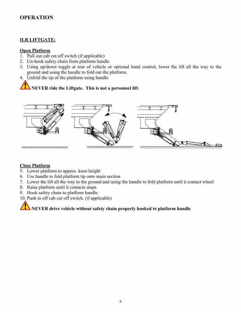
OPERATION ILR LIFTGATE: Open Platform 1. Pull out cab cut off switch (if applicable) 2. Un-hook safety chain from platform handle 3. Using up/down toggle at rear of vehicle or optional hand control, lower the lift all the way to the
ground and using the handle to fold out the platform. 4. Unfold the tip of the platform using handle
NEVER ride the Liftgate. This is not a personnel lift.
Close Platform 5. Lower platform to approx. knee height 6. Use handle to fold platform tip onto main section 7. Lower the lift all the way to the ground and using the handle to fold platform until it contact wheel 8. Raise platform until it contacts stops. 9. Hook safety chain to platform handle. 10. Push in off cab cut off switch. (if applicable)
NEVER drive vehicle without safety chain properly hooked to platform handle
6

OPERATION OF HAND HELD (Optional)
Lift UpLower Down
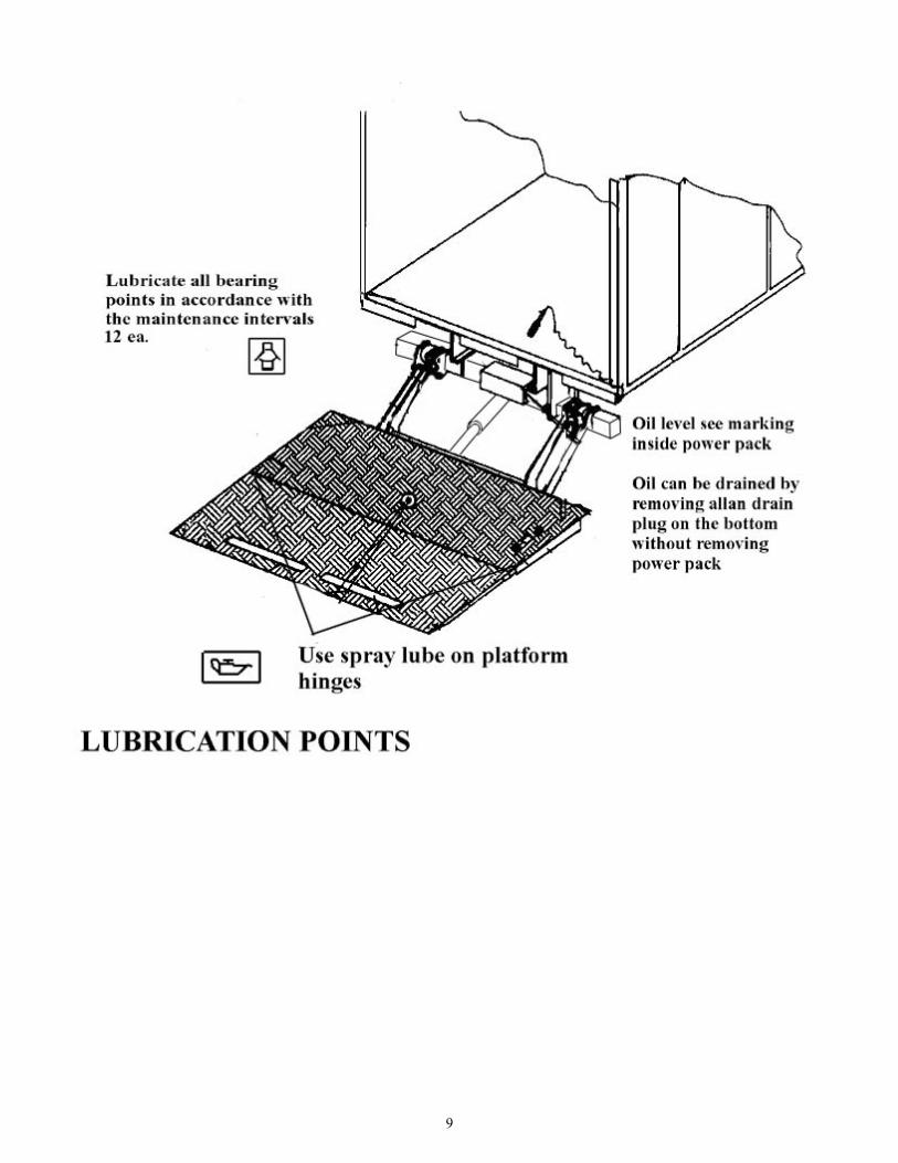
PREVENTIVE MAINTENANCE AND QUICK CHECK. The Interlift ILR needs preventive maintenance to perform at its fullest. Lubricate and inspect regularly. Also, check that all details are not damaged: Hoses, cables, etc. Inspection Check daily: • All hoses, oil leakage. • Safety chain, hook and hook latch • Mounting brackets and bolts connection liftgate to frame and mount frame. • Electric wires and connections. • REPAIR OR REPLACE IMMEDIATELY FAULTY PARTS. LUBRICATION Properly lubricated the Interlift ILR will ensure longevity. Therefore, lubricate the lift at the same time as the truck. Grease more frequently if the liftgate is heavily used. The liftgate should be greased every 150 cycles. Check the oil level in the tank. The level should be between the two marks when the platform is tilted down at ground level. Use a good quality of hydraulic fluid, ISO 32. Change oil at least once a year, referable in the fall before the weather gets cold since the operation of the liftgate will accumulate condensation and some dirt, which can interfere with the liftgates functions. MAINTENANCE & CARE The following inspection and maintenance should be performed at the recommended intervals depending on operation and amount of cycles or at time when the unit shows any signs of damage of abuse. Remember that the secret to a long lift of your INTERLIFT Liftgate is to maintain it through preventive care.
7

CHANGING THE OIL
INTERLIFT HYDRAYLIC FLUIDS AND LUBRICATION RECOMENDATION TEMP. RANGE BRAND -10 TO 150 F EXXON UNIVIS J26 MOBIL OIL DTE 13M CHEVRON AW MV32 ROSEMEAD MV 150 (32) -50 TO 150 F MOBIL DTE 13M SHELL AERO FLUID 4 EXTREME COLD TEMPERATURE: USE MILITARY SPEC: MIL H5606
8
9
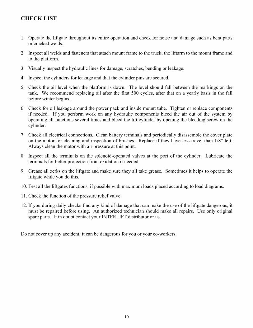
CHECK LIST 1. Operate the liftgate throughout its entire operation and check for noise and damage such as bent parts
or cracked welds. 2. Inspect all welds and fasteners that attach mount frame to the truck, the liftarm to the mount frame and
to the platform. 3. Visually inspect the hydraulic lines for damage, scratches, bending or leakage. 4. Inspect the cylinders for leakage and that the cylinder pins are secured. 5. Check the oil level when the platform is down. The level should fall between the markings on the
tank. We recommend replacing oil after the first 500 cycles, after that on a yearly basis in the fall before winter begins.
6. Check for oil leakage around the power pack and inside mount tube. Tighten or replace components
if needed. If you perform work on any hydraulic components bleed the air out of the system by operating all functions several times and bleed the lift cylinder by opening the bleeding screw on the cylinder.
7. Check all electrical connections. Clean battery terminals and periodically disassemble the cover plate
on the motor for cleaning and inspection of brushes. Replace if they have less travel than 1/8” left. Always clean the motor with air pressure at this point.
8. Inspect all the terminals on the solenoid-operated valves at the port of the cylinder. Lubricate the
terminals for better protection from oxidation if needed. 9. Grease all zerks on the liftgate and make sure they all take grease. Sometimes it helps to operate the
liftgate while you do this. 10. Test all the liftgates functions, if possible with maximum loads placed according to load diagrams. 11. Check the function of the pressure relief valve. 12. If you during daily checks find any kind of damage that can make the use of the liftgate dangerous, it
must be repaired before using. An authorized technician should make all repairs. Use only original spare parts. If in doubt contact your INTERLIFT distributor or us.
Do not cover up any accident; it can be dangerous for you or your co-workers. 10

Please check the following points before calling for tech help: • Is the liftgate switched “ON” at control device in cab or in control box? • Is the battery main switch on? (if applicable) • Is there a main circuit breaker in line to the liftgate? • Is the fuse in power pack OK? • Are the vehicle batteries OK and charged? • Is the connection to ground in power pack OK; is the connection to ground from liftgate to vehicle
OK? • Oil level in oil tank OK? • Any damages on mechanical or electrical element such as damaged cables? • Is the main connection plug in power pack pushed together? Please change oil after working on hydraulic unit (remove of valve, opening of cylinder etc.) Do not alter factory supplied electrical components in anyway. Serious injury or death may occur. Dangerous injuries possible if short circuits arise caused by tools on the main battery connections. ATTENTION: Disconnect main battery supply while working on liftgate
Contact address: INTERLIFT INC. 15939 Piuma Ave
Cerritos, CA 90703
After Sales Service
Contact Person: Craig Lopshire (x13) or “Sands” Sandzimier (x17)
Tel: (562) 924-8218 Fax: (562) 924-8318
11
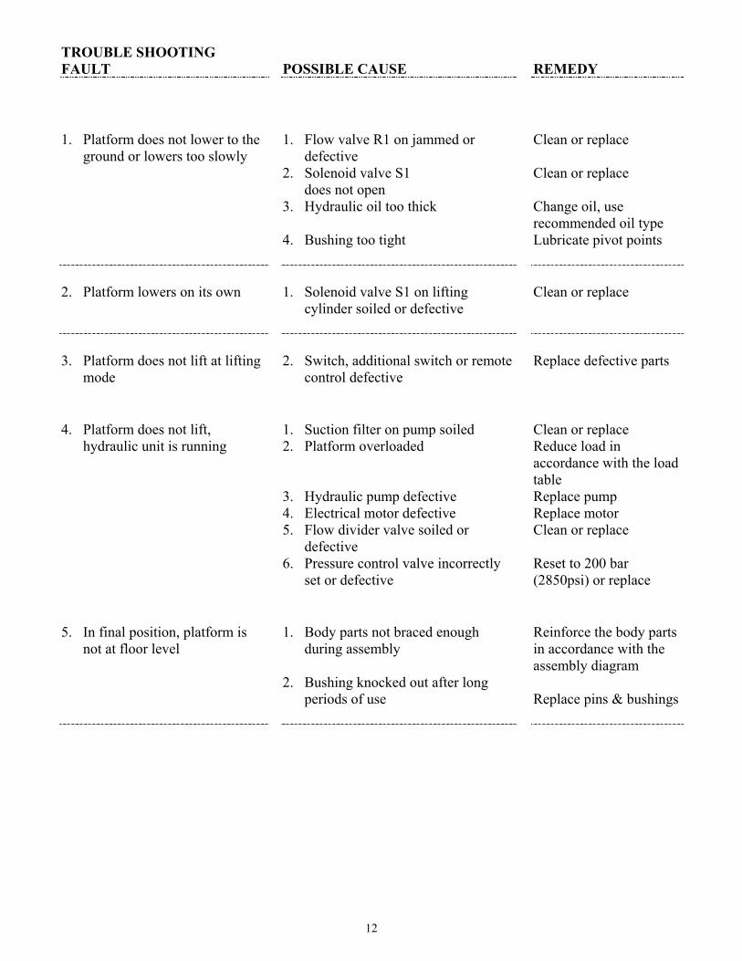
TROUBLE SHOOTING FAULT 1. Platform does not lower to the
ground or lowers too slowly 2. Platform lowers on its own 3. Platform does not lift at lifting
mode 4. Platform does not lift,
hydraulic unit is running 5. In final position, platform is
not at floor level
POSSIBLE CAUSE 1. Flow valve R1 on jammed or
defective 2. Solenoid valve S1 does not open 3. Hydraulic oil too thick 4. Bushing too tight 1. Solenoid valve S1 on lifting
cylinder soiled or defective 2. Switch, additional switch or remote
control defective 1. Suction filter on pump soiled 2. Platform overloaded 3. Hydraulic pump defective 4. Electrical motor defective 5. Flow divider valve soiled or
defective 6. Pressure control valve incorrectly
set or defective 1. Body parts not braced enough
during assembly 2. Bushing knocked out after long
periods of use
REMEDY Clean or replace Clean or replace Change oil, use recommended oil type Lubricate pivot points Clean or replace Replace defective parts Clean or replace Reduce load in accordance with the load table Replace pump Replace motor Clean or replace Reset to 200 bar (2850psi) or replace Reinforce the body parts in accordance with the assembly diagram Replace pins & bushings
12

ORDERING SPARE PARTS, REPAIRS, SETTLING CASES OF WARRANTY SPARE PARTS In order to guarantee quick delivery of spare parts, please always state the following when making orders: 1. Tail lift model & serial number 2. Designation and number of the spare part in accordance with the spare parts list 3. Designation and number marked on the individual component (if available) REPAIRS Parts sent to us to repair must be accompanied by a letter (in separate cover) giving details and scope of the repairs required. WARRANTY We provide warranty as part of our conditions of delivery for 1 year (Parts & Labor). Spare part deliveries are first of all billed. We then issue credit for all or part of the invoiced sum, once we have been able to convince ourselves that the warranty claim is justified as defined by our warranty conditions. We do this by inspecting the defected parts, which are sent back to us freight-prepaid as well as the written description of the problem, which must have been filled out in full. The parts that are sent back to us, marked with serial number and address, become our property if the warranty claim is accepted.
13
14
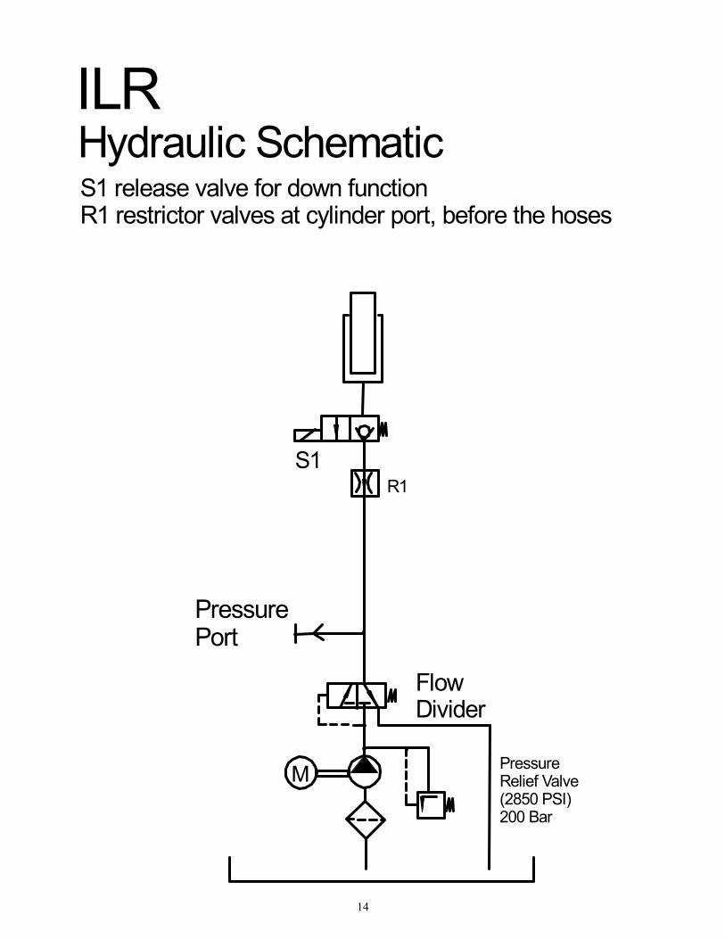
M
R1
PressureRelief Valve(2850 PSI)200 Bar
Flow Divider
PressurePort
S1
ILRHydraulic SchematicS1 release valve for down function R1 restrictor valves at cylinder port, before the hoses
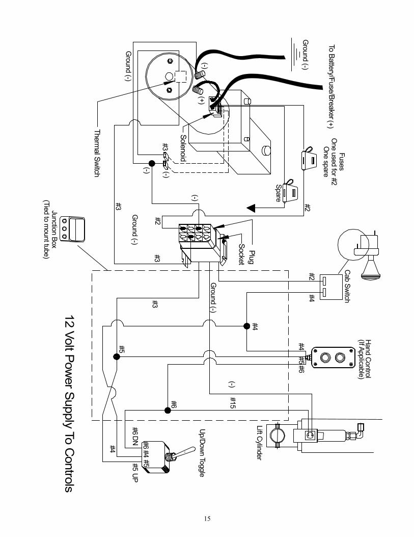
(-)
12 Volt Power Supply To
Thermal Switch
To Battery/Fuse/Breaker
#6DN
#5
#6
#15
Ground (-)
#4
#4#5
#6
#6
#3#3
#3
#3
#2
#2#2
#4
(-)
(-)
(-)
Spare
Ground (-)
Ground (-)
FusesO
ne used for #2O
ne spare
Cab Switch
Hand Control(If Applicable)
Lift Cy
Up/D
Junction Box(Tied to m
ount tube)
Ground (-)
PlugSocket
(+)(-)
Solenoid
(+)
Controls
#5UP
#4 #4#5
linder
own Toggle
15

16


