Interference and Diffraction of Light - Lnu.sehomepage.lnu.se/staff/pkumsi/1FY803/Diffraktion...
6
Interference and Diffraction (ScienceWorkshop) EX-9918 Page 1 of 6 Written by Ann Hanks Interference and Diffraction of Light EQUIPMENT INCLUDED: 1 Basic Optics Track, 1.2 m OS-8508 1 Basic Optics Slit Accessory OS-8523 1 Basic Optics Diode Laser OS-8525A 1 Aperture Bracket OS-8534 1 Linear Translator OS-8535 1 Light Sensor CI-6504A 1 Rotary Motion Sensor CI-6538 NOT INCLUDED, BUT REQUIRED: 1 ScienceWorkshop 500 or 750 Interface CI-6400 1 DataStudio CI-6870 INTRODUCTION The distances between the central maximum and the diffraction minima for a single slit are measured by scanning the laser pattern with a Light Sensor and plotting light intensity versus distance. Also, the distance between interference maxima for two or more slits are measured. These measurements are compared to theoretical values. Differences and similarities between interference and diffraction patterns are examined. THEORY Diffraction When diffraction of light occurs as it passes through a slit, the angle to the minima (dark spot) in the diffraction pattern is given by a sin Θ = m’λ (m’=1,2,3, …) (1) where "a" is the slit width, θ is the angle from the center of the pattern to the a minimum, λ is the wavelength of the light, and m' is the order (1 for the first minimum, 2 for the second minimum, ...counting from the center out). In Figure 1, the laser light pattern is shown just below the computer intensity versus position graph. The angle theta is measured from the center of the single slit to the first minimum, so m' equals one for the situation shown in the diagram. Figure 1: Single-Slit Diffraction
Transcript of Interference and Diffraction of Light - Lnu.sehomepage.lnu.se/staff/pkumsi/1FY803/Diffraktion...

Interference and Diffraction (ScienceWorkshop) EX-9918 Page 1 of 6
Written by Ann Hanks
Interference and Diffraction of Light EQUIPMENT INCLUDED: 1 Basic Optics Track, 1.2 m OS-8508 1 Basic Optics Slit Accessory OS-8523 1 Basic Optics Diode Laser OS-8525A 1 Aperture Bracket OS-8534 1 Linear Translator OS-8535 1 Light Sensor CI-6504A 1 Rotary Motion Sensor CI-6538 NOT INCLUDED, BUT REQUIRED: 1 ScienceWorkshop 500 or 750 Interface CI-6400 1 DataStudio CI-6870
INTRODUCTION The distances between the central maximum and the diffraction minima for a single slit are measured by scanning the laser pattern with a Light Sensor and plotting light intensity versus distance. Also, the distance between interference maxima for two or more slits are measured. These measurements are compared to theoretical values. Differences and similarities between interference and diffraction patterns are examined. THEORY Diffraction When diffraction of light occurs as it passes through a slit, the angle to the minima (dark spot) in the diffraction pattern is given by
a sin Θ = m’λ (m’=1,2,3, …) (1) where "a" is the slit width, θ is the angle from the center of the pattern to the a minimum, λ is the wavelength of the light, and m' is the order (1 for the first minimum, 2 for the second minimum, ...counting from the center out). In Figure 1, the laser light pattern is shown just below the computer intensity versus position graph. The angle theta is measured from the center of the single slit to the first minimum, so m' equals one for the situation shown in the diagram. Figure 1: Single-Slit Diffraction

Interference and Diffraction (ScienceWorkshop) EX-9918 Page 2 of 6
Written by Ann Hanks
Double-Slit Interference When interference of light occurs as it passes through two slits, the angle from the central maximum (bright spot) to the side maxima in the interference pattern is given by d sinΘ=mλ (m=1,2,3, …) (2) where "d" is the slit separation, θ is the angle from the center of the pattern to the mth maximum, λ is the wavelength of the light, and m is the order (0 for the central maximum, 1 for the first side maximum, 2 for the second side maximum ...counting from the center out). In Figure 2, the laser light pattern is shown just below the computer intensity versus position graph. The angle theta is measured from the midway between the double slit to the second side maximum, so m equals two for the situation shown in the diagram. Figure 2: Double-Slit Interference SET UP 1. Mount the Single Slit disk to the optics bench: Each of
the slit disks is mounted on a ring that snaps into an empty lens holder. The ring should be rotated in the lens holder so the slits at the center of the ring are vertical in the holder (see Figure 3). Then the screw on the holder should be tightened so the ring cannot rotate during use. To select the desired slits, just rotate the disk until it clicks into place with the desired slit at the center of the holder.
NOTE: All slits are vertical EXCEPT the comparison slits that are horizontal. The comparison slits are purposely horizontal because the wide laser diode beam will cover both slits to be compared. If you try to rotate these slits to the vertical position, the laser beam may not be large enough to illuminate both slits at the same time.
Figure 3: Mounting the Slits

Interference and Diffraction (ScienceWorkshop) EX-9918 Page 3 of 6
Written by Ann Hanks
2. Mount the Rotary Motion Sensor on the rack of the Linear Translator and mount the Linear Translator to the end of the optics track (see Figure 4). Mount the Light Sensor with the Aperture Bracket (set on slit #6) in the Rotary Motion Sensor rod clamp.
3. To complete the alignment of the laser beam and the slits, place the Diode Laser on the bench at one of the bench. Put the slit holder on the optics bench a few centimeters from the laser, with the disk-side of the holder closest to the laser (see Figure 5). Plug in the Diode Laser and turn it on. CAUTION: Never look into the laser beam.
4. Adjust the position of the laser beam from left-to-right and up-and-down until the beam is
centered on the slit. Once this position is set, it is not necessary to make any further adjustments of the laser beam when viewing any of the slits on the disk. When you rotate the disk to a new slit, the laser beam will be already aligned. Since the slits click into place, you can easily change from one slit to the next, even in the dark. When the laser beam is properly aligned, the diffraction pattern should be centered on the slits in front of the light sensor (see Figure 6). You may have to raise or lower the light sensor to align the pattern vertically.
5. Begin with the Light Sensor gain switch set on x10 and if the intensity goes off scale, turn it down to x1.
Figure 6: Aligning the Light Sensor
Figure 5: Adjusting the Laser
Figure 4: Scanner with Light Sensor
Interference and Diffraction (ScienceWorkshop) EX-9918 Page 4 of 6
Written by Ann Hanks
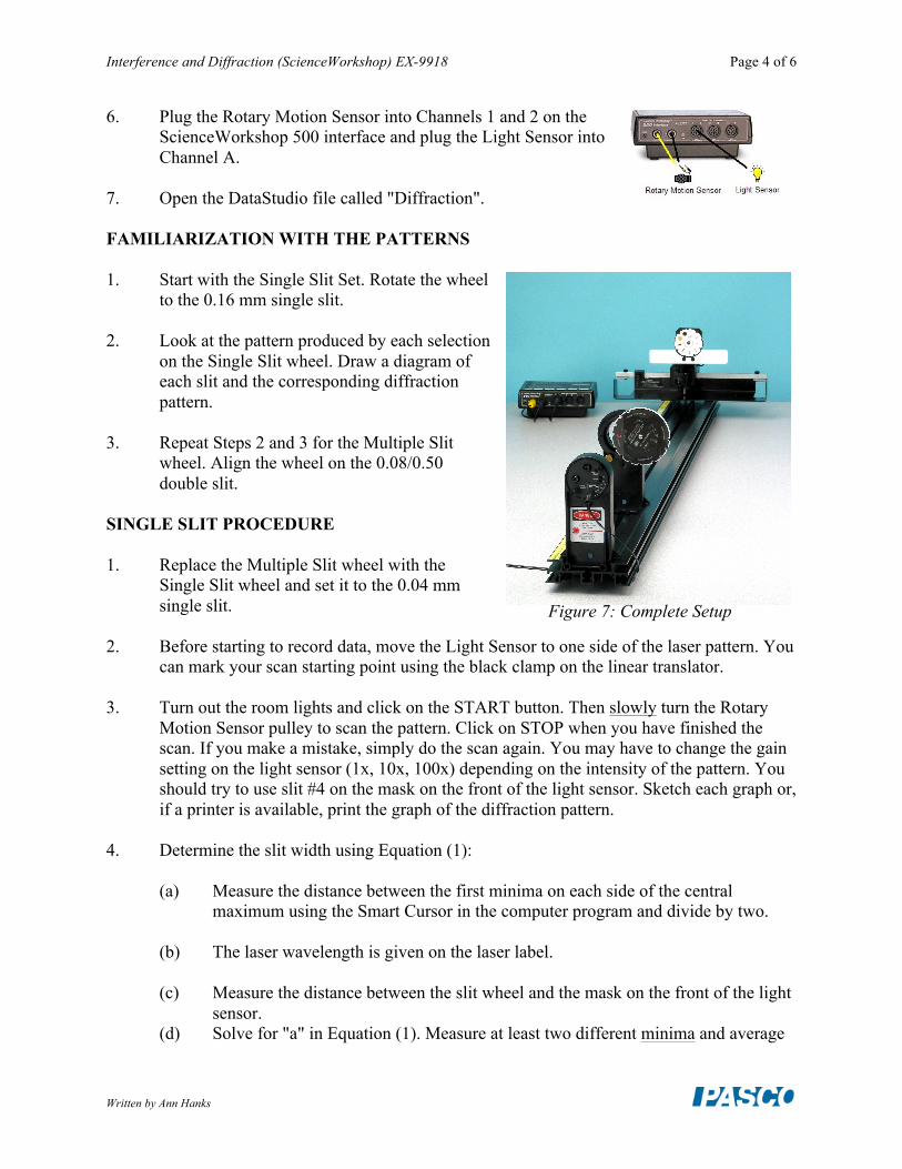
6. Plug the Rotary Motion Sensor into Channels 1 and 2 on the ScienceWorkshop 500 interface and plug the Light Sensor into Channel A.
7. Open the DataStudio file called "Diffraction". FAMILIARIZATION WITH THE PATTERNS
1. Start with the Single Slit Set. Rotate the wheel
to the 0.16 mm single slit. 2. Look at the pattern produced by each selection
on the Single Slit wheel. Draw a diagram of each slit and the corresponding diffraction pattern.
3. Repeat Steps 2 and 3 for the Multiple Slit
wheel. Align the wheel on the 0.08/0.50 double slit.
SINGLE SLIT PROCEDURE 1. Replace the Multiple Slit wheel with the
Single Slit wheel and set it to the 0.04 mm single slit.
2. Before starting to record data, move the Light Sensor to one side of the laser pattern. You
can mark your scan starting point using the black clamp on the linear translator. 3. Turn out the room lights and click on the START button. Then slowly turn the Rotary
Motion Sensor pulley to scan the pattern. Click on STOP when you have finished the scan. If you make a mistake, simply do the scan again. You may have to change the gain setting on the light sensor (1x, 10x, 100x) depending on the intensity of the pattern. You should try to use slit #4 on the mask on the front of the light sensor. Sketch each graph or, if a printer is available, print the graph of the diffraction pattern.
4. Determine the slit width using Equation (1): (a) Measure the distance between the first minima on each side of the central
maximum using the Smart Cursor in the computer program and divide by two. (b) The laser wavelength is given on the laser label. (c) Measure the distance between the slit wheel and the mask on the front of the light
sensor. (d) Solve for "a" in Equation (1). Measure at least two different minima and average
Figure 7: Complete Setup
Interference and Diffraction (ScienceWorkshop) EX-9918 Page 5 of 6
Written by Ann Hanks
your answers. Find the percent difference between your average and the stated slit width on the wheel. Note that the stated slit width is given to only one significant figure so the actual slit width is somewhere between 0.035mm and 0.044mm.
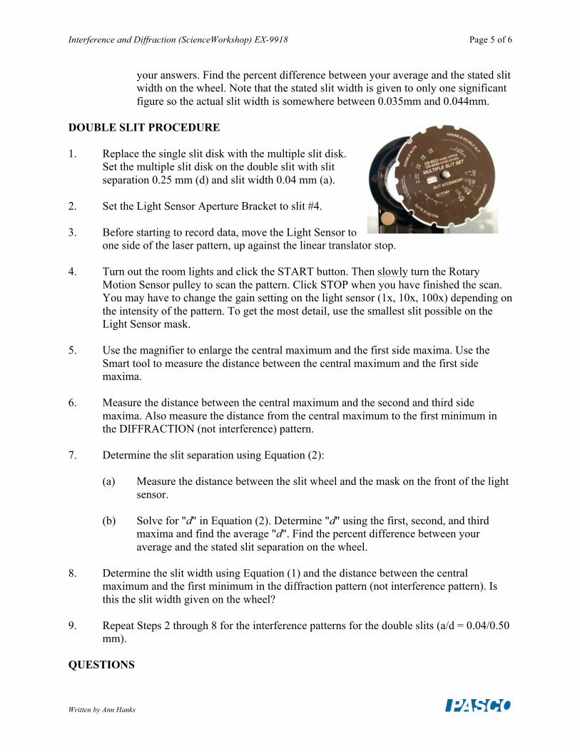
DOUBLE SLIT PROCEDURE 1. Replace the single slit disk with the multiple slit disk.
Set the multiple slit disk on the double slit with slit separation 0.25 mm (d) and slit width 0.04 mm (a).
2. Set the Light Sensor Aperture Bracket to slit #4. 3. Before starting to record data, move the Light Sensor to
one side of the laser pattern, up against the linear translator stop. 4. Turn out the room lights and click the START button. Then slowly turn the Rotary
Motion Sensor pulley to scan the pattern. Click STOP when you have finished the scan. You may have to change the gain setting on the light sensor (1x, 10x, 100x) depending on the intensity of the pattern. To get the most detail, use the smallest slit possible on the Light Sensor mask.
5. Use the magnifier to enlarge the central maximum and the first side maxima. Use the
Smart tool to measure the distance between the central maximum and the first side maxima.
6. Measure the distance between the central maximum and the second and third side
maxima. Also measure the distance from the central maximum to the first minimum in the DIFFRACTION (not interference) pattern.
7. Determine the slit separation using Equation (2): (a) Measure the distance between the slit wheel and the mask on the front of the light
sensor. (b) Solve for "d" in Equation (2). Determine "d" using the first, second, and third
maxima and find the average "d". Find the percent difference between your average and the stated slit separation on the wheel.
8. Determine the slit width using Equation (1) and the distance between the central
maximum and the first minimum in the diffraction pattern (not interference pattern). Is this the slit width given on the wheel?
9. Repeat Steps 2 through 8 for the interference patterns for the double slits (a/d = 0.04/0.50
mm). QUESTIONS

Interference and Diffraction (ScienceWorkshop) EX-9918 Page 6 of 6
Written by Ann Hanks
1. What physical quantity is the same for the single slit and the double slit? 2. How does the distance from the central maximum to the first minimum in the single-slit
pattern compare to the distance from the central maximum to the first diffraction minimum in the double-slit pattern?
3. What physical quantity determines where the amplitude of the interference peaks goes to
zero? 4. In theory, how many interference maxima should be in the central envelope for a double
slit with d = 0.25 mm and a = 0.04 mm? 5. How many interference maxima are actually in the central envelope?