xPublish Output Processing Guide B58 · TableofContents ResamplingImages.....22

ARIB STD-B58Version 1.0-E1
ARIB STANDARD
Association of Radio Industries and Businesses
ARIB STD-B58 Version 1.0
INTERFACE FOR UHDTV PRODUCTION
SYSTEMS
Version 1.0 March 18, 2014
ENGLISH TRANSLATION

General Notes to the English Translation of ARIB Standards
and Technical Reports
1. Notes on Copyright
- The copyright of this document is ascribed to the Association of Radio Industries and
Businesses (ARIB).
- All rights reserved. No part of this document may be reproduced, stored in a retrieval system
or transmitted, in any form or by any means, without the prior written permission of ARIB.
2. Notes on English Translation
- ARIB Standards and Technical Reports are usually written in Japanese. This document is a
translation into English of the original document for the purpose of convenience of users. If
there are any discrepancies in the content, expressions, etc. between the original document
and this translated document, the original document shall prevail.
- ARIB Standards and Technical Reports, in the original language, are made publicly available
through web posting. The original document of this translation may have been further revised
and therefore users are encouraged to check the latest version at an appropriate page under the
following URL:
http://www.arib.or.jp/english/index.html.

ARIB STD-B58
Foreword
The Association of Radio Industries and Businesses (ARIB) investigates and summarizes the
basic technical requirements for various radio systems in the form of “ARIB Standards”. These
standards are developed with the participation of and through discussions amongst radio
equipment manufacturers, telecommunication operators, broadcasting equipment
manufacturers, broadcasters and users.
ARIB Standards include “government technical regulations” (mandatory standard) that are
set for the purpose of encouraging effective use of frequency and preventing interference with
other spectrum users, and “private technical standards” (voluntary standards) that are defined
in order to ensure compatibility and adequate quality of radio equipment and broadcasting
equipment as well as to offer greater convenience to radio equipment manufacturers,
telecommunication operators, broadcasting equipment manufacturers, broadcasters and users.
This ARIB Standard is developed for “INTERFACE FOR UHDTV PRODUCTION SYSTEMS”.
In order to ensure fairness and transparency in the defining stage, the standard was set by
consensus at the ARIB Standard Assembly with the participation of both domestic and foreign
interested parties from radio equipment manufacturers, telecommunication operators,
broadcasting equipment manufacturers, broadcasters and users.
ARIB sincerely hopes that this ARIB Standard will be widely used by radio equipment
manufacturers, telecommunication operators, broadcasting equipment manufacturers,
broadcasters and users.
NOTE:
Although this ARIB Standard contains no specific reference to any essential Industrial
Property Rights relating thereto, the holders of such Essential Industrial Property Rights state
to the effect that the rights listed in the Attachment 1 and 2, which are the Industrial Property
Rights relating to this standard, are held by the parties also listed therein, and that to the
users of this standard, in the case of Attachment 1, such holders shall not assert any rights and
shall unconditionally grant a license to practice such Industrial Property Rights contained
therein, and in the case of Attachment 2, the holders shall grant, under reasonable terms and

ARIB STD-B58
conditions, a non-exclusive and non-discriminatory license to practice the Industrial Property
Rights contained therein. However, this does not apply to anyone who uses this ARIB Standard
and also owns and lays claim to any other Essential Industrial Property Rights of which is
covered in whole or part in the contents of the provisions of this ARIB Standard.
Attachment 2 (selection of option 2)
PATENT HOLDER NAME OF PATENT REGISTRATION NO./
APPLICATION NO.
REMARKS
Sony Corporation (*) Comprehensive confirmation of ARIB STD-B58
version 1.0 is submitted.
(*) Received on March 11, 2014

ARIB STD-B58
-i-
Contents
Foreword
Chapter 1 : General Descriptions ..................................................................................................... 3
1.1 Objective .................................................................................................................................. 3
1.2 Scope ........................................................................................................................................ 3
1.3 References ................................................................................................................................ 3
1.3.1 Normative References ...................................................................................................... 3
1.4 Bibliography ............................................................................................................................ 3
1.5 Definition of Terms ................................................................................................................. 3
Chapter 2 : Data ............................................................................................................................... 5
2.1 Video data ................................................................................................................................ 5
2.2 Ancillary data .......................................................................................................................... 5
Chapter 3 : Mapping to Basic Images .............................................................................................. 7
3.1 Overview of mapping from 8K or 4K images to 10G link signals ......................................... 7
3.1.1 Mapping of 8K or 4K images with 120 Hz or 120/1.001 Hz frame frequency ............... 7
3.1.2 Mapping of 8K or 4K images with 60 Hz or 60/1.001 Hz frame frequency ................... 8
3.1.3 Configuration of colour signal component and system ID .............................................. 9
3.2 Division of 8K images into 4K Sub-Images ......................................................................... 11
3.3 Division of 4K images and 4K Sub-Images into basic images ............................................ 12
Chapter 4 : Basic Stream ............................................................................................................... 15
4.1 Conversion from basic images to basic streams .................................................................. 15
4.2 Timing reference codes (SAV and EAV) ............................................................................... 17
4.3 Line number data .................................................................................................................. 18
4.4 Error detection code data ...................................................................................................... 18
4.5 Ancillary data ........................................................................................................................ 19
4.6 Payload ID ............................................................................................................................. 20
4.7 Blanking data ........................................................................................................................ 21
Chapter 5 : Generation of 10G link signals ................................................................................... 23
5.1 Generating 10G link signals from basic streams ................................................................ 23
5.1.1 Generating 10G link signals from 120 Hz basic streams ............................................. 23
5.1.2 Generating 10G link signals from 60 Hz basic streams ............................................... 27
5.2 Mapping of 8K or 4K image to 10G link signals .................................................................. 30
5.2.1 8K/120 ............................................................................................................................. 30
5.2.2 8K/60 ............................................................................................................................... 33

ARIB STD-B58
-ii-
5.2.3 4K/120 ............................................................................................................................. 35
5.2.4 4K/60 ............................................................................................................................... 37
Chapter 6 : Physical Layer ............................................................................................................. 39
6.1 Transmitter characteristics .................................................................................................. 39
6.2 Receiver characteristics ........................................................................................................ 40
6.3 Jitter specifications ............................................................................................................... 40
6.4 Timing difference between 10G link signals ....................................................................... 41
6.5 Connector ............................................................................................................................... 41
6.6 Assignment of 10G link signals to a receptacle connector .................................................. 45

ARIB STD-B58
-3-
Chapter 1 : General Descriptions
1.1 Objective
This standard defines the optical interface for transmission of the data specified by ARIB
STD-B56 Version 1.1, “UHDTV System Parameters for Programme Production”.
1.2 Scope
This standard applies to the input or output interfaces of studio equipment for transmitting
or receiving the data specified by ARIB STD-B56 Version 1.1, “UHDTV System Parameters for
Programme Production”.
1.3 References
1.3.1 Normative References
(1) ARIB STD-B56 Version 1.1, “UHDTV System Parameters for Programme Production”
(2) ANSI INCITS 230-1994 (R1999), “Information Technology - Fibre Channel - Physical and
Signaling Interface (FC-PH) ”
(3) IEEE 802.3ae–2002, Amendment, “Media Access Control (MAC) Parameters, Physical
Layers, and Management Parameters for 10 Gb/s Operation”
(4) JIS C 5964-7:2010, “Fiber optic connector interfaces - Part 7: Type MPO connector family
(F13) ”
1.4 Bibliography
(1) BTA S-002C, “Digital Representation and Bit-parallel Interface for 1125/60 HDTV
Production Systems”
(2) BTA S-004C, “Bit-serial Digital Interface for 1125/60 HDTV Systems”
(3) BTA S-005C, “Ancillary Data Packet and Space Formatting of Bit-serial Digital Interface
for 1125/60 HDTV Systems”
(4) BTA S-006C, “Audio Data Format of Bit-serial Digital Interface for 1125/60 HDTV
Systems”
1.5 Definition of Terms
Table 1-1 defines the terms in this standard.

ARIB STD-B58
-4-
Table 1-1 Definition of Terms
8K image 7680 × 4320 pixel image specified by ARIB STD-B56 Version 1.1,
“UHDTV System Parameters for Programme Production”
4K image 3840 × 2160 pixel image specified by ARIB STD-B56 Version 1.1,
“UHDTV System Parameters for Programme Production”
4K Sub-Image 3840 × 2160 pixel image of each colour component obtained by
sub-sampling of an 8K image
Basic image 1920 × 1080 pixel image of each colour component obtained by
sub-sampling of a 4K image or 4K Sub-Image
8K/120 8K image with frame frequency of 120 Hz or 120/1.001 Hz
8K/60 8K image with frame frequency of 60 Hz or 60/1.001 Hz
4K/120 4K image with frame frequency of 120 Hz or 120/1.001 Hz
4Ks/120 4K Sub-Image with frame frequency of 120 Hz or 120/1.001 Hz
4K/60 4K image with frame frequency of 60 Hz or 60/1.001 Hz
4Ks/60 4K Sub-Image with frame frequency of 60 Hz or 60/1.001 Hz
2K/120 Basic image with frame frequency of 120 Hz or 120/1.001 Hz
2K/60 Basic image with frame frequency of 60 Hz or 60/1.001 Hz
Basic stream A 12-bit-word multiplexed data stream which consists of a four-word
EAV (End of Active Video) timing reference code, a two-word line
number (LN), a two-word CRCC (Cyclic Redundancy Check Code)
error detection code, ancillary data or blanking data, a four-word SAV
(Start of Active Video) timing reference code, and video data
120 Hz Basic
stream
Basic stream generated from 2K/120
60 Hz Basic
stream
Basic stream generated from 2K/60
Active line 1920 words of data that constitute one line of a basic image
Active frame 1080 lines that include all active lines
Frame blanking The 45 lines between an active frame and the next active frame
000h Hexadecimal 000. In general, hexadecimal digits (0 to 9 and A to F)
with “h” represents a hexadecimal number.
Running
disparity
A binary parameter indicating the cumulative disparity (positive or
negative) of all previously issued transmission characters

ARIB STD-B58
-5-
Chapter 2 : Data
2.1 Video data
Video data is specified by ARIB STD-B56 Version 1.1, “UHDTV System Parameters for
Programme Production”.
2.2 Ancillary data
Ancillary data is specified by other ARIB Standards and Technical Reports.

ARIB STD-B58
-6-
<Blank Page>

ARIB STD-B58
-7-
Chapter 3 : Mapping to Basic Images
3.1 Overview of mapping from 8K or 4K images to 10G link signals
3.1.1 Mapping of 8K or 4K images with 120 Hz or 120/1.001 Hz frame frequency
The mapping of 8K images with 120 Hz or 120/1.001 Hz frame frequency to multiple 10G link
signals is illustrated in Fig. 3-1 and the mapping of 4K images with 120 Hz or 120/1.001 Hz
frame frequency is illustrated in Fig. 3-2. The colour components, C1, C2, and C3 of each figure
are respectively represented as Y, CB, and CR or G, B, and R.
For 8K/120, the three colour components that constitute the image are respectively divided
into four to produce N (N = 6, 8, or 12) 4K Sub-Images, each of which is then further divided to
produce 4N basic images. Those 4N basic images are converted to 4N basic streams, each two of
which are mapped to one 10G link signal to generate 2N 10G link signals.
For 4K/120, the three colour components that constitute the image are respectively divided
into four to produce M (M = 6, 8, or 12) basic images. The M basic images are then converted to
M basic streams, each two of which are mapped to one 10G link signal to generate four or six
10G link signals. The reason for there being no M/2 is that 10G link signals are generated for
each colour component. Detailed specifications are in section 5.2.3.
Figure 3-1 Mapping overview of 8K/120

ARIB STD-B58
-8-
4K, 60Hz
4K Image
Basic Image(1~M)
M = 6, 8, 12
2K/120
2
1
M-1
M
4K, 60Hz4K/120
C1, C2, C3:Colour components
Y, CB, CR
G, B, R
10G Link(1~4 or 1~6)
1
Basic Stream(1~M)
2
1
4 or 6M-1
M
C1C2C3
4
3 2
4
3
Figure 3-2 Mapping overview of 4K/120
3.1.2 Mapping of 8K or 4K images with 60 Hz or 60/1.001 Hz frame frequency
The mapping of 8K images with 60 Hz or 60/1.001 Hz frame frequency to multiple 10G link
signals is illustrated in Fig. 3-3 and the mapping of 4K images with 60 Hz or 60/1.001 Hz frame
frequency is illustrated in Fig. 3-4.
For 8K/60, the three colour components that constitute the image are respectively divided
into four to produce N (N = 6, 8, or 12) 4K Sub-Images, and then 4N basic images are generated.
Next, the 4N basic images are converted to 4N basic streams, each four of which are mapped to
one 10G link signal to generate N 10G link signals.
For 4K/60, the three colour components that constitute the image are respectively divided
into four to produce M (M = 6, 8, or 12) basic images. The M basic images are then converted to
M basic streams, each four of which are mapped to one 10G link signal to generate three 10G
link signals. The reason for there being no M/4 is that 10G link signals are generated for each
colour component. Detailed specifications are in section 5.2.4.

ARIB STD-B58
-9-
Figure 3-3 Mapping overview of 8K/60
4K, 60Hz
4K Image
Basic Image(1~M)
M = 6, 8, 12
2K/602
3
4
1
M-2
M-1
M
M-3
4K, 60Hz4K/60
10G Link(1~3)
1
Basic Stream(1~M)
2
3
4
1
3M-2
M-1
M
M-3
C1C2C3
C1, C2, C3:Colour components
Y, CB, CR
G, B, R
Figure 3-4 Mapping overview of 4K/60
3.1.3 Configuration of colour signal component and system ID
Figure 3-5 illustrates the image division of 8K images into 4K Sub-Images and 4K images
into basic images when the sampling structures for 8K images and 4K images are 4:2:2 (YCBCR)
or 4:2:0 (YCBCR).

ARIB STD-B58
-10-
For the 4:2:2 (YCBCR) sampling structure, the colour components of the 4K Sub-Images
generated from the 8K images are limited to Y1, Y2, Y3, Y4, CB1, CB3, CR1, and CR3 and the
colour components of the basic images generated from the 4K image are limited to y1, y2, y3, y4,
cB1, cB3, cR1, and cR3.
For the sampling structure 4:2:0 (YCBCR), the colour components of the 4K Sub-Images
generated from the 8K images are limited to Y1, Y2, Y3, Y4, CB1, CR1 and the colour
components of the basic images generated from the 4K image are limited to y1, y2, y3, y4, cB1,
and cR1.
Figure 3-5 Image division of 4:2:2 (YCBCR) and 4:2:0 (YCBCR) systems
The system numbers for identifying the image format are defined in Table 3-1 for 8K images
and in Table 3-2 for 4K images.

ARIB STD-B58
-11-
Table 3-1 The numbers of 10G links and the system numbers for 8K images
8K Image,
Sampling
Structure
4K Sub-Image
Frame
Frequency (Hz)
Number of
10G Links
System
Number
Number of
Sub-Images
(N)
Elements of Colour
Components
8K,
4:4:4 (GBR) 12
G1, G2, B1, B2, R1, R2,
G3, G4, B3, B4, R3, R4
120, 120/1.001 24 U2.1
60, 60/1.001 12 U2.3
8K,
4:4:4 (YCBCR) 12
Y1, Y2, CB1, CB2, CR1, CR2,
Y3, Y4, CB3, CB4, CR3, CR4
120, 120/1.001 24 U2.8
60, 60/1.001 12 U2.10
8K,
4:2:2 (YCBCR) 8
Y1, Y2, CB1, CR1,
Y3, Y4, CB3, CR3
120, 120/1.001 16 U2.15
60, 60/1.001 8 U2.17
8K,
4:2:0 (YCBCR) 6
Y1, Y2, CB1, CR1,
Y3, Y4
120, 120/1.001 12 U2.22
60, 60/1.001 6 U2.24
Table 3-2 The numbers of 10G links and the system numbers for 4K images
4K Image,
Sampling
Structure
Basic Image
Frame
Frequency (Hz)
Number of
10G Links
System
Number
Number of
Basic
Images (M)
Elements of Colour
Components
4K,
4:4:4 (GBR) 12
g1, g2, b1, b2, r1, r2,
g3, g4, b3, b4, r3, r4
120, 120/1.001 6 U1.1
60, 60/1.001 3 U1.3
4K,
4:4:4 (YCBCR) 12
y1, y2, cB1, cB2, cR1, cR2,
y3, y4, cB3, cB4, cR3, cR4
120, 120/1.001 6 U1.8
60, 60/1.001 3 U1.10
4K,
4:2:2 (YCBCR) 8
y1, y2, cB1, cR1,
y3, y4, cB3, cR3
120, 120/1.001 4 U1.15
60, 60/1.001 3 U1.17
4K,
4:2:0 (YCBCR) 6
y1, y2, cB1, cR1,
y3, y4
120, 120/1.001 4 U1.22
60, 60/1.001 3 U1.24
3.2 Division of 8K images into 4K Sub-Images
The division of 8K images into 4K Sub-Images is illustrated in Fig. 3-6. In the line numbering
for each 8K image sample, the uppermost line in the vertical direction is line number 1 and the
lowermost line is line number 4320; the leftmost sample in the horizontal direction is sample
number 0 and the rightmost sample is sample number 7679. The numbering for each sample of
the 4K Sub-Images is done similarly, with the uppermost line in the vertical direction as line

ARIB STD-B58
-12-
number 1 and the lowest line as line number 2160, and the leftmost sample in the horizontal
direction as sample number 0 and the rightmost sample as sample number 3839.
The even-numbered samples of the odd lines of the 8K images are mapped to 4K Sub-Image 1
and the odd-numbered samples of the odd lines of the 8K images are mapped to 4K Sub-Image
2; the even-numbered samples of the even lines of the 8K images are mapped to 4K Sub-Image
3 and the odd-numbered samples of the even lines of the 8K images are mapped to 4K
Sub-Image 4.
Figure 3-6 Image division from 8K Images to 4K Sub-Images
3.3 Division of 4K images and 4K Sub-Images into basic images
The division of 4K images and 4K Sub-Images into basic images is illustrated in Fig. 3-7. The
numbering for each sample of the 4K Sub-Images is done in the same way as for the 4K
Sub-Images, with the uppermost line in the vertical direction as line number 1 and the lowest
line as line number 2160, and the leftmost sample in the horizontal direction as sample number
0 and the rightmost sample as sample number 3839. The numbering for each sample of the
basic images is done similarly, with the uppermost line in the vertical direction as line number
1 and the lowest line as line number 1080, and the leftmost sample in the horizontal direction
as sample number 0 and the rightmost sample as sample number 1919.

ARIB STD-B58
-13-
The even-numbered samples of the odd lines of the 4K images and 4K Sub-Images are
mapped to basic image 1 and the odd-numbered samples of the odd lines of the 4K images and
4K Sub-Images are mapped to basic image 2; the even-numbered samples of the even lines of
the 4K images and 4K Sub-Images are mapped to basic image 3 and the odd-numbered samples
of the even lines of the 4K images and 4K Sub-Images are mapped to basic image 4.
Figure 3-7 Image division of 4K Images or 4K Sub-Image into Basic Images

ARIB STD-B58
-14-
<Blank Page>
ARIB STD-B58
-15-
Chapter 4 : Basic Stream
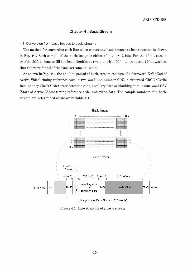
4.1 Conversion from basic images to basic streams
The method for converting each line when converting basic images to basic streams is shown
in Fig. 4-1. Each sample of the basic image is either 10 bits or 12 bits. For the 10 bit case, a
two-bit shift is done to fill the least significant two bits with “00” to produce a 12-bit word so
that the word for all of the basic streams is 12 bits.
As shown in Fig. 4-1, the one line period of basic stream consists of a four-word EAV (End of
Active Video) timing reference code, a two-word line number (LN), a two-word CRCC (Cyclic
Redundancy Check Code) error detection code, ancillary data or blanking data, a four-word SAV
(Start of Active Video) timing reference code, and video data. The sample numbers of a basic
stream are determined as shown in Table 4-1.
Figure 4-1 Line structure of a basic stream

ARIB STD-B58
-16-
Table 4-1 Sample numbers of a basic stream
Item Symbol Sample number
Active line (video data) D 0-1919
Timing reference code (EAV) EAV 1920, 1921, 1922, 1923
Line number data LN LN0 1924
LN1 1925
Cyclic redundancy check codes CRCC CRCC0 1926
CRCC1 1927
Ancillary data or
Blanking data ANC 1928-2195
Timing reference code (SAV) SAV 2196, 2197, 2198, 2199
The frame structure of a basic stream is shown in Fig. 4-2 and the basic stream line
numbering is shown in Table 4-2. A basic stream comprises 1080-line active frame and 45-line
frame blanking intervals. The samples from the first line of a basic image to the 1080th line are
assigned to ones from line 42 to line 1121 of the basic stream. The frame blanking is assigned to
the interval from line 1 to line 41 and from line 1122 to line 1125. The line structure of the
frame blanking is same as that of the active frame shown in Fig. 4-1, with a 1920-word region of
the active line allocated to the ancillary data or blanking data.
Active video area(Basic Image)
42
1121
1
41
1122
1125
Ancillary data orBlanking data
EAVAncillary data or
Blanking data
Frame blanking
Frame blanking
Active frameLN
CR
CC
EA
V
SA
V
Anc
illa
ry d
ata
orB
lank
ing
data
19190
1920
1923
1924
2195
2196
2199
1925
1926
1927
1928
Figure 4-2 Frame structure of a basic stream

ARIB STD-B58
-17-
Table 4-2 Line numbers of a basic stream
Item Line number
Frame blanking 1-41, 1122-1125
Active frame 42-1121
4.2 Timing reference codes (SAV and EAV)
The two timing reference codes are the SAV, which is placed immediately before the video
data (active line), and the EAV, which is placed immediately after the video data. The bit
assignments for the SAV and EAV are shown in Table 4-3 and the protection bit assignments
are shown in Table 4-4.
In Table 4-3 and Table 4-4, F is an identification bit for progressive/interlaced (first/second
field). The images in this standard are progressive, so the value of F is fixed at 0. The V is an
identifier bit for the frame blanking and the active video data. The value of V is 1 in the frame
blanking from line 1 to line 41 and from line 1122 to line 1125; the value is 0 in the active video
data from line 42 to line 1121. The H is an identifier bit that has a value of 0 for SAV and 1 for
EAV. The values P0 through P3 are parity bits, which are used for one bit error correction and
two bits error detection on the receiving side. The assignment of those bits is defined as shown
in Table 4-4.
Table 4-3 Bit assignment for timing reference codes
Word
number Value
Bit number
b11
(MSB)
b10 b9 b8 b7 b6 b5 b4 b3 b2 b1 b0
(LSB)
1 FFFh 1 1 1 1 1 1 1 1 1 1 1 1
2 000h 0 0 0 0 0 0 0 0 0 0 0 0
3 000h 0 0 0 0 0 0 0 0 0 0 0 0
4 XYZ 1 F V H P3 P2 P1 P0 0 0 0 0

ARIB STD-B58
-18-
Table 4-4 Protection bits for timing reference codes
Bit number b10 b9 b8 b7 b6 b5 b4
Function F V H P3 P2 P1 P0
Bit pattern 0 0 0 0 0 0 0 0
Bit pattern 1 0 0 1 1 1 0 1
Bit pattern 2 0 1 0 1 0 1 1
Bit pattern 3 0 1 1 0 1 1 0
4.3 Line number data
The line numbering of the basic stream uses the line numbers for the basic stream specified
in Fig. 4-2 and Table 4-2 rather than the line numbers of the 8K or 4K image. The line number
data is represented in binary format using the 11 bits from L0 (LSB) to L10 (MSB). The bit
assignment of line number data LN0 and LN1 is shown in Table 4-5. The reserved bits of Table
7 are set to "0" until defined.
Table 4-5 Bit assignment for line number data
Bit number LN0 LN1
b11 (MSB) NOT b10 NOT b10
b10 L6 Reserved
b9 L5 Reserved
b8 L4 Reserved
b7 L3 L10 (MSB)
b6 L2 L9
b5 L1 L8
b4 L0 (LSB) L7
b3 Reserved Reserved
b2 Reserved Reserved
b1 Reserved Reserved
b0 (LSB) Reserved Reserved
4.4 Error detection code data
The basic stream error detection code data is represented by the 18 bits from CRCC0 to
CRCC17 and is defined as follows.
(1) Error detection code: CRCC (Cyclic Redundancy Check Code)

ARIB STD-B58
-19-
(2) Polynomial generator equation: C(X) = X18+X5+X4+1. The initial value is set to 0.
(3) Error detection code generation range:
Start point: The first word after the SAV of the previous line
End point: The last word of the line number data
(4) Error detection code generation sequence:
Begin with the LSB of the first word of the error detection code generation range and
end with the MSB of the last word in that range.
(5) Bit assignment:
Table 4-6 specifies the bit assignment. CRCC0 is the MSB of the error detection code.
The reserved bits of Table 4-6 are set to "0" until defined.
Table 4-6 Bit assignment for CRCC
Bit number CRC0 CRC1
b11 (MSB) NOT b10 NOT b10
b10 CRCC8 CRCC17
b9 CRCC7 CRCC16
b8 CRCC6 CRCC15
b7 CRCC5 CRCC14
b6 CRCC4 CRCC13
b5 CRCC3 CRCC12
b4 CRCC2 CRCC11
b3 CRCC1 CRCC10
b2 CRCC0 CRCC9
b1 Reserved Reserved
b0 (LSB) Reserved Reserved
4.5 Ancillary data
Except for Payload ID specified in section 4.6, ancillary data is specified by other ARIB
Standards and Technical Reports.
Until ancillary data for 8K and 4K images is specified, the ancillary data for 1125/P (1125/60
HDTV progressive systems) level A defined by BTA S-004C is applied for basic stream ancillary
data. When applying the data, the specification of Y data stream and the CB/CR data stream of
the 1125/P level A are respectively replaced with basic stream 1 and basic stream 2.

ARIB STD-B58
-20-
When the ancillary data packet is specified as 10 bits/word, the conversion shown in Fig. 4-3
is performed. In Fig. 4-3, ADF indicates an ancillary data flag, DID indicates a data identifier
word, DBN indicates a data block number word, SDID indicates second data identifier word,
DC indicates a data count word, UDW indicates a user data word and CS indicates a checksum
word. As shown in Fig. 4-3, for ancillary data packets specified as 10 bits/word, excluding ADF
and CS, the lowest two bits are filled with "00" to convert to a 12-bit word format and a two bit
shift is applied to the bit assignment specified for the 10-bit words. For the three words of the
ADF, "00" is appended to the lowest two bits of the first word and "11" is appended to the lowest
two bits of the other two words for conversion to 12-bit words. For CS, the lower 11 bits of the
sum of the lower 11 bits of the words from DID to the last UDW are assigned as b0 (LSB) to b10
of CS, and b11 (MSB) is set as the reverse of b10.
Figure 4-3 Conversion of ancillary data packet from 10 bit/word to 12 bit/word
4.6 Payload ID
The UDW bit assignment of Payload ID packet is shown in Table 4-7. The Payload ID packet
must be multiplexed once per frame of the basic stream. The recommended location is
immediately after the CRCC of the basic stream in line 10.

ARIB STD-B58
-21-
Table 4-7 Bit assignment of Payload ID packet
Bit
number Word 1 Word 2 Word 3 Word 4
b11
(MSB) NOT b10 NOT b10 NOT b10 NOT b10
b10 EP
(Note 1)
EP EP EP
b9 1 Progressive (1) Channel assignment
of basic stream
Ch1 (0h), Ch2 (1h),
Ch3 (2h), Ch4 (3h),
10G link
assignment
Ch1 (00h) -
Ch24 (17h)
b8 0 Progressive (1)
b7 1 0
b6 0 0 0
b5 0 Picture rate Sampling structure
identification b4 1 60/1.001 Hz
60 Hz
120/1.001 Hz
120 Hz
(Ah),
(Bh),
(Eh)
(Fh)
0
b3 4K/8K
4K (1h),
8K (2h)
4:2:2 (YCBCR)
4:4:4 (YCBCR)
4:4:4 (GBR)
4:2:0 (YCBCR)
(0h),
(1h),
(2h),
(3h),
Bit depth
10-bit (1h),
12-bit (2h) b2
b1 0 0 0 0
b0
(LSB) 0 0 0 0
Note 1: EP = Even parity for b0 through b9.
4.7 Blanking data
The blanking data words occurring during blanking intervals that are not used for the timing
reference codes (SAV and EAV), line number data, error detection codes or ancillary data are set
as listed below.
(1) Basic streams for colour components Y, G, B, R: 100h
(2) Basic streams for colour components CB, CR: 800h

ARIB STD-B58
-22-
<Blank Page>

ARIB STD-B58
-23-
Chapter 5 : Generation of 10G link signals
5.1 Generating 10G link signals from basic streams
5.1.1 Generating 10G link signals from 120 Hz basic streams
The method for converting two 120 Hz basic streams to one 10G link signal is shown in Fig.
5-1 to Fig. 5-4. First, two 120 Hz basic streams are multiplexed word-by-word and converted to
a multiplexed data stream. Adding 880-word stuffing data to the two 120 Hz basic streams as
shown in Fig. 5-1 results in a data stream that has 5280 words per line period. That stuffing
data, until defined, are filled with 100h.
Figure 5-1 Multiplexing of two 120 Hz basic streams
Next, the word-multiplexed data stream is coded by 8B/10B encoding as specified by ANSI
INCITS 230. The multiplexed data stream consisting of 12-bit words is first converted to a byte
series as shown in Fig. 5-2, and then coded as 8B/10B encoded data.
The conversion to byte series is done in order from the beginning word of the active line,
D0(2), and every two words as shown in Fig. 5-3. After the conversion to byte series, the first
two bytes and the next two bytes of the multiplexed SAV and EAV are replaced with

ARIB STD-B58
-24-
synchronization blocks and content IDs as shown in Fig. 5-4, respectively. The content ID bit
assignment is shown in Table 5-1 and the bit assignment of the system ID, which is part of the
content ID, is shown in Table 5-2.
When doing 8B/10B coding, the synchronization blocks of the multiplexed SAV are replaced
with K28.5 special characters and those of the multiplexed EAV are replaced with K29.7 special
characters defined by ANSI INCITS 230. The 8B/10B encoding process starts at the first K28.5
special character with a negative running disparity. The 8B/10B encoding process is done in
accordance with current running disparity at all the lines that follow.
Figure 5-2 8B/10B encoding of multiplexed data stream generated from 120 Hz basic streams

ARIB STD-B58
-25-
Figure 5-3 Data alignment and 8B/10B encoding of 2-word data block
Figure 5-4 Synchronization header generation by replacement of multiplexed SAV and EAV data
generated from 120 Hz basic streams

ARIB STD-B58
-26-
Table 5-1 Content ID bit assignment
Bit Content ID1 Content ID2
b7 (MSB) Reserved
(0h) Reserved
(0h) b6
b5
System ID
b4
10G link assignment
Ch.1(00h) to Ch.24(17h)
b3
b2
b1
b0 (LSB)
Table 5-2 System ID bit assignment
System
ID
(b5 to b0)
System
Number
System
ID
(b5 to b0)
System
Number
System
ID
(b5 to b0)
System
Number
System
ID
(b5 to b0)
System
Number
000000 U1.1 001110 U1.15 100000 U2.1 101110 U2.15
000001 Reserved 001111 Reserved 100001 Reserved 101111 Reserved
000010 U1.3 010000 U1.17 100010 U2.3 110000 U2.17
000011
~
000110
Reserved
010001
~
010100
Reserved
100011
~
100110
Reserved
110001
~
110100
Reserved
000111 U1.8 010101 U1.22 100111 U2.8 110101 U2.22
001000 Reserved 010110 Reserved 101000 Reserved 110110 Reserved
001001 U1.10 010111 U1.24 101001 U2.10 110111 U2.24
001010
~
001101
Reserved
011000
~
011111
Reserved
101010
~
101101
Reserved
111000
~
111111
Reserved

ARIB STD-B58
-27-
Next, the 8B/10B coded data is serialized in order from the least significant bit (LSB) into the
serial stream of the 10G link signal. The speed of the 10G link signals generated as described
above for 120 Hz frame frequency is 7920 (words/line) × 10 (bits/word) × 1125 (lines) × 120
(1/second), or 10.692 Gbit/s. For the frame frequency of 120/1.001 Hz, the speed is 7920
(words/line) × 10 (bits/word) × 1125 (lines) × 120/1.001 (1/second), or 10.692/1.001 Gbit/s.
5.1.2 Generating 10G link signals from 60 Hz basic streams
The method for converting four 60 Hz basic streams to one 10G link signal is shown in Fig.
5-5 and Fig. 5-7. First, four 60 Hz basic streams are multiplexed word by word and converted to
a multiplexed data stream. Adding 1760-word stuffing data to the four 60 Hz basic streams as
shown in Fig. 5-5 results in a data stream that has 10560 words per line period. The stuffing
data, until defined, are filled with 100h.

ARIB STD-B58
-28-
60 H
zB
asic
Str
eam
1
XYZ(2)XYZ(1)
LN0(2)
LN0(4)
ANC267(4)
LN0(3)
ANC267(3)
D0(4)D0(3)D0(2)D0(1)
U0
U1759
D1919(2)
D1919(4)
D1919(1)
D1919(3)
Mul
tipl
exed
da
ta s
trea
m
Mul
tipl
exed
EA
V(1
6 w
ords
)M
ulti
plex
ed S
AV
(16
wor
ds)
12 b
it/w
ord
12 b
it/w
ord
12 b
it/w
ord
EA
V(4
wor
ds)
SA
V(4
wor
ds)
Mul
tipl
exed
ac
tive
line
(768
0 w
ords
)
1056
0 w
ords
/lin
e
12 b
it/w
ord
12 b
it/w
ord
000h(1)
FFFh(1)
XYZ(1)
000h(1)
LN0(1)
D1919(1)
000h(2)
FFFh(2)
XYZ(2)
000h(2)
LN0(2)
D1919(2)
000h(3)
FFFh(3)
XYZ(3)
000h(3)
LC0(3)
D1919(3)
000h(4)
FFFh(4)
XYZ(4)
000h(4)
LN0(4)
D1919(4)
ANC267(1)
000h(1)
FFFh(1)
XYZ(1)
000h(1)
D0(1)
D1(1)
ANC267(2)
000h(2)
FFFh(2)
XYZ(2)
000h(2)
D0(2)
D1(2)
ANC267(3)
000h(3)
FFFh(3)
XYZ(3)
000h(3)
D0(3)
D1(3)
ANC267(4)
000h(4)
FFFh(4)
XYZ(4)
000h(4)
D0(4)
D1(4)
FFFh(4)FFFh(3)FFFh(2)FFFh(1)000h(4)000h(3)000h(2)000h(1)000h(4)000h(3)000h(2)000h(1)XYZ(4)XYZ(3)
LN0(1)
ANC267(2)ANC267(1)
XYZ(2)XYZ(1)
FFFh(4)FFFh(3)FFFh(2)FFFh(1)000h(4)000h(3)000h(2)000h(1)000h(4)000h(3)000h(2)000h(1)XYZ(4)XYZ(3)
Act
ive
line
(192
0 w
ords
)
60 H
zB
asic
Str
eam
2
60 H
zB
asic
Str
eam
3
60 H
zB
asic
Str
eam
4
LN
/CR
CC
/AN
C(2
72 w
ords
)
Mul
tipl
exed
L
N/C
RC
C/A
NC
(108
0 w
ords
)S
tuff
ing
(176
0 w
ords
)
Figure 5-5 Multiplexing of four 60 Hz Basic Streams

ARIB STD-B58
-29-
Next, the word-multiplexed data stream is coded by 8B/10B encoding as specified by ANSI
INCITS 230. The multiplexed data stream consisting of 12-bit words is first converted to a byte
series as shown in Fig. 5-6, and then coded as 8B/10B encoded data.
The conversion to byte series is done in order from the beginning word of the active line,
D0(4), and every two words in the same way as shown in Fig. 5-3. After the conversion to byte
series, the first two bytes and the next two bytes of the multiplexed SAV and EAV are replaced
with synchronization blocks and content IDs as shown in Fig. 5-7, respectively. The content ID
bit assignment is shown in Table 5-1 and Table 5-2.
When doing 8B/10B coding, the synchronization blocks of the multiplexed SAV are replaced
with K28.5 special characters and those of the multiplexed EAV are replaced with K29.7 special
characters defined by ANSI INCITS 230. The 8B/10B encoding process starts at the first K28.5
special character with a negative running disparity. The 8B/10B encoding process is done in
accordance with current running disparity at all the lines that follow.
Multiplexed LN/CRCC/ANC
Multiplexed active line
Byte alignment
Multiplexed LN/CRCC/ANC
Multi-plexedSAV
Multiplexed active line
8B/10B encoding
Stuffing
8B/10B encoded data
12 bit/word
8 bit/word
10bit/word
Multiplexed data stream
Multiplexed EAV Multiplexed SAVStuffing
Multi-plexedEAV
10560 words
15840 words
15840 words
Replacement with synchronization blocks and content IDs
Figure 5-6 8B/10B encoding of multiplexed data stream generated from 60 Hz basic streams

ARIB STD-B58
-30-
FFF
h(3)
:4-1
1
FFF
h(4)
:0-7
FF
Fh(
4):8
-11
FFF
h(3)
:0-3
FFF
h(1)
:4-1
1
FFF
h(2)
:0-7
FF
Fh(
2):8
-11
FFF
h(1)
:0-3
000h
(3):
4-11
000h
(4):
0-7
000h
(4):
8-11
000h
(3):
0-3
Con
tent
ID
1
Syn
chro
niza
tion
blo
ck
Con
tent
ID
2
Syn
chro
niza
tion
blo
ck
FFF
h(1)
:4-1
1F
FF
h(2)
:8-1
1F
FFh(
1):0
-3
000h
(3):
4-11
000h
(4):
0-7
000h
(4):
8-11
000h
(3):
0-3
Figure 5-7 Synchronization header generation by replacement of multiplexed SAV and EAV data
generated from 60 Hz basic streams
Next, the 8B/10B coded data is serialized in order from the least significant bit (LSB) into the
serial stream of the 10G link signal. The speed of the 10G link signals generated as described
above for 60 Hz frame frequency is 15840 (words/line) × 10 (bits/word) × 1125 (lines) × 60
(1/seconds), or 10.692 Gbit/s. For the frame frequency of 60/1.001 Hz, the speed is 15840
(words/line) × 10 (bits/word) × 1125 (lines) × 60/1.001 (1/second), or 10.692/1.001 Gbit/s.
5.2 Mapping of 8K or 4K image to 10G link signals
5.2.1 8K/120
The mapping of the 8K/120 images listed below to the 10G link signals is illustrated in Fig.
5-8 and Fig. 5-9.
‧ U2.1 (8K/120, GBR, 4:4:4)
‧ U2.8 (8K/120, YCBCR, 4:4:4)
‧ U2.15 (8K/120, YCBCR, 4:2:2)
‧ U2.22 (8K/120, YCBCR, 4:2:0)
The SIp.q (p is an integer greater than or equal to 1 and less than or equal to 4; q is an integer
greater than or equal to 1 and less than or equal to 3) represents the 4K Sub-Image p for colour
component Cq generated by division of the 8K images and is mapped as shown in Fig. 3-6. The
BIu.p.q (u is an integer greater than or equal to 1 and less than or equal to 4) represents the
basic image u generated by further division of 4Ks/120 SIp.q and is mapped as shown in Fig.
3-7. BS1/120 and BS2/120 respectively represent the 120 Hz basic stream 1 and 120 Hz basic
stream 2 specified in Fig. 5-1. For the 8K/120 mapping, one 10 GHz link signal is generated
from the two 120 Hz basic streams. As shown in Fig. 3-5, fewer 4K Sub-Images are generated
from the 8K image for 4:2:2 or 4:2:0 (both YCBCR) than for 4:4:4 (GBR or YCBCR). In Fig. 5-8, the
4K Sub-Images that are appended with *1 are generated with 4:4:4 and 4:2:2, and those
appended with *2 are generated with only 4:4:4.

ARIB STD-B58
-31-
8K, 120Hz8K, 120Hz
8K/120
4Ks/120
2K/12010G Link 1
C1C2
C3
C1
2K/1202K/1202K/120
BS1/120BS1/120BS2/120BS2/120
10G Link 13
4Ks/120
2K/12010G Link 2
2K/1202K/1202K/120
BS1/120BS1/120BS2/120BS2/120
10G Link 14
4Ks/120
2K/12010G Link 3
2K/1202K/1202K/120
BS1/120BS1/120BS2/120BS2/120
10G Link 15
4Ks/120
2K/12010G Link 4
2K/1202K/1202K/120
BS1/120BS1/120BS2/120BS2/120
10G Link 16
4Ks/120
2K/12010G Link 5
C2
2K/1202K/1202K/120
10G Link 17
4Ks/120
2K/12010G Link 6
2K/1202K/1202K/120
10G Link 18
4Ks/120
2K/12010G Link 7
2K/1202K/1202K/120
10G Link 19
4Ks/120
2K/12010G Link 8
2K/1202K/1202K/120
10G Link 20
4Ks/120
2K/12010G Link 9
C3
2K/1202K/1202K/120
10G Link 21
4Ks/120
2K/12010G Link 10
2K/1202K/1202K/120
10G Link 22
4Ks/120
2K/12010G Link 11
2K/1202K/1202K/120
10G Link 23
4Ks/120
2K/12010G Link 12
2K/1202K/1202K/120
10G Link 24
C1= G or YC2= B or CB
C3= R or CR
*1
4:4:4, 120 Hz:*1, *24:2:2, 120 Hz:*1
BI1.1.1BI2.1.1BI3.1.1BI4.1.1
BI1.2.1BI2.2.1BI3.2.1BI4.2.1
BI1.3.1BI2.3.1BI3.3.1BI4.3.1
BI1.4.1BI2.4.1BI3.4.1BI4.4.1
BI1.1.2BI2.1.2BI3.1.2BI4.1.2
BI1.2.2BI2.2.2BI3.2.2BI4.2.2
BI1.3.2BI2.3.2BI3.3.2BI4.3.2
BI1.4.2BI2.4.2BI3.4.2BI4.4.2
BI1.1.3BI2.1.3BI3.1.3BI4.1.3
BI1.2.3BI2.2.3BI3.2.3BI4.2.3
BI1.3.3BI2.3.3BI3.3.3BI4.3.3
BI1.4.3BI2.4.3BI3.4.3BI4.4.3
SI1.1
SI2.1
SI3.1
SI4.1
SI1.2
SI2.2
SI3.2
SI4.2
SI1.3
SI2.3
SI3.3
SI4.3
BS1/120BS1/120BS2/120BS2/120
BS1/120BS1/120BS2/120BS2/120
BS1/120BS1/120BS2/120BS2/120
BS1/120BS1/120BS2/120BS2/120
BS1/120BS1/120BS2/120BS2/120
BS1/120BS1/120BS2/120BS2/120
BS1/120BS1/120BS2/120BS2/120
BS1/120BS1/120BS2/120BS2/120
*1
*1
*1
*1
*1
*2
*2
*1
*1
*2
*2
Figure 5-8 Mapping to 10G links for 8K/120 with 4:4:4(GBR or YCBCR) or 4:2:2 (YCBCR)

ARIB STD-B58
-32-
8K, 120Hz8K, 120Hz
8K/120
4Ks/120
2K/12010G Link 1
C1C2
C3
C1
2K/1202K/1202K/120
BS1/120BS1/120BS2/120BS2/120
10G Link 2
4Ks/120
2K/12010G Link 3
2K/1202K/1202K/120
BS1/120BS1/120BS2/120BS2/120
10G Link 4
4Ks/120
2K/12010G Link 5
2K/1202K/1202K/120
BS1/120BS1/120BS2/120BS2/120
10G Link 6
4Ks/120
2K/12010G Link 7
2K/1202K/1202K/120
BS1/120BS1/120BS2/120BS2/120
10G Link 8
4Ks/120
2K/12010G Link 9
C2
2K/1202K/1202K/120
10G Link 10
4Ks/120
2K/12010G Link 11
C3
2K/1202K/1202K/120
10G Link 12
C1= YC2= CB
C3= CR
BI1.1.1BI2.1.1BI3.1.1BI4.1.1
BI1.2.1BI2.2.1BI3.2.1BI4.2.1
BI1.3.1BI2.3.1BI3.3.1BI4.3.1
BI1.4.1BI2.4.1BI3.4.1BI4.4.1
BI1.1.2BI2.1.2BI3.1.2BI4.1.2
BI1.1.3BI2.1.3BI3.1.3BI4.1.3
SI1.1
SI2.1
SI3.1
SI4.1
SI1.2
SI1.3
BS1/120BS1/120BS2/120BS2/120
BS1/120BS1/120BS2/120BS2/120
4:2:0, 120 Hz
Figure 5-9 Mapping to 10G links for 8K/120 with 4:2:0 (YCBCR)

ARIB STD-B58
-33-
5.2.2 8K/60
The mapping of the 8K/60 images listed below to the 10G link signals is illustrated in Fig.
5-10.
‧ U2.3 (8K/60, GBR, 4:4:4)
‧ U2.10 (8K/60, YCBCR, 4:4:4)
‧ U2.17 (8K/60, YCBCR, 4:2:2)
‧ U2.24 (8K/60, YCBCR, 4:2:0)
SIp.q and BIu.p.q are as defined in section 5.2.1. BS1/60 to BS4/60 respectively represents
the 60 Hz basic streams 1 to 4 specified in Fig. 5-5. For the 8K/60 mapping, one 10 GHz link
signal is generated from four basic streams. In Fig. 5-10, the 10G link signals that are
appended with *1 are generated with the entire 8K sampling structure, those appended with *2
are generated with only 4:4:4 and 4:2:2, and those appended with *3 are generated with only
4:4:4.

ARIB STD-B58
-34-
8K, 120Hz8K, 120Hz
8K/60
4Ks/60
2K/60
10G Link 1
C1C2
C3
C1
2K/602K/602K/60
4Ks/60
2K/60
10G Link 22K/602K/602K/60
4Ks/60
2K/60
10G Link 32K/602K/602K/60
4Ks/60
2K/60
10G Link 42K/602K/602K/60
4Ks/60
2K/60
10G Link 5
C2
2K/602K/602K/60
4Ks/60
2K/60
10G Link 62K/602K/602K/60
4Ks/60
2K/60
10G Link 72K/602K/602K/60
4Ks/60
2K/60
10G Link 82K/602K/602K/60
4Ks/60
2K/60
C3
2K/602K/602K/60
10G Link 9
4Ks/60
2K/602K/602K/602K/60
10G Link 10
4Ks/60
2K/60
10G Link 112K/602K/602K/60
4Ks/60
2K/60
10G Link 122K/602K/602K/60
C1= G or YC2= B or CB
C3= R or CR
4:4:4, 60 Hz:*1, *2, *34:2:2, 60 Hz:*1, *24:2:0, 60 Hz:*1
BI1.1.1BI2.1.1BI3.1.1BI4.1.1
BI1.2.1BI2.2.1BI3.2.1BI4.2.1
BI1.3.1BI2.3.1BI3.3.1BI4.3.1
BI1.4.1BI2.4.1BI3.4.1BI4.4.1
BI1.1.2BI2.1.2BI3.1.2BI4.1.2
BI1.2.2BI2.2.2BI3.2.2BI4.2.2
BI1.3.2BI2.3.2BI3.3.2BI4.3.2
BI1.4.2BI2.4.2BI3.4.2BI4.4.2
BI1.1.3BI2.1.3BI3.1.3BI4.1.3
BI1.2.3BI2.2.3BI3.2.3BI4.2.3
BI1.3.3BI2.3.3BI3.3.3BI4.3.3
BI1.4.3BI2.4.3BI3.4.3BI4.4.3
SI1.1
SI2.1
SI3.1
SI4.1
SI1.2
SI2.2
SI3.2
SI4.2
SI1.3
SI2.3
SI3.3
SI4.3
BS1/60BS2/60BS3/60BS4/60
BS1/60BS2/60BS3/60BS4/60
BS1/60BS2/60BS3/60BS4/60
BS1/60BS2/60BS3/60BS4/60
BS1/60BS2/60BS3/60BS4/60
BS1/60BS2/60BS3/60BS4/60
BS1/60BS2/60BS3/60BS4/60
BS1/60BS2/60BS3/60BS4/60
BS1/60BS2/60BS3/60BS4/60
BS1/60BS2/60BS3/60BS4/60
BS1/60BS2/60BS3/60BS4/60
BS1/60BS2/60BS3/60BS4/60
*1
*1
*1
*1
*1
*3
*2
*3
*1
*3
*2
*3
Figure 5-10 Mapping to 10G links for 8K/60

ARIB STD-B58
-35-
5.2.3 4K/120
The mapping of the 4K/120 images listed below to the 10G link signals is illustrated in Fig.
5-11.
‧ U1.1 (4K/120, GBR, 4:4:4)
‧ U1.8 (4K/120, YCBCR, 4:4:4)
‧ U1.15 (4K/120, YCBCR, 4:2:2)
‧ U1.22 (4K/120, YCBCR, 4:2:0)
The BIu.q (u is an integer greater than or equal to 1 and less than or equal to 4; q is an
integer greater than or equal to 1 and less than or equal to 3) represents basic image u for
colour component Cq generated by dividing the 4K images and is mapped as shown in Fig. 3-7.
BS1/120 and BS2/120 represent the 120 Hz basic streams 1 and 2 that are defined in Fig. 5-1.
For the 4K/120 mapping, one 10G link signal is generated from the two 120 Hz basic streams.
For the case of 4:2:0, less than two 120 Hz basic streams are generated from each CB and CR
colour component of a 4K image. For that case, a 120 Hz basic stream is generated from a basic
image for which the 12-bit data of the entire sample is 800h, and the stream is assigned to
BS2/120 to generate the 10G link signal.

ARIB STD-B58
-36-
Figure 5-11 Mapping to 10G links for 4K/120

ARIB STD-B58
-37-
5.2.4 4K/60
The mapping of the 4K/60 images listed below to the 10G link signals is illustrated in Fig.
5-12.
‧ U1.3 (4K/60, GBR, 4:4:4)
‧ U1.10 (4K/60, YCBCR, 4:4:4)
‧ U1.17 (4K/60, YCBCR, 4:2:2)
‧ U1.24 (4K/60, YCBCR, 4:2:0)
BIu.q is as defined in section 5.2.3. BS1/60 to BS4/60 respectively represents the 60 Hz basic
stream 1 to 4 specified in Fig. 5-5. For the 4K/60 mapping, one 10 GHz link signal is generated
from four basic streams.
For the case of 4:2:2 and 4:2:0, less than four basic streams are generated from each CB and
CR colour component of a 4K image, so basic streams are generated from basic images for which
the 12-bit data of the entire sample is 800h, and those streams are assigned to BS2/60 and
BS4/60 for 4:2:2 and to BS2/60, BS3/60, and BS4/60 for 4:2:0 to generate 10G link signals.

ARIB STD-B58
-38-
8K, 120Hz8K, 120Hz
4K/60
2K/60
10G Link 1
C1C2
C3
C1
2K/602K/602K/60
BS1/60BS2/60BS3/60BS4/60
2K/60
C2
2K/602K/602K/60
BS1/60BS2/60BS3/60BS4/60
2K/60
C3
2K/602K/602K/60
BS1/60BS2/60BS3/60BS4/60
C1= G or YC2= B or CB
C3= R or CR
8K, 120Hz8K, 120Hz
4K/60
C1C2
C3
C1
2K/60
C2
2K/602K/602K/60
BS1/60
BS3/60
2K/60
C3
2K/602K/602K/60
BS1/60
BS3/60
C1= YC2= CB
C3= CR
8K, 120Hz8K, 120Hz
4K/60
C1C2
C3
C1
2K/60
C2
2K/602K/602K/60
BS1/60
2K/60
C3
2K/602K/602K/60
BS1/60C1= YC2= CB
C3= CR
2K/602K/602K/602K/60
BS1/60BS2/60BS3/60BS4/60
2K/602K/602K/602K/60
BS1/60BS2/60BS3/60BS4/60
10G Link 5
10G Link 9
10G Link 1
10G Link 1
4:4:4, 60 Hz
4:2:2, 60 Hz
4:2:0, 60 Hz
BI1.1BI2.1BI3.1BI4.1
BI1.2BI2.2BI3.2BI4.2
BI1.3BI2.3BI3.3BI4.3
BI1.1BI2.1BI3.1BI4.1
BI1.2
BI3.2
BI1.3
BI3.3
BI1.1BI2.1BI3.1BI4.1
BI1.2
BI1.3
10G Link 5
10G Link 9
10G Link 5
10G Link 9
Figure 5-12 Mapping to 10G links for 4K/60

ARIB STD-B58
-39-
Chapter 6 : Physical Layer
6.1 Transmitter characteristics
The transmitter characteristics of each 10G link are defined in Table 6-1 and the transmitter
output optical eye mask is defined in Fig. 6-1. In Fig. 6-1, normalized amplitudes of 0 and 1
represent the amplitudes of logic ZERO and ONE respectively. These are defined by the means
of the lower and upper halves of the central 0.2 UI of the eye. A UI is the period of one clock
cycle of a 10G link signal. The eye pattern is measured with respect to the mask of the eye using
a receiver with a fourth-order Bessel-Thomson response with a 3 dB frequency of 0.75 × 10.692
GHz = 8 GHz.
Table 6-1 Transmitter characteristics
Parameter Value
Optical Wavelength 840 nm to 860 nm
RMS spectral width (max) (Note 1) 0.65 nm
Signal rate 10.692 GBd ±10 ppm,
or 10.692/1.001 GBd ±10 ppm
Average launch power (max) +2.4 dBm
Average launch power (min) -7.6 dBm
Extinction Ratio (min) 3 dB
Maximum reflected power -12 dB
Eye mask (Note 2) See Fig. 6-1
Jitter See Section 6.3
Electrical/optical transfer function Logic ”1” = Higher optical power
Logic “0” = Lower optical power
Note 1: RMS spectral width is the standard deviation of the spectrum.
Note 2: One thousand accumulated waveforms are recommended for transmitter optical
output eye mask compliance test.

ARIB STD-B58
-40-
Nor
mal
ized
Am
plitu
de
Figure 6-1 Transmitter output optical eye mask
6.2 Receiver characteristics
Receiver characteristics of each 10G link are defined in Table 6-2. Within the receiver input
range a BER < 10-12 should be achieved with 8K or 4K colour bar signals, specified by other
ARIB Standards and Technical Reports, or PRBS-31 pattern. The BER < 10-14 is recommended.
BER measurement for 5 minutes is recommended. The PRBS-31 pattern is defined in IEEE
802.3ae–2002 listed in Annex A.
Table 6-2 Receiver characteristics
Parameter Value
Average receive power (max) +2.4 dBm
Average receive power (min) -9.5 dBm
Detector damage threshold +3.4 dBm
Jitter See Section 6.3
Optical/electrical transfer function Higher optical power = Logic “1”
Lower optical power = Logic “0”
6.3 Jitter specifications
Jitter specifications are defined in Table 6-3. Jitter is defined as the variation of a digital
signal's transitions from their ideal positions in time, and is specified as peak-to-peak

ARIB STD-B58
-41-
quantities in unit UI. Bandpass slopes of timing jitter and alignment jitter are at least 20
dB/decade. Stop band rejections are at least 20 dB. Pass band ripples are less than ± 1 dB.
Table 6-3 Receiver characteristics
Parameter Value Description
f1 10 Hz Low-frequency specification limit
f2 20 kHz Upper band edge for A1
f3 4 MHz Lower band edge for A2
f4 > 1/10 the clock rate High-frequency specification limit
A1 10 UI Timing jitter:
Sinusoidal jitter amplitude shall be less than 2 ×
105/ f + 0.1 UI at 20 kHz < f ≤ 4 MHz.
A2 0.15 UI Alignment jitter:
Sinusoidal jitter amplitude shall be less than
0.15 UI at f > 4 MHz.
Error
Criterion
BER = 10-12 Criterion for onset of errors
Test signal PRBS-31 or Colour bar Data rate of PRBS-31: 10.692 Gbit/s or
10.692/1.001 Gbit/s.
Colour bar: specified by other ARIB Standards or
Technical Reports
6.4 Timing difference between 10G link signals
The timing difference between 10G link signals should not exceed 400 ns.
6.5 Connector
Connector characteristics are defined in Table 6-4. A receptacle connector with equipment is
shown in Fig. 6-2 and the dimensions of the receptacle are defined in Table 6-5. A geometric
array of the 24 fibres for the receptacle connector complies with JIS C5964-7.

ARIB STD-B58
-42-
Table 6-4 Connector characteristics
Parameter Value, description
Number of fibres 24
Fibre type Multi mode fibre
Connection loss Less than 0.75 dB
Insertion/withdrawals More than 5000 times
Equilibrium tensile loading of
connectors
250 N
Other requirements Lock mechanism
Dustproof structure

ARIB STD-B58
-43-
MEC
HAN
ICAL
REF
EREN
CE
PLAN
E
OPT
ICAL
REF
EREN
CE
PLAN
E
Figure 6-2 Receptacle connector with equipment

ARIB STD-B58
-44-
Table 6-5 Connector characteristics
Reference Dimensions
minimum maximum
A 0.697 mm 0.699 mm
C 4.597 mm 4.603 mm
D 6.3 mm 6.5 mm
E 10.7 mm 10.8 mm
F 12.2 mm 12.4 mm
G - 9.6 mm
H - 6.4 mm
J 5.7 mm -
K 1.8 mm 2.2 mm
L 4.3 mm 4.5 mm
M 1.7 mm 4.0 mm
N 1.0 mm -
P 9.9 mm 10.1 mm
Q 14.2 mm 14.36 mm
R 9.7 mm -
S 1.95 mm 2.0 mm
T 6.7 mm -
AA 2.4 mm 2.5 mm
AB 4.7 mm 5.1 mm
BA 0 mm 0.4 mm
BB 0.2 mm 0.5 mm
CA 1.6 mm 3.3 mm
FA 16.2 mm -
SA - 0.6 mm
SB - 0.5 mm
PP - 0.45 mm
SSA 29° 31°
SSB 39° 41°

ARIB STD-B58
-45-
6.6 Assignment of 10G link signals to a receptacle connector
The assignment of 10G link signals to an output receptacle connector is shown in Fig. 6-3,
and the assignment of 10G link signals to an input receptacle connector is shown in Fig. 6-4.
Each number in Fig. 6-3 and Fig. 6-4 represents the number of a 10G link signal. Symbol X and
Y in Fig. 6-3 and Fig. 6-4 correspond to symbol X and Y respectively in Fig. 6-2.
Figure 6-3 Assignment of 10G link signals to an output receptacle connector with equipment
Figure 6-4 Assignment of 10G link signals to an input receptacle connector with equipment
______________


To: Secretariat of Standard Assembly Meeting of the Association of Radio Industries and Businesses FAX: +81-3-3592-1103 E-mail:[email protected] Nittochi Bldg. 11th Floor, 1-4-1 Kasumigaseki, Chiyoda-ku, Tokyo 100-0013, Japan
Communication Note of ARIB Standard-related Proposals, etc.
ARIB Standard Name (No.) INTERFACE FOR UHDTV PRODUCTION SYSTEMS
Sections to be completed by sender
Name: Date / / /
TEL: FAX: E-mail:
Company name Department name
Page / Section
(Please describe your proposal or present your questions or comments in concrete terms.)
(Response)
Sections to be completed by secretariat
Date of receipt / / /
Ref. No. -
Classification: Remarks
Please send your ARIB Standard-related question in this format. If you complete this form in English, please provide Japanese translation alongside the English.


INTERFACE FOR UHDTV PRODUCTION SYSTEMS
ARIB STANDARD
ARIB STD-B58 Version 1.0-E1
(March 18, 2014)
This Document is based on the ARIB standard of "INTERFACE FOR UHDTV
PRODUCTION SYSTEMS(ARIB STD-B58 Version 1.0)" in Japanese edition
and translated into English in June, 2014
Published by
Association of Radio Industries and Businesses
11F, Nittochi Building,
1-4-1 Kasumigaseki, Chiyoda-ku, Tokyo 100-0013, Japan
TEL 03-5510-8590
FAX 03-3592-1103
Printed in Japan
All rights reserved