920MHz-BAND TELEMETER, TELECONTROL AND …...ARIB STD-T108 ARIB STD-T108 920MHz-BAND TELEMETER,...
89
ARIB STD-T108 920MHz-BAND TELEMETER, TELECONTROL AND DATA TRANSMISSION RADIO EQUIPMENT ENGLISH TRANSLATION ARIB STANDARD ARIB STD-T108 Version 1. 2 Version 1.0 February 14th 2012 Version 1.2 January 22th 2018 Association of Radio Industries and Businesses
Transcript of 920MHz-BAND TELEMETER, TELECONTROL AND …...ARIB STD-T108 ARIB STD-T108 920MHz-BAND TELEMETER,...

ARIB STD-T108
ARIB STD-T108
920MHz-BAND TELEMETER, TELECONTROL
AND DATA TRANSMISSION RADIO EQUIPMENT
ENGLISH TRANSLATION
ARIB STANDARD
ARIB STD-T108 Version 1. 2
Version 1.0 February 14th 2012 Version 1.2 January 22th 2018
Association of Radio Industries and Businesses
General Notes to the English translation of ARIB Standards and Technical Reports
1. The copyright of this document is ascribed to the Association of Radio Industries and Businesses
(ARIB). 2. All rights reserved. No part of this document may be reproduced, stored in a retrieval system, or
transmitted, in any form or by any means, without the prior written permission of ARIB. 3. The ARIB Standards and ARIB Technical Reports are usually written in Japanese and resolved by
the ARIB Standard Assembly. This document is a translation into English of the resolved document for the purpose of convenience of users. If there are any discrepancies in the content, expressions, etc., between the Japanese original and this translated document, the Japanese original shall prevail.
4. The establishment, revision and abolishment of ARIB Standards and Technical Reports are resolved at the ARIB Standard Assembly, which meets several times a year. Adopted ARIB Standards and Technical Reports, in their original language, are made publicly available in hard copy, CDs or through web posting, generally in about one month after the date of approval. The original document of this translation may have been further revised and therefore users are encouraged to check the latest version at an appropriate page under the following
URL: http://www.arib.or.jp/english/index.html

ARIB STD-T108
Introduction
With participation of radio communication equipment manufacturers, broadcasting
equipment manufacturers, telecommunication operators, broadcasters and general equipment
users, Association of Radio Industries and Businesses (ARIB) defines basic technical
requirements for standard specifications of radio equipment, etc. as an "ARIB STANDARD" in
the field of various radio systems.
In conjunction with national technical standards which are intended for effective spectrum
utilization and avoidance of interference with other spectrum users, an ARIB STANDARD is
intended as a standard for use by a private sector compiling various voluntary standards
regarding the adequate quality of radio and broadcasting service, compatibility issues, etc., and
aims to enhance conveniences for radio equipment manufacturers, telecommunication
operators, broadcasting equipment manufacturers, broadcasters and general users.
A ARIB STANDARD herein is published as "920MHz-BAND TELEMETER,
TELECONTROL AND DATA TRANSMISSION RADIO EQUIPMENT " In order to ensure
fairness and transparency in the defining stage, the standard was set by consensus of the
standard council with participation of interested parties including radio equipment
manufacturers, telecommunication operators, broadcasters, testing organizations, general
users, etc. with impartiality.
Radio equipment defined in this standard utilize 915 to 930 MHz. With the radio system
described in the ARIB STANDARD herein, the electrical power spreads over a wide bandwidth,
and therefore it is necessary to avoid radio interference to various radio systems in the band. In
order to avoid harmful radio interferences to other radio systems, "Operational rule" is also
documented and attached hereto as a appendix material.
It is our sincere hope that the standard would be widely used by radio equipment
manufacturers, testing organizations, general users, etc.
This standard has been newly established, following the amendment notification of Radio
Law on December 14, 2011. This standard is based on ARIB STD-T96, “950 MHz-Band
Telemeter, Telecontrol and Data Transmission Radio Equipment for Specified Low Power
Radio Station,” the version 1.0 of which was established on June 6, 2008 and revised to the
version 1.1 on July 15, 2010. Thereafter, this standard has been revised to the version 1.1 in
response to the amendment notification Radio Low on September 11, 2017. Furthermore, it has
been revised to the version 1.2 for expansion of radio usage.
ARIB STD-T108
The radio channel assignment of radio stations with antenna power no greater than 1 mW
and with central frequencies 916.0 MHz to 926.8 MHz, and the boundary frequency (922.3 MHz
in this standard) between different channel sharing techniques defined on radio stations with
antenna power no greater than 1 mW, 20 mW or 250 mW, may be revised in future, reflecting
changes of international regulations or prevalence of each category of radio stations.
ARIB STD-T108
Contents
Introduction
Part 1 Land mobile stations. ........................................................................................................... 1-1
Part 2 Specified low-power radio stations ...................................................................................... 2-1
Appendix Operational rule .............................................................................................................. 3-1


ARIB STD-T108
Part 1 Land mobile stations

ARIB STD-T108
-1-i-
Contents
Chapter 1 General items ............................................................................................................. 1
1.1 Overview ............................................................................................................................. 1
1.2 Scope of application ........................................................................................................... 1
1.3 Definitions of terminology ................................................................................................. 1
Chapter 2 Overview of the standard system ............................................................................. 3
2.1 Standard system ................................................................................................................ 3
2.1.1 Structure of the standard system .............................................................................. 3
2.1.2 Operation of the standard system .............................................................................. 4
2.2 Key parameters and functionality of the standard system ............................................ 6
Chapter 3 Technical requirements for radio equipment .......................................................... 7
3.1 General conditions ............................................................................................................. 7
3.1.1 Communication method .............................................................................................. 7
3.1.2 Contents of communications ...................................................................................... 7
3.1.3 Emission class ............................................................................................................. 7
3.1.4 Operating frequency band ...................................................................................... 7
3.1.5 Usage environment condition ..................................................................................... 7
3.2 Transmitter ........................................................................................................................ 7
3.2.1 Antenna power ....................................................................................................... 7
3.2.2 Tolerance for antenna power .................................................................................. 7
3.2.3 Radio channel ......................................................................................................... 7
3.2.4 Frequency tolerance ................................................................................................ 9
3.2.5 Modulation method ................................................................................................... 10
3.2.6 Permissible value for occupied bandwidth ......................................................... 10
3.2.7 Adjacent channel leakage power ........................................................................ 11
3.2.8 Permissible Values for Spurious Emission / Unwanted Emission Intensity ....... 13
3.3 Receiver ............................................................................................................................ 13
3.4 Controller .......................................................................................................................... 14
3.4.1 Transmission time control equipment .................................................................. 14
3.4.2 Carrier sense .......................................................................................................... 15
3.4.3 Skipping carrier sense in a response ............................................................... 15
3.4.4 Interference prevention function ............................................................................. 16
3.5 Cabinet .............................................................................................................................. 17
ARIB STD-T108
-1-ii-
3.6 Connection to telecommunication circuit ....................................................................... 17
3.7 Antenna ............................................................................................................................ 17
Chapter 4 Compliance of radiation protection ........................................................................ 19
Chapter 5 Measurement methods ......................................................................................... 21

ARIB STD-T108
-1-1-
Chapter 1 General items 1.1 Overview
Among the land mobile service defined in Article 16 of the Regulations for Enforcement of the
Radio Law (No 62 of the Ordinance of the Ministry of Internal Affairs and Communications,
2017) (Notification 405 of the Ministry of Posts and Telecommunications, 1994 : Revision by
Notification 288 of Ministry of Internal Affairs and Communications, 2017), this standard
specifies on the telemeter, telecontrol and data transmission radio equipment that uses the
frequency of 920.5MHz or more and 923.5MHz or less specified in Article 49, Clause 34 of the
Ordinance Regulating Radio Equipment Regulations.
1.2 Scope of application
A telemeter, telecontrol and data transmission radio equipment consists of radio equipment,
data processing equipment and power supply equipment as shown in Figure 1-1. This standard
specifies the technical requirements of the radio equipment.
Figure 1-1 Structure of telemeter, telecontrol and data transmission radio equipment
1.3 Definitions of terminology
In this standard, ‘RL’ refers to the Radio Law, ‘RERL’ refers to the Regulations for Enforcement
of the Radio Law, ‘ORE’ refers to the Ordinance Regulating Radio Equipment, ‘OTRCC’ refers
to the Ordinance Concerning Technical Regulations Conformity Certification etc. of Specified
Radio Equipment and ‘NT’ refers to a Notification of the Ministry of Posts and
Data processing
equipment
Power supply
equipment
Antenna
Radio equipment
Receiver
Transmitter
Control
equipment
Chassis

ARIB STD-T108
-1-2-
Telecommunications before 2000 or a Notification of the Ministry of Internal Affairs and
Communications after 2001.

ARIB STD-T108
-1-3-
Chapter 2 Overview of the standard system 2.1 Standard system
Standard systems are categorized into a short range communication system and an active tag
system. In the following section these systems are described respectively.
2.1.1 Structure of the standard system
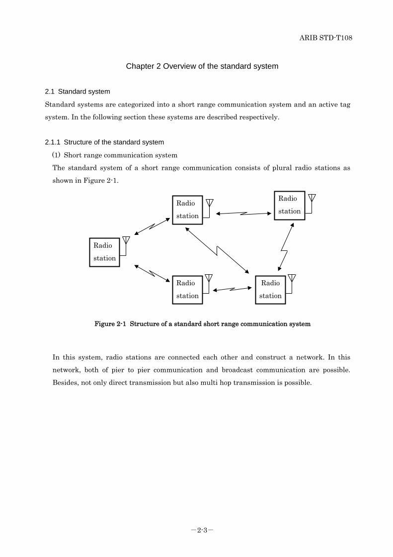
(1) Short range communication system
The standard system of a short range communication consists of plural radio stations as
shown in Figure 2-1.
Figure 2-1 Structure of a standard short range communication system
In this system, radio stations are connected each other and construct a network. In this
network, both of pier to pier communication and broadcast communication are possible.
Besides, not only direct transmission but also multi hop transmission is possible.
Radio
station Radio
station
Radio
station
Radio
station
Radio
station

ARIB STD-T108
-1-4-
(2) Active tag system
The standard system of active tags consists of a reader/writer and plural active tags as shown
in Figure 2-2.
Figure 2-2 Structure of a standard active tag system
In this system, one way or two way transmission between an active tag and a reader/writer
or between active tags in arbitrary timing is possible.
2.1.2 Operation of the standard system
(1) Short range communication system
Short range communication system is a short-range and low rate wireless PAN (Personal
Area Network) system with the purpose of low power consumption and low cost
implementation such as IEEE802.15.4 which is an existing standard in USA. As an
example of low rate wireless PAN system using IEEE802.15, there is Wi-SUN which is used
for Smart meter or various IoT (Internet of Things).
Recently, new various standards which can cover wide area with low power as LPWA (Low
Power Wide Area) are proposed and these standards are also included.
It is supposed to be used for home security, safety and security of children and elder people,
personal healthcare, home and building control, factory automation and monitoring, hospital
management, auto meter reading and outdoor monitoring on the network consisting of
wireless sensor nodes and/or wireless actuator nodes which control various kinds of
equipment
Reader/Writ
Active tag
Active tag Active tag
Active tag

ARIB STD-T108
-1-5-
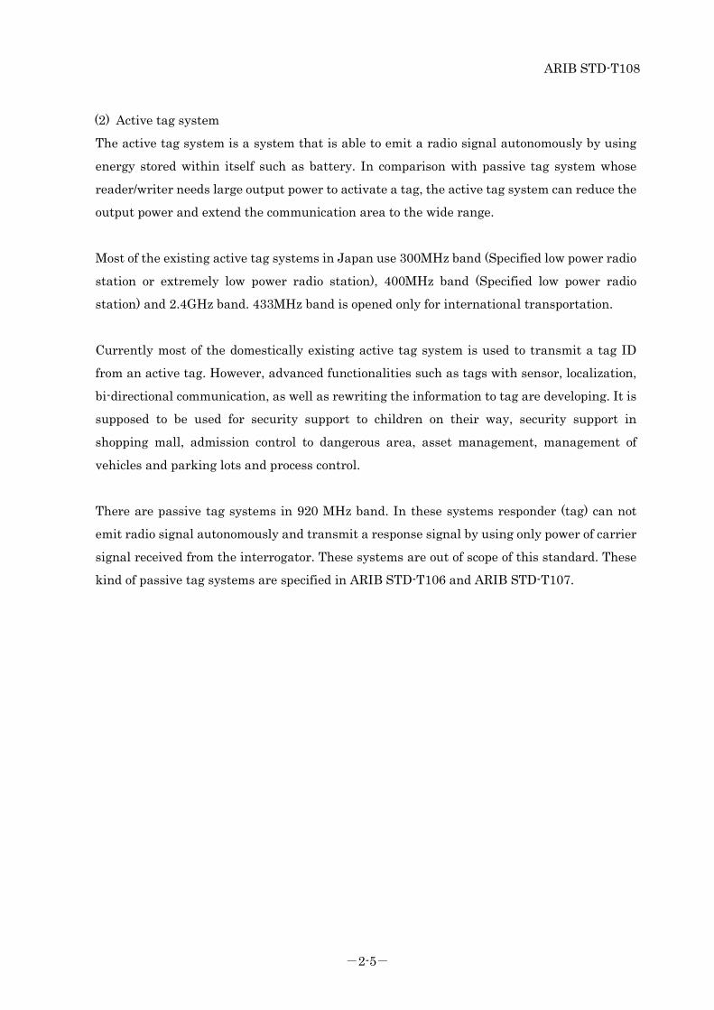
(2) Active tag system
The active tag system is a system that is able to emit a radio signal autonomously by using
energy stored within itself such as battery. In comparison with the passive tag system whose
reader/writer needs large output power to activate a tag, the active tag system can reduce the
output power and extend the communication area to the wide range.
Most of the existing active tag systems in Japan use 300MHz band (Specified low power radio
station or extremely low power radio station), 400MHz band (Specified low power radio
station) and 2.4GHz band. 433MHz band is opened only for international transportation use.
Currently most of the domestically existing active tag system is used to transmit a tag ID
from an active tag. However, advanced functionalities such as tags with sensor, localization,
bi-directional communication, as well as rewriting the information to tag are developing. It is
supposed to be used for security support to children on their way, security support in
shopping mall, admission control to dangerous area, asset management, management of
vehicles and parking lots and process control.
There are passive tag systems in 920MHz band. In these systems responder (tag) can not
emit radio signal autonomously and transmit a response signal by using only power of carrier
signal received from the interrogator. These systems are out of scope of this standard. These
kind of passive tag systems are specified in ARIB STD-T106 and ARIB STD-T107.
ARIB STD-T108
-1-6-
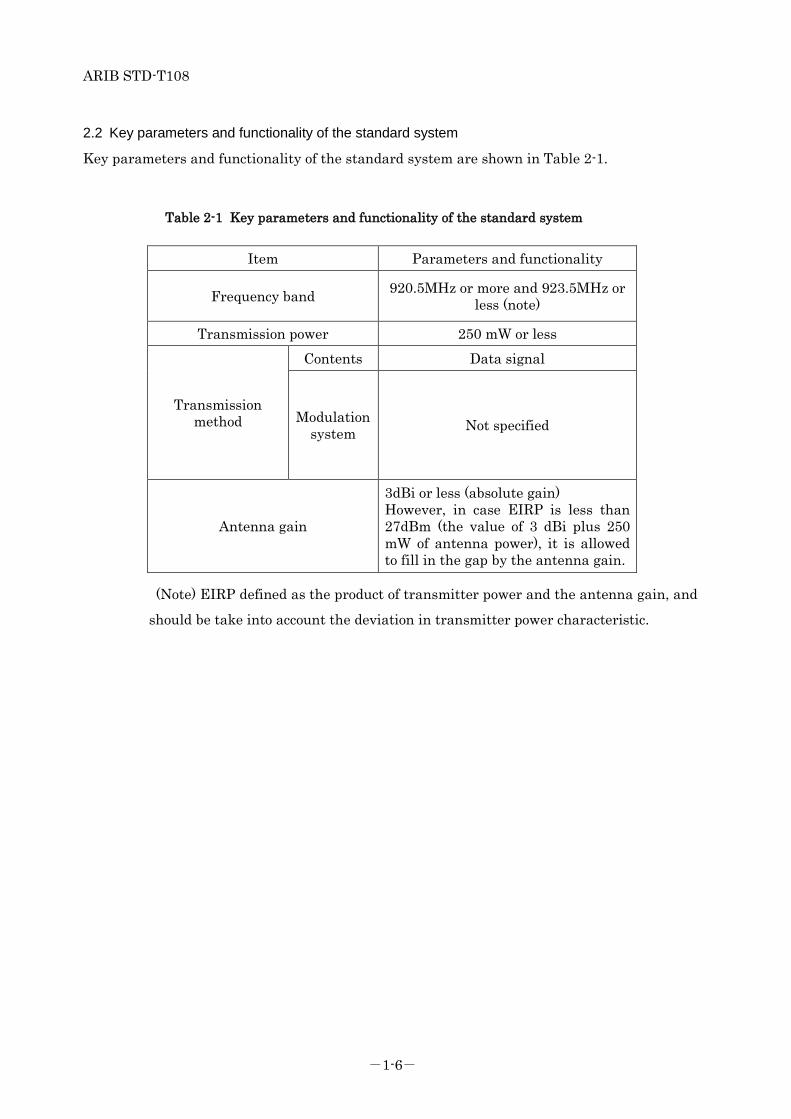
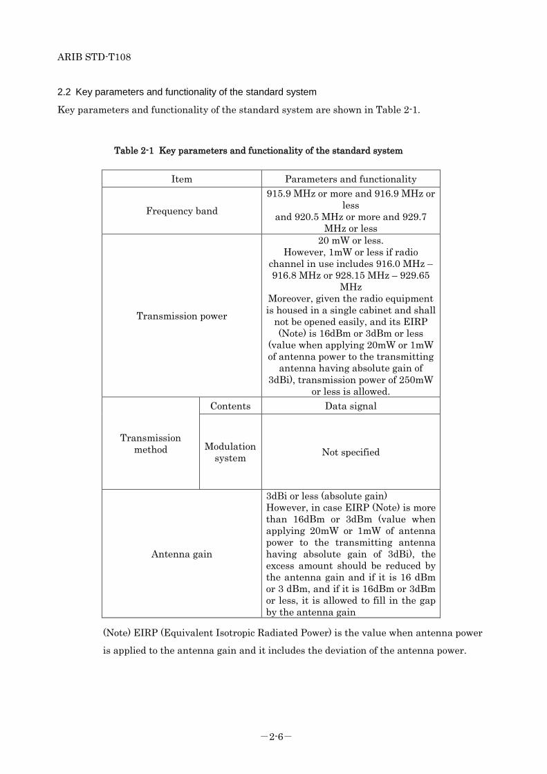
2.2 Key parameters and functionality of the standard system
Key parameters and functionality of the standard system are shown in Table 2-1.
Table 2-1 Key parameters and functionality of the standard system
Item Parameters and functionality
Frequency band 920.5MHz or more and 923.5MHz or less (note)
Transmission power 250 mW or less
Transmission method
Contents Data signal
Modulation system Not specified
Antenna gain
3dBi or less (absolute gain) However, in case EIRP is less than 27dBm (the value of 3 dBi plus 250 mW of antenna power), it is allowed to fill in the gap by the antenna gain.
(Note) EIRP defined as the product of transmitter power and the antenna gain, and
should be take into account the deviation in transmitter power characteristic.
ARIB STD-T108
-1-7-
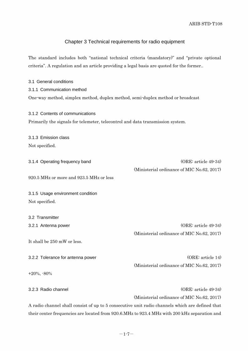
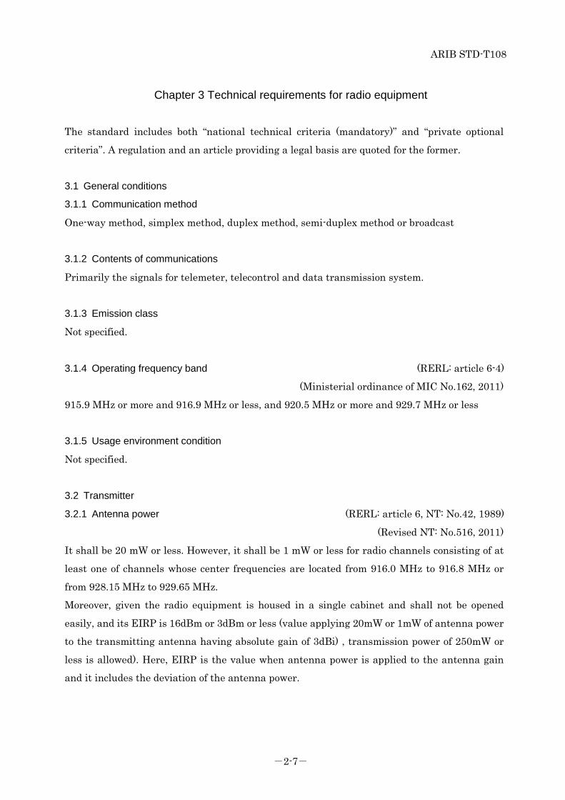
Chapter 3 Technical requirements for radio equipment
The standard includes both “national technical criteria (mandatory)” and “private optional
criteria”. A regulation and an article providing a legal basis are quoted for the former..
3.1 General conditions
3.1.1 Communication method
One-way method, simplex method, duplex method, semi-duplex method or broadcast
3.1.2 Contents of communications
Primarily the signals for telemeter, telecontrol and data transmission system.
3.1.3 Emission class
Not specified.
3.1.4 Operating frequency band (ORE: article 49-34)
(Ministerial ordinance of MIC No.62, 2017)
920.5 MHz or more and 923.5 MHz or less
3.1.5 Usage environment condition
Not specified.
3.2 Transmitter
3.2.1 Antenna power (ORE: article 49-34)
(Ministerial ordinance of MIC No.62, 2017)
It shall be 250 mW or less.
3.2.2 Tolerance for antenna power (ORE: article 14)
(Ministerial ordinance of MIC No.62, 2017)
+20%, -80%
3.2.3 Radio channel (ORE: article 49-34)
(Ministerial ordinance of MIC No.62, 2017)
A radio channel shall consist of up to 5 consecutive unit radio channels which are defined that
their center frequencies are located from 920.6.MHz to 923.4 MHz with 200 kHz separation and

ARIB STD-T108
-1-8-
their bandwidth are 200 kHz.
However, it is prohibited to simultaneously use both the unit radio channels giving priority to
passive tag system whose center frequencies are located from 920.6 MHz to 922.2 MHz
(Channel numbers are from 24 to 32) and the unit radio channels whose center frequencies are
located 922.4 MHz or more (Channel numbers are 33 or more)
The center frequencies of radio channels are shown through Table 3-1 to Table 3-5.
(1) The case of using one unit radio channel
Table 3-1 Center frequency of radio channel using one unit radio channel
(Bandwidth: 200 kHz)
Unit radio channel number
Center frequency (MHz)
Unit radio channel number
Center frequency (MHz)
24 920.6 32 922.2 25 920.8 33 922.4 26 921.0 34 922.6 27 921.2 35 922.8 28 921.4 36 923.0 29 921.6 37 923.2 30 921.8 38 923.4 31 922.0
(2) The case of using two unit radio channels
Table 3-2 Center frequency of radio channel using two unit radio channels
(Bandwidth:400 kHz)
Unit radio channel number
Center frequency (MHz)
Unit radio channel number
Center frequency (MHz)
24,25 920.7 31,32 922.1 25,26 920.9 33,34 922.5 26,27 921.1 34,35 922.7 27,28 921.3 35,36 922.9 28,29 921.5 36,37 923.1 29,30 921.7 37,38 923.3 30,31 921.9
(3) The case of using three unit radio channels
Table 3-3 Center frequency of radio channel using three unit radio channels
ARIB STD-T108
-1-9-
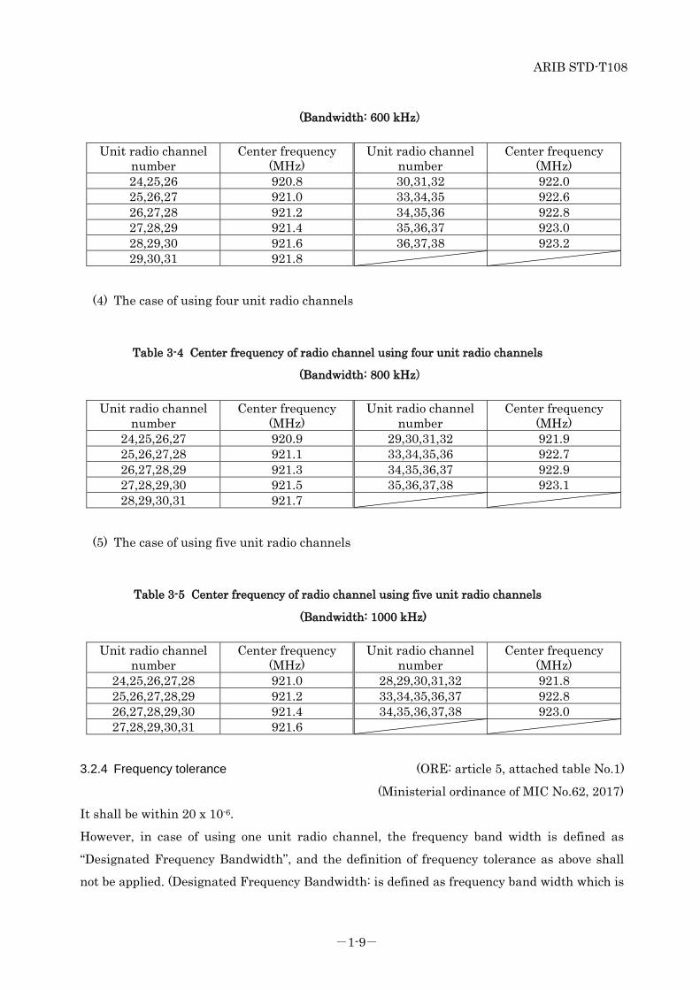
(Bandwidth: 600 kHz)
Unit radio channel number
Center frequency (MHz)
Unit radio channel number
Center frequency (MHz)
24,25,26 920.8 30,31,32 922.0 25,26,27 921.0 33,34,35 922.6 26,27,28 921.2 34,35,36 922.8 27,28,29 921.4 35,36,37 923.0 28,29,30 921.6 36,37,38 923.2 29,30,31 921.8
(4) The case of using four unit radio channels
Table 3-4 Center frequency of radio channel using four unit radio channels
(Bandwidth: 800 kHz)
Unit radio channel number
Center frequency (MHz)
Unit radio channel number
Center frequency (MHz)
24,25,26,27 920.9 29,30,31,32 921.9 25,26,27,28 921.1 33,34,35,36 922.7 26,27,28,29 921.3 34,35,36,37 922.9 27,28,29,30 921.5 35,36,37,38 923.1 28,29,30,31 921.7
(5) The case of using five unit radio channels
Table 3-5 Center frequency of radio channel using five unit radio channels
(Bandwidth: 1000 kHz)
Unit radio channel number
Center frequency (MHz)
Unit radio channel number
Center frequency (MHz)
24,25,26,27,28 921.0 28,29,30,31,32 921.8 25,26,27,28,29 921.2 33,34,35,36,37 922.8 26,27,28,29,30 921.4 34,35,36,37,38 923.0 27,28,29,30,31 921.6
3.2.4 Frequency tolerance (ORE: article 5, attached table No.1)
(Ministerial ordinance of MIC No.62, 2017)
It shall be within 20 x 10-6.
However, in case of using one unit radio channel, the frequency band width is defined as
“Designated Frequency Bandwidth”, and the definition of frequency tolerance as above shall
not be applied. (Designated Frequency Bandwidth: is defined as frequency band width which is
ARIB STD-T108
-1-10-
equal to the sum of allowable occupied frequency bandwidth and the twice of absolute frequency
bandwidth, under the condition that the center frequency of the designated frequency
bandwidth is equal to the center frequency of the radio channel.)
3.2.5 Modulation method
It shall not be specified.
3.2.6 Permissible value for occupied bandwidth (ORE: article 6, attached table No.2)
(Ministerial ordinance of MIC No.62, 2017)
It shall be (200 x n) kHz or less. (n is a number of unit radio channels constituting the radio
channel and is an integer from 1 to 5.)
ARIB STD-T108
-1-11-
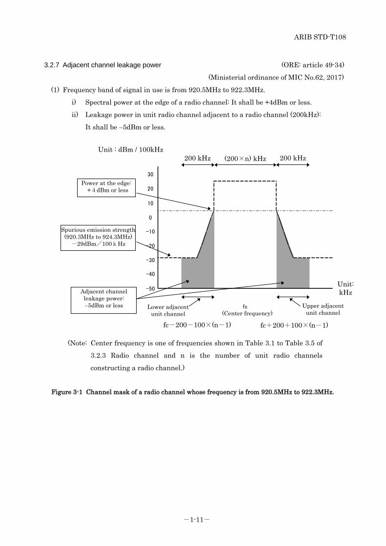
3.2.7 Adjacent channel leakage power (ORE: article 49-34)
(Ministerial ordinance of MIC No.62, 2017)
(1) Frequency band of signal in use is from 920.5MHz to 922.3MHz.
i) Spectral power at the edge of a radio channel: It shall be +4dBm or less.
ii) Leakage power in unit radio channel adjacent to a radio channel (200kHz):
It shall be –5dBm or less.
Figure 3-1 Channel mask of a radio channel whose frequency is from 920.5MHz to 922.3MHz.
Unit: kHz
200 kHz 200 kHz (200×n) kHz
Spurious emission strength (920.3MHz to 924.3MHz)
-29dBm/100kHz
Unit : dBm / 100kHz
Power at the edge: +4dBm or less
Adjacent channel leakage power: –5dBm or less
fc-200-100×(n-1)
Lower adjacent unit channel
Upper adjacent unit channel
fc+200+100×(n-1)
(Note: Center frequency is one of frequencies shown in Table 3.1 to Table 3.5 of
3.2.3 Radio channel and n is the number of unit radio channels
constructing a radio channel.)
-50
fc(中心周波数)
-20
-30
-40
0
-10
30
20
10
(Center frequency)
ARIB STD-T108
-1-12-
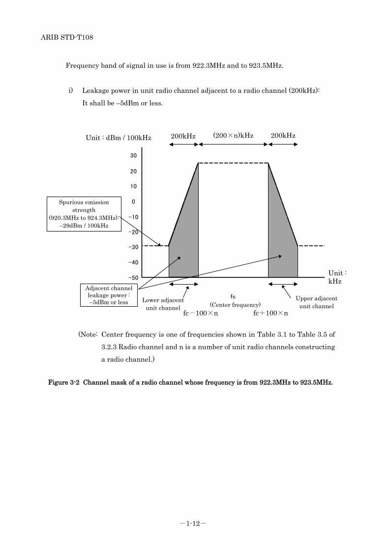
Frequency band of signal in use is from 922.3MHz and to 923.5MHz.
i) Leakage power in unit radio channel adjacent to a radio channel (200kHz):
It shall be –5dBm or less.
Figure 3-2 Channel mask of a radio channel whose frequency is from 922.3MHz to 923.5MHz.
(Note: Center frequency is one of frequencies shown in Table 3.1 to Table 3.5 of
3.2.3 Radio channel and n is a number of unit radio channels constructing
a radio channel.)
Adjacent channel leakage power : –5dBm or less
fc-100×n fc+100×n
Unit : dBm / 100kHz
Unit : kHz
Spurious emission strength
(920.3MHz to 924.3MHz): –29dBm / 100kHz
200kHz 200kHz (200×n)kHz
Upper adjacent unit channel
Lower adjacent unit channel
-50
fc(中心周波数)
10
20
30
0
-10
-40
-20
-30
(Center frequency)
ARIB STD-T108
-1-13-
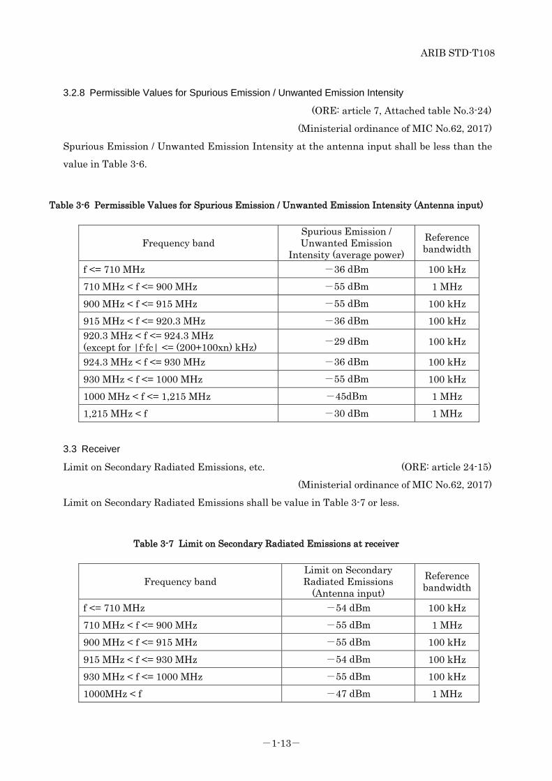
3.2.8 Permissible Values for Spurious Emission / Unwanted Emission Intensity
(ORE: article 7, Attached table No.3-24)
(Ministerial ordinance of MIC No.62, 2017)
Spurious Emission / Unwanted Emission Intensity at the antenna input shall be less than the
value in Table 3-6.
Table 3-6 Permissible Values for Spurious Emission / Unwanted Emission Intensity (Antenna input)
Frequency band Spurious Emission / Unwanted Emission
Intensity (average power) Reference bandwidth
f <= 710 MHz -36 dBm 100 kHz 710 MHz < f <= 900 MHz -55 dBm 1 MHz 900 MHz < f <= 915 MHz -55 dBm 100 kHz 915 MHz < f <= 920.3 MHz -36 dBm 100 kHz 920.3 MHz < f <= 924.3 MHz (except for |f-fc| <= (200+100xn) kHz) -29 dBm 100 kHz
924.3 MHz < f <= 930 MHz -36 dBm 100 kHz 930 MHz < f <= 1000 MHz -55 dBm 100 kHz 1000 MHz < f <= 1,215 MHz -45dBm 1 MHz 1,215 MHz < f -30 dBm 1 MHz
3.3 Receiver
Limit on Secondary Radiated Emissions, etc. (ORE: article 24-15)
(Ministerial ordinance of MIC No.62, 2017)
Limit on Secondary Radiated Emissions shall be value in Table 3-7 or less.
Table 3-7 Limit on Secondary Radiated Emissions at receiver
Frequency band Limit on Secondary Radiated Emissions
(Antenna input) Reference bandwidth
f <= 710 MHz -54 dBm 100 kHz 710 MHz < f <= 900 MHz -55 dBm 1 MHz 900 MHz < f <= 915 MHz -55 dBm 100 kHz 915 MHz < f <= 930 MHz -54 dBm 100 kHz 930 MHz < f <= 1000 MHz -55 dBm 100 kHz 1000MHz < f -47 dBm 1 MHz
ARIB STD-T108
-1-14-
3.4 Controller
Controller shall have functions that comply with the conditions specified in this section
described below.
3.4.1 Transmission time control equipment (ORE: article 49-34, NT: No.292, 2017)
(1) In case the 5ms or more carrier sense is required:
If the center frequency is from 920.6MHz to 923.4MHz, radio equipment shall stop its
emission of radio wave less than 4s after it starts to emit radio wave. It shall wait 50ms or
more for the consecutive emission.
Meanwhile, it may emit radio wave again without waiting 50ms, if the emission time is less
than 4s after its first emission, and this re-emission is started after 128µs or more carrier
sense, and is finished less than 4s after its first emission.
In case the center frequency is between 922.4MHz and 923.4MHz, the total transmission
time per an hour shall be 360 sec or less.
(2) In case the 128µs or more and less than 5ms carrier sense time is required:
If the center frequency is from 922.4MHz to 923.4MHz, the following conditions shall be
satisfied.
1. Using one unit radio channel: radio equipment shall stop its emission of radio wave less
than 400ms after it starts to emit radio wave. The sum of emission time per arbitrary one
hour shall be 360s or less.
Meanwhile, if the emission time is more than 200ms, it shall wait for ten times or more of
the former emission time. If the emission time is more than 6ms and is 200 ms or less, it shall
wait for 2ms for the consecutive emission.
In case the next emission is different from the previous center frequency channel, it is not
necessary to wait for ten times, and the next emission can be performed after 2ms of previous
emission.
2. Using two unit radio channels: radio equipment shall stop its emission of radio wave less
than 200ms after it starts to emit radio wave. The sum of emission time per arbitrary one
hour shall be 360s or less. Meanwhile if the emission time is more than 3ms, it shall wait for
2ms for the consecutive emission.
3. Using 3, 4, or 5 unit radio channels: radio equipment shall stop its emission of radio wave
less than 100ms after it starts to emit radio wave. The sum of emission time per arbitrary one
hour shall be 360s or less. Meanwhile if the emission time is more than 2ms, it shall wait 2ms
ARIB STD-T108
-1-15-
for the consecutive emission.
3.4.2 Carrier sense (ORE: article 49-34, NT: No.292, 2017)
(1) Radio equipment shall check if the interference exists by the career sense procedure
before its new transmission.
(2) Carrier sense time shall be 128 µs or more.
(3) Carrier sense level that is amount of received power at all of unit radio channels
included in the radio channel to emit shall be -80 dBm at the antenna input. When the
carrier sense level is not less than -80 dBm, radio equipment shall not transmit any
radio wave.
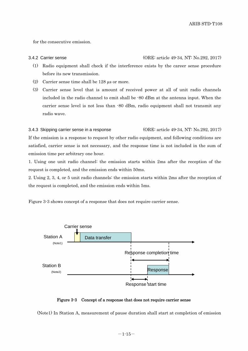
3.4.3 Skipping carrier sense in a response (ORE: article 49-34, NT: No.292, 2017)
If the emission is a response to request by other radio equipment, and following conditions are
satisfied, carrier sense is not necessary, and the response time is not included in the sum of
emission time per arbitrary one hour.
1. Using one unit radio channel: the emission starts within 2ms after the reception of the
request is completed, and the emission ends within 50ms.
2. Using 2, 3, 4, or 5 unit radio channels: the emission starts within 2ms after the reception of
the request is completed, and the emission ends within 5ms.
Figure 3-3 shows concept of a response that does not require carrier sense.
Figure 3-3 Concept of a response that does not require carrier sense
(Note1) In Station A, measurement of pause duration shall start at completion of emission
Station A (Note1)
Station B (Note2)
Data transfer
Response completion time
Response start time
Response
Carrier sense

ARIB STD-T108
-1-16-
at Station A.
(Note2) In Station B, measurement of pause duration shall start at completion of response
at Station B.
Table 3-8 shows possible combinations of sending control parameters specified by 3.4.1 Sending
control, 3.4.2 Carrier sense and 3.4.3 Skipping carrier sense in a response.
Table 3-8 Possible combinations of sending control parameters specified by 3.4.1 Sending control, 3.4.2
Carrier sense and 3.4.3 Skipping carrier sense in a response
Antenna power
Applied CH
number
Unit CH bandwidth
CH used in a
bundle
Carrier sense time
Sending duration
Pause duration
The sum of emission time per arbitrary
1 hour
Conditions of response to skip carrier sense (Note 2)
Completion time Start time
250mW or less
24-32 33-38
200kHz 1~5ch 5ms or
more 4s(Note1) 50ms 24-32:None
33-38:360sec or less
― ―
33-38 200kHz
1ch
128μs or more
More than 200ms, and
400ms or less
Ten times or more of the
former transmitting
time or 2ms (Note3)
360sec or less
50ms or less
2ms or less
More than 6ms, and
200ms or less 2ms
6ms or less None
2ch
More than 3ms, and
200ms or less 2ms
5ms or less 3ms or less None
3~5ch
More than 2ms, and
100ms or less 2ms
2ms or less None
(Note1) It may emit again without waiting 50ms, if it is within 4s after its first emission. The
emission shall start after carrier sense is performed for 128µs or more and the emission
shall finish within this 4s interval.
(Note2) Emission time of a response that satisfies the conditions is not included in the sum of
emission time per arbitrary one hour.
(Note3) Instead of ten times, 2ms can be applied in case the next emission is different center
frequency channel as the previous one.
3.4.4 Interference prevention function
The radio equipment shall automatically transmit/receive identification codes.

ARIB STD-T108
-1-17-
3.5 Cabinet (ORE: article 49-34)
(Ministerial ordinance of MIC No.62, 2017)
The high frequency circuit and modulation modules except for antenna shall be structured not
to be opened easily.
3.6 Connection to telecommunication circuit
(OCTF: article 9, NT: No.295, 2017)
Radio equipment shall satisfy the following conditions.
(1) It shall have identification code which shall be 32 bits length or more.
(2) Except for particular case which is defined outside of the specification, it shall make
decision if channel is used or not before using that channel. Only if that decision is "channel
is not used", it can set a communication path on its channel.
3.7 Antenna (ORE: article 49-34)
(Ministerial ordinance of MIC No.62, 2017)
Antenna gain 3dBi or less (absolute gain)
However, in case EIRP is less than 27dBm, it is allowed to fill in the gap
by the antenna gain.
EIRP defined as the product of transmitter power and the antenna gain,
and should be take into account the deviation in transmitter power
characteristic.

ARIB STD-T108
-1-18-
(Intentionally blanked)
ARIB STD-T108
-1-19-
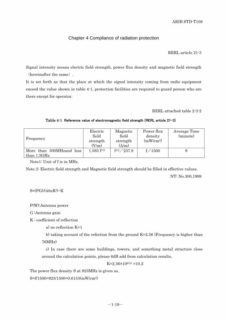
Chapter 4 Compliance of radiation protection
RERL article 21-3
Signal intensity means electric field strength, power flux density and magnetic field strength (hereinafter the same).
It is set forth as that the place at which the signal intensity coming from radio equipment
exceed the value shown in table 4-1, protection facilities are required to guard person who are
there except for operator.
RERL attached table 2-3-2
Table 4-1 Reference value of electromagnetic field strength (RERL article 21-3)
Frequency Electric
field strength
(V/m)
Magnetic field
strength (A/m)
Power flux density
(mW/cm2)
Average Time (minute)
More than 300MHzand less than 1.5GHz
1.585 f1/2 f1/2/237.8 f/1500 6
Note1: Unit of f is in MHz.
Note 2: Electric field strength and Magnetic field strength should be filled in effective values.
NT: No.300,1999
S=(PG)/(40πR2)・K
P(W):Antenna power
G :Antenna gain
K : coefficient of reflection
a) no reflection K=1
b) taking account of the refection from the ground K=2.56 (Frequency is higher than
76MHz)
c) In case there are some buildings, towers, and something metal structure close
around the calculation points, please 6dB add from calculation results.
K=2.56×10⁶/10 =10.2 The power flux density S at 923MHz is given as、
S=f/1500=923/1500=0.6153(mW/cm2)
ARIB STD-T108
-1-20-
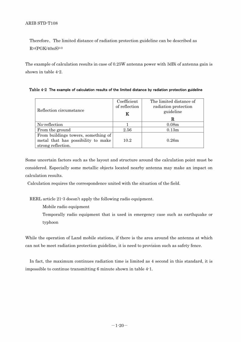
Therefore、The limited distance of radiation protection guideline can be described as
R=(PGK/40πS)1/2
The example of calculation results in case of 0.25W antenna power with 3dBi of antenna gain is
shown in table 4-2.
Table 4-2 The example of calculation results of the limited distance by radiation protection guideline
Reflection circumstance
Coefficient of reflection
K
The limited distance of radiation protection
guideline R
No-reflection 1 0.08m From the ground 2.56 0.13m From buildings towers, something of metal that has possibility to make strong reflection.
10.2 0.26m
Some uncertain factors such as the layout and structure around the calculation point must be
considered. Especially some metallic objects located nearby antenna may make an impact on
calculation results.
Calculation requires the correspondence united with the situation of the field.
RERL article 21-3 doesn’t apply the following radio equipment.
Mobile radio equipment
Temporally radio equipment that is used in emergency case such as earthquake or
typhoon
While the operation of Land mobile stations, if there is the area around the antenna at which
can not be meet radiation protection guideline, it is need to provision such as safety fence.
In fact, the maximum continues radiation time is limited as 4 second in this standard, it is
impossible to continue transmitting 6 minute shown in table 4-1.
ARIB STD-T108
-1-21-
Chapter 5 Measurement methods
TELEC-T258, which is established based on Notification No. 88-2 of MIC by Telecom
Engineering Center, shall be applied. If the other method is specified by Notification of MIC or
others, it shall be also applied.


ARIB STD-T108
Part 2 Specified low-power radio stations

ARIB STD-T108
-2-i-
Contents
Chapter 1 General items ............................................................................................................. 1
1.1 Overview ............................................................................................................................. 1
1.2 Scope of application ........................................................................................................... 1
1.3 Definitions of terminology ................................................................................................. 1
Chapter 2 Overview of the standard system ............................................................................. 3
2.1 Standard system ................................................................................................................ 3
2.1.1 Structure of the standard system .............................................................................. 3
2.1.2 Operation of the standard system .............................................................................. 4
2.2 Key parameters and functionality of the standard system ............................................ 6
Chapter 3 Technical requirements for radio equipment .......................................................... 7
3.1 General conditions ............................................................................................................. 7
3.1.1 Communication method .............................................................................................. 7
3.1.2 Contents of communications ...................................................................................... 7
3.1.3 Emission class ............................................................................................................. 7
3.1.4 Operating frequency band ...................................................................................... 7
3.1.5 Usage environment condition ..................................................................................... 7
3.2 Transmitter ........................................................................................................................ 7
3.2.1 Antenna power ......................................................................................................... 7
3.2.2 Tolerance for antenna power .................................................................................. 8
3.2.3 Radio channel ........................................................................................................... 8
3.2.4 Frequency tolerance .............................................................................................. 16
3.2.5 Modulation method ................................................................................................... 16
3.2.6 Permissible Value for Occupied Bandwidth ........................................................ 16
3.2.7 Adjacent channel leakage power .......................................................................... 17
3.2.8 Permissible Values for Spurious Emission / Unwanted Emission Intensity ........ 22
3.3 Receiver ............................................................................................................................ 23
3.4 Controller .......................................................................................................................... 23
3.4.1 Transmission time control equipment ............................................................. 23
3.4.2 Carrier sense .......................................................................................................... 25
3.4.3 Skipping carrier sense in a response .................................................................... 25
3.4.4 Interference prevention function .......................................................................... 28
3.5 Cabinet .............................................................................................................................. 28
3.6 Connection to telecommunication circuit ....................................................................... 28

ARIB STD-T108
-2-ii-
3.7 Antenna ............................................................................................................................ 28
Chapter 4 Measurement methods ......................................................................................... 29

ARIB STD-T108
-2-1-
Chapter 1 General items
1.1 Overview
Among the Specified Low-Power Radio Stations defined in Article 6 of the Regulations for
Enforcement of the Radio Law (Revision by Ministerial ordinance No. 65 of Ministry of Internal
Affairs and Communications, 2008) and Notification 42 of Ministry of Posts and
Telecommunications, 1989 (Revision by Notification 516 of Ministry of Internal Affairs and
Communications, 2011), this standard specifies on the telemeter, telecontrol and data
transmission radio equipment that uses the frequency of 915.9 MHz or more 929.7 MHz or less
specified in Article 49, Clause 14-7 and Clause 14-8 of Ordinance Regulating Radio Equipment
Regulations.
1.2 Scope of application
A telemeter, telecontrol and data transmission radio equipment consists of radio equipment,
data processing equipment and power supply equipment as shown in Figure 1-1. This standard
specifies the technical requirements of the radio equipment.
Figure 1-1 Structure of telemeter, telecontrol and data transmission radio equipment
1.3 Definitions of terminology
In this standard, ‘RL’ refers to the Radio Law, ‘RERL’ refers to the Regulations for Enforcement
of the Radio Law, ‘ORE’ refers to the Ordinance Regulating Radio Equipment, ‘OTRCC’ refers
Data processing
equipment
Power supply
equipment
Antenna
Radio equipment
Receiver
Transmitter
Control
equipment
Chassis
ARIB STD-T108
-2-2-
to the Ordinance Concerning Technical Regulations Conformity Certification etc. of Specified
Radio Equipment, ‘OCTF’ refers to the Ordinance Concerning Terminal Facilities Etc. and ‘NT’
refers to a Notification of the Ministry of Posts and Telecommunications before 2000 or a
Notification of the Ministry of Internal Affairs and Communications after 2001.
ARIB STD-T108
-2-3-
Chapter 2 Overview of the standard system 2.1 Standard system
Standard systems are categorized into a short range communication system and an active tag
system. In the following section these systems are described respectively.
2.1.1 Structure of the standard system
(1) Short range communication system
The standard system of a short range communication consists of plural radio stations as
shown in Figure 2-1.
Figure 2-1 Structure of a standard short range communication system
In this system, radio stations are connected each other and construct a network. In this
network, both of pier to pier communication and broadcast communication are possible.
Besides, not only direct transmission but also multi hop transmission is possible.
Radio
station
Radio
station
Radio
station
Radio
station
Radio
station

ARIB STD-T108
-2-4-
(2) Active tag system
The standard system of active tags consists of a reader/writer and plural active tags as shown
in Figure 2-2.
Figure 2-2 Structure of a standard active tag system
In this system, one way or two way transmission between an active tag and a reader/writer
or between active tags in arbitrary timing is possible.
2.1.2 Operation of the standard system
(1) Short range communication system
Short range communication system is a short-range and low rate wireless PAN (Personal
Area Network) system with the purpose of low power consumption and low cost
implementation such as IEEE802.15.4 which is an existing standard in USA.
Wi-SUN etc. used in smart meters and various IoT (Internet of Things) networks is as an
example of the low rate wireless PAN system using IEEE802.15.4.
Moreover, various standards have been proposed in recent years as LPWA (Low Power Wide
Area) having high coverage area at lower power consumption and these are also included as a
part of the short range communication system.
It is supposed to be used for home security, safety and security of children and elder people,
personal healthcare, home and building control, factory automation and monitoring, hospital
management, auto meter reading and outdoor monitoring on the network consisting of
wireless sensor nodes and/or wireless actuator nodes which control various kinds of
equipment
Reader/Writ
Active tag
Active tag
Active tag
Active tag
ARIB STD-T108
-2-5-
(2) Active tag system
The active tag system is a system that is able to emit a radio signal autonomously by using
energy stored within itself such as battery. In comparison with passive tag system whose
reader/writer needs large output power to activate a tag, the active tag system can reduce the
output power and extend the communication area to the wide range.
Most of the existing active tag systems in Japan use 300MHz band (Specified low power radio
station or extremely low power radio station), 400MHz band (Specified low power radio
station) and 2.4GHz band. 433MHz band is opened only for international transportation.
Currently most of the domestically existing active tag system is used to transmit a tag ID
from an active tag. However, advanced functionalities such as tags with sensor, localization,
bi-directional communication, as well as rewriting the information to tag are developing. It is
supposed to be used for security support to children on their way, security support in
shopping mall, admission control to dangerous area, asset management, management of
vehicles and parking lots and process control.
There are passive tag systems in 920 MHz band. In these systems responder (tag) can not
emit radio signal autonomously and transmit a response signal by using only power of carrier
signal received from the interrogator. These systems are out of scope of this standard. These
kind of passive tag systems are specified in ARIB STD-T106 and ARIB STD-T107.
ARIB STD-T108
-2-6-
2.2 Key parameters and functionality of the standard system
Key parameters and functionality of the standard system are shown in Table 2-1.
Table 2-1 Key parameters and functionality of the standard system
Item Parameters and functionality
Frequency band 915.9 MHz or more and 916.9 MHz or
less and 920.5 MHz or more and 929.7
MHz or less
Transmission power
20 mW or less. However, 1mW or less if radio
channel in use includes 916.0 MHz – 916.8 MHz or 928.15 MHz – 929.65
MHz Moreover, given the radio equipment is housed in a single cabinet and shall
not be opened easily, and its EIRP (Note) is 16dBm or 3dBm or less
(value when applying 20mW or 1mW of antenna power to the transmitting
antenna having absolute gain of 3dBi), transmission power of 250mW
or less is allowed.
Transmission method
Contents Data signal
Modulation system Not specified
Antenna gain
3dBi or less (absolute gain) However, in case EIRP (Note) is more than 16dBm or 3dBm (value when applying 20mW or 1mW of antenna power to the transmitting antenna having absolute gain of 3dBi), the excess amount should be reduced by the antenna gain and if it is 16 dBm or 3 dBm, and if it is 16dBm or 3dBm or less, it is allowed to fill in the gap by the antenna gain
(Note) EIRP (Equivalent Isotropic Radiated Power) is the value when antenna power
is applied to the antenna gain and it includes the deviation of the antenna power.
ARIB STD-T108
-2-7-
Chapter 3 Technical requirements for radio equipment
The standard includes both “national technical criteria (mandatory)” and “private optional
criteria”. A regulation and an article providing a legal basis are quoted for the former.
3.1 General conditions
3.1.1 Communication method
One-way method, simplex method, duplex method, semi-duplex method or broadcast
3.1.2 Contents of communications
Primarily the signals for telemeter, telecontrol and data transmission system.
3.1.3 Emission class
Not specified.
3.1.4 Operating frequency band (RERL: article 6-4)
(Ministerial ordinance of MIC No.162, 2011)
915.9 MHz or more and 916.9 MHz or less, and 920.5 MHz or more and 929.7 MHz or less
3.1.5 Usage environment condition
Not specified.
3.2 Transmitter
3.2.1 Antenna power (RERL: article 6, NT: No.42, 1989)
(Revised NT: No.516, 2011)
It shall be 20 mW or less. However, it shall be 1 mW or less for radio channels consisting of at
least one of channels whose center frequencies are located from 916.0 MHz to 916.8 MHz or
from 928.15 MHz to 929.65 MHz.
Moreover, given the radio equipment is housed in a single cabinet and shall not be opened
easily, and its EIRP is 16dBm or 3dBm or less (value applying 20mW or 1mW of antenna power
to the transmitting antenna having absolute gain of 3dBi) , transmission power of 250mW or
less is allowed). Here, EIRP is the value when antenna power is applied to the antenna gain
and it includes the deviation of the antenna power.
ARIB STD-T108
-2-8-
3.2.2 Tolerance for antenna power (ORE: article 14)
(Ministerial ordinance of MIC No.162, 2011)
+20%, -80%
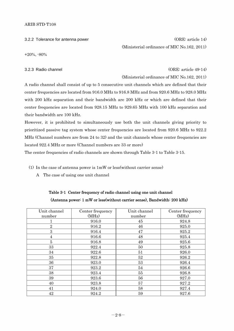
3.2.3 Radio channel (ORE: article 49-14)
(Ministerial ordinance of MIC No.162, 2011)
A radio channel shall consist of up to 5 consecutive unit channels which are defined that their
center frequencies are located from 916.0 MHz to 916.8 MHz and from 920.6 MHz to 928.0 MHz
with 200 kHz separation and their bandwidth are 200 kHz or which are defined that their
center frequencies are located from 928.15 MHz to 929.65 MHz with 100 kHz separation and
their bandwidth are 100 kHz.
However, it is prohibited to simultaneously use both the unit channels giving priority to
prioritized passive tag system whose center frequencies are located from 920.6 MHz to 922.2
MHz (Channel numbers are from 24 to 32) and the unit channels whose center frequencies are
located 922.4 MHz or more (Channel numbers are 33 or more)
The center frequencies of radio channels are shown through Table 3-1 to Table 3-15.
(1) In the case of antenna power is 1mW or less(without carrier sense)
A The case of using one unit channel
Table 3-1 Center frequency of radio channel using one unit channel
(Antenna power: 1 mW or less(without carrier sense), Bandwidth: 200 kHz)
Unit channel number
Center frequency (MHz)
Unit channel number
Center frequency (MHz)
1 916.0 45 924.8 2 916.2 46 925.0 3 916.4 47 925.2 4 916.6 48 925.4 5 916.8 49 925.6 33 922.4 50 925.8 34 922.6 51 926.0 35 922.8 52 926.2 36 923.0 53 926.4 37 923.2 54 926.6 38 923.4 55 926.8 39 923.6 56 927.0 40 923.8 57 927.2 41 924.0 58 927.4 42 924.2 59 927.6

ARIB STD-T108
-2-9-
43 924.4 60 927.8 44 924.6 61 928.0
Table 3-2 Center frequency of radio channel using one unit channel
(Antenna power: 1 mW or less(without carrier sense), Bandwidth: 100 kHz)
Unit channel number
Center frequency (MHz)
Unit channel number
Center frequency (MHz)
62 928.15 70 928.95 63 928.25 71 929.05 64 928.35 72 929.15 65 928.45 73 929.25 66 928.55 74 929.35 67 928.65 75 929.45 68 928.75 76 929.55 69 928.85 77 929.65
B The case of using two unit channels
Table 3-3 Center frequency of radio channel using two unit channels
(Antenna power: 1 mW or less(without carrier sense), Bandwidth: 400 kHz)
Unit channel number
Center frequency (MHz)
Unit channel number
Center frequency (MHz)
1,2 916.1 45,46 924.9 2,3 916.3 46,47 925.1 3,4 916.5 47,48 925.3 4,5 916.7 48,49 925.5
33,34 922.5 49,50 925.7 34,35 922.7 50,51 925.9 35,36 922.9 51,52 926.1 36,37 923.1 52,53 926.3 37,38 923.3 53,54 926.5 38,39 923.5 54,55 926.7 41,42 924.1 55,56 926.9 42,43 924.3 56,57 927.1 43,44 924.5 57,58 927.3 44,45 924.7 58,59 927.5 39,40 923.7 59,60 927.7 40,41 923.9 60,61 927.9

ARIB STD-T108
-2-10-
Table 3-4 Center frequency of radio channel using two unit channels
(Antenna power: 1 mW or less(without carrier sense), Bandwidth: 200 kHz)
Unit channel number
Center frequency (MHz)
Unit channel number
Center frequency (MHz)
62,63 928.2 70,71 929.0 63,64 928.3 71,72 929.1 64,65 928.4 72,73 929.2 65,66 928.5 73,74 929.3 66,67 928.6 74,75 929.4 67,68 928.7 75,76 929.5 68,69 928.8 76,77 929.6 69,70 928.9
C The case of using three unit channels
Table 3-5 Center frequency of radio channel using three unit channels
(Antenna power: 1mW or less(without carrier sense), Bandwidth: 600 kHz)
Unit channel number
Center frequency (MHz)
Unit channel number
Center frequency (MHz)
1,2,3 916.2 45,46,47 925.0 2,3,4 916.4 46,47,48 925.2 3,4,5 916.6 47,48,49 925.4
33,34,35 922.6 48,49,50 925.6 34,35,36 922.8 49,50,51 925.8 35,36,37 923.0 50,51,52 926.0 36,37,38 923.2 51,52,53 926.2 37,38,39 923.4 52,53,54 926.4 38,39,40 923.6 53,54,55 926.6 39,40,41 923.8 54,55,56 926.8 40,41,42 924.0 55,56,57 927.0 41,42,43 924.2 56,57,58 927.2 42,43,44 924.4 57,58,59 927.4 43,44,45 924.6 58,59,60 927.6 44,45,46 924.8 59,60,61 927.8

ARIB STD-T108
-2-11-
Table 3-6 Center frequency of radio channel using three unit channels
(Antenna power: 1mW or less(without carrier sense), Bandwidth: 300 kHz)
Unit channel number
Center frequency (MHz)
Unit channel number
Center frequency (MHz)
62,63,64 928.25 69,70,71 928.95 63,64,65 928.35 70,71,72 929.05 64,65,66 928.45 71,72,73 929.15 65,66,67 928.55 72,73,74 929.25 66,67,68 928.65 73,74,75 929.35 67,68,69 928.75 74,75,76 929.45 68,69,70 928.85 75,76,77 929.55
D The case of using four unit channels
Table 3-7 Center frequency of radio channel using four unit channels
(Antenna power: 1mW or less(without carrier sense), Bandwidth: 800 kHz)
Unit channel number
Center frequency (MHz)
Unit channel number
Center frequency (MHz)
1,2,3,4 916.3 45,46,47,48 925.1 2,3,4,5 916.5 46,47,48,49 925.3
33,34,35,36 922.7 47,48,49,50 925.5 34,35,36,37 922.9 48,49,50,51 925.7 35,36,37,38 923.1 49,50,51,52 925.9 36,37,38,39 923.3 50,51,52,53 926.1 37,38,39,40 923.5 51,52,53,54 926.3 38,39,40,41 923.7 52,53,54,55 926.5 39,40,41,42 923.9 53,54,55,56 926.7 40,41,42,43 924.1 54,55,56,57 926.9 41,42,43,44 924.3 55,56,57,58 927.1 42,43,44,45 924.5 56,57,58,59 927.3 43,44,45,46 924.7 57,58,59,60 927.5 44,45,46,47 924.9 58,59,60,61 927.7

ARIB STD-T108
-2-12-
Table 3-8 Center frequency of radio channel using four unit channels
(Antenna power: 1mW or less(without carrier sense), Bandwidth: 400 kHz)
Unit channel number
Center frequency (MHz)
Unit channel number
Center frequency (MHz)
62,63,64,65 928.3 69,70,71,72 929.0 63,64,65,66 928.4 70,71,72,73 929.1 64,65,66,67 928.5 71,72,73,74 929.2 65,66,67,68 928.6 72,73,74,75 929.3 66,67,68,69 928.7 73,74,75,76 929.4 67,68,69,70 928.8 74,75,76,77 929.5 68,69,70,71 928.9
E The case of using five unit channels
Table 3-9 Center frequency of radio channel using five unit channels
(Antenna power: 1mW or less(without carrier sense), Bandwidth: 1000 kHz)
Unit channel number Center frequency
(MHz)
Unit channel number Center frequency
(MHz) 1,2,3,4,5 916.4 45,46,47,48,49 925.2
33,34,35,36,37 922.8 46,47,48,49,50 925.4 34,35,36,37,38 923.0 47,48,49,50,51 925.6 35,36,37,38,39 923.2 48,49,50,51,52 925.8 36,37,38,39,40 923.4 49,50,51,52,53 926.0 37,38,39,40,41 923.6 50,51,52,53,54 926.2 38,39,40,41,42 923.8 51,52,53,54,55 926.4 39,40,41,42,43 924.0 52,53,54,55,56 926.6 40,41,42,43,44 924.2 53,54,55,56,57 926.8 41,42,43,44,45 924.4 54,55,56,57,58 927.0 42,43,44,45,46 924.6 55,56,57,58,59 927.2 43,44,45,46,47 924.8 56,57,58,59,60 927.4 44,45,46,47,48 925.0 57,58,59,60,61 927.6

ARIB STD-T108
-2-13-
Table 3-10 Center frequency of radio channel using five unit channels
(Antenna power: 1mW or less(without carrier sense), Bandwidth: 500 kHz)
Unit channel number
Center frequency (MHz)
Unit channel number
Center frequency (MHz)
62,63,64,65,66 928.35 68,69,70,71,72 928.95 63,64,65,66,67 928.45 69,70,71,72,73 929.05 64,65,66,67,68 928.55 70,71,72,73,74 929.15 65,66,67,68,69 928.65 71,72,73,74,75 929.25 66,67,68,69,70 928.75 72,73,74,75,76 929.35 67,68,69,70,71 928.85 73,74,75,76,77 929.45
(2) In the case of antenna power is 20mW or less(with carrier sense)
A The case of using one unit channel
Table 3-11 Center frequency of radio channel using one unit channel
(Antenna power: 20mW or less(with carrier sense), Bandwidth: 200 kHz)
Unit channel number
Center frequency (MHz)
Unit channel number
Center frequency (MHz)
24 920.6 43 924.4 25 920.8 44 924.6 26 921.0 45 924.8 27 921.2 46 925.0 28 921.4 47 925.2 29 921.6 48 925.4 30 921.8 49 925.6 31 922.0 50 925.8 32 922.2 51 926.0 33 922.4 52 926.2 34 922.6 53 926.4 35 922.8 54 926.6 36 923.0 55 926.8 37 923.2 56 927.0 38 923.4 57 927.2 39 923.6 58 927.4 40 923.8 59 927.6 41 924.0 60 927.8 42 924.2 61 928.0
ARIB STD-T108
-2-14-
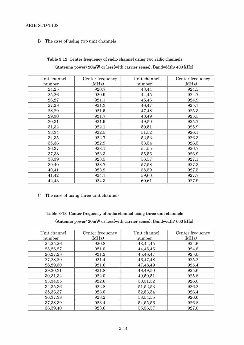
B The case of using two unit channels
Table 3-12 Center frequency of radio channel using two radio channels
(Antenna power: 20mW or less(with carrier sense), Bandwidth: 400 kHz)
Unit channel number
Center frequency (MHz)
Unit channel number
Center frequency (MHz)
24,25 920.7 43,44 924.5 25,26 920.9 44,45 924.7 26,27 921.1 45,46 924.9 27,28 921.3 46,47 925.1 28,29 921.5 47,48 925.3 29,30 921.7 48,49 925.5 30,31 921.9 49,50 925.7 31,32 922.1 50,51 925.9 33,34 922.5 51,52 926.1 34,35 922.7 52,53 926.3 35,36 922.9 53,54 926.5 36,37 923.1 54,55 926.7 37,38 923.3 55,56 926.9 38,39 923.5 56,57 927.1 39,40 923.7 57,58 927.3 40,41 923.9 58,59 927.5 41,42 924.1 59,60 927.7 42,43 924.3 60,61 927.9
C The case of using three unit channels
Table 3-13 Center frequency of radio channel using three unit channels
(Antenna power: 20mW or less(with carrier sense), Bandwidth: 600 kHz)
Unit channel number
Center frequency (MHz)
Unit channel number
Center frequency (MHz)
24,25,26 920.8 43,44,45 924.6 25,26,27 921.0 44,45,46 924.8 26,27,28 921.2 45,46,47 925.0 27,28,29 921.4 46,47,48 925.2 28,29,30 921.6 47,48,49 925.4 29,30,31 921.8 48,49,50 925.6 30,31,32 922.0 49,50,51 925.8 33,34,35 922.6 50,51,52 926.0 34,35,36 922.8 51,52,53 926.2 35,36,37 923.0 52,53,54 926.4 36,37,38 923.2 53,54,55 926.6 37,38,39 923.4 54,55,56 926.8 38,39,40 923.6 55,56,57 927.0

ARIB STD-T108
-2-15-
39,40,41 923.8 56,57,58 927.2 40,41,42 924.0 57,58,59 927.4 41,42,43 924.2 58,59,60 927.6 42,43,44 924.4 59,60,61 927.8
D The case of using four unit channels
Table 3-14 Center frequency of radio channel using four unit channels
(Antenna power: 20mW or less(with carrier sense), Bandwidth: 800 kHz)
Unit channel number
Center frequency (MHz)
Unit channel number
Center frequency (MHz)
24,25,26,27 920.9 43,44,45,46 924.7 25,26,27,28 921.1 44,45,46,47 924.9 26,27,28,29 921.3 45,46,47,48 925.1 27,28,29,30 921.5 46,47,48,49 925.3 28,29,30,31 921.7 47,48,49,50 925.5 29,30,31,32 921.9 48,49,50,51 925.7 33,34,35,36 922.7 49,50,51,52 925.9 34,35,36,37 922.9 50,51,52,53 926.1 35,36,37,38 923.1 51,52,53,54 926.3 36,37,38,39 923.3 52,53,54,55 926.5 37,38,39,40 923.5 53,54,55,56 926.7 38,39,40,41 923.7 54,55,56,57 926.9 39,40,41,42 923.9 55,56,57,58 927.1 40,41,42,43 924.1 56,57,58,59 927.3 41,42,43,44 924.3 57,58,59,60 927.5 42,43,44,45 924.5 58,59,60,61 927.7
E The case of using five unit channels
Table 3-15 Center frequency of radio channel using five unit channels
(Antenna power: 20mW or less(with carrier sense), Bandwidth: 1000 kHz)
Unit channel number
Center frequency (MHz)
Unit channel number
Center frequency (MHz)
24,25,26,27,28 921.0 43,44,45,46,47 924.8 25,26,27,28,29 921.2 44,45,46,47,48 925.0 26,27,28,29,30 921.4 45,46,47,48,49 925.2 27,28,29,30,31 921.6 46,47,48,49,50 925.4 28,29,30,31,32 921.8 47,48,49,50,51 925.6 33,34,35,36,37 922.8 48,49,50,51,52 925.8 34,35,36,37,38 923.0 49,50,51,52,53 926.0 35,36,37,38,39 923.2 50,51,52,53,54 926.2 36,37,38,39,40 923.4 51,52,53,54,55 926.4

ARIB STD-T108
-2-16-
37,38,39,40,41 923.6 52,53,54,55,56 926.6 38,39,40,41,42 923.8 53,54,55,56,57 926.8 39,40,41,42,43 924.0 54,55,56,57,58 927.0 40,41,42,43,44 924.2 55,56,57,58,59 927.2 41,42,43,44,45 924.4 56,57,58,59,60 927.4 42,43,44,45,46 924.6 57,58,59,60,61 927.6
3.2.4 Frequency tolerance (ORE: article 5, attached table No.1)
(NT: No.50, 1988)
(Revised NT: No.533, 2011)
It shall be within 20 x 10-6. However, above rule may not apply in case of using a single unit channel where the bandwidth
of the unit channel shall be the bandwidth of the designated frequency band. ("Designated
frequency band" means that the frequency at the center of the frequency band coincides with the
allocated frequency band and the frequency bandwidth is equal to the sum of the acceptance of
occupied frequency band width and twice the absolute value of the permissible deviation of the
frequency.)
3.2.5 Modulation method
It shall not be specified.
3.2.6 Permissible Value for Occupied Bandwidth (ORE: article 6, attached table No.2)
(NT: No.659, 2006)
(Revised NT: No.535, 2011)
It shall be (200 x n) kHz or less. However, in the case that the center frequency is from 928.15
MHz to 929.65 MHz, it shall be (100 x n) kHz or less. (n is a number of unit channels
constituting the radio channel and is an integer from 1 to 5.)
ARIB STD-T108
-2-17-
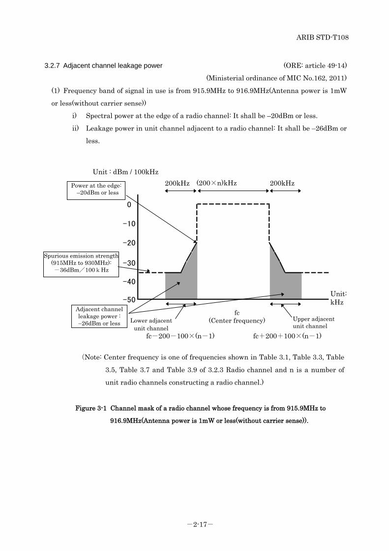
3.2.7 Adjacent channel leakage power (ORE: article 49-14)
(Ministerial ordinance of MIC No.162, 2011)
(1) Frequency band of signal in use is from 915.9MHz to 916.9MHz(Antenna power is 1mW
or less(without carrier sense))
i) Spectral power at the edge of a radio channel: It shall be –20dBm or less.
ii) Leakage power in unit channel adjacent to a radio channel: It shall be –26dBm or
less.
Figure 3-1 Channel mask of a radio channel whose frequency is from 915.9MHz to
916.9MHz(Antenna power is 1mW or less(without carrier sense)).
-50
-20
-30
-40
0
-10
(Note: Center frequency is one of frequencies shown in Table 3.1, Table 3.3, Table
3.5, Table 3.7 and Table 3.9 of 3.2.3 Radio channel and n is a number of
unit radio channels constructing a radio channel.)
Unit: kHz
Spurious emission strength (915MHz to 930MHz): -36dBm/100kHz
Unit : dBm / 100kHz 200kHz 200kHz (200×n)kHz
fc (Center frequency) Lower adjacent
unit channel Upper adjacent unit channel
fc-200-100×(n-1) fc+200+100×(n-1)
Adjacent channel leakage power : –26dBm or less
Power at the edge: –20dBm or less
ARIB STD-T108
-2-18-
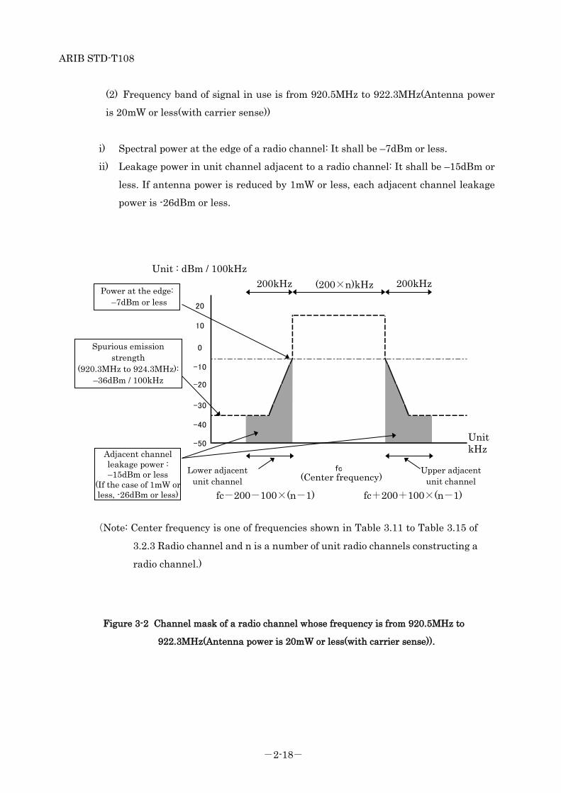
(2) Frequency band of signal in use is from 920.5MHz to 922.3MHz(Antenna power
is 20mW or less(with carrier sense))
i) Spectral power at the edge of a radio channel: It shall be –7dBm or less.
ii) Leakage power in unit channel adjacent to a radio channel: It shall be –15dBm or
less. If antenna power is reduced by 1mW or less, each adjacent channel leakage
power is -26dBm or less.
Figure 3-2 Channel mask of a radio channel whose frequency is from 920.5MHz to
922.3MHz(Antenna power is 20mW or less(with carrier sense)).
-50
fc(中心周波数)
20
-20
-30
-40
10
0
-10
Unit kHz
200kHz 200kHz (200×n)kHz
Spurious emission strength
(920.3MHz to 924.3MHz): –36dBm / 100kHz
Power at the edge: –7dBm or less
Adjacent channel leakage power : –15dBm or less
(If the case of 1mW or less, -26dBm or less) fc-200-100×(n-1) fc+200+100×(n-1)
Unit : dBm / 100kHz
Lower adjacent unit channel
Upper adjacent unit channel (Center frequency)
(Note: Center frequency is one of frequencies shown in Table 3.11 to Table 3.15 of
3.2.3 Radio channel and n is a number of unit radio channels constructing a
radio channel.)
ARIB STD-T108
-2-19-
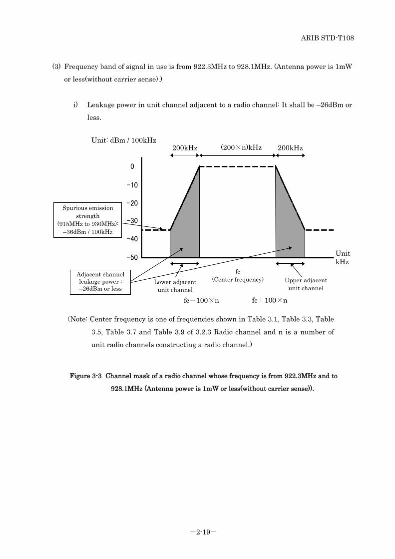
(3) Frequency band of signal in use is from 922.3MHz to 928.1MHz. (Antenna power is 1mW
or less(without carrier sense).)
i) Leakage power in unit channel adjacent to a radio channel: It shall be –26dBm or
less.
Figure 3-3 Channel mask of a radio channel whose frequency is from 922.3MHz and to
928.1MHz (Antenna power is 1mW or less(without carrier sense)).
-40
-50
-20
-30
-10
0
Unit kHz
Unit: dBm / 100kHz 200kHz 200kHz (200×n)kHz
fc (Center frequency)
fc-100×n fc+100×n
Lower adjacent unit channel
Upper adjacent unit channel
Adjacent channel leakage power : –26dBm or less
Spurious emission strength
(915MHz to 930MHz): –36dBm / 100kHz
(Note: Center frequency is one of frequencies shown in Table 3.1, Table 3.3, Table
3.5, Table 3.7 and Table 3.9 of 3.2.3 Radio channel and n is a number of
unit radio channels constructing a radio channel.)
ARIB STD-T108
-2-20-
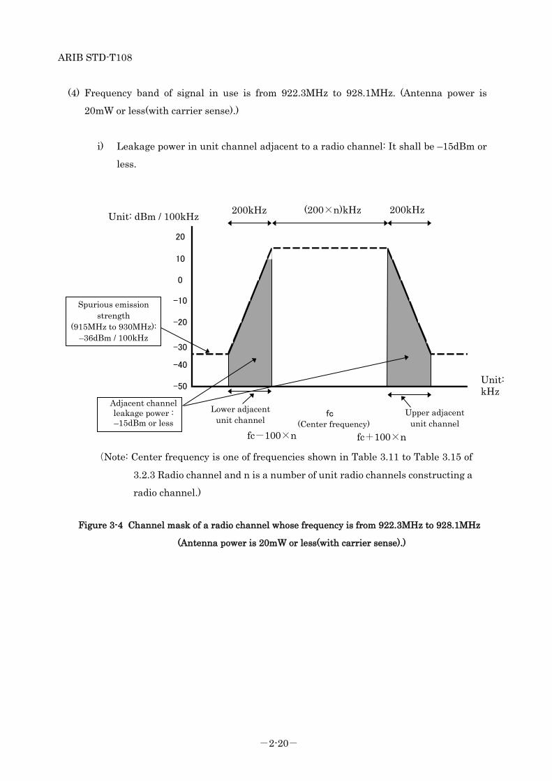
(4) Frequency band of signal in use is from 922.3MHz to 928.1MHz. (Antenna power is
20mW or less(with carrier sense).)
i) Leakage power in unit channel adjacent to a radio channel: It shall be –15dBm or
less.
Figure 3-4 Channel mask of a radio channel whose frequency is from 922.3MHz to 928.1MHz
(Antenna power is 20mW or less(with carrier sense).)
fc-100×n fc+100×n
Unit: dBm / 100kHz
Unit: kHz
200kHz 200kHz (200×n)kHz
Spurious emission strength
(915MHz to 930MHz): –36dBm / 100kHz
Adjacent channel leakage power : –15dBm or less
Lower adjacent unit channel
Upper adjacent unit channel
20
fc(中心周波数)
-40
-20
10
-50
0
-10
-30
(Center frequency)
(Note: Center frequency is one of frequencies shown in Table 3.11 to Table 3.15 of
3.2.3 Radio channel and n is a number of unit radio channels constructing a
radio channel.)
ARIB STD-T108
-2-21-
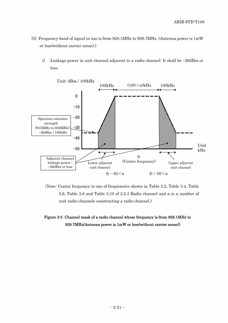
(5) Frequency band of signal in use is from 928.1MHz to 929.7MHz. (Antenna power is 1mW
or less(without carrier sense).)
i) Leakage power in unit channel adjacent to a radio channel: It shall be –26dBm or
less.
Figure 3-5 Channel mask of a radio channel whose frequency is from 928.1MHz to
929.7MHz(Antenna power is 1mW or less(without carrier sense))
-40
-50
-20
-30
-10
0
Unit kHz
Unit: dBm / 100kHz 100kHz 100kHz (100×n)kHz
fc (Center frequency)
fc-50×n fc+50×n
Lower adjacent unit channel
Upper adjacent unit channel
Spurious emission strength
(915MHz to 930MHz): –36dBm / 100kHz
Adjacent channel leakage power : –26dBm or less
(Note: Center frequency is one of frequencies shown in Table 3.2, Table 3.4, Table
3.6, Table 3.8 and Table 3.10 of 3.2.3 Radio channel and n is a number of
unit radio channels constructing a radio channel.)

ARIB STD-T108
-2-22-
3.2.8 Permissible Values for Spurious Emission / Unwanted Emission Intensity
(ORE: article 7, Attached table No.3-25)
(Ministerial ordinance of MIC No.162, 2011)
Permissible Values for Spurious Emission / Unwanted Emission Intensity at the antenna input
shall be less than the value in Table 3-16.
Table 3-16 Permissible Values for Spurious Emission / Unwanted Emission Intensity (Antenna input)
Frequency band Spurious emission /
Unwanted Emission Intensity (average power)
Reference bandwidth
f <= 710 MHz -36 dBm 100 kHz 710 MHz < f <= 900 MHz -55 dBm 1M Hz 900 MHz < f <= 915 MHz -55 dBm 100 kHz 915 MHz < f <= 930 MHz (Except for |f-fc| <= (200+100×n) kHz
if bandwidth of unit channel is 200 kHz, except for |f-fc| <= (100+50×n) kHz if bandwidth of unit channel is 100 kHz.
Except for |f-fc| <= (100+100×n)kHz if frequency band is 915.9MHz <= f <= 916.9MHz and 920.5MHz <= 922.3MHz. Where n is a number of unit channels
constituting the radio channel and is an integer from 1 to 5)
-36 dBm 100 kHz
930 MHz < f <= 1000 MHz -55 dBm 100 kHz 1000MHz < f <= 1,215 MHz -45 dBm 1M Hz 1,215 MHz < f -30 dBm 1M Hz
ARIB STD-T108
-2-23-
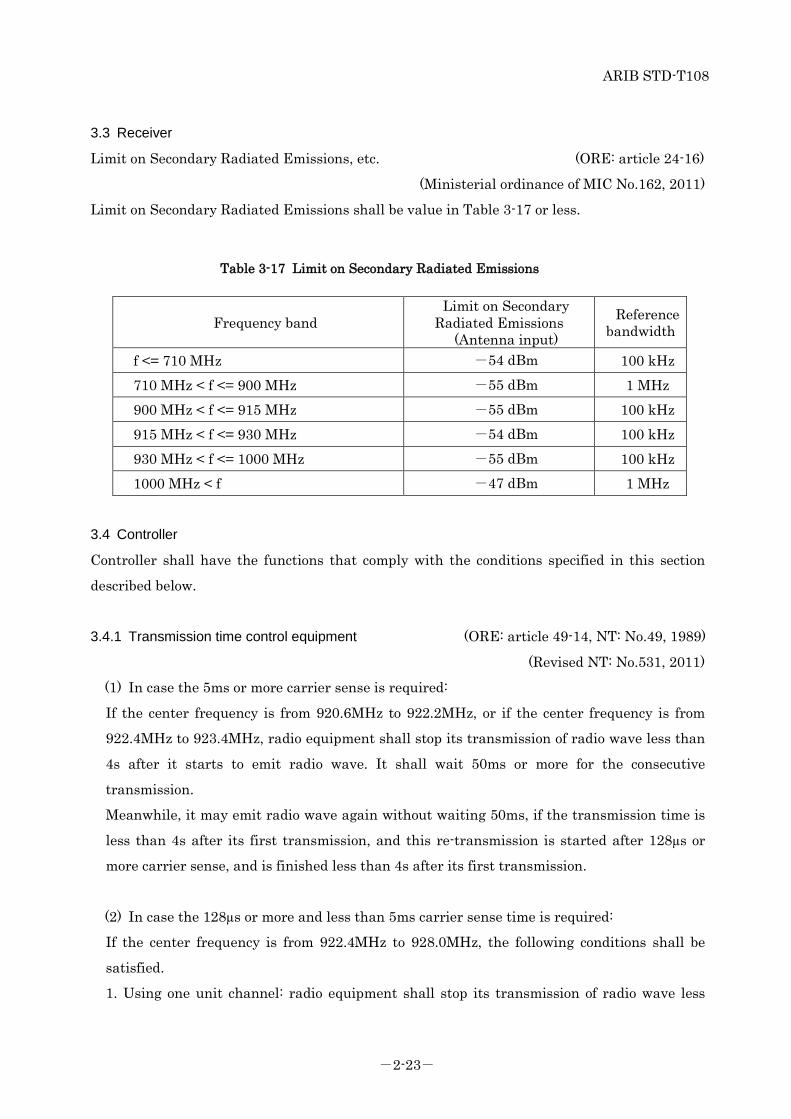
3.3 Receiver
Limit on Secondary Radiated Emissions, etc. (ORE: article 24-16)
(Ministerial ordinance of MIC No.162, 2011)
Limit on Secondary Radiated Emissions shall be value in Table 3-17 or less.
Table 3-17 Limit on Secondary Radiated Emissions
Frequency band Limit on Secondary
Radiated Emissions (Antenna input)
Reference bandwidth
f <= 710 MHz -54 dBm 100 kHz 710 MHz < f <= 900 MHz -55 dBm 1 MHz 900 MHz < f <= 915 MHz -55 dBm 100 kHz 915 MHz < f <= 930 MHz -54 dBm 100 kHz 930 MHz < f <= 1000 MHz -55 dBm 100 kHz 1000 MHz < f -47 dBm 1 MHz
3.4 Controller
Controller shall have the functions that comply with the conditions specified in this section
described below.
3.4.1 Transmission time control equipment (ORE: article 49-14, NT: No.49, 1989)
(Revised NT: No.531, 2011)
(1) In case the 5ms or more carrier sense is required:
If the center frequency is from 920.6MHz to 922.2MHz, or if the center frequency is from
922.4MHz to 923.4MHz, radio equipment shall stop its transmission of radio wave less than
4s after it starts to emit radio wave. It shall wait 50ms or more for the consecutive
transmission.
Meanwhile, it may emit radio wave again without waiting 50ms, if the transmission time is
less than 4s after its first transmission, and this re-transmission is started after 128µs or
more carrier sense, and is finished less than 4s after its first transmission.
(2) In case the 128µs or more and less than 5ms carrier sense time is required:
If the center frequency is from 922.4MHz to 928.0MHz, the following conditions shall be
satisfied.
1. Using one unit channel: radio equipment shall stop its transmission of radio wave less
ARIB STD-T108
-2-24-
than 400ms after it starts to emit radio wave. The sum of transmission time per arbitrary one
hour shall be 360s or less.
Meanwhile, if the transmission time is more than 6ms and is 200ms or less, it shall wait for
2ms for the consecutive transmission. If the transmission time is more than 200ms, it shall
wait for ten times or more of the former transmission time. When a transmission using
different center frequency is used after the previous transmission is completed, transmission
in a different frequency channel is allowed after 2ms of the completion of transmission in the
former channel without waiting for ten times or more of the former transmission time.
2. Using two unit channels: radio equipment shall stop its transmission of radio wave less
than 200ms after it starts to emit radio wave. The sum of transmission time per arbitrary one
hour shall be 360s or less. Meanwhile if the transmission time is more than 3ms, it shall wait
for 2ms for the consecutive transmission.
3. Using 3, 4, or 5 unit channels: radio equipment shall stop its transmission of radio wave
less than 100ms after it starts to emit radio wave. The sum of transmission time per
arbitrary one hour shall be 360s or less. Meanwhile if the transmission time is more than
2ms, it shall wait 2ms for the consecutive transmission.
(3) In case non carrier sense is required:
The following conditions shall be satisfied.
1. If the center frequency is from 916.0MHz to 916.8MHz, or from 922.4MHz to 928.0MHz,
and the antenna power is 1mW or less, radio equipment shall stop its transmission of radio
wave less than 100ms after it starts to emit radio wave. It shall wait 100ms or more for the
consecutive transmission. The sum of transmission time per arbitrary one hour shall be 3.6s
or less.
Meanwhile, it may emit radio wave again without waiting 100ms, if the transmission time
less than 100ms after its first transmission
2. If the center frequency is from 928.15MHz to 929.65MHz, radio equipment shall stop its
transmission of radio wave less than 50ms after it starts to emit radio wave. It shall wait
50ms or more for the consecutive transmission.
Meanwhile, it may emit radio wave again without waiting 50ms, if the transmission time is
less than 50ms after its first transmission and the re-transmission is finished less than 50ms
after its first transmission.

ARIB STD-T108
-2-25-
3.4.2 Carrier sense (ORE: article 49-14, NT: No.49, 1988)
(Revised NT: No.531, 2011)
(1) Radio equipment shall check if the interference exists by the career sense procedure
before its new transmission.
(2) Carrier sense time shall be 128µs or more.
(3) Carrier sense level, amount of received power at all of unit channels included in the
radio channel to emit, shall be -80dBm at the antenna input. When the carrier sense
level is more than -80dBm, radio equipment shall not emit any radio wave. However, in
case were transmission power exceeds 20mW, the carrier sense level shall be further
deduced from -80dBm by the exceeding power above 20mW.
(4) Carrier sense is not necessary if the antenna power is 1mW or less and the conditions of
3.4.1 (3) are satisfied
3.4.3 Skipping carrier sense in a response (ORE: article 49-14, NT: No.49, 1989)
(Revised NT: No.531, 2011)
If the transmission is a response to request by other radio equipment, and following conditions
are satisfied, carrier sense is not necessary, and the response time is not included in the sum of
transmission time per arbitrary one hour.
1. Using one unit channel: the transmission starts within 2ms after the reception of the
request is completed, and the transmission ends within 50ms after the reception of the request
is completed.
2. Using 2, 3, 4, or 5 unit channels: the transmission starts within 2ms after the reception of
the request is completed, and the transmission ends within 5ms after the reception of the
request is completed.
Figure 3-6 shows concept of a response that does not require carrier sense.

ARIB STD-T108
-2-26-
Figure 3-6 Concept of a response that does not require carrier sense
(Note1) In Station A, measurement of pause duration shall start at completion of
transmission at Station A.
(Note2) In Station B, measurement of pause duration shall start at completion of response
at Station B.
Station A (Note1)
Station B (Note2)
Data transfer
Response completion time
Response start time
Response
Carrier sense
ARIB STD-T108
-2-27-
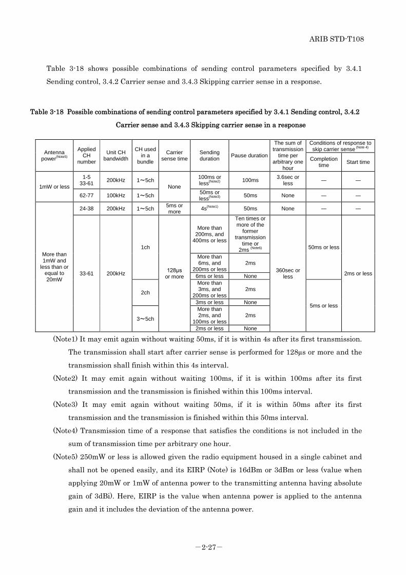
Table 3-18 shows possible combinations of sending control parameters specified by 3.4.1
Sending control, 3.4.2 Carrier sense and 3.4.3 Skipping carrier sense in a response.
Table 3-18 Possible combinations of sending control parameters specified by 3.4.1 Sending control, 3.4.2
Carrier sense and 3.4.3 Skipping carrier sense in a response
Antenna power(Note5)
Applied CH
number
Unit CH bandwidth
CH used in a
bundle
Carrier sense time
Sending duration Pause duration
The sum of transmission
time per arbitrary one
hour
Conditions of response to skip carrier sense (Note 4)
Completion time Start time
1mW or less
1-5 33-61 200kHz 1~5ch
None
100ms or less(Note2) 100ms 3.6sec or
less ― ―
62-77 100kHz 1~5ch 50ms or less(Note3) 50ms None ― ―
More than 1mW and
less than or equal to 20mW
24-38 200kHz 1~5ch 5ms or more 4s(Note1) 50ms None ― ―
33-61 200kHz
1ch
128μs or more
More than 200ms, and
400ms or less
Ten times or more of the
former transmission
time or 2ms (Note6)
360sec or less
50ms or less
2ms or less
More than 6ms, and
200ms or less 2ms
6ms or less None
2ch
More than 3ms, and
200ms or less 2ms
5ms or less 3ms or less None
3~5ch
More than 2ms, and
100ms or less 2ms
2ms or less None
(Note1) It may emit again without waiting 50ms, if it is within 4s after its first transmission.
The transmission shall start after carrier sense is performed for 128µs or more and the
transmission shall finish within this 4s interval.
(Note2) It may emit again without waiting 100ms, if it is within 100ms after its first
transmission and the transmission is finished within this 100ms interval.
(Note3) It may emit again without waiting 50ms, if it is within 50ms after its first
transmission and the transmission is finished within this 50ms interval.
(Note4) Transmission time of a response that satisfies the conditions is not included in the
sum of transmission time per arbitrary one hour.
(Note5) 250mW or less is allowed given the radio equipment housed in a single cabinet and
shall not be opened easily, and its EIRP (Note) is 16dBm or 3dBm or less (value when
applying 20mW or 1mW of antenna power to the transmitting antenna having absolute
gain of 3dBi). Here, EIRP is the value when antenna power is applied to the antenna
gain and it includes the deviation of the antenna power.

ARIB STD-T108
-2-28-
(Note6) When a transmission using different center frequency is used after the previous
transmission is completed, transmission in a different frequency channel is allowed after
2ms of the completion of transmission in the former channel without waiting for ten
times or more of the former transmission time.
3.4.4 Interference prevention function (RL: article 4-3, RERL: article 6-2)
The radio equipment shall automatically transmit/receive identification codes.
3.5 Cabinet (ORE: article 49-14)
(Ministerial ordinance of MIC No.66, 2008)
The high frequency circuit and modulation modules except for antenna shall be structured not
to be opened easily.
3.6 Connection to telecommunication circuit
(OCTF: article 9, NT: No.424, 1994)
Radio equipment shall satisfy the following conditions.
(1) It shall have identification code which shall be 32 bits length or more.
(2) Except for particular case which is defined outside of the specification, it shall make
decision if channel is used or not before using that channel. Only if that decision is "channel
is not used", it can set a communication path on its channel.
3.7 Antenna (ORE: article 49-14)
(Ministerial ordinance of MIC No.66, 2008)
Antenna gain 3dBi or less (absolute gain)
However, in case EIRP is more than 16dBm or 3dBm (value when
applying the antenna power set forth in 3.2(1) to the transmitting
antenna having absolute gain of 3dBi), the excess amount should be
reduced by the antenna gain, and if it is 16dBm or 3dBm or less, it is
allowed to fill in the gap by the antenna gain. Here, EIRP is the value
when antenna power is applied to the antenna gain and it includes the
deviation of the antenna power.
ARIB STD-T108
-2-29-
Chapter 4 Measurement methods
TELEC-T245, which is established based on Notification No. 88-2 of MIC by Telecom
Engineering Center, shall be applied. If the other method is specified by Notification of MIC or
others, it shall be also applied.


ARIB STD-T108
Appendix Operational rule


ARIB STD-T108
-3-i-
Contents
1 Overview .................................................................................................................................... 1
1.1 Purpose ............................................................................................................................... 1
1.2 Scope of Application ........................................................................................................... 1
1.3 Target Systems .................................................................................................................. 1
2 Interference Avoidance Method ............................................................................................... 1
2.1 Channel Assignment ......................................................................................................... 1
2.1.1 915.9 MHz to 916.9 MHz ............................................................................................ 1
2.1.2 920.5 MHz to 922.3 MHz ............................................................................................ 1
2.1.3 922.3 MHz to 929.7 MHz ............................................................................................ 2
2.2 Interference to aeronautical radio systems ..................................................................... 2
2.3 Coexistence to systems using different carrier sense times ........................................... 2
2.4 Recommended operating Practice for 250mW category stations ................................... 3
2.4.1 Interference mitigation ............................................................................................... 3
2.4.2 Interconnection with specified low-power radio stations ......................................... 4
2.5 Implementing functionality of frequency channel switch............................................... 4
3 Influence to medical equipment .............................................................................................. 4
4 Protection of privacy ................................................................................................................. 4
5 Radio equipment operates under multiple provisions ........................................................... 5
5.1 Type of provision ................................................................................................................ 5
5.2 Radio equipment specified in this chapter ....................................................................... 5
5.3 Operation of the equipment .............................................................................................. 5
5.3.1 The principle of operation ........................................................................................... 5
5.3.2 Clear indication of operation of equipment ............................................................... 6
5.3.3 The example of operating equipment ........................................................................ 6
5.3.4 Equipment operated by changing conditions under the same provision ................ 7
6 Changes on revision up ............................................................................................................ 8
6.1 Updates from ARIB STD-T96 to ARIB STD-T108 v1.0 .................................................. 8
6.1.1 Improvement of usability for active tag system ........................................................ 8
6.1.2 Sharing with passive tag systems .............................................................................. 8
6.1.3 Antenna power ............................................................................................................ 9
6.2 Updates from ARIB STD-T108 v1.0 to ARIB STD-T108 v1.1 ...................................... 10
6.2.1 Use of narrow band frequency .................................................................................. 10
6.2.2 Revise of 1mW and 20mW stations ......................................................................... 10
ARIB STD-T108
-3-ii-
6.2.3 Adoption of EIRP method ......................................................................................... 11
6.3 Updates from ARIB STD-T108 v1.1 to ARIB STD-T108 v1.2 ...................................... 13
7 Channel plan for 920MHz-band radio equipment ............................................................... 15

ARIB STD-T108
-3-1-
Appendix Operational rule
1 Overview
1.1 Purpose
These guidelines aim to avoid undesired interference to other neighboring wireless systems,
to effectively utilize frequency resource and to guarantee user’s convenience when a user
operates 920 MHz-band convenience radio stations or specified low-power radio stations for
telemeter, telecontrol and data transmission (these are abbreviated to “convenience radio
stations” and “specified low-power radio stations” respectively in the following sentences).
1.2 Scope of Application
These guidelines are directed to users, manufacturers, sellers, constructors, operators and
maintenance persons.
1.3 Target Systems
These guidelines target following systems: 920 MHz-band telemeter, telecontrol and data
transmission radio equipment (ARIB STD-T108).
2 Interference Avoidance Method
2.1 Channel Assignment
Radio stations targeted in this standard shares 920 MHz-band with STD-T106
(920MHz-band RFID equipment for premises radio station) or STD-T107 (920MHz-band RFID
equipment for specified low power radio station) radio stations. In an effort to avoid
interference with those radio stations, this standard specifies the following channel
assignment.
2.1.1 915.9 MHz to 916.9 MHz
Internationally circulating radio stations with its antenna power 1 mW or less shall
exclusively use this band.
2.1.2 920.5 MHz to 922.3 MHz
As is described in Part I 3.4.1-(1) and Part II 3.4.1-(1), radio stations shall conform to the
technical rules specified in STD-T106 (high power passive tag readers) and STD-T107 (low
power passive tag readers), and in addition, shall conduct carrier sense for 128 µs or more

ARIB STD-T108
-3-2-
before retransmission even if that retransmission is within 4 s after having completed carrier
sense for not less than 5ms. If a radio station uses a portion of this band as part of the bundled
unit channels, it shall also conform to the rules specified above.
2.1.3 922.3 MHz to 929.7 MHz
Radio stations must conform to the rules specified in Part I 3.4.1-(2) and Part II 3.4.1-(2) of
this standard.
2.2 Interference to aeronautical radio systems
Electronic equipment that is prohibited from being activated on aircraft to maintain the safety
of aircraft pursuant to the provisions of Civil Aeronautics Act which falls under the radio
stations specified in this standard shall have either of the following structures if it is to be
carried on aircraft:
• The equipment shall be deactivated by removing the batteries or being switched off
• The equipment shall have a structure such that it cannot be activated without being
switched on.
However, it is not necessary for radio equipment assessed using the test procedures described
in DO-294 published by the RTCA and confirmed to be free from the risk of interference to have
the above-mentioned structures.
Related laws and regulations
• Civil Aeronautics Act Article 73-4
• Ordinance for Enforcement of the Civil Aeronautics Act Article 164-15 Safety impending acts
• Notification No. 1346 of Ministry of Land, Infrastructure, Transport and Tourism (2003): Devices prohibited for use at all times
2.3 Coexistence to systems using different carrier sense times
As specified in this standard, there are two types of radio stations in the 920MHz- band;
short CS stations using carrier sense time of 128 µs or more and long CS stations using carrier
sense time of 5ms or more. Short CS stations are efficient to have low power consumption with
batteries, by means of short data communication with long duration. In this standard, total
transmission time of short CS stations shall be 10% or less of duration.
However, as shown in Fig. S-1, there is a possibility that short CS stations within an
interference range, in which they affect their carrier senses each other, periodically repeat data
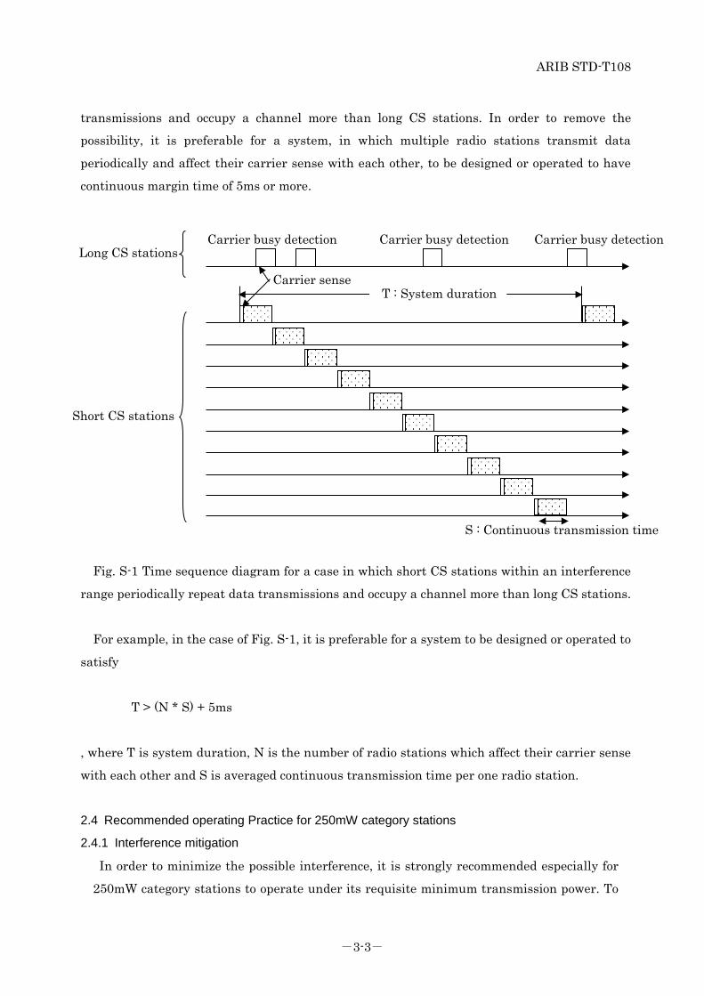
ARIB STD-T108
-3-3-
transmissions and occupy a channel more than long CS stations. In order to remove the
possibility, it is preferable for a system, in which multiple radio stations transmit data
periodically and affect their carrier sense with each other, to be designed or operated to have
continuous margin time of 5ms or more.
Fig. S-1 Time sequence diagram for a case in which short CS stations within an interference
range periodically repeat data transmissions and occupy a channel more than long CS stations.
For example, in the case of Fig. S-1, it is preferable for a system to be designed or operated to
satisfy
T > (N * S) + 5ms
, where T is system duration, N is the number of radio stations which affect their carrier sense
with each other and S is averaged continuous transmission time per one radio station.
2.4 Recommended operating Practice for 250mW category stations
2.4.1 Interference mitigation
In order to minimize the possible interference, it is strongly recommended especially for
250mW category stations to operate under its requisite minimum transmission power. To
Carrier sense T : System duration
Short CS stations
Long CS stations Carrier busy detection Carrier busy detection Carrier busy detection
S : Continuous transmission time

ARIB STD-T108
-3-4-
this end, using a directional antenna to ensure the sufficient emission strength with
reduced transmission power is a typical preferred practice, in which less transmission
power than allowable maximum value is compensated by antenna gain. In the place where
each system sharing same frequency band is operating in close proximity or within limited
area, introducing an electromagnetic shield to avoid the mutual interference is also
favorable as well.
2.4.2 Interconnection with specified low-power radio stations
Land mobile stations and specified low-power radio stations are mutually
interconnected.
2.5 Implementing functionality of frequency channel switch
In case that any possible interference is anticipated between the systems sharing same
frequency band, or in place where any frequent interference tends to happen on a specific
frequency channel, it is recommended for all category of stations except for 1mW or less
category to implement the channel switch function in automatic manner or even by manual
means, so as to select and utilize other channels.
3 Influence to medical equipment
To avoid the influence to medical equipment, it is desirable to act properly according to the
guideline of action described in “Study Report on the Effect of Radio Waves on Medical
Devices”(Note1).
(Note1): When issuing version 1.0 of this standard (February 14th, 2012), it indicates the
report issued by MIC on March, 2007. However, when it is revised, it indicates the latest
version.
4 Protection of privacy
For protection of privacy, it is desirable to act properly according to “Guidelines for Privacy
Protection with Regard to RFID Tags”(Note2).
(Note2): When issuing version 1.0 of this standard (February 14th, 2012), it indicates the
guideline issued by MIC and METI on 8th June, 2004. However, when it is revised, it
indicates the latest version.

ARIB STD-T108
-3-5-
5 Radio equipment operates under multiple provisions
The provisions of technical requirements which radio equipment shall follow differs according
to its technical conditions such as antenna power and/or frequency channels to use. In this
chapter, priorities and correlation among provisions are defined clearly to avoid complicated
procedures on certification. 5.1 Type of provision
In this chapter, the "type of provision" means the combination of each parameter which is
specified as "3.4.1 Sending duration" and "3.4.2 Carrier sense time" which were shown in Table
3-8 in part 1 and Table 3-18 in part 2.
5.2 Radio equipment specified in this chapter
In this chapter, the radio equipment operates under multiple provisions means equipment
which Technical Regulations Conformity Certification is granted for more than one type of
provisions, and other condition is as described below:
(1) A radio equipment whose type of provision is designed to be specified upon its shipment
or installation.
(2) A radio equipment whose type of provision is designed to be switched according to the
directions from external.
(3) A radio equipment whose type of provision is designed to be switched according to the
directions from the other communication equipment or autonomously.
5.3 Operation of the equipment
5.3.1 The principle of operation
Radio equipment is required to be designed to operate according to the following
principles.
(1) Never transmit multiple signals simultaneously, except only the case of transmitting
signal using multiple consecutive unit radio channels as specified in this standard.
(2) In transmission operation, the series of operation from the carrier sense to the pause
shall be performed in accordance with same type of provision.
(3) Regardless of the provision under which the transmission operation performed, the
amount of sending time shall be determined as the amount of all transmitted duration
from 3600 seconds before starting transmission. However, for the transmission using the
channel whose center frequency is 928MHz or below, the transmitted duration using only

ARIB STD-T108
-3-6-
the channels whose center frequency is over 928.15MHz is not required to be
accumulated.
5.3.2 Clear indication of operation of equipment
When you apply for obtaining Technical Regulations Conformity Certification of equipment
which operates under multiple provisions, following parameters shall be clearly indicated.
(1) In changing a transmitting channel by the channel consist only of unit channels whose
center frequency is 928MHz or less and the channel consist only of unit channels whose
center frequency is 928.15MHz or more, its sending duration, pause duration, the
amount of sending time summed for 1 hour, carrier sense level and carrier sense time for
each frequency range.
(2) In changing antenna power by 1mW or less and more than 1mW and 20mW or less, its
sending duration, pause duration, the amount of sending time summed for 1 hour,
carrier sense level and carrier sense time for each power range.
(3) In changing a carrier sense time by 5ms or more, and, 128us or more and less than 5ms,
its frequency range, sending duration, pause duration and the amount of sending time
summed for 1 hour for each carrier sense time. Preferably, annotate that the amount of
sending time is accumulated across all the sending time regardless of carrier sense time,
or annotate that the amount of sending time summed for 1 hour never exceeds specified
value by equipment configuration.
5.3.3 The example of operating equipment
(1) The example of transmitting channel No.50 and No.70 by turns
Radio equipment is operated by following procedures.
a) Radio equipment checks that the total transmitting time for the past 3600s in
the unit channel No.1 to No.61 is 359.6s or less.
b) Radio equipment checks not giving interference to other system in the channel
No.50 (200kHz bandwidth) by carrier sense 128us or more.
c) Radio equipment transmits channel No.50 (200kHz bandwidth) in 400ms.
d) Radio equipment waits for 4s.
e) Radio equipment transmits channel No.70(100kHz bandwidth) in 50ms.
f) Radio equipment waits for 50ms.
ARIB STD-T108
-3-7-
(2) The example of transmitting with 5ms carrier sense and 128us carrier sense by turns.
Radio equipment is operated by following procedures.
a) Radio equipment checks not giving interference to other system in the channel
No.32 by carrier sense 5ms or more.
b) Radio equipment transmits channel No.32 in 4s.
c) Radio equipment checks that the total transmitting time for the past 3600s in the
unit channel No.1 to No.61 is 359.6s or less.
d) Radio equipment checks not giving interference to other system in the channel
No.33 by carrier sense more than 128us.
e) Radio equipment transmits channel No.33 in 400ms.
f) Radio equipment waits for 4s.
5.3.4 Equipment operated by changing conditions under the same provision
Equipment is allowed to operate changing its operating condition such as frequency and
consecutive unit channels to use, following the single provision of carrier sense and sending
duration. In this case, the operating condition shall not be changed during the transmission
and until the following response signal for which the carrier sense is exempted according to
“3.4.3 Skipping carrier sense in a response” is received. Also, in the case of retransmission
without pause period according to “3.4.1 Transmission time control equipment”, the operating
condition shall not be changed on retransmission.
Some permissible examples are shown as follows.
(1) Example of changing frequencies underthe same provision
a) Equipment executes carrier sense for 128µs or more on unit channels No.33 and 34, so
confirms no possible interference.
b) Equipment transmits for up to 200ms on unit channels No.33 and 34.
c) Equipment receives a response signal which is returned within 5ms from the
destination on unit channels No.33 and 34.
d) Taking a certain transmission pause period, then, equipment executes carrier sense
for 128µs or more on unit channels No. 35 and 36, so confirms no possible interference.
e) Equipment transmits for up to 200ms on unit channels No.35 and 36.
f) Equipment receives a response signal which is returned within 5ms from the
destination on unit channels No. 35 and 36.
(2) Example of changing the number of consecutive channels under the same provision
a) Equipment executes carrier sense for 128µs or more on unit channels No.33, 34 and
ARIB STD-T108
-3-8-
35 and confirms no possible interference.
b) Equipment transmits for up to 100ms on unit channels No.33, 34 and 35.
c) Taking a certain transmission pause period, then, equipment executes carrier sense
for 128µs or more on unit channels No. 33, 34 ,35, 36 and 37, so confirms no possible
interference.
d) Equipment transmits for up to 100ms on unit channels No. 33, 34 ,35, 36 and 37.
6 Changes on revision up
6.1 Updates from ARIB STD-T96 to ARIB STD-T108 v1.0
This standard has been newly established, following the amendment notification of Radio
Law on December 14, 2011. This standard is based on ARIB STD-T96, “950 MHz-Band
Telemeter, Telecontrol and Data Transmission Radio Equipment for Specified Low Power
Radio Station,” the version 1.0 of which was established on June 6, 2008 and revised to the
version 1.1 on July 15, 2010.
The deliberation for the amendment of Radio Law and the creation of this standard were
undertaken to suffice following requirements.
6.1.1 Improvement of usability for active tag system
Except for the channels shared with passive tag systems, the carrier sense time should be
unified to 128μs and the pause duration after each transmission should be set to short time
such as 2 ms to improve fairness of frame transmission.
To avoid channel monopolization by a particular system, the maximum frame size should be
set to requisite minimum and carrier sense should be invoked before each transmission.
Except for the channels shared with passive tag systems, the percentage of the transmission
time should be restricted to 10 % to improve shared use of a single channel by multi systems.
By dropping down the transmission power, no carrier sense should be allowed for
inexpensive systems without receiver circuit such as a remote controller or a tag system.
6.1.2 Sharing with passive tag systems
For the channels shared with passive tag systems, carrier sense time and sending control
should be set in consideration of the condition of passive tag systems same as before.

ARIB STD-T108
-3-9-
6.1.3 Antenna power
950MHz active tag systems are specified as specified low-power radio stations. Its maximum
antenna power is 10 mW. This transmission power is sufficient for a certain amount of
application systems but is not sufficient for particular application systems.
For example, there are communication systems between towers of an electrical power line,
monitoring systems of a structural object such as a bridge, tunnel or highway and observation
systems of environment of mountain area, human behavior or the ecology of wild animals. For
many sensor systems in outdoor, a few hundreds mW of transmission power is necessary to
achieve a long distance and stable transmission against the influence of shielding by landscape
and structural objects. Smart meters or water meters are essential to have a small built-in
antenna and are located in poor propagation environment such as inside a pipe shaft or under
the ground. So, they get a lot of propagation loss. To compensate these propagation losses,
about a few tens or a few hundreds mW of transmission power should be allowable.
In USA or Europe, allowable transmission power is higher than that in Japan. In USA, 1 W
of maximum transmission power is specified in FCC. In Europe, 25 mW (ERP) of transmission
power for SRD (Short Range Device) in 915MHz band is discussed in ETSI. For international
cooperation, these specifications of transmission power need to be considered for Japanese 920
MHz regulation.
In consideration of above condition, the following is specified for active tag systems.
For long transmission in suburban environment, 250 mW of antenna power which has been
specified for passive tag systems is also applied for active tag systems. However, to avoid
interference to LTE, MCA and other low power systems, available channels get to be limited.
In consideration of 25 mW (ERP) of transmission power being discussed in ETSI, antenna
power is increased to 20 mW from 10 mW assuming 3dBi antenna.
In consideration of international cooperation, channels of 1 mW antenna power are specified
in part of 915 MHz – 921 MHz which is common frequency band with USA and Europe and 928
MHz – 930 MHz which is guard band with MCA.
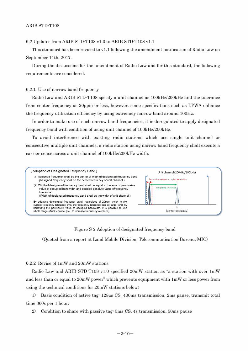
ARIB STD-T108
-3-10-
6.2 Updates from ARIB STD-T108 v1.0 to ARIB STD-T108 v1.1
This standard has been revised to v1.1 following the amendment notification of Radio Law on
September 11th, 2017.
During the discussions for the amendment of Radio Law and for this standard, the following
requirements are considered.
6.2.1 Use of narrow band frequency
Radio Law and ARIB STD-T108 specify a unit channel as 100kHz/200kHz and the tolerance
from center frequency as 20ppm or less, however, some specifications such as LPWA enhance
the frequency utilization efficiency by using extremely narrow band around 100Hz.
In order to make use of such narrow band frequencies, it is deregulated to apply designated
frequency band with condition of using unit channel of 100kHz/200kHz.
To avoid interference with existing radio stations which use single unit channel or
consecutive multiple unit channels, a radio station using narrow band frequency shall execute a
carrier sense across a unit channel of 100kHz/200kHz width.
Figure S-2 Adoption of designated frequency band
(Quoted from a report at Land Mobile Division, Telecommunication Bureau, MIC)
6.2.2 Revise of 1mW and 20mW stations
Radio Law and ARIB STD-T108 v1.0 specified 20mW station as “a station with over 1mW
and less than or equal to 20mW power” which prevents equipment with 1mW or less power from
using the technical conditions for 20mW stations below;
1) Basic condition of active tag: 128µs-CS, 400ms-transmission, 2ms-pause, transmit total
time 360s per 1 hour.
2) Condition to share with passive tag: 5ms-CS, 4s-transmission, 50ms-pause

ARIB STD-T108
-3-11-
In order for a station with 1mW or less power to use the above-mentioned technical
conditions, the lower limitation for 20mW station is removed. As this may lead to
duplicated provisions regarding the former 1mW station, ARIB STD-T108 clarifies them by
using following categories;
“1mW or less (with no carrier sense)” : the former “1mW or less”
“20mW or less (with carrier sense)” : the former “over 1mW and less than or equal to
20mW” and old “1mW or less” with conditions 1) and 2) above.
However, as for a radio channel mask for equipment with 1mW or less power, in case that a
carrier sense is required, the radio channel mask for equipment with 20mW or less power is
applied.
6.2.3 Adoption of EIRP method
Radio Law and ARIB STD-T108 specify antenna power of radio equipment and antenna gain
respectively. However, it has been allowed to compensate for the loss by increasing antenna
gain if the antenna power is lower than the limit.
In this revision, it is mitigated that the loss of poor antenna gain can be compensated for by
increasing the antenna power as Figure S-3 depicts.
Figure S-3 Adoption of EIRP method
(Quoted from a report at Land Mobile Division, Telecommunication Bureau, MIC)
ARIB STD-T108
-3-12-
[EIRP conditions]
20mW or less: Equivalent isotropic radiated power (antenna power + antenna gain) ≤
16dBm
1mW or less: Equivalent isotropic radiated power (antenna power + antenna gain) ≤
3dBm
where an equivalent isotropic radiated power is a sum of transmit antenna gain and
antenna power and it includes the tolerance of antenna power.
[Condition to use / Notes]
Antenna shall be integrated with radio equipment. Therefore, EIRP provision is not
applicable to equipment which uses external/removal antennas.
Maximum antenna power is 250mW.
In a test like Technical Regulations Conformity Certification, antenna power and
antenna gain are measured separately the same as before. Especially, when antenna power is
operated more than 20mW/1mW as per mitigation in this revision, it is essential to measure
characteristics of antenna gain.
[Adjustment of carrier sense level]
Because reception performance tends to be degraded when low gain antenna is used, the
carrier sense level shall be lowered according to the amount of the increase of antenna power in
order to ensure the carrier sense capability within communication area, as depicted in Figure
S-4.

ARIB STD-T108
-3-13-
Figure S-4 Adjustment of carrier sense level
6.3 Updates from ARIB STD-T108 v1.1 to ARIB STD-T108 v1.2
This standard was revised to version 1.2 for the purpose of smooth operation of LPWA.
6.3.1 Channel extension of land mobile station (250 mW) passive sharing condition
In STD-T108 v1.1, a passive sharing condition (a condition to perform transmission of 4 s or
less after 5 ms carrier sense and pause for 50 ms or more after 5 ms carrier sense) is performed
on a frequency channel with a center frequency of 920.6 MHz or more and 922.2 MHz or less in
order to implement uplink and downlink with the same channel, it was necessary to use a
frequency channel with a center frequency of 920.6 MHz or more and 922.2 MHz or less.
However, since this frequency channel is a frequency channel mainly used by the passive tag
system, there is a possibility of interference.
To avoid that, the frequency channel that can use the passive sharing condition in the land
mobile station is extended to the same center frequency 920.6 MHz or more and 923.4 MHz or
less as the ministerial ordinance.
However, for frequency channels with a center frequency of 922.4 MHz or more and 923.4
MHz or less, considering the influence on existing radio stations, the total transmission time per
hour shall be 360 seconds or less. Also, it is desirable not to perform continuous transmission.
6.3.2 Conditions for frequency channel change
In order to improve the utilization efficiency of a system which operates while transiting a

ARIB STD-T108
-3-14-
plurality of frequency channels, the provision of "pause of 10 times transmission time", which
was essential at the time of using a unit channel, is deleted
In addition, when moving over frequency channels, it is desirable to shift to a channel with a
frequency as far as possible, in consideration of the influence on adjacent channels.
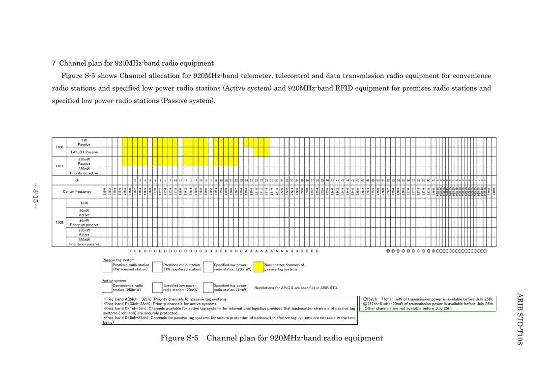
ARIB
STD-T108
-3-15
-
7 Channel plan for 920MHz-band radio equipment
Figure S-5 shows Channel allocation for 920MHz-band telemeter, telecontrol and data transmission radio equipment for convenience
radio stations and specified low power radio stations (Active system) and 920MHz-band RFID equipment for premises radio stations and
specified low power radio stations (Passive system).
Figure S-5 Channel plan for 920MHz-band radio equipment
1WPassive
1W・LBT Passive
250mWPassive
250mWPriority on active
1 2 3 4 5 6 7 8 9 10 11 12 13 14 15 16 17 18 19 20 21 22 23 24 25 26 27 28 29 30 31 32 33 34 35 36 37 38 39 40 41 42 43 44 45 46 47 48 49 50 51 52 53 54 55 56 57 58 59 60 61 62 63 64 65 66 67 68 69 70 71 72 73 74 75 76 77
915.0
915.2
915.4
915.6
915.8
916.0
916.2
916.4
916.6
916.8
917.0
917.2
917.4
917.6
917.8
918.0
918.2
918.4
918.6
918.8
919.0
919.2
919.4
919.6
919.8
920.0
920.2
920.4
920.6
920.8
921.0
921.2
921.4
921.6
921.8
922.0
922.2
922.4
922.6
922.8
923.0
923.2
923.4
923.6
923.8
924.0
924.2
924.4
924.6
924.8
925.0
925.2
925.4
925.6
925.8
926.0
926.2
926.4
926.6
926.8
927.0
927.2
927.4
927.6
927.8
928.0
928.1
5928.2
5928.3
5928.4
5928.5
5928.6
5928.7
5928.8
5928.9
5929.0
5929.1
5929.2
5929.3
5929.4
5929.5
5929.6
5
929.8
930.0
1mW
20mWActive
20mWPriory on passive
250mWActive
250mWPriority on passive
C C C C C D D D D D D D D D D D D D D D D D D A A A A A A A A A B B B B B B ◎ ◎ ◎ ◎ ◎ ◎ ◎ ◎ ◎ ◎○○○○○○○○○○○○○○○○
Passive tag system
Active system
Restrictions for A,B,C,D are specified in ARIB STD.Specified low powerradio station (1mW)
Premises radio station(1W licensed station)
Convenience radiostation (250mW)
Specified low powerradio station (20mW)
Backscatter channels ofpassive tag systems
Specified low powerradio station (250mW)
Premises radio station(1W registered station)
T108
T106
T107
ch
Center frequency
・Freq. band A(24ch-32ch):Priority channels for passive tag systems.・Freq. band B(33ch-38ch):Priority channels for active systems.・Freq. band C(1ch-5ch):Channels available for active tag systems for international logistics provided that backscatter channels of passive tagsystems (1ch-4ch) are securely protected.・Freq. band D(6ch-23ch):Channels for passive tag systems for secure protection of backscatter. (Active tag systems are not used in the timebeing)
・〇(52ch-77ch):1mW of transmission power is available before July 25th.・◎(57ch-61ch):20mW of transmission power is available before July 25th. Other channels are not available before July 25th.


To: Secretariat of Standard Assembly Meeting of the Association of Radio Industries and Businesses FAX: +81-3-3592-1103 E-mail:[email protected] Nittochi Bldg. 11th Floor, 1-4-1 Kasumigaseki, Chiyoda-ku, Tokyo 100-0013, Japan
Communication Note of ARIB Standard-related Proposals, etc.
ARIB Standard Name (No.)
920MHz-BAND TELEMETER, TELECONTROL AND DATA TRANSMISSION RADIO EQUIPMENT FOR SPECIFIED LOW (ARIB STD-T108)
Sections to be completed by sender Name: Date / / /
TEL: FAX: E-mail:
Company name Department name
Page / Section
(Please describe your proposal or present your questions or comments in concrete terms.)
(Response)
Sections to be completed by secretariat
Date of receipt / / /
Ref. No. -
Classification: Remarks
Please send your ARIB Standard-related question in this format. If you complete this form in English, please provide Japanese translation alongside the English.

920MHz-BAND
TELEMETER, TELECONTROL AND DATA TRANSMISSION RADIO EQUIPMENT
ARIB STD-T108 Version 1.2
Version 1.0 February 14th 2012 Version 1.2 January 22th 2018
Published by Association of Radio Industries and Businesses
11F, Nittochi Building,
1-4-1 Kasumigaseki, Chiyoda-ku, Tokyo 100-0013, Japan TEL 03-5510-8590 FAX 03-3592-1103
Printed in Japan
All rights reserved