IntelliGen® RULV Dispense System - entegris.com · 2 FEATURES & BENEFITS — Two-stage dispense...
13
1 ADVANCED MATERIALS HANDLING Advanced two-stage system with built-in interface module enables superior filtration and dispense IntelliGen ® RULV Dispense System Built-in, robust RDS-01 V2 control module enables liquid dispense volume accuracy and repeatability monitoring Built on the proven performance of the advanced two-stage dispense technology combined with Entegris’ innovative Connectology ® filter design, the IntelliGen ® RULV dispense system integrates high-purity filtration with repeatable dis- pense of low-viscosity fluids (1–100 cP or at higher viscosities when dispense pressure does not exceed 29 psi). This pump system is designed exclusively for use with TEL Clean Track TM ACT TM 12/ACT 8 track systems. Developed as a sanitized dispense system for lithography process, the IntelliGen RULV dispense system can dispense a more uniform topography of photochemical coating on the wafer. It also helps to shorten start-up times and provides intelligent dispense diagnostics. The compatible Impact ® 8G or Impact 2 V2 (OF style) filter easily slides into the IntelliGen RULV system's compartment. Fluids pass through the Impact filter at the optimum flow rate for the specific retention rating, improving throughput and increasing uptimes. The integrated, dual pressure sensors provide real-time alerts and enhance filter priming by providing several confirmation features including dispense confirmation, cycle time confirma- tion, and delta P confirmation. These confirmations help to prevent costly wafer defects caused by coating problems and random DC error occurrences triggered by backlash issues at lower ready pressure levels. The state-of-the art air detection feature pinpoints when air enters the outlet tubing from a leak or from minute air bubble formations that gradually accumulate over time. The RDS-01 controller's superior performance, and interactive diagnostics make the IntelliGen RULV dispense system the right choice for low viscosity photoresist to ensure dispense repeatability, longer filter life, and great return on investment.
-
Upload
vuongkhanh -
Category
Documents
-
view
215 -
download
0
Transcript of IntelliGen® RULV Dispense System - entegris.com · 2 FEATURES & BENEFITS — Two-stage dispense...

1
ADVANCED MATERIALS HANDLING
Advanced two-stage system with built-in interface module enables superior filtration and dispense
IntelliGen® RULV Dispense SystemBuilt-in, robust RDS-01 V2 control module enables liquid dispense volume accuracy and repeatability monitoring
Built on the proven performance of the advanced two-stage
dispense technology combined with Entegris’ innovative
Connectology® filter design, the IntelliGen® RULV dispense
system integrates high-purity filtration with repeatable dis-
pense of low-viscosity fluids (1–100 cP or at higher viscosities
when dispense pressure does not exceed 29 psi). This pump
system is designed exclusively for use with TEL Clean TrackTM
ACTTM 12/ACT 8 track systems.
Developed as a sanitized dispense system for lithography
process, the IntelliGen RULV dispense system can dispense
a more uniform topography of photochemical coating on
the wafer. It also helps to shorten start-up times and provides
intelligent dispense diagnostics. The compatible Impact® 8G
or Impact 2 V2 (OF style) filter easily slides into the IntelliGen
RULV system's compartment. Fluids pass through the Impact
filter at the optimum flow rate for the specific retention rating,
improving throughput and increasing uptimes.
The integrated, dual pressure sensors provide real-time alerts
and enhance filter priming by providing several confirmation
features including dispense confirmation, cycle time confirma-
tion, and delta P confirmation. These confirmations help to
prevent costly wafer defects caused by coating problems and
random DC error occurrences triggered by backlash issues at
lower ready pressure levels.
The state-of-the art air detection feature pinpoints when air
enters the outlet tubing from a leak or from minute air bubble
formations that gradually accumulate over time. The RDS-01
controller's superior performance, and interactive diagnostics
make the IntelliGen RULV dispense system the right choice for
low viscosity photoresist to ensure dispense repeatability, longer
filter life, and great return on investment.

2
FEATURES & BENEFITS—
Two-stage dispense technology with Connectology filter design
Integrates high-purity filtration with excellent dispense repeatability of low-viscosity fluids (1–100 cP or higher viscosities when dispense pressure does not exceed 29 psi)
Independently optimized dispense and filtration sequences
Advanced closed-loop software control with several additional fault detection features
Integrates with Impact 8G or Impact V2 (OF style) filter
• Slides into ULV compartment for bubble, gel, and particle removal
• The RULV pump is applicable to only Tokyo Electron Act 12/Act 8 tools
Built-in technology enhancements — PCB and dual sensors added
Enhanced filtration control
Expandable capabilities without memory limitations
Extension of confirmation tools
• Delta P
Better startup and filter priming technology
Real-time clock technology with traceability
More reliable dispense settings Ball screw incorporated into dispense motor
Lower ready pressure setting available
Improved chemical turnover technology
Chamber design facilitates chemical turnover
Adjustable fill chamber reduces hold-up volume
Valve design more effectively clears contaminants
Initial cleanliness technologies Introduction of unique post production cleaning procedure
Optional enhancements Flowmeter RSQ confirmation
• Finer one-shot volume detection
• Microbubble detection

3
SPECIFICATIONS—
Dispense performance Volume 0.01 – 10.0 mL in 0.001 mL increments
Rate 0.01 – 3.0 mL/sec in 0.001 mL/sec increments
Repeatability ≤ 0.02 mL 3 sigma
Viscosity range* 1 – 100 cP
Maximum dispense design pressure**
0.21 MPa (30 psi)
Recharge performance Fill rate, filtration rate, vent rate, purge rate
0.1 – 3.0 mL/sec in 0.001 mL/sec increments
Vent frequency Auto-venting or 1 –10,000 dispense cycles
Mechanical Wetted surfaces Modified PTFE, PTFE, Kalrez®
Connection type Inlet: Insert style, Super Type Pillar®
Outlet and vent: Flaretek®
Filter Impact 8G or Impact 2 V2 (OF style)
Inlet, outlet and vent tubing
OD: 6.35 mm (0.25") or 6.0 mm (0.24")
ID: 3.97 mm (0.156") or 4.0 mm (0.16")
Inlet gas type Regulated N2 or CAD
Operating conditions Minimum operating pneumatic pressure: 0.26 MPa (38 psi)
Maximum operating pneumatic pressure: 0.28 MPa (40 psi)
Pneumatic leak pressure: 0.30 MPa (43 psi)
Vacuum - 68 kPa (20 in-Hg min)
Dimensions Height 303.5 mm (11.95")
Width 118.0 mm (4.65")
Depth 156.8 mm (6.17")
Weight Approximately 4.5 kg (10 lbs)
Electrical Current rating 1.25A maximum
Input voltage (system) 24 VDC ±10%
Serial communication Specifications are dependent on interface module use
Parallel communication Triggers and acknowledgments
Certifications See provided documentation
Environment Indoor use only
Altitude below 2000 m (2187.22 yd)
Ambient temperature 5° – 40°C (41° – 104°F)
Maximum relative humidity 80% for temperatures up to 31°C (88°F) decreasing linearly to 50% relative humidity at 40°C (104°F)
Main supply fluctuations from 22 – 26 VDC
Transient overvoltages of overvoltage category II
Pollution degree 2
* Depends on tool configuration. Contact applications support for detailed window of operation. ** Maximum pressure is a limit on the Window of Operation. Actual volumes and rates may be restricted
to comply with the pressure limits for a given viscosity, tubing diameter, tubing length, and tubing height.
4
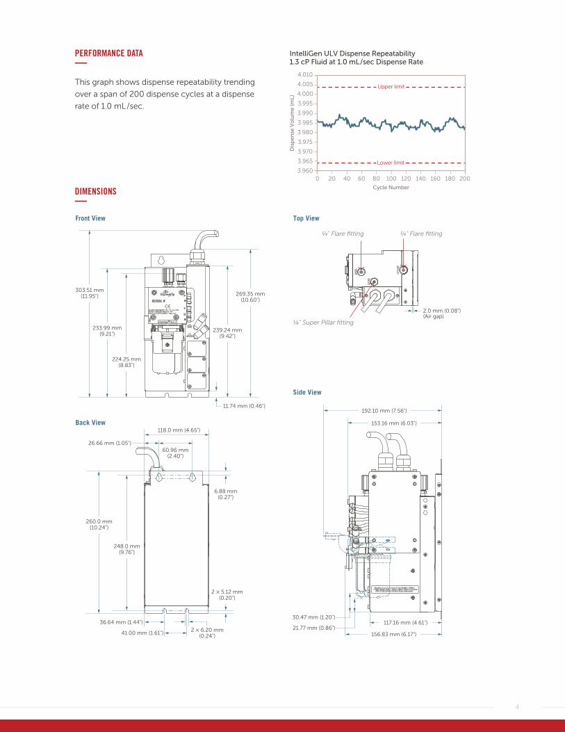
PERFORMANCE DATA—This graph shows dispense repeatability trending
over a span of 200 dispense cycles at a dispense
rate of 1.0 mL /sec.
DIMENSIONS—
303.51 mm(11.95")
260.0 mm(10.24")
248.0 mm(9.76")
233.99 mm(9.21")
224.25 mm(8.83")
239.24 mm(9.42")
11.74 mm (0.46")
6.88 mm (0.27")
60.96 mm (2.40")
118.0 mm (4.65")
192.10 mm (7.56")
2.0 mm (0.08")(Air gap)
153.16 mm (6.03")
156.83 mm (6.17")
117.16 mm (4.61")21.77 mm (0.86")
30.47 mm (1.20")
26.66 mm (1.05")
2 × 6.20 mm(0.24")
2 × 5.12 mm(0.20")
36.64 mm (1.44")
41.00 mm (1.61")
269.35 mm(10.60")
Front View
Back View
Side View
Top View
1⁄4" Super Pillar fitting
1⁄4" Flare fitting 1⁄4" Flare fitting
4.010
4.005
4.000
3.995
3.990
3.985
3.980
3.975
3.970
3.965
3.960
IntelliGen ULV Dispense Repeatability1.3 cP Fluid at 1.0 mL/sec Dispense Rate
Dis
pen
se V
olu
me
(mL)
Cycle Number
Upper limit
Lower limit
40 140100 1800 12080 160 20020 60

5
SYSTEM SCHEMATIC – FLUID PIPING, UTILITY, AND ELECTRICITY—
Computer
Solenoid valve
DrainVent Outlet
Nozzle
Wafer
FlowmeterOutletvalve
Inlet
L/E
Bottle
N2 pressureN2 pressure and vacuum
I/O signal Pump cable
RS232-422converter
Trackinterface
24 V power
No independent interface module needed
FluidUtilityElectricity
IntelliGen RULV dispense system
(RDS-01 V2 module built in)

6
Quantity1 = 1/pack
Pleating style0 = StandardM = M-pleat
O-ringK = Kalrez
Configuration0 = StandardRetention rating
K = 3 nmF = 5 nmT = 10 nmX = 20 nmMembrane
S = AsymmetricC = UPED = DuoN = NylonM = PCM
Impact 8G and 8G UC Series Filters: part number
A2 C 0 K 1 UC
Cleaning*UC = Ultraclean
* Cleaning only applies to Impact 8G UC series filters.
Quantity1 = 1/pack
Pleating style0 = StandardM = M-pleat**
O-ringK = Kalrez
Open0 = Standard
Retention ratingK = 3 nmF = 5 nmT = 10 nmX = 20 nm
Y = 30 nmZ = 0.05 µmV = 0.1 µmG = 0.2 µmMembrane
A = Thin UPE (symmetric)S = AsymmetricD = DuoM = PCMN = Nylon
Impact 2 V2 Filters: part number
A2 2 0 K 1
** The M-pleat style only applies to Impact filters with a UPE membrane of up to 30 nm.
ORDERING INFORMATION − DISPENSE SYSTEM—The following table lists the IntelliGen RULV dispense system and accessories part numbers.
Part number Description
IGLNPVBPF1F1 Dispense system: Inlet fitting Super Pillar type/Outlet and vent fitting Flaretek type: IntelliGen RULV for RDS01 retrofit with EX clean
IGLNPSP01 Cable parts: RS232C host cable for RULV
IGLNPSP02 Cable parts: RS232C 5CM host cable for RULV
IGLNPSP03 Cable parts: RS422 host cable PLS GND for RULV
IGLNPSP04 Cable parts: RS422 DG chain cable PLS GND for RULV
IGLNPSP05 Flowmeter cable parts: Flowmeter RS485 2M cable for RULV
IGLNPSP06 Flowmeter cable parts: Flowmeter RS485 5M cable for RULV
The following ordering information serves as a guide. Please contact your local representative to confirm part numbers.

7
RDS-01 V2 CONTROLLER WITH OPTIONAL FLOWMETER—In lithography processes, it is advantageous to
observe photochemical flow quality to ensure flow
consistency and a highly repeatable process. Inte-
grating a sensitive flow monitoring system will
enable better quality control and defect reduction.
Building on the repeatability of Entegris’ IntelliGen
dispense system product line, Entegris has developed
the robust RDS-01 V2 controller that provides the
ideal interface for connecting the IntelliGen two-
stage dispense system to a wide range of semicon-
ductor coating systems.
The RDS-01 V2 controller is built as one compartment
of the IntelliGen RULV dispense system. This makes it
easy for users to upgrade their dispense unit with the
robust, RDS-01 V2 controller. For an added advantage
monitoring flow characteristics, a flowmeter may be
integrated into the RDS-01 V2 controller.
The optional flowmeter allows reliable observation of
the liquid flow profile and flow volume in the outlet
tube. It is a very sensitive system that can detect a
slight change in the flow characteristic. Its MMI soft-
ware records the flow profile and flow volume and
detects abnormal events that cause a change in the
flow characteristic. Early detection of abnormal events
helps reduce costly defects and prevent yield loss.
IntelliGen RULV dispense system – RDS01 V2 controller (in yellow frame) built-in design and flowmeter (bottom image).
ORDERING INFORMATION – FLOWMETER AND ACCESSORIES—
Part number Description
IGLFMHM01 IG flowmeter type 1 OD 6.35 mm
IGRDS01SP01 IG module ver.2 RDS01 RS422 main cable
IGRDS01SP02 IG module ver.2 RDS01 RS422 chain cable

8
PERFORMANCE DATA – RDS-01 V2 CONTROLLER—Electrical performance data
Number Point Content
1 Power circuit 1-1 Reinforcement of protection circuit (overvoltage, overcurrent, and reverse input)
2 DIP switch 2-1 Two DIP switches were integrated into one for the pump address
2-2 Separated a 2-POS type DIP switch for RS422 termination
2-3 Added a 6-POS type DIP switch for the RS422/RS485 fail-safe in order to stabilize a signal on a static state level (optional use)
3 LED onboard 3-1 Added LEDs in 232 /422 TX and 232 /422 RX serial communication lines
3-2 Added LED for the DC-Error
3-3 Added LED for the FLOW-Error
POWER CIRCUIT LAYOUT—
RDS-01 V2 controller.
1
2-3
2-2
3-3
3-2
2-1
3-1

9
PERFORMANCE DATA – FLOWMETER—Performance of the optional flowmeter, SLQ-QT500 (all data for medium IPA, 23°C, unless otherwise noted)
Parameter SLQ-QT500 (IPA) SLQ-QT500 (H2O)
Full scale flow rate 2000 (120) µL/s (mL/min) 2000 (120) µL/s (mL/min)
Flowmeter output limit1 2500 (150) µL/s (mL/min) 2500 (150) µL/s (mL/min)
Accuracy below full scale (whichever error is larger)2
5% of measured value 5% of measured value3
0.125% of full scale 0.125% of full scale
Repeatability below full scale (whichever error is larger)
0.5% of measured value 0.5% of measured value
0.0125% of full scale 0.0125% of full scale
Temperature coefficient (additional error per °C, whichever is larger)
0.15% of measured value/°C 0.15% of measured value/°C
0.00375% of full scale/°C 0.00375% of full scale/°C
Flow detection response time <50 ms <50 ms
Response time on power-up 25 ms 25 ms
Operating temperature 5° to 50°C 5° to 50°C
Ambient storage temperature4 -10° to 60°C -10° to 60°C
Operating pressure5 12 bar (175 psi) 12 bar (175 psi)
Proof pressure5 50 bar (725 psi) 50 bar (725 psi)
1. Flow rate at which the flowmeter output saturates. 2. Accuracy with straight inlet tube. 3. Accuracy below ±1000 μL/s (see the chart in section 2 for the accuracy between 1000 μL/s and 2500 μL/s). 4. Uncondensed, flow path empty.5. Pressure limited by PFA tubing.

10
ELECTRICAL SPECIFICATION – FLOWMETER—DC characteristics
Parameter Minimum Typical Maximum
Power supply DC, VDD 3.3 V 5.1 V 3.7 V
Operating current — 3.5 V —
ELECTRICAL CONNECTOR AND PINPOINTS – FLOWMETER—Electrical pinpoints
Pin Description
1 SDA (data)
2 GND
3 VDD
4 SCL
FLUIDIC CONNECTION – FLOWMETER—Fluidic specification and pressure rating
Parameter
Wetted materials Internal sensor tube material Quartz
Connection tube PFA
Fluidic connection PFA tube, 6.35 mm (1/4") OD, 4.35 mm ID
Pressure drop @ 120 mL/min IPA, 23°C
<2 mbar
Total internal volume <5 mL
1
4
3 2
Connecting pinpoint.

11
DIMENSIONS – FLOWMETER—
Parameter
Flowmeter body dimension 59 mm H × 35 mm W × 23.2 mm D (2.3" H × 1.4" W × 0.91" D)
Flowmeter overall length 360 mm ±10 mm (14" ±0.4")
Total mass ~45 g
Inner diameter sensor tube 4.5 mm (0.18")
Inner diameter PFA tube 4.35 mm (0.17")
MATERIALS 0F CONSTRUCTION – FLOWMETER—
Wetted materials
Component Material Flammability
¼" Connection tubing PFA UL-Q4-V-0
Capillary Quartz Not flammable
Housing PPS UL-Q4-V-0
Screw and electrical connector Stainless steel Not flammable
Cable Copper Not flammable
ETFE UL-Q4-V-0
23.1 mm(0.91")
12.0 mm(0.47")
7.5 mm (0.30")
150.0 mm ±5 mm(5.9" ±0.19")
150.0 mm ±5 mm(5.9" ±0.19")59.0 mm (2.3")
Chip
PFA
Quartz
35.0 mm(1.4")
25.0 mm (1.0")
45°
Ø6.35 mm(Ø0.25")
Ø4.35 mm(Ø0.17")
Ø4.5 mm (Ø0.18")
18.4 mm ±0.2 mm(0.72" ±0.01")
Ø19.0 mm(Ø0.75")
Ø25.0 mm(Ø1.0")
Ø35.0 mm(Ø1.4")
30.4 mm ±0.2 mm (1.20" ±0.01")
Sensirion label
Mounting holes, depth 12 mmDesign for EJOT Delta PT 22xNWN5451

12
APPLICATION DATA – FLOWMETER—Below is the RULV alarm page demonstrating two
types of alarms that alert when the flow characteristic
of the last cycle is different from that of the reference
(0.2 mL difference in flow volume). Flow profiles
shown in cycle 21367 and cycle 21372 are for the
reference and the last cycle, respectively.
It is hard to notice the difference between cycle 21367
(reference) and 21372 with your eyes. However, the
flow sensor is incredibly sensitive and can detect even
the slightest change in flow volume and alert the user.
This reliable flowmeter enables users to easily moni-
tor dispense flow consistency and achieve a highly
repeatable production process.
Confirm page on MMI screen. Two types of flow sensor alarms alert when flow volume is different from that of the reference.
Flo
w R
ate
(mL/
s)
2520155 100-5
Cycle 21367 (Reference)2
1.91.81.71.61.51.41.31.21.11
0.90.80.70.60.50.40.30.20.10
-0.1-0.2-0.3-0.4-0.5
Time (sec)
Cycle 21372
Flo
w R
ate
(mL/
s)
2520155 100-5
21.91.81.71.61.51.41.31.21.11
0.90.80.70.60.50.40.30.20.10
-0.1-0.2-0.3-0.4-0.5
Time (sec)
Flow profile of reference profile, dispense rate is 1.0 mL/s: dispense volume is 2.0 mL.
Flow profile of last cycle profile, dispense rate is 1.0 mL/s: dispense volume is 2.2 mL.
FOR MORE INFORMATION
Please call your Regional Customer Service Center today to learn what Entegris can do for you. Visit entegris.com and select the Contact Us link to find the customer service center nearest you.
TERMS AND CONDITIONS OF SALE
All purchases are subject to Entegris’ Terms and Conditions of Sale. To view and print this information, visit entegris.com and select the Terms & Conditions link in the footer.
www.entegris.com
129 Concord RoadBillerica, MA 01821 USA
Tel +1 952 556 4181Fax +1 952 556 8022Toll Free 800 394 4083
Corporate Headquarters Customer Service
Entegris®, the Entegris Rings Design®, and other product names are trademarks of Entegris, Inc. as listed on entegris.com/trademarks. All third-party product names, logos, and company names are trademarks or registered trademarks of their respective owners. Use of them does not imply any affiliation, sponsorship, or endorsement by the trademark owner.
©2018-2019 Entegris, Inc. | All rights reserved. | Printed in the USA | 3811-8606ENT-0719