INTEGRATED RADAR SENSORS FOR NON-CONTACT VITAL SIGNS … · 2012-02-10 · Medicine Battlefield...
28
Microwave Doppler Radar Sensor for Detection of Human Vital Signs and Mechanical Vibrations Prof. Jenshan Lin University of Florida Gainesville, FL http://www.lin.ece.ufl.edu/
Transcript of INTEGRATED RADAR SENSORS FOR NON-CONTACT VITAL SIGNS … · 2012-02-10 · Medicine Battlefield...

Microwave Doppler Radar Sensor for
Detection of Human Vital Signs and
Mechanical Vibrations
Prof. Jenshan Lin
University of Florida
Gainesville, FL
http://www.lin.ece.ufl.edu/

2
Video

A Simple Theory
Constant Velocity
Frequency Shift
Periodic Chest Wall Movement
Phase Shift
How does it work? Doppler Effect.
( )R t
( )T t
0d( )x t
0( )x t v t ( ) sin( )x t t
T t ft t ( ) cos 2 ( )
d dx tR t ft t
c
0 04 24 ( )
( ) cos 2 ( )3

• Use transmitted signal as reference to mix with received signal by
using a mixer or multiplier (similar to direct down-conversion), the
output baseband signal contains the vital sign signal in its phase.
A Simple Theory
T t ft t ( ) cos 2 ( )
d dx tR t ft t
c
0 04 24 ( )
( ) cos 2 ( )
T(t) x R(t) Baseband Signal B(t):
d x tB t
00
4 4 ( )( ) cos
0 d
t tc
02
( ) ( )Phase delay in receiver circuit
d
0
4 x t
4 ( )Antenna-to-target round-trip delay Phase modulation due to
chest-wall movement
4

Small Angle Approximation (Linear)
If x(t) << and [(4d0)/+0] = 90°, 270°, …
)(4)(4sin)(
txtxtB
This is what we want!
It is similar to measuring very small phase noise using FM discriminator
technique.
5
0
04)(4cos)(
dtxtB
90, 270 , … When
small negligible

• If the distance between radar sensor and target is small
enough, close-in phase noise of R(t) and T(t) are
correlated.
Range Correlation Effect
T t ft t ( ) cos 2 ( )
d dx tR t ft t
c
0 04 24 ( )
( ) cos 2 ( )
d x tB t
00
4 4 ( )( ) cos
Close-in phase noise correlated
~ 0 @ short-range
A. D. Droitcour, O. Boric-Lubecke, V. Lubecke, J. Lin, G. Kovacs, “Range Correlation and I/Q
performance benefits in single chip silicon Doppler radars for non-contact cardiopulmonary signs
sensing,” IEEE Trans. Microwave Theory Tech., Vol. 52, No. 3, pp. 838-848, March 2004 6
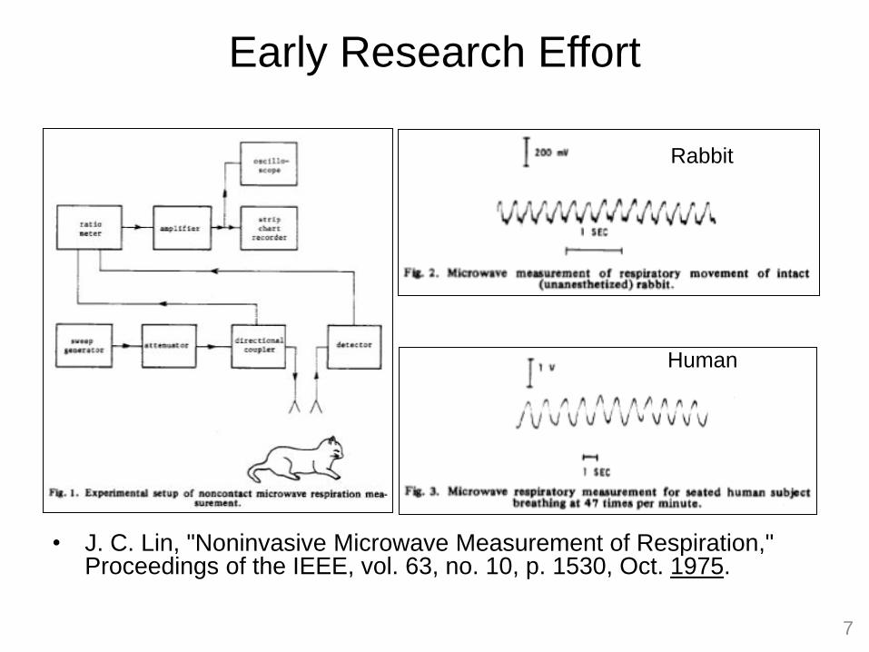
Early Research Effort
7
• J. C. Lin, "Noninvasive Microwave Measurement of Respiration," Proceedings of the IEEE, vol. 63, no. 10, p. 1530, Oct. 1975.
Rabbit
Human

Early Research Effort
8
• K.-M. Chen and H.-R. Chuang, “Measurement of Heart and Breathing Signals of Human Subjects Through Barriers with Microwave Life-Detection Systems,” IEEE EMBC 1988. – 10GHz: 1.5 ft of dry bricks – 2GHz: 3 ft of dry bricks
• H.-R. Chuang, Y.-F. Chen, and K.-M. Chen, “Automatic Clutter-Canceler for Microwave Life-Detection System,” IEEE Trans. Instrumentation and Measurement, Vol. 40, No. 4, August 1991.
10 GHz

RF Out to
Tx Antenna
Baseband +
Baseband -
RF In from
Rx Antenna
Buffer LO
Buffer
VCORF
Buffer
Mixer
RF Out to
Tx Antenna
Baseband +
Baseband -
RF In from
Rx Antenna
Buffer LO
Buffer
VCORF
Buffer
Mixer
• 0.25 µm BiCMOS
• 1.6 GHz transmission frequency
• 3.75mmx3.75mm
• Output power = 6.5dBm
First Non-Contact Vital Sign Sensor Chip
9
Balun
Balun
Balun
VCO
Mixer
RF out
(to Tx antenna)
RF in
(from Rx antenna)
Baseband out
Test Structures
VCO
LO Buffer
Buffer
RF Buffer
Mixer
Test Structures
VCO
LO Buffer
Buffer
RF Buffer
Mixer
A. D. Droitcour, O. Boric-Lubecke, V. Lubecke, J. Lin, “0.25m CMOS and BiCMOS Single Chip
Direct Conversion Doppler Radars for Remote Sensing of Vital Signs,” IEEE International Solid
State Circuits Conference Digest of Technical Papers, pp. 348-349, 2002.
Free-running VCO. No PLL.

Ka-band Bench-Top System
LabVIEW
Ka radar
Antenna
Subject
under test
Baseband
DAQ
10

User Interface Labview – data acquisition and signal processing
11

Typical Test Result
0 5 10 15 20 25-3
-2
-1
0
1
2
3
Time (Sec)D
ete
cte
d S
ign
al (V
)
0 5 10 15 20 2580
85
90
95
Time (Sec)
Be
ats
/Min
Detected heart beatReference heart beat2 % Higher than
Reference
2 % Lower thanReference
Time-Domain Signal
Calculated Heart Rate
12

Overnight Measurement
60
80
Be
ats
/Min
0 1 2 3 4 5 60
20
40
60
80
100
Time (Hour)
Be
ats
/Min
0 1 2 3 4 5 60
20
40
Bre
ath
s/M
in
Reference (Fingertip sensor)
Results of Ka - band radar
Duration: 6 hours
Accuracy: 92.96%
(Accuracy defined as within 2% of reference)
Carrier freq: 27.1 GHz
Measured from Back
C. Li, J. Lin, Y. Xiao, "Robust Overnight Monitoring of Human Vital Signs by a Non-contact
Respiration and Heartbeat Detector," Proceedings of the 28th IEEE Engineering in Medicine
and Biology Society Annual International Conference, pp. 2235-2238, September 2006 13

Nonlinear Doppler Phase Modulation
when = 90 and
xh(t), xr(t) <<
xr(t) <<
However, at mm-wave, the respiration movement is
no longer very small.
4 ( ) 4 ( )( ) cos( )
4 ( ) 4 ( )
h r
h r
x t x tB t
x t x t
14
Small angle approximation

Nonlinear Doppler Phase Modulation
4 ( ) 4 ( )( ) cos( )
4 4( ) ( )cos( )
h r
h rl k r h
k l
x t x tB t
m mJ J k t l t
Periodic body movements due to heartbeat and respiration
xh(t) = mh·sinωht, xr(t) = mr·sinωrt
f
k=1
l=0k=2
l=0k=3
l=0
k=0
l=1
0
k=0
l=0
k=-1
l=1
k=1
l=1
R1 R3 H1 R2 C1a C1b
C. Li, Y. Xiao, J. Lin, "Experiment and Spectral Analysis of a Low-Power Ka-Band Heartbeat Detector
Measuring from Four Sides of a Human Body," IEEE Transactions on Microwave Theory and
Techniques, IMS2006 Special Issue, Vol. 54, No. 12, pp. 4464-4471, December 2006. 15

Accurate Measurement of Periodic Motion
• Determining factors for harmonics due to phase
modulation
– Wavelength, or carrier frequency
– Residual phase
– Amplitude of periodic movement
1 2 3 4 1 2
3 4
4 4: : : | ( ) cos |:| ( )sin |:
4 4| ( )cos |:| ( )sin | .
m mH H H H J J
m mJ J
The amplitude of movement can be accurately determined
from the ratio of harmonics!
C. Li, J. Lin, "Non-Contact Measurement of Periodic Movements by a 22-40GHz Radar Sensor Using
Nonlinear Phase Modulation," IEEE MTT-S International Microwave Symposium Digest, pp. 579-582,
June 2007 16
H1 H2 H3 H4

Measurement Example
0 5 10 15-0.5
0
0.5
1
Time (Second)
Ba
se
ba
nd
Sig
na
l (V
)
0 1/3 2/3 1 4/3 5/3 20
0.5
1
Frequency (Hz)
No
rma
lize
d S
pe
ctr
um
1 1.5 2 2.5 30
1
2
3
4
5
Displacement (mm)
Ha
rmo
nic
Ra
tio
H3/H1 ratioH4/H2 ratio
Meaured H3/H1
Meaured H4/H2
• Movement period T = 3 sec amplitude = 2 mm
• fRF: 40 GHz,
• Transmission power: 50 µW
• Distance: 1.65m
(a) Baseband signal, spectrum (b) Displacement extraction,
self-verification 17
2.056 mm
2.045 mm

Random Body Movement Cancellation – Concept
• Physiological movements on both sides of the body
move in the same direction relative to their
respective detecting radar
• Random body drift move in the opposite direction
relative to their respective detecting radar
Heart
fI fQ
090
bIbQ
DAQ DAQDemodulation
090Body
18

Random Body Movement Cancellation – Theory
1 11
4 ( ) 4 ( ) 4 ( )( ) exp h r
f
x t x t y tS t j
2 22
4 ( ) 4 ( ) 4 ( )( ) exp h r
b
x t x t y tS t j
1 2 1 2
1 2
4 ( ) ( ) 4 ( ) ( )( ) ( ) ( ) exp h h r r
fb f b
x t x t x t x tS t S t S t j
Front:
Back:
Combine signals from both sides:
xh1, xh2, xr1, xr2: physiological movements
y(t): random body movement
1hx 2hx
1rx2rx
y
19
y(t) (random body movement) disappeared!

Random Body Movement Cancellation – Experiment
Body
ResHeart
fI fQ
090
bIbQ
DAQ DAQDemodulation
Res0
90
20 Isolation between two radars: antenna polarizations & slight frequency
offset between TX and RX

Random Body Movement Cancellation – Result
0 20 40 60 80 100 1200
0.5
1
Beats/Min
Co
mb
ine
d S
pe
ctr
um
Recovered heartbeat
(b)
0 20 40 60 80 100 1200
0.5
1
Beats/Min
Sp
ectr
um
FrontBack
(a)
0 2 4 6 8 10 12-1
-0.5
0
0.5
1
Time (Second)
Am
plit
ud
e
I ChannelQ Channel
(a)
0 2 4 6 8 10 12-1
-0.5
0
0.5
Time (Second)
Am
plit
ud
e
I ChannelQ Channel
(b)
Front
Back
C. Li, J. Lin, “Random Body Movement Cancellation in Doppler Radar Vital Sign
Detection,” IEEE Transactions on Microwave Theory and Techniques, vol. 56,
issue 12, pp. 3143-3152, December 2008. 21

Portable Module
Can be attached to laptop and powered through USB cable or
powered by battery.
22

Search and Rescue Robot
23

Software Configurable Radar Sensor Chip
inRF
outI +
outI -
outQ +
outQ -
Load Clk DataQ
LO +Q
LO
ILO +
ILO
LNAPre-Amp
MixerI
MixerQ
VGA
I
VGA
Q
Gm-boosted
biasBandgap Const-Gm
3-wire control
Gm Boosted Bias
Bandgap Constant Gm
LNA PreAmp
Mixer VGA
3 Wire Control Unit
RFin
Clock Data Load
Q
I
DAQ CPLD
5.8 GHz Radar Receiver
UMC 0.13 µm CMOS
1.2×1.2 mm2
C. Li, X. Yu, D. Li, L. Ran, J. Lin, "Software Configurable 5.8 GHz Radar Sensor Receiver
Chip in 0.13 μm CMOS for Non-contact Vital Sign Detection," IEEE RFIC Symposium
Digest of Papers, June 2009
24

Test Result
Power: 1.5 V battery
3-wire program: Xilinx XC9536 CPLD
Antenna: 2-by-2 patch array, 9 dB gain
DAQ: NI USB-6008, 12 bit, 0-5V input
0 5 10 15 20 25
-20
0
20
Time (Second)
I/Q
Sig
na
l [m
V]
0 20 40 60 80 100 1200
0.5
1
Beats/Min
CS
D S
pe
ctr
um
Respiration Heartbeat
0 5 10 15 20 25-40
-20
0
20
Time (Second)
I/Q
Sig
na
l [m
V]
0 20 40 60 80 100 1200
0.5
1
Beats/Min
CS
D S
pe
ctr
um
Respiration
Heartbeat
Detect from the back @ 0.5m away Detect from the front @ 1.5m away 25

Applications
Telemedicine
Rescue Security Sleep Apnea Baby Monitor
Veterinary
Medicine Battlefield
Triage
See-thru-wall
Radar
26

• Lie Detector – covert detection
• Emotion Detector – vital sensor in a phone
• Personal Radar Tricorder
• Sports – fitness center/gym
• RF Vibrometer
• Gaming/Entertainment – quiz contests, video games
– virtual reality
Applications
27

• Prototypes have been demonstrated at different
integration levels – bench-top, modules, and IC
chips.
• Basically, the technology can be used to detect
any motion of an object reflecting radio waves
• With proper signal processing, useful and
interesting information can be extracted for
various applications.
– Biometric Radar possible
Summary
28


![Automated Driving: Design and Verify Perception Systems...Velocity: [-9.37 0 0] Size: [0 1.8 0] Radar-based object detector Radar Detector SensorID = 2; Timestamp = 1461634696407521;](https://static.fdocuments.net/doc/165x107/5f775810e202332f2824eade/automated-driving-design-and-verify-perception-systems-velocity-937-0-0.jpg)