Doppler radar project Speed Detector
28
Doppler Shift Radar Speed Detector
-
Upload
eehirzallah -
Category
Education
-
view
815 -
download
5
description
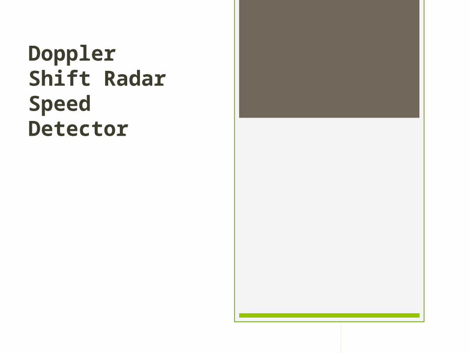
How to implement Cheap Speed Doppler Radar
Transcript of Doppler radar project Speed Detector
Doppler Shift Radar Speed Detector
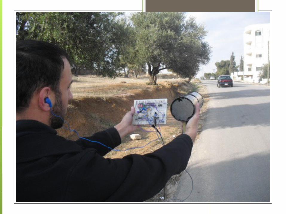
Initial Proposed Specifications
Speed range 0-99 mile/ hourTarget is a car or a humanCover operating distance range of
50-100 meterCheap and simple implementationSmall size, handheld and portable
Part1: Introduction and Radar RF
Part2: Displaying the Speed
Part3: Application Software
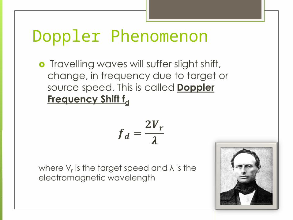
Doppler Phenomenon
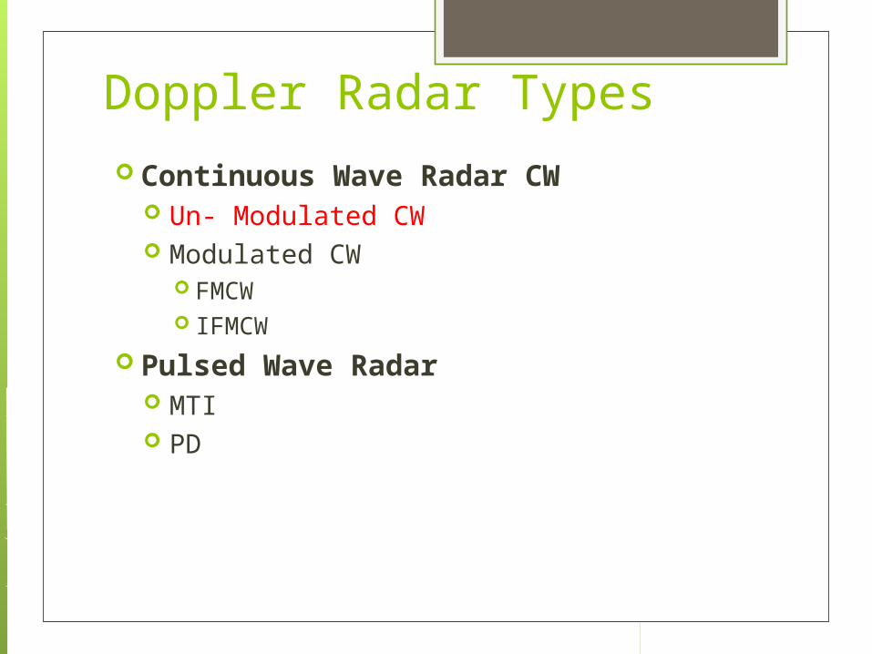
Doppler Radar Types Continuous Wave Radar CW
Un- Modulated CW Modulated CW
FMCW IFMCW
Pulsed Wave Radar MTI PD
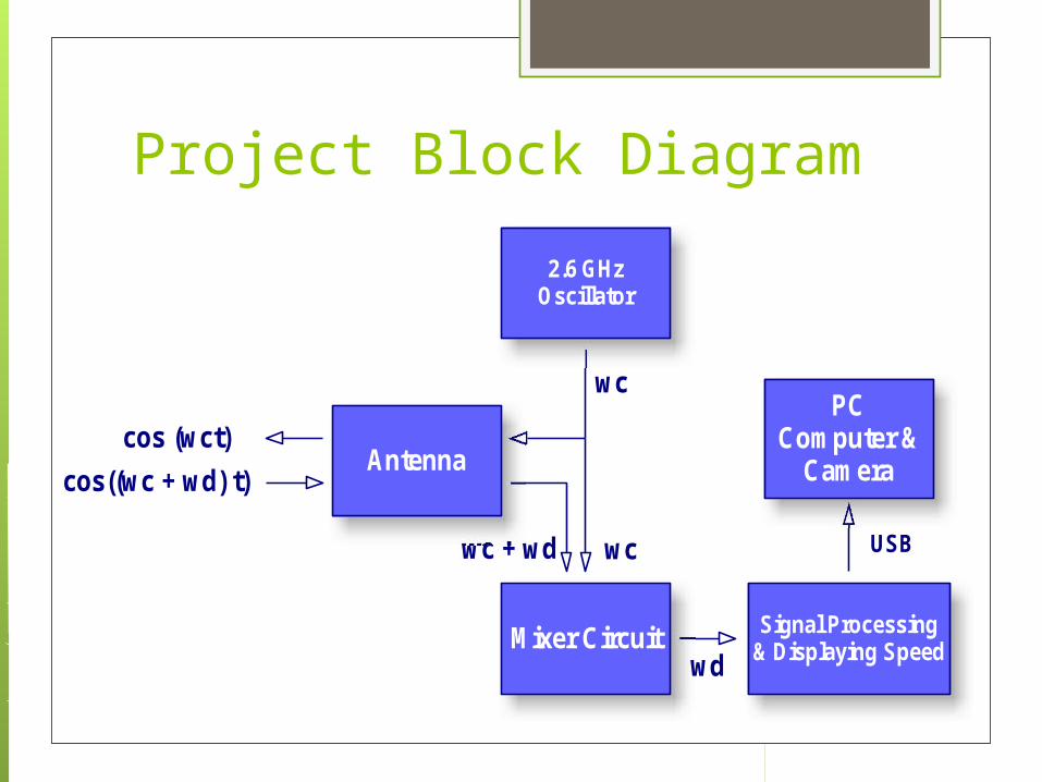
Project Block Diagram
Signal Processing& Displaying Speed
2.6 GHzOscillator
Mixer Circuit
PCComputer &
Cameracos (wct)
cos((wc + wd) t)
wc
wc + wd wc
wd
Antenna
USB
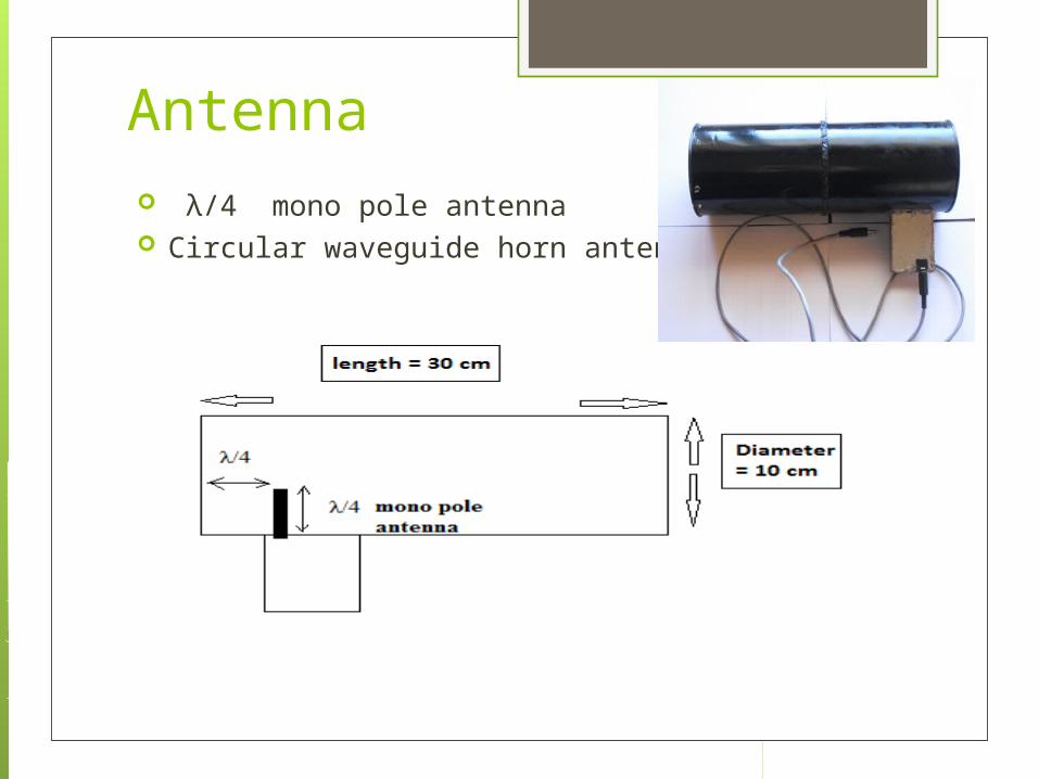
Antenna λ/4 mono pole antenna Circular waveguide horn antenna
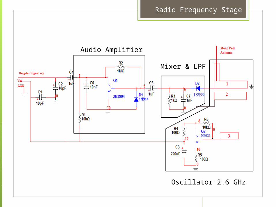
Radio Frequency Stage
Oscillator 2.6 GHz
Mixer & LPF
Audio Amplifier

RF Stage
Oscillator: 2.6 GHz Oscillator based on microwave transistor and PCB inductors and capacitors
Mixer & LPF: Schottky diode will mix both transmitted and Doppler shifted reflected signal using square law characteristics of diode junction
Audio Amplifier: common emitter amplifier will amplify Doppler signal

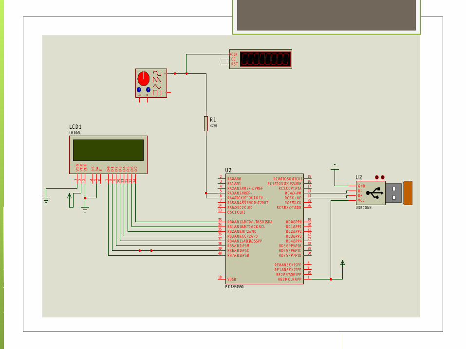
Part 2:Displaying The Speed & USB Connection
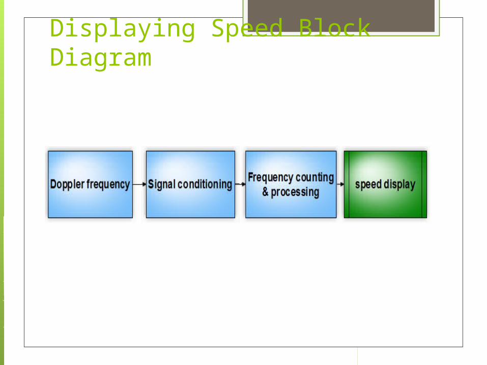
Displaying Speed Block Diagram

Conditioning Circuits
VCCD+D-GND
U2
USBCONN
AM FM
+
-
RST
CLKCE
R1470R
RA0/AN02
RA1/AN13
RA2/AN2/VREF-/CVREF4
RA3/AN3/VREF+5
RA4/T0CKI/C1OUT/RCV6
RA5/AN4/SS/LVDIN/C2OUT7
RA6/OSC2/CLKO14
OSC1/CLKI13
RB0/AN12/INT0/FLT0/SDI/SDA33
RB1/AN10/INT1/SCK/SCL34
RB2/AN8/INT2/VMO35
RB3/AN9/CCP2/VPO36
RB4/AN11/KBI0/CSSPP37
RB5/KBI1/PGM38
RB6/KBI2/PGC39
RB7/KBI3/PGD40
RC0/T1OSO/T1CKI 15
RC1/T1OSI/CCP2/UOE 16
RC2/CCP1/P1A 17
VUSB18
RC4/D-/VM 23
RC5/D+/VP 24
RC6/TX/CK 25
RC7/RX/DT/SDO 26
RD0/SPP0 19
RD1/SPP1 20
RD2/SPP2 21
RD3/SPP3 22
RD4/SPP4 27
RD5/SPP5/P1B 28
RD6/SPP6/P1C 29
RD7/SPP7/P1D 30
RE0/AN5/CK1SPP 8
RE1/AN6/CK2SPP 9
RE2/AN7/OESPP 10
RE3/MCLR/VPP 1
U2
PIC18F4550
D7
14D6
13D5
12D4
11D3
10D2
9D1
8D0
7
E6
RW
5RS
4
VSS
1
VDD
2
VEE
3
LCD1LM016L
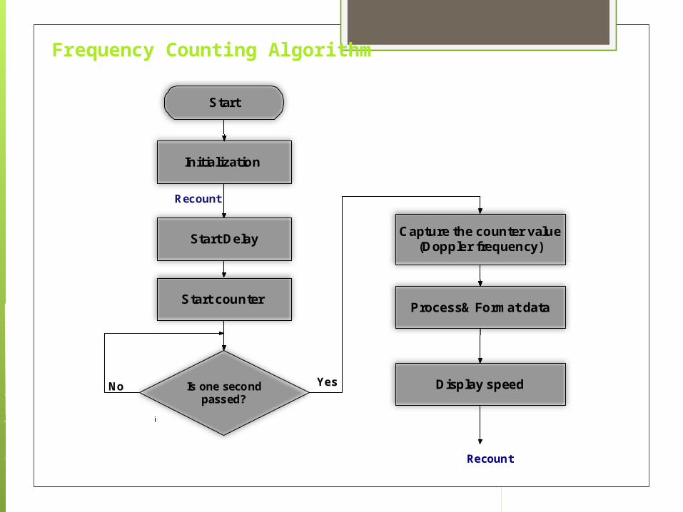
Frequency Counting Algorithm
Start
Capture the counter value(Doppler frequency)
Display speed
Process& Format data
i
Initialization
Is one secondpassed?
Yes
Start Delay
Start counter
Recount
No
Recount
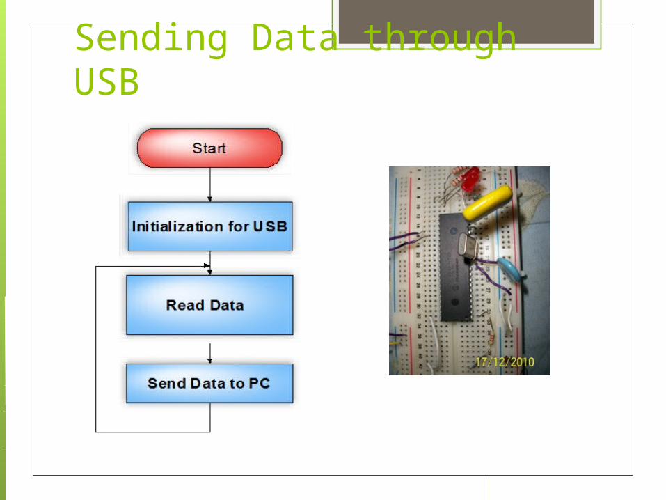
Sending Data through USB
Part3:Application Software
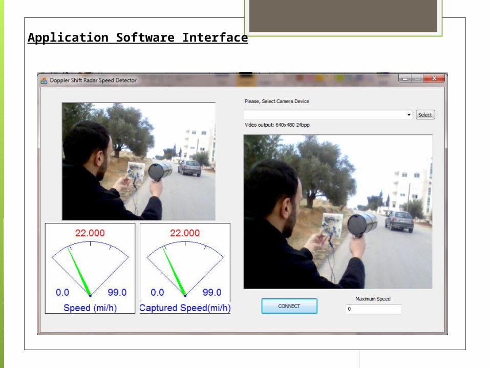
Application Software Interface
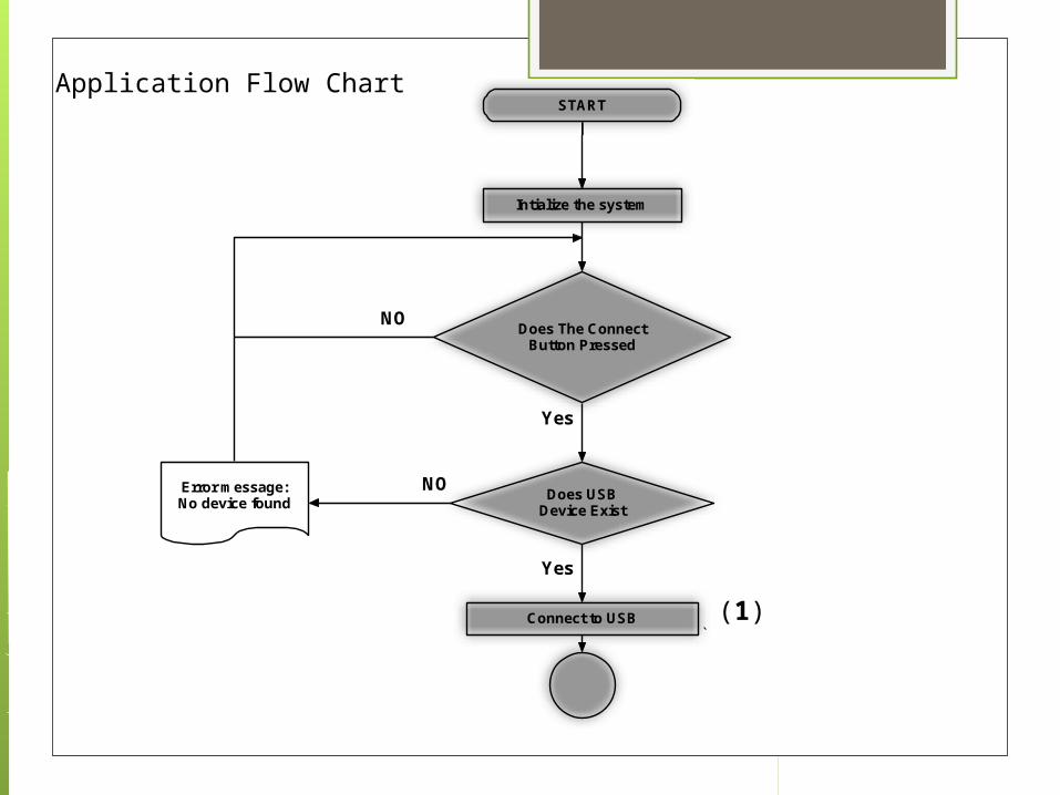
Intialize the system
START
Does The ConnectButton Pressed
Connect to USB
Yes
NO
Does USBDevice Exist
`
Error message:No device found
NO
Yes
Application Flow Chart
(1)

Run the Camera
Read Speed fromUSB and Display Itto the Left Meter
IF Speed>
Maxspeed
NO
Capture Image
Yes
Display InvalidSpeed to the Right
Meter
Flow chart continue…
(2)
(3)
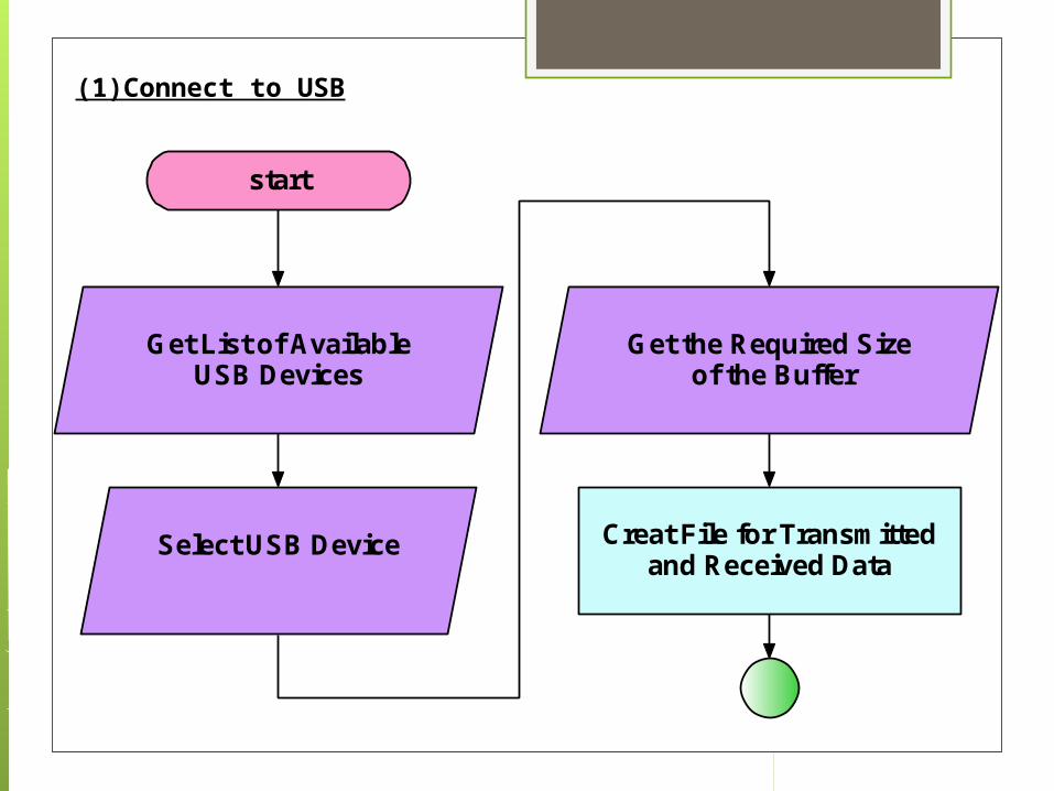
(1)Connect to USB
start
Get List of AvailableUSB Devices
Select USB Device
Get the Required Size of the Buffer
Creat File for Transmittedand Received Data
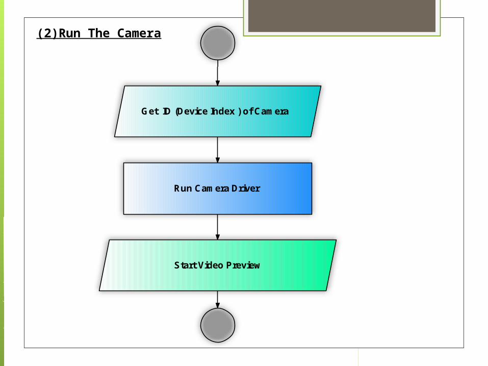
(2)Run The Camera
Get ID (Device Index ) of Camera
Start Video Preview
Run Camera Driver
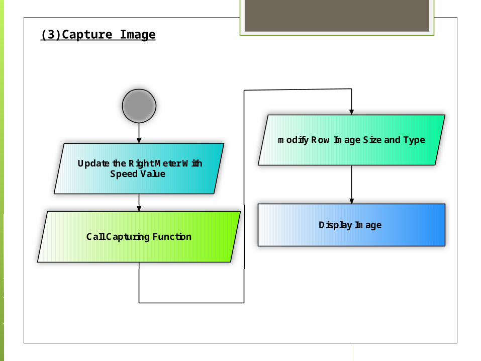
Update the Right Meter WithSpeed Value
modify Row Image Size and Type
Call Capturing FunctionDisplay Image
(3)Capture Image
Conclusion Microwave frequency affect circuit
analysis.
Air winds affect speed measurement, it is a clutter that affect radar performance.
Recommendations
Applying more analysis: Acceleration, Speed Profile and Jerk.
Image processing can be applied to detect special features in target image.
Images and Speeds can be sent remotely using internet, 3G or Wimax technology.

Thank you for Listening