
Integrated Circuit (IC) or Operational Amplifier (Op-amp) Connections
26
For Third year Biophysics Special Students. Prepared by: Abdo A. Elfiky. Assistant Lecturer, Biophysics Department, Faculty of Science, Cairo University.
-
Upload
cameron-mays -
Category
Documents
-
view
67 -
download
10
description
Integrated Circuit (IC) or Operational Amplifier (Op-amp) Connections. For Third year Biophysics Special Students. Prepared by: Abdo A. Elfiky. Assistant Lecturer, Biophysics Department, Faculty of Science, Cairo University. Introduction. Integrated circuit (IC), Microcircuit, Microchip, - PowerPoint PPT Presentation
Transcript of Integrated Circuit (IC) or Operational Amplifier (Op-amp) Connections
For Third year Biophysics Special Students.
Prepared by:Abdo A. Elfiky.
Assistant Lecturer, Biophysics Department, Faculty of Science,Cairo University.

IntroductionIntegrated circuit (IC),
Microcircuit, Microchip,
Silicon chip, or Chip) is a small electronic device made out of a semiconductorsemiconductor material. The first integrated circuit was developed in the 1950s.
There are two main advantages of ICs over discrete circuits: cost and performance.
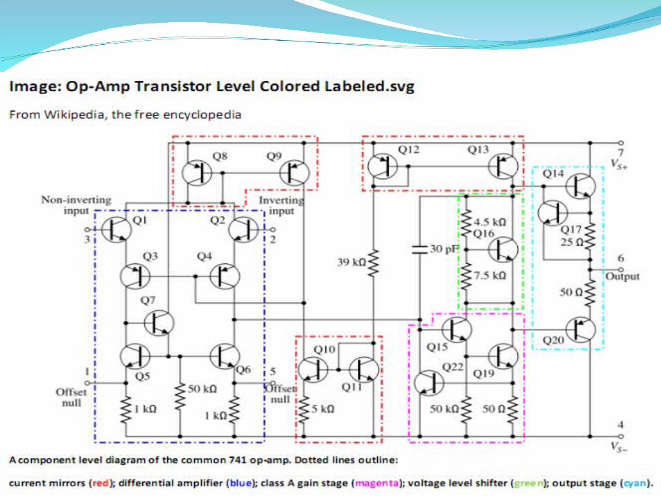
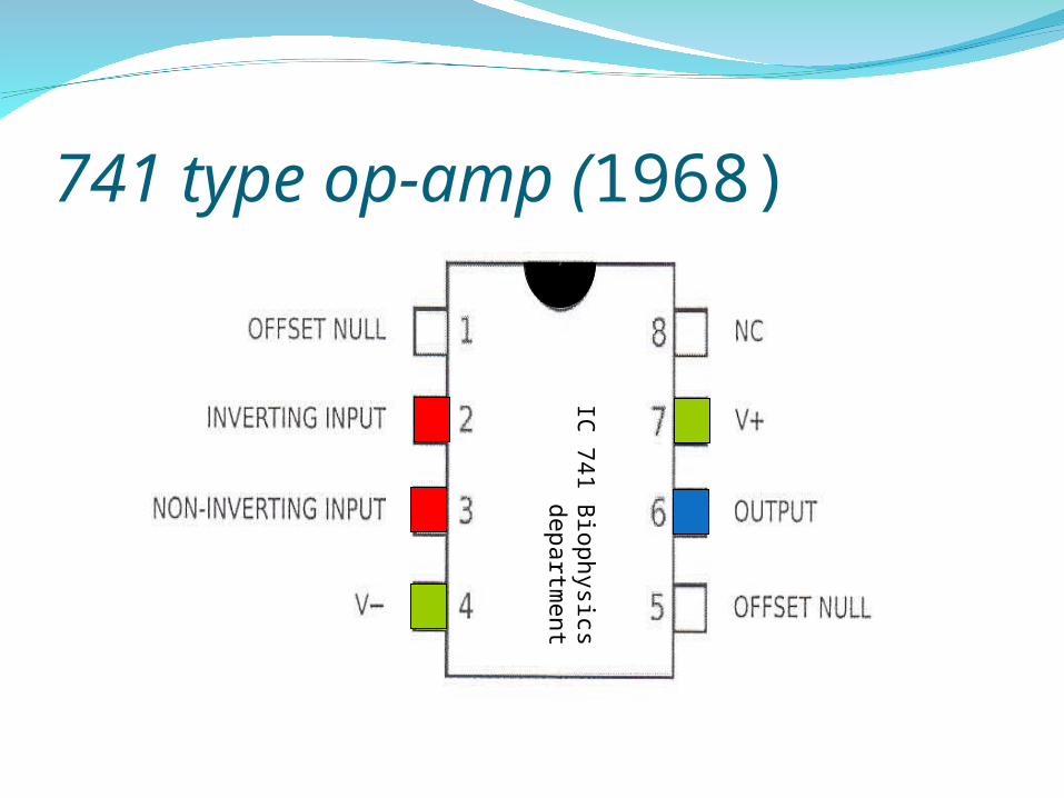
741 type op-amp (1968)
IC 7
41
Bio
physics d
epartm
ent

Op-Amp positioning on the board
IC 741 Biophysics department

Operational amplifierOp-amps were used to
perform mathematical operations such as additionaddition, subtractionsubtraction, integration integration,and differentiationdifferentiation, hence the term operational.
The op-amp has two input terminals, called the inverting input (-) and the non-inverting input (+), and one output terminal.


Open-Loop Voltage Gain Aol
1 volt
100,000 volts
1 volt

Closed-Loop Voltage Gain Acl
Op-amp can be connected using negative feedback to stabilize the gain and increase frequency response.
Negative feedback takes a portion of the output and applies it back out of phase with the input, creating an effective reduction in gain. This closed-loop gain is usually much less than the
open-loop gain and independent of it.

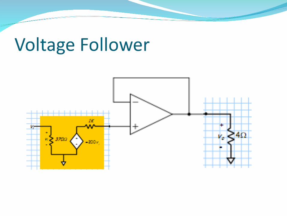
Voltage FollowerUsed as a buffer amplifier to eliminate
loading effects or to interface impedances (connecting a device with a high source impedance to a device with a low input impedance)
1 volt
100,000 volts
-99,999 V
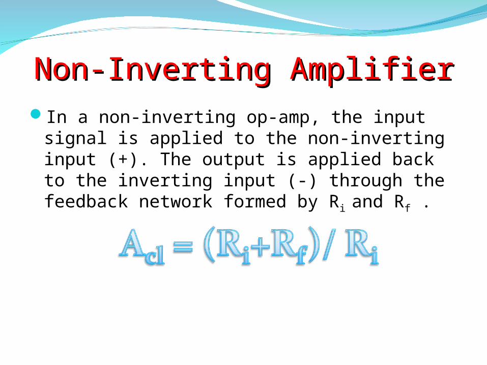
Non-Inverting AmplifierNon-Inverting AmplifierIn a non-inverting op-amp, the input signal is
applied to the non-inverting input (+). The output is applied back to the inverting input (-) through the feedback network formed by Ri and Rf .
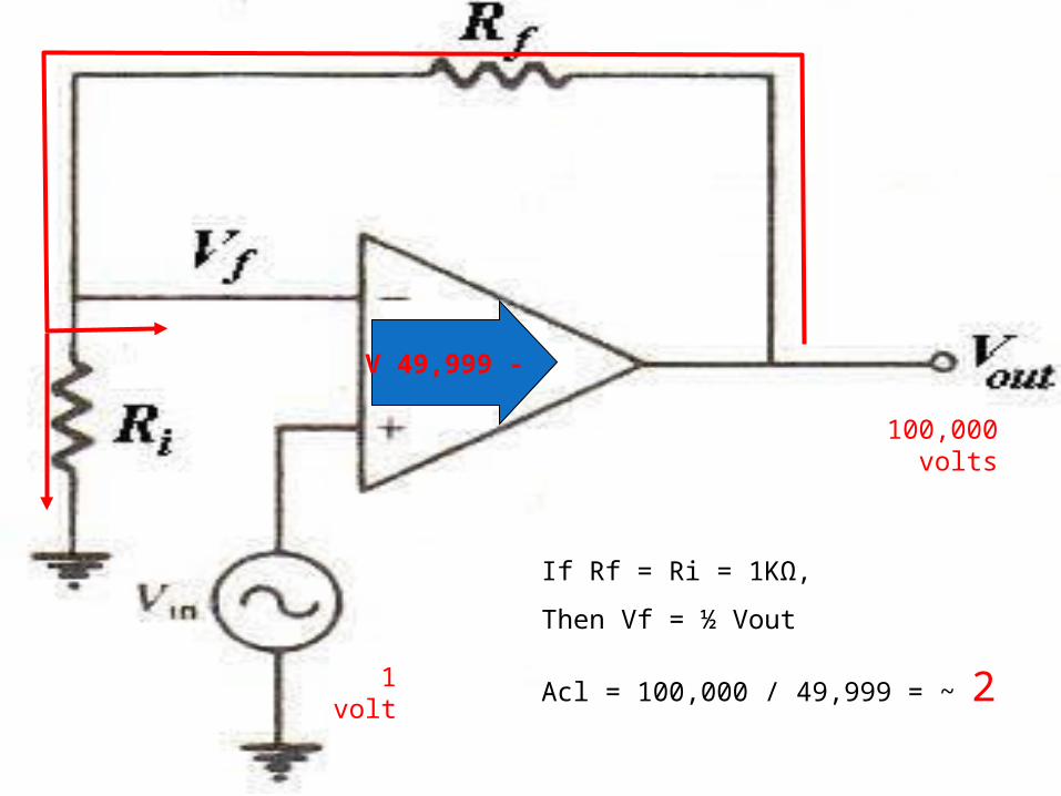
1 volt
100,000 volts
If Rf = Ri = 1KΩ,
Then Vf = ½ Vout
Acl = 100,000 / 49,999 = ~ 2
-49,999 V

Inverting AmplifierInverting AmplifierIn an inverting op-amp, the input signal is
applied through a series of input resistor Ri to the inverting input. Also, the output is feedback through Rf to the same input, The non-inverting input is grounded.

1 volt
100,000 volts
-50,001 V
If Rf = Ri = 1KΩ,
Then Vf = ½ Vout
Acl = 100,000 / 50,001 = ~ 2

ProcedureProcedure-:Non-inverting connection:Non-inverting connection:1. Connect the circuit of the non-inverting op-
amp. [ Ri (constant) = 1000 ; Rf (variable) = 0.5K, 1k, 2k, 3k, 5.5k, 8K and 10k)].
2. For each value of the Rf find the closed loop gain Acl experimentally (Vout/Vin), and theoretically ((Rf+Ri)/Ri).
3. Draw a relation between Acl and the values of Rf experimental and theoretical.


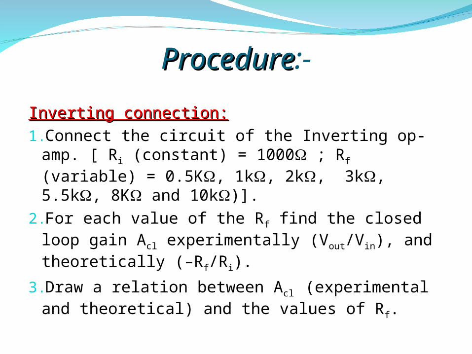
ProcedureProcedure:-
Inverting connection:Inverting connection:1.Connect the circuit of the Inverting op-amp. [
Ri (constant) = 1000 ; Rf (variable) = 0.5K, 1k, 2k, 3k, 5.5k, 8K and 10k)].
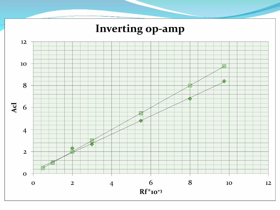
2.For each value of the Rf find the closed loop gain Acl experimentally (Vout/Vin), and theoretically (–Rf/Ri).
3.Draw a relation between Acl (experimental and theoretical) and the values of Rf.


ProcedureProcedure:-
1. Connect the circuit of the Inverting op-amp. [ Rin1 ,Rin2 are constant = 1000 ; Rf (variable) = 1k, 2k, 3k, 5.5k, and 8K ].
2. For each value of the Rf find the output voltage Vout experimentally, and theoretically (–Rf/R(Vin1+Vin2)).
3. Draw a relation between Vout (experimental and theoretical) and the values of Rf.


Thank youThank you
11/5/2008 26prepared by: Abdo A. Elfiky


