Int. J. Engg. Res. & Sci. & Tech. 2014 K S Arjun and P T .... J. Engg. Res.& Sci.& Tech. 2014 K S...
11
Transcript of Int. J. Engg. Res. & Sci. & Tech. 2014 K S Arjun and P T .... J. Engg. Res.& Sci.& Tech. 2014 K S...


This article can be downloaded from http://www.ijerst.com/currentissue.php
324
Int. J. Engg. Res. & Sci. & Tech. 2014 K S Arjun and P T Peter, 2014
ISSN 2319-5991 www.ijerst.com
Vol. 3, No. 2, May, 2014
© 2014 IJERST. All Rights Reserved
Research Paper
DESIGN OF HYDRAULIC SPRING LOADED RAILCLAMP OF SHIPUNLOADER
K S Arjun1* and P T Peter1
*Corresponding Author: K S Arjun, � [email protected]
The main problem of the presence of high velocity winds that will cause the unloader to movefrom its position and cause damages to the cargo and the machineryfor grab type ship unloaderis solved using a spring loaded hydraulic rail clamp mounted on a rail on which it can move tothe ship and unload materials steadily. Data collected from the FACT department about thewind characteristic of the area for a particular period were used and the wind loads acting onthe ship unloader is calculated. The maximum wind load that the ship unloader can withstandwhich has to be the one at which the spring loaded hydraulic clamp will disable is calculatedAfter carefully studying the already existing clamping system, we found that using an alternativespring concentrically, we can increase the wind load capacity which is the maximum load theclamp can withstand. After carefully analyzing different springs we found that with the use ofconcentric spring, the clamp can withstand a higher amount of wind load, thus increasing theperformance of ship unloader. This is proved by spring load calculations and using AutodeskInventor and ANSYS software.
Keywords: Design, Ship Unloader, Concentric Spring, Spring load, Shear stress, Total
deformation
INTRODUCTION
The grab type ship unloaders are capable of
unloading bulk materials with most different
attributes. All type of unloaders will have a long
travel drive for unloading from different points and
a rail clamp for holding it in place. The bottom
part of the unloader has four long travel drives
and two spring loaded hydraulic rail clamps. The
long travel drive is used to run the machine along
the rail and the rail clamp is used to clamp the
1 Department of Mechanical Engineering, Manav Bharti University, Solan, India.
machine in place against wind so that themachine does not move on its own.
In the hydraulic rail clamp spring, the use of
spring tension is used for clamping the truck on
to the rail to prevent the crane from a large wind
run. These rail clamps are storm brakes suitable
for small to medium forces from 50 to 500 K.W.
They are spring actuated i.e., the spring exercises
the closing force while a hydraulic cylinder fed
by suitable hydraulic unit provides the opening.
This article can be downloaded from http://www.ijerst.com/currentissue.php
325
Int. J. Engg. Res. & Sci. & Tech. 2014 K S Arjun and P T Peter, 2014
The value of forces indicated are calculated withfriction coefficient of 0.25 or 0.5. As the real co-efficient is much higher, (approx. 0.59 certifiedby TUV) the rail clamps have a good safety factor.
Chang (2010) did a case study on a grab shipunloader to evaluate its real strain responsesduring the static test and long-term monitoring.(Haddara and Soares, 1999) used a neuralnetwork technique to obtain an expression for theestimation of wind loads on ships and comparedwith the experimental data. (Lee and Low, 1993;Chen et al., 2010) obtained results of wind tunneltests on models of rigid offshore platforms,butwere very expensive. (Zimmer, 2003) pronouncedthat KBHseries is a hydraulically operated heavyload brake that presses directly onto the sectionrail guide via a piston mechanism. Thus the mainobjective of this work was to make a detailedstudy on the existing ship unloader and otherassociated machinery to suggest any possiblemodifications and to design a new system whichwill be more effective than the existing oneagainst the main problem of high velocity winds.
MATERIALS AND METHODS
A detailed overview of the Ship Unloader of FACTat Q10 Fertilizer Berth, Willingdon Island is takenso as to understand its working along with that ofHydraulic rail clamp. A graphical record of thedimensions of Ship Unloader under wind load ismade by measurement. The sketch is digitalizedusing the ANSYS software. Area of Ship Unloaderunder wind load is calculated.
The area calculated is then used to find theload on hydraulic rail clamp units due to windloading. The load on hydraulic rail clamp unit isfound out for different wind speeds which is thenused to calculate the diameter of spring inhydraulic rail clamp. The diameter so obtained isthe diameter required to withstand said wind load.This diameter is then compared to the diameter
of spring in use thus giving the maximum windspeed bearable by the current rail clamp system(Jalaluddin, 2004; Gupta and Khurmi, 2005).
Wind speeds of high velocity like 50m/s (180Kmph) are not uncommon in coastal regions. Asper the calculations done in this study, it is foundthat the maximum wind speed safely bearableby the Ship Unloader using conventional railclamp is 52m/s (187.2 Kmph) and it is unsafe ata speed of 53m/s (190.8 Kmph). As this is a shortmargin, it is advisable to improve the capacity ofthe rail clamp, if a technically viable andeconomically feasible method can be found. Forthis purpose, the modification of the conventionalsystem by using concentric spring is proposed.The maximum wind speed that can be safelyborne by the modified rail clamp using concentricsprings is calculated. Concentric springs improvethe capability of the Hydraulic rail clamp so thatit is able to withstand wind speeds of 58m/s (208.8Kmph) and it is unable to withstand a speed of59m/s (212.4 Kmph). This gives a very goodsafety margin.
Conventional formulae are used for the cal-culation of area of Ship Unloader, dynamic windpressure, wind load and normal reaction. TheWahl's stress factor is found out and is used tofind the diameter from the known value of shearstress. The calculation of spring index, numberof turns, free length and pitch of coil is done byconventional methods. Also physical propertiesof different materials are compared and the mostsuitable one is chosen for construction of spring.The total deformation and shear stress analysisof helical and concentric springs (Khanduri et al.,1997) are done for different wind speeds usingAutodesk Inventor and ANSYS.
RESULTS AND DISCUSSION
Design Details of Spring
Material: High Carbon Steel; spring coil diameter,
This article can be downloaded from http://www.ijerst.com/currentissue.php
326
Int. J. Engg. Res. & Sci. & Tech. 2014 K S Arjun and P T Peter, 2014
d=48mm; Outer diameter of spring, Do=300mm;Inner diameter of spring, Di=200mm; Freelength=630mm; Pitch, p=100mm; Number ofcoils=8 Design Details of Rail:Width = 100mm;Depth = 50mm; Distance between ends of thespring unit in rail clamp system (in expansion)=1200mm; Distance between ends of the springunit in rail clamp system (in compression) =1100mm; Total deflection of spring unit (consistingof 4 spring) = 1200-1100 = 100mm
Design Details of Hydraulic Jack
Hydraulic jack length = 750mm; Piston diameter= 90mm; Piston head=150mm
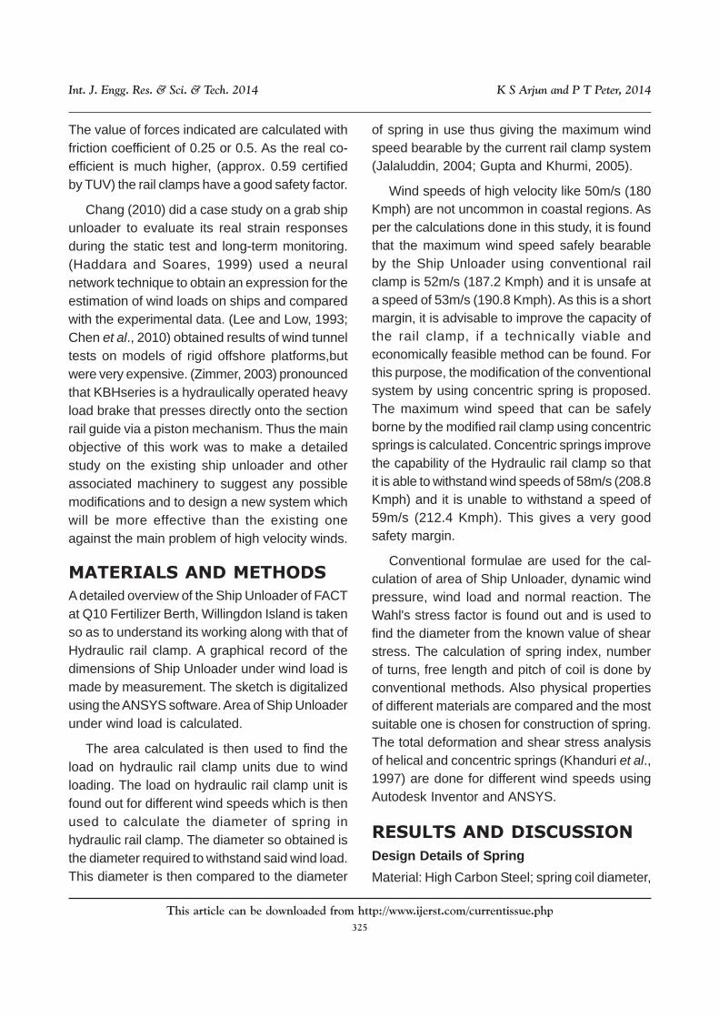
Effective Frontal Area of the Crane
From Figure 1; Area of legs + Area of lift + Areaof hopper + Area of machinery house + Area ofboom + Area of other beams = 104.343 + 45 +83.265 + 32.375 + 64 + 32.75 = 361.73 m2
load. Therefore the effective wind load on eachclamping unit = (F/2) = 305.66 KN
Consider one clamping unit. Clamping isprovided by means of pressure plates. Let µ =coefficient of static friction (depends on 2materials of contact) [µ = 1.6 (approximately)] F/2
= Wind load on each clamping unit; f = frictionalforce; N = normal reaction.
The normal reaction or compressive force(clamping force), N to be applied in order to holdthe unloader against sliding. Frictional force, f =µ× N; For machine to be in equilibrium, 2f = F/2
=> f = F/4 Required Clamping force, N = f/µ = F/4µ =95.52 K.
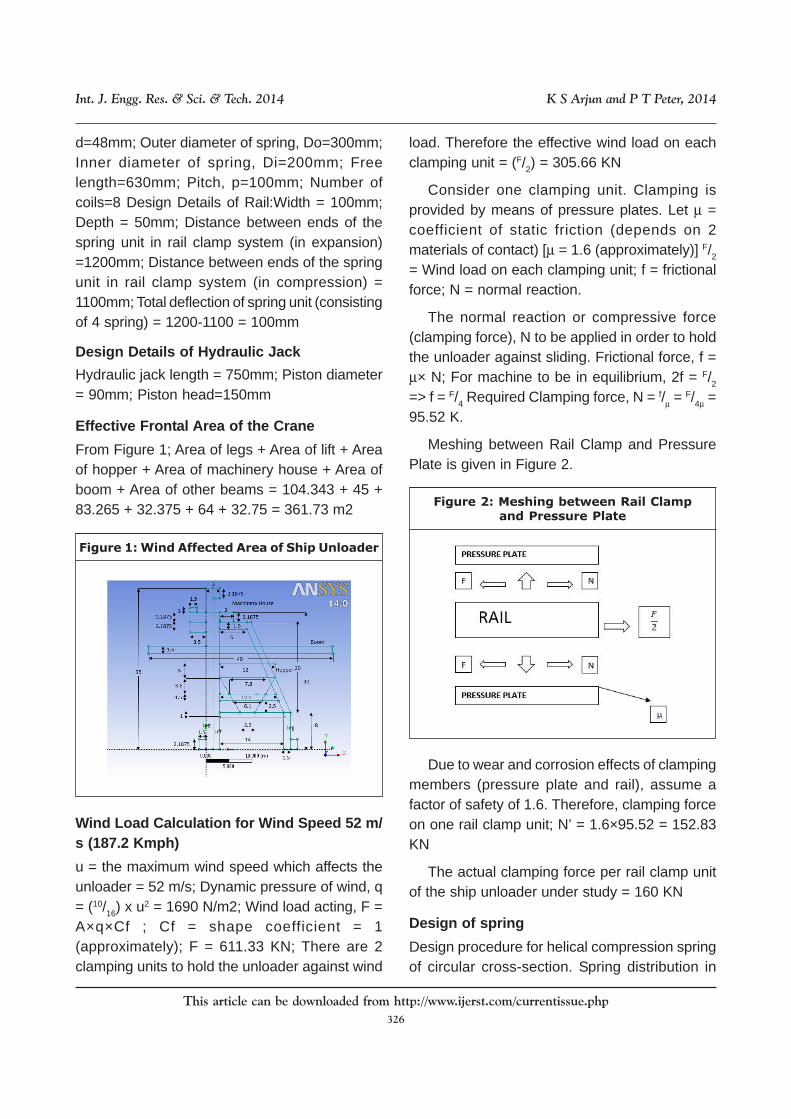
Meshing between Rail Clamp and PressurePlate is given in Figure 2.
Wind Load Calculation for Wind Speed 52 m/s (187.2 Kmph)
u = the maximum wind speed which affects theunloader = 52 m/s; Dynamic pressure of wind, q= (10/16) x u2 = 1690 N/m2; Wind load acting, F =A×q×Cf ; Cf = shape coefficient = 1(approximately); F = 611.33 KN; There are 2clamping units to hold the unloader against wind
Figure 2: Meshing between Rail Clampand Pressure Plate
Due to wear and corrosion effects of clampingmembers (pressure plate and rail), assume afactor of safety of 1.6. Therefore, clamping forceon one rail clamp unit; N’ = 1.6×95.52 = 152.83KN
The actual clamping force per rail clamp unitof the ship unloader under study = 160 KN
Design of spring
Design procedure for helical compression springof circular cross-section. Spring distribution in
Figure 1: Wind Affected Area of Ship Unloader

This article can be downloaded from http://www.ijerst.com/currentissue.php
327
Int. J. Engg. Res. & Sci. & Tech. 2014 K S Arjun and P T Peter, 2014
seriesand parallel (Figure3 and 4) to take up loadare estimated.
Figure 3: Helical Spring
Diameter of Wire
Shear stress τ Kx (8WC/πd2); Wahl’s stress factorKW = 4c-1 + 0.615 4c-1 c
Figure 4: Spring in Parallel and Series
Also refer for k value from DHB Figure; Springindex, C = D/d; Where d = diameter of spring wire;‘c’ generally varies from 4 to 12 for generaluse;From data hand book select standarddiameter for the spring wire.
Mean Diameter of Coil: Mean coil diameter, D= cd; Outer diameter of coil, Do = D+d; Innerdiameter of coil, Di = D-d; Number of coil or turns:n = δGd/8WC3; Where, n = Number of active turnsor coils; Free length: Lf = n’d + δ + (1.5 x δ)Combined stiffness of unit, K: 1/K = 1/2K + 1/2K = 2/2K
= 1/2K; K = K
Spring MaterialCarbon - 0.6 - 1.1%; Silicon - 0.2 - 0.5%; Manga-nese - 0.6 - 1%Load given of 4 spring for compression = clamp-ing force provided by the 4 springs in extension.Total clamping force on 1 clamping unit, N’ = KN;There are 4 springs distributed on each clamp-ing unit, load on each spring will be:
W = N = 152.83 = 38.21 KN 4 4
Modulus of rigidity of high carbon steel, G = 86KN/m2; Modulus of elasticity, E = 210 KN/mm2
Assumptions
Maximum allowable deflection of spring, ? =50mm; Maximum shear stress for wire, ? = 220MN/m2; Spring index, C = D/d = 4.
Spring diameter, d: According to Wahl’s stress
(4c-1)(4c-4)
K = ( +0.615
c( ((factor,
(Where spring index C=4, mathematically C= D/d,usually C should not be less than 4) K = 1.4 Maxi-mum shear stress Kx (8WC/ ); W = 38.21 KN;T= 220 MN/m2
220 x 106 = 1.4 x d2 =
0.002476630477; d = 0.04976575607; m = 49.77mm.
Mean diameter of spring coil, D = C x d = 199.06mm; Outer diameter of spring coil, D0 = D + d =248.83 mm; Number of turns of coil, n : Permis-sible compression of spring, 0 = 50mm (Fromgeometrical dimensions of clamping unit); Deflec-tion,
(8x38.21x1000x4)(πd
2)
δ = 8WC3n/G x d ; n = = 10.92; Number of
coils, n = 11; Total number of coils, n’ = n+2 = 13.
Free length of spring required, Lf = n’d + 0 +(0.15×0) = 703.05 mm Pitch of the coil, P: Pitch
(( δ Gd8WC3
This article can be downloaded from http://www.ijerst.com/currentissue.php
328
Int. J. Engg. Res. & Sci. & Tech. 2014 K S Arjun and P T Peter, 2014
of the coil = Lf (n - 1); p = 58.59mm.
The actual diameter is greater than calculateddiameter (Table 1), hence the spring can with-stand the wind speed 52m/s (187.2 Kmph).
Table 1: Comparison Between Actual andDesign Values for Wind Speed 52m/s
ACTUAL VALUE
Spring diameter, d = 50mm
Outer diameter, Do = 300mm
Mean diameter, D = 250mm
Total number of coils, n' = 8
Free length of spring, Lf = 630mm
Pitch of coil, P = 100mm
DESIGN VALUES
Spring diameter, d = 49.77mm
Outer diameter, Do = 248.83mm
Mean diameter, D = 196.06mm
Total number of coils, n' = 13
Free length of spring, Lf = 703.048m
Pitch of coil, P = 58.59mm
For Wind speed 53 m/s (190.8 Kmph)
The actual diameter is less than calculateddiameter (Table 2), hence the spring cannotwithstand the wind speed 53 m/s (190.8 Kmph).
Table 2: Comparison between Actual andDesign Values for Wind Speed 53m/s
ACTUAL VALUE
Spring diameter, d = 50mm
Outer diameter, Do = 300mm
Mean diameter, D = 250mm
Total number of coils, n' = 8
Free length of spring, Lf = 630mm
Pitch of coil, P = 100mm
DESIGN VALUES
Spring diameter, d = 50.72mm
Outer diameter, Do = 253.61mm
Mean diameter, D = 202.89mm
Total number of coils, n' = 13
Free length of spring, Lf = 716.90mm
Pitch of coil, P = 59.74mm
Design Modification by Concentric Spring
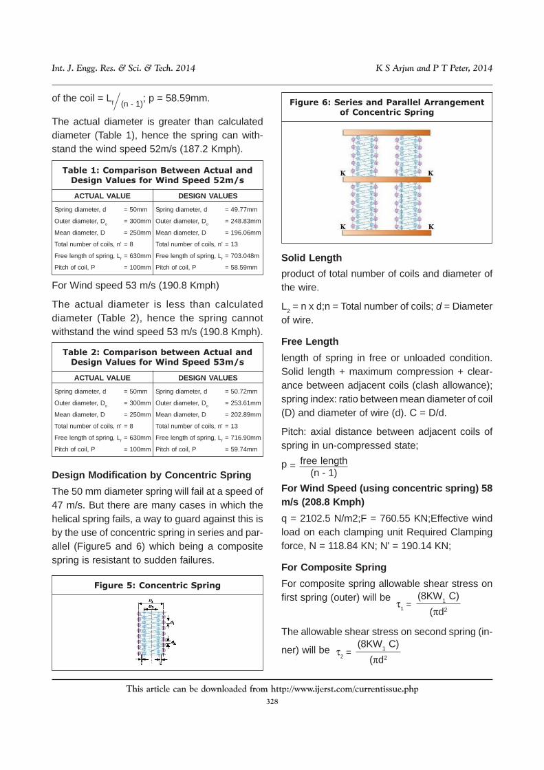
The 50 mm diameter spring will fail at a speed of47 m/s. But there are many cases in which thehelical spring fails, a way to guard against this isby the use of concentric spring in series and par-allel (Figure5 and 6) which being a compositespring is resistant to sudden failures.
Figure 5: Concentric Spring
Figure 6: Series and Parallel Arrangementof Concentric Spring
Solid Length
product of total number of coils and diameter ofthe wire.
L2 = n x d;n = Total number of coils; d = Diameterof wire.
Free Length
length of spring in free or unloaded condition.Solid length + maximum compression + clear-ance between adjacent coils (clash allowance);spring index: ratio between mean diameter of coil(D) and diameter of wire (d). C = D/d.
Pitch: axial distance between adjacent coils ofspring in un-compressed state;
p = free length(n - 1)
For Wind Speed (using concentric spring) 58m/s (208.8 Kmph)
q = 2102.5 N/m2;F = 760.55 KN;Effective windload on each clamping unit Required Clampingforce, N = 118.84 KN; N' = 190.14 KN;
For Composite Spring
For composite spring allowable shear stress onfirst spring (outer) will be
τ1 =
(8KW1 C)
(πd2
The allowable shear stress on second spring (in-
ner) will be τ2 =(8KW1 C)
(πd2

This article can be downloaded from http://www.ijerst.com/currentissue.php
329
Int. J. Engg. Res. & Sci. & Tech. 2014 K S Arjun and P T Peter, 2014
W1, W2 = Load shared by outer and innerspring respectively; d1, d2 = Wire diameter of outerand inner spring respectively; D1, D2 = Mean di-ameter of outer and inner spring respectively.
For a concentric spring the induced stress, de-flection, free length and solid length of both thesprings are same. Also, the diametral clearancebetween the springs is assumed to be equal tothe difference between wire diameters.
Now for above conditions we have,
D1 – D2 = 2d1; D1 = Cd1 and D2 = Cd2 (...2)
W2
W1 =d2
d1( (2
As C = 4;
d2
d1 =(C – 2)
C
d2
d1 =(4 – 2)
4= 2; Substituting
above value in equation 1
W2
W1 = 22 = 4
As, W1 + W2 = W = 47.53 KN (...5) Solvingequations 4 and 5 we get W1 = 38.03 KN; W2 =9.51 KN
Since τ1 = τ2 we have τ1
(...3)
(...4)
(πd2) 1
(8KW1C)
= 220 N / mm2 (...6)
(πd2) 2
τ2 (8KW2C)(...7)= 220 N / mm2
Applying values for equations 6 and 7; d1 =49.65mm and. d2 = 24.82 mm.
Applying values of d1 and d2 in equation 2; D1 =198.59mm and D2 = 99.30mm
Since the deflection produced by both the springsare equal (i.e. δ1 = δ2) and δ = 50
n1 = (δGd1) = 10.20 = 11n2(8W1C3)
(δGd2)(8W2C
3)
= 20.40 = 21
Both springs are made with squared and groundends.N1 = n1 + 2 = 13; N2 = n2 + 2 = 23Free length of outer spring (Lf1) free length of in-nerSpring (Lf2) = Ls1 + 1.15δmax = N1d1 + 1.15δmax =
702.92 mm; Pitch of outer spring,
P1 = = 58.58 mm
Pitch of inner spring, P2 = 31.95mm
Outer diameter of outer spring, D01 = D1 + d1 =248.24 mm
Outer diameter of inner spring, D02 = D2 + d2 =124.12 mm
Inner diameter of outer spring, Df1 = D1 + d1 =148.94 mm
Inner diameter of outer spring, Df1 = D2 + d2 =74.47 mm
Composite spring (Concentric spring) is able towithstand (Table 3) wind speed of 58m/s.
(Lf1) (N1 – 1)(Lf2) (N2 – 1)
Sl.Description Outer Spring Inner SpringNo.
1 Wire diameter 49.5mm 24.82mm
2 Mean diameter of spring 198.59mm 99.30mm
3 Outer diameter of spring 248.24mm 124.12mm
4 Inner diameter of spring 148.94mm 74.47mm
5 Number of Coils 13 23
6 Free length 702.92mm 702.92mm
7 Pitch of spring 58.58mm 31.95mm
Table 3: Design Values of ConcentricSpring for 58m/s
Wind speed (using concentric spring) 59 m/s(212.4 Kmph)
Spring Type: Concentric. Composite spring is notable to withstand (Table 4) wind speed of 59m/s(212.4 Kmph)
This article can be downloaded from http://www.ijerst.com/currentissue.php
330
Int. J. Engg. Res. & Sci. & Tech. 2014 K S Arjun and P T Peter, 2014
Sl.Description Outer Spring Inner SpringNo.
1 Wire diameter 50.50mm 25.25mm
2 Mean diameter of spring 202.02mm 101.01mm
3 Outer diameter of spring 252.52mm 126.26mm
4 Inner diameter of spring 151.51mm 75.76mm
5 Number of Coils 13 23
6 Free length 669.5mm 669.5mm
7 Pitch of spring 60.86mm 31.88mm
Table 4: Design Values of ConcentricSpring for 59m/s
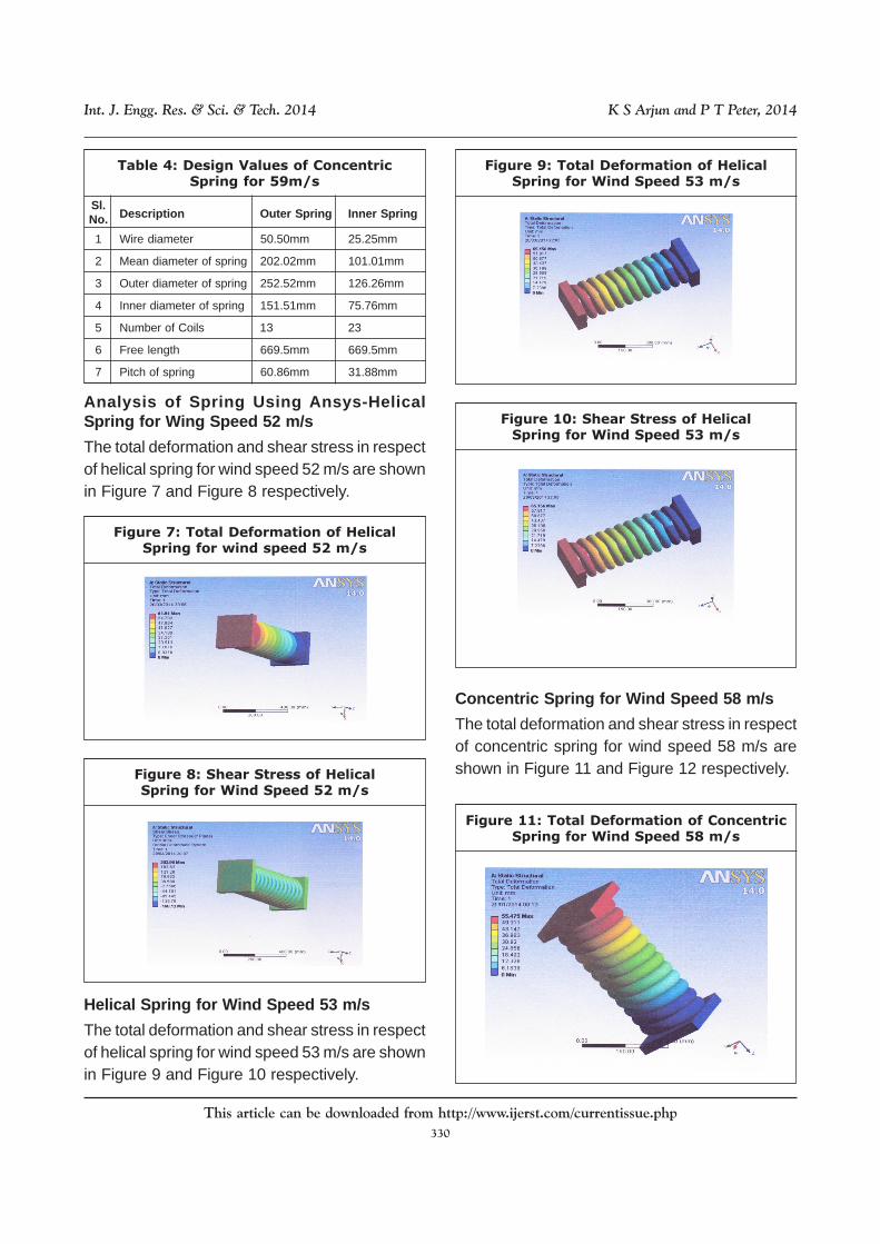
Analysis of Spring Using Ansys-HelicalSpring for Wing Speed 52 m/s
The total deformation and shear stress in respectof helical spring for wind speed 52 m/s are shownin Figure 7 and Figure 8 respectively.
Figure 7: Total Deformation of HelicalSpring for wind speed 52 m/s
Figure 8: Shear Stress of HelicalSpring for Wind Speed 52 m/s
Concentric Spring for Wind Speed 58 m/s
The total deformation and shear stress in respectof concentric spring for wind speed 58 m/s areshown in Figure 11 and Figure 12 respectively.
Figure 9: Total Deformation of HelicalSpring for Wind Speed 53 m/s
Figure 10: Shear Stress of HelicalSpring for Wind Speed 53 m/s
Figure 11: Total Deformation of ConcentricSpring for Wind Speed 58 m/s
Helical Spring for Wind Speed 53 m/s
The total deformation and shear stress in respectof helical spring for wind speed 53 m/s are shownin Figure 9 and Figure 10 respectively.
This article can be downloaded from http://www.ijerst.com/currentissue.php
331
Int. J. Engg. Res. & Sci. & Tech. 2014 K S Arjun and P T Peter, 2014
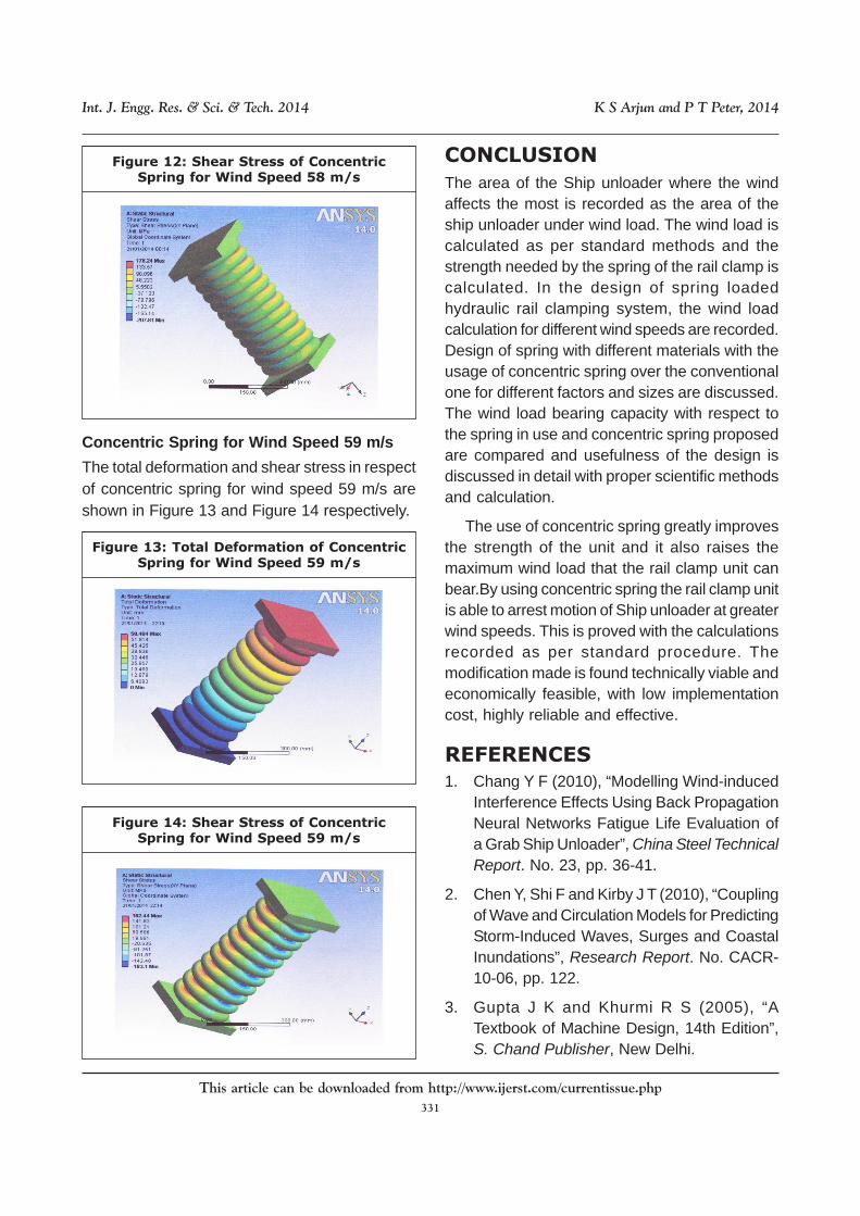
Concentric Spring for Wind Speed 59 m/s
The total deformation and shear stress in respectof concentric spring for wind speed 59 m/s areshown in Figure 13 and Figure 14 respectively.
Figure 12: Shear Stress of ConcentricSpring for Wind Speed 58 m/s
Figure 13: Total Deformation of ConcentricSpring for Wind Speed 59 m/s
Figure 14: Shear Stress of ConcentricSpring for Wind Speed 59 m/s
CONCLUSION
The area of the Ship unloader where the windaffects the most is recorded as the area of theship unloader under wind load. The wind load iscalculated as per standard methods and thestrength needed by the spring of the rail clamp iscalculated. In the design of spring loadedhydraulic rail clamping system, the wind loadcalculation for different wind speeds are recorded.Design of spring with different materials with theusage of concentric spring over the conventionalone for different factors and sizes are discussed.The wind load bearing capacity with respect tothe spring in use and concentric spring proposedare compared and usefulness of the design isdiscussed in detail with proper scientific methodsand calculation.
The use of concentric spring greatly improvesthe strength of the unit and it also raises themaximum wind load that the rail clamp unit canbear.By using concentric spring the rail clamp unitis able to arrest motion of Ship unloader at greaterwind speeds. This is proved with the calculationsrecorded as per standard procedure. Themodification made is found technically viable andeconomically feasible, with low implementationcost, highly reliable and effective.
REFERENCES
1. Chang Y F (2010), “Modelling Wind-inducedInterference Effects Using Back PropagationNeural Networks Fatigue Life Evaluation ofa Grab Ship Unloader”, China Steel TechnicalReport. No. 23, pp. 36-41.
2. Chen Y, Shi F and Kirby J T (2010), “Couplingof Wave and Circulation Models for PredictingStorm-Induced Waves, Surges and CoastalInundations”, Research Report. No. CACR-10-06, pp. 122.
3. Gupta J K and Khurmi R S (2005), “ATextbook of Machine Design, 14th Edition”,S. Chand Publisher, New Delhi.
This article can be downloaded from http://www.ijerst.com/currentissue.php
332
Int. J. Engg. Res. & Sci. & Tech. 2014 K S Arjun and P T Peter, 2014
4. Haddara M R and Soares G C (1999), “WindLoads on Marine Structures”, MarineStructures. Vol. 12, No. 3, pp. 199-209.
5. Jalaluddin S M (2004), “Design Data HandBook, Anuradha Agencies Publications,Karuppur.
6. Khanduri A C, Bédard C and Stathopoulos T(1997), “Modelling Wind-inducedInterference Effects Using Back PropagationNeural Networks”, Journal of Wind
Engineering and Industrial Aerodynamics.Vol. 72, pp. 71-79.
7. Lee T S and Low H T (1993), “Wind Effectson Offshore Platforms: A Wind Tunnel ModelStudy”, Proceedings of the Third InternationalOffshore and Polar Engineering Conference.Singapore, pp. 466-470.
8. Zimmer G M B H (2003), “Hydraulic HeavyLoad Brake: The Braking and ClampingElement With Membrane Technology KBH”,www.zimmer-gmbh.com pp. 95.